the computer-aided design and rapid prototyping ... · loughborough university institutional...
TRANSCRIPT
Loughborough UniversityInstitutional Repository
The computer-aided designand rapid prototyping
fabrication of removablepartial denture frameworks
This item was submitted to Loughborough University's Institutional Repositoryby the/an author.
Citation: EGGBEER, D., BIBB, R.J. and WILLIAMS, R.J., 2005. Thecomputer-aided design and rapid prototyping fabrication of removable partialdenture frameworks. Proceedings of the Institution of Mechanical Engineers,Part H: Journal of Engineering in Medicine, 219 (3), pp. 195-202
Additional Information:
• This is an article from the journal, Proceedings of the IMechE, Part H:Journal of Engineering in Medicine [ c© IMechE ]. It is also available at:http://dx.doi.org/10.1243/095441105X9372
Metadata Record: https://dspace.lboro.ac.uk/2134/5708
Version: Published
Publisher: Professional Engineering Publishing / c© IMechE
Please cite the published version.
This item was submitted to Loughborough’s Institutional Repository (https://dspace.lboro.ac.uk/) by the author and is made available under the
following Creative Commons Licence conditions.
For the full text of this licence, please go to: http://creativecommons.org/licenses/by-nc-nd/2.5/
195
The computer-aided design and rapid prototypingfabrication of removable partial denture frameworksD Eggbeer1*, R Bibb1, and R Williams2
1 The National Centre for Product Design and Development Research, The University of Wales Institute, Cardiff, UK2 Centre for Dental Technology, University of Wales Institute, Cardiff, UK
The manuscript was received on 12 August 2004 and was accepted after revision for publication on 13 January 2005.
DOI: 10.1243/095441105X9372
Abstract: This study explores the application of computer-aided design and manufacture (CAD/CAM) to the process of electronically surveying a scanned dental cast as a prior stage to producing asacrificial pattern for a removable partial denture (RPD) metal alloy framework. These are designedto retain artificial replacement teeth in the oral cavity. A cast produced from an impression of apatient’s mouth was digitally scanned and the data converted to a three-dimensional computer filethat could be read by the computer-aided design (CAD) software. Analysis and preparation werecarried out in the digital environment according to established dental principles. The CAD softwarewas then used to design the framework and generate a standard triangulation language (STL) file inpreparation for its manufacture using rapid prototyping (RP) methods. Several RP methods weresubsequently used to produce sacrificial patterns, which were then cast in a chromium–cobalt alloyusing conventional methods and assessed for accuracy of fit.
This work demonstrates that CAD/CAM techniques can be used for electronic dental cast analysis,preparation, and design of RPD frameworks. It also demonstrates that RP-produced patterns maybe successfully cast using conventional methods and that the resulting frameworks can provide asatisfactory fit.
Keywords: computer-aided design, rapid prototyping, removable partial denture
1 INTRODUCTION of metal alloy components of RPD metal frameworkscould have promising applications [7, 8]. Thesestudies explored the application of computer-aidedComputer-aided design and manufacture (CAD/
CAM) and rapid prototyping (RP) techniques have technologies to the surveying of digital casts andpattern design and the subsequent production ofbeen extensively employed in the product develop-
ment sector for many years and have also been sacrificial patterns using RP technologies.The potential advantages offered by the introduc-extensively used in maxillofacial technology and
surgery [1–3]. In addition, CAD/CAM technologies tion of advanced CAD/CAM and RP into the field ofRPD framework fabrication include automatic deter-have been introduced into dentistry, particularly for
the manufacture of crowns and bridges [4–6], but mination of a suggested path of insertion, the almostinstant elimination of unwanted undercuts (re-entrythere has been little research into the use of such
methods in the field of removable partial denture points), and the equally rapid identification of use-ful undercuts. At another stage, components of an(RPD) framework fabrication. This may in part be
attributed to the lack of suitable dedicated software. RPD could be stored in a library and ‘dragged anddropped’ in place on a scanned and digitally sur-Recent pilot studies have showed that computer-
aided design (CAD) and RP methods of designing veyed cast from icons appearing on screen, allowingvirtual pattern making to be carried out in a muchand producing a sacrificial pattern for the productionfaster time than is achieved by current techniques.
* Corresponding author: The National Centre for Product Design The quality assurance of component design can alsobe built into the software. Since RP machines buildand Developmental Research, The University of Wales Institute,
Cardiff, Western Avenue, Cardiff CF5 2YB, UK. email: deggbeer-pdr@ the object directly, scaling factors may also be pre-cisely imposed in order to compensate for shrinkageuwic.ac.uk
H05404 © IMechE 2005 Proc. IMechE. Vol. 219 Part H: J. Engineering in Medicine
196 D Eggbeer, R Bibb, and R Williams
in casting. In addition to the potential time savings,the CAD/RP process also delivers inherent repeat-ability, which may help to eliminate operator vari-ation and to improve quality control in the dentallaboratory.
The current paper reports an investigation into theapplication of CAD and RP methods to achieve thestages of surveying and design using an appropriateCAD software package. It also discusses the appli-cation of RP technologies to produce sacrificialpatterns for casting the definitive chromium–cobaltframework component. The advantages, limitations,and future possibilities of these techniques areconcluded.
2 MATERIALS AND METHODS
2.1 Three-dimensional scanning
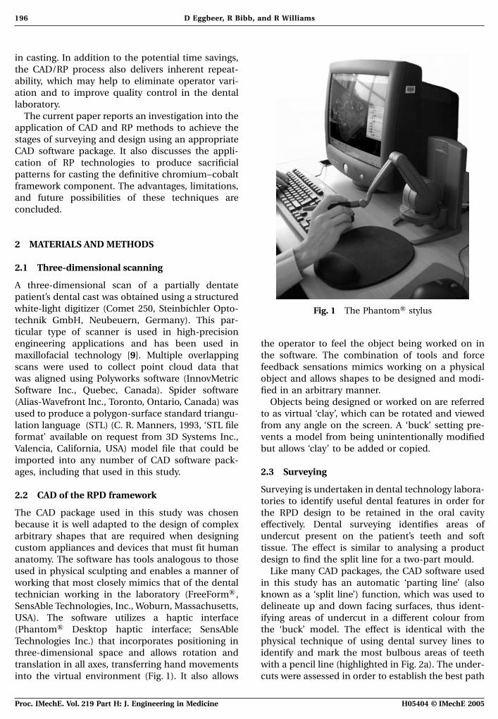
A three-dimensional scan of a partially dentatepatient’s dental cast was obtained using a structuredwhite-light digitizer (Comet 250, Steinbichler Opto- Fig. 1 The PhantomA stylustechnik GmbH, Neubeuern, Germany). This par-ticular type of scanner is used in high-precisionengineering applications and has been used in the operator to feel the object being worked on in
the software. The combination of tools and forcemaxillofacial technology [9]. Multiple overlappingscans were used to collect point cloud data that feedback sensations mimics working on a physical
object and allows shapes to be designed and modi-was aligned using Polyworks software (InnovMetricSoftware Inc., Quebec, Canada). Spider software fied in an arbitrary manner.
Objects being designed or worked on are referred(Alias-Wavefront Inc., Toronto, Ontario, Canada) wasused to produce a polygon-surface standard triangu- to as virtual ‘clay’, which can be rotated and viewed
from any angle on the screen. A ‘buck’ setting pre-lation language (STL) (C. R. Manners, 1993, ‘STL fileformat’ available on request from 3D Systems Inc., vents a model from being unintentionally modified
but allows ‘clay’ to be added or copied.Valencia, California, USA) model file that could beimported into any number of CAD software pack-ages, including that used in this study. 2.3 Surveying
Surveying is undertaken in dental technology labora-2.2 CAD of the RPD framework
tories to identify useful dental features in order forthe RPD design to be retained in the oral cavityThe CAD package used in this study was chosen
because it is well adapted to the design of complex effectively. Dental surveying identifies areas ofundercut present on the patient’s teeth and softarbitrary shapes that are required when designing
custom appliances and devices that must fit human tissue. The effect is similar to analysing a productdesign to find the split line for a two-part mould.anatomy. The software has tools analogous to those
used in physical sculpting and enables a manner of Like many CAD packages, the CAD software usedin this study has an automatic ‘parting line’ (alsoworking that most closely mimics that of the dental
technician working in the laboratory (FreeFormA , known as a ‘split line’) function, which was used todelineate up and down facing surfaces, thus ident-SensAble Technologies, Inc., Woburn, Massachusetts,
USA). The software utilizes a haptic interface ifying areas of undercut in a different colour fromthe ‘buck’ model. The effect is identical with the(PhantomA Desktop haptic interface; SensAble
Technologies Inc.) that incorporates positioning in physical technique of using dental survey lines toidentify and mark the most bulbous areas of teeththree-dimensional space and allows rotation and
translation in all axes, transferring hand movements with a pencil line (highlighted in Fig. 2a). The under-cuts were assessed in order to establish the best pathinto the virtual environment (Fig. 1). It also allows
H05404 © IMechE 2005Proc. IMechE. Vol. 219 Part H: J. Engineering in Medicine
197CAD and rapid prototyping fabrication of removable partial denture frameworks
(a) (b)
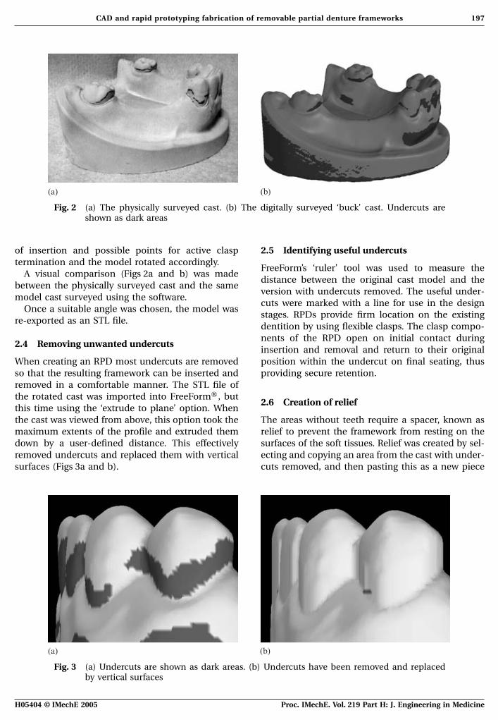
Fig. 2 (a) The physically surveyed cast. (b) The digitally surveyed ‘buck’ cast. Undercuts areshown as dark areas
of insertion and possible points for active clasp 2.5 Identifying useful undercutstermination and the model rotated accordingly.
FreeForm’s ‘ruler’ tool was used to measure theA visual comparison (Figs 2a and b) was made
distance between the original cast model and thebetween the physically surveyed cast and the same
version with undercuts removed. The useful under-model cast surveyed using the software.
cuts were marked with a line for use in the designOnce a suitable angle was chosen, the model was
stages. RPDs provide firm location on the existingre-exported as an STL file.
dentition by using flexible clasps. The clasp compo-nents of the RPD open on initial contact during
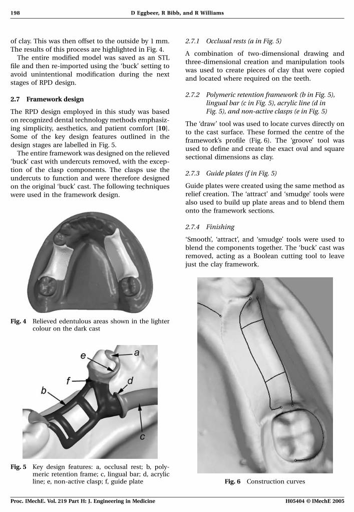
2.4 Removing unwanted undercutsinsertion and removal and return to their originalposition within the undercut on final seating, thusWhen creating an RPD most undercuts are removed
so that the resulting framework can be inserted and providing secure retention.removed in a comfortable manner. The STL file ofthe rotated cast was imported into FreeFormA , but
2.6 Creation of reliefthis time using the ‘extrude to plane’ option. Whenthe cast was viewed from above, this option took the The areas without teeth require a spacer, known as
relief to prevent the framework from resting on themaximum extents of the profile and extruded themdown by a user-defined distance. This effectively surfaces of the soft tissues. Relief was created by sel-
ecting and copying an area from the cast with under-removed undercuts and replaced them with verticalsurfaces (Figs 3a and b). cuts removed, and then pasting this as a new piece
(a) (b)
Fig. 3 (a) Undercuts are shown as dark areas. (b) Undercuts have been removed and replacedby vertical surfaces
H05404 © IMechE 2005 Proc. IMechE. Vol. 219 Part H: J. Engineering in Medicine
198 D Eggbeer, R Bibb, and R Williams
of clay. This was then offset to the outside by 1 mm. 2.7.1 Occlusal rests (a in Fig. 5)The results of this process are highlighted in Fig. 4.
A combination of two-dimensional drawing andThe entire modified model was saved as an STL
three-dimensional creation and manipulation toolsfile and then re-imported using the ‘buck’ setting to
was used to create pieces of clay that were copiedavoid unintentional modification during the next
and located where required on the teeth.stages of RPD design.
2.7.2 Polymeric retention framework (b in Fig. 5),2.7 Framework design lingual bar (c in Fig. 5), acrylic line (d in
Fig. 5), and non-active clasps (e in Fig. 5)The RPD design employed in this study was basedon recognized dental technology methods emphasiz- The ‘draw’ tool was used to locate curves directly oning simplicity, aesthetics, and patient comfort [10]. to the cast surface. These formed the centre of theSome of the key design features outlined in the framework’s profile (Fig. 6). The ‘groove’ tool wasdesign stages are labelled in Fig. 5. used to define and create the exact oval and square
The entire framework was designed on the relieved sectional dimensions as clay.‘buck’ cast with undercuts removed, with the excep-tion of the clasp components. The clasps use the 2.7.3 Guide plates (f in Fig. 5)undercuts to function and were therefore designed
Guide plates were created using the same method ason the original ‘buck’ cast. The following techniquesrelief creation. The ‘attract’ and ‘smudge’ tools werewere used in the framework design.also used to build up plate areas and to blend themonto the framework sections.
2.7.4 Finishing
‘Smooth’, ‘attract’, and ‘smudge’ tools were used toblend the components together. The ‘buck’ cast wasremoved, acting as a Boolean cutting tool to leavejust the clay framework.
Fig. 4 Relieved edentulous areas shown in the lightercolour on the dark cast
Fig. 5 Key design features: a, occlusal rest; b, poly-meric retention frame; c, lingual bar; d, acrylic
Fig. 6 Construction curvesline; e, non-active clasp; f, guide plate
H05404 © IMechE 2005Proc. IMechE. Vol. 219 Part H: J. Engineering in Medicine
199CAD and rapid prototyping fabrication of removable partial denture frameworks
2.7.5 Active clasps port structure (Fig. 8). The framework was orientedwith the fitting surfaces facing upwards to avoid the
The clasps were designed in the same manner as therough finish created by the support structures affect-
non-flexible parts of the framework, but using theing fit.
‘buck’ cast with undercuts. The construction linesTwo build styles were compared: standard layers
were joined to the termination point previously0.1000 mm thick and high-resolution layers
marked in the undercut measurement stage.0.0625 mm thick. Once completed, the patterns were
The ‘buck’ cast was removed leaving the clasps.carefully removed from the machine platform and
These were joined to the main framework andcleaned in isopropanol. They were then post cured
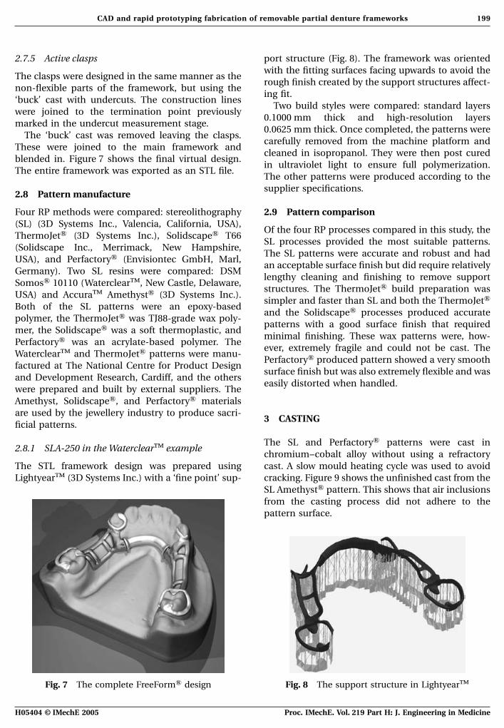
blended in. Figure 7 shows the final virtual design.in ultraviolet light to ensure full polymerization.
The entire framework was exported as an STL file.The other patterns were produced according to thesupplier specifications.
2.8 Pattern manufacture
Four RP methods were compared: stereolithography 2.9 Pattern comparison(SL) (3D Systems Inc., Valencia, California, USA),
Of the four RP processes compared in this study, theThermoJetA (3D Systems Inc.), SolidscapeA T66
SL processes provided the most suitable patterns.(Solidscape Inc., Merrimack, New Hampshire,
The SL patterns were accurate and robust and hadUSA), and PerfactoryA (Envisiontec GmbH, Marl,
an acceptable surface finish but did require relativelyGermany). Two SL resins were compared: DSM
lengthy cleaning and finishing to remove supportSomosA 10110 (WaterclearTM, New Castle, Delaware,
structures. The ThermoJetA build preparation wasUSA) and AccuraTM AmethystA (3D Systems Inc.).
simpler and faster than SL and both the ThermoJetABoth of the SL patterns were an epoxy-based
and the SolidscapeA processes produced accuratepolymer, the ThermoJetA was TJ88-grade wax poly-
patterns with a good surface finish that requiredmer, the SolidscapeA was a soft thermoplastic, and
minimal finishing. These wax patterns were, how-PerfactoryA was an acrylate-based polymer. The
ever, extremely fragile and could not be cast. TheWaterclearTM and ThermoJetA patterns were manu-
PerfactoryA produced pattern showed a very smoothfactured at The National Centre for Product Design
surface finish but was also extremely flexible and wasand Development Research, Cardiff, and the others
easily distorted when handled.were prepared and built by external suppliers. TheAmethyst, SolidscapeA, and PerfactoryA materialsare used by the jewellery industry to produce sacri-
3 CASTINGficial patterns.
The SL and PerfactoryA patterns were cast in2.8.1 SLA-250 in the WaterclearTM example
chromium–cobalt alloy without using a refractorycast. A slow mould heating cycle was used to avoidThe STL framework design was prepared using
LightyearTM (3D Systems Inc.) with a ‘fine point’ sup- cracking. Figure 9 shows the unfinished cast from theSL AmethystA pattern. This shows that air inclusionsfrom the casting process did not adhere to thepattern surface.
Fig. 7 The complete FreeFormA design Fig. 8 The support structure in LightyearTM
H05404 © IMechE 2005 Proc. IMechE. Vol. 219 Part H: J. Engineering in Medicine
200 D Eggbeer, R Bibb, and R Williams
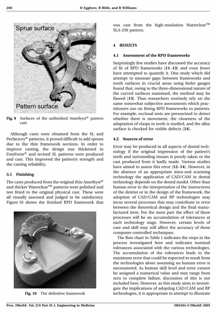
was cast from the high-resolution WaterclearTM
SLA-250 pattern.
4 RESULTS
4.1 Assessment of the RPD frameworks
Surprisingly few studies have discussed the accuracyof fit of RPD frameworks [11–13] and even fewerhave attempted to quantify it. One study which didattempt to measure gaps between frameworks andtooth surfaces in crucial areas using feeler gaugesfound that, owing to the three-dimensional nature ofthe curved surfaces examined, the method may beflawed [13]. Thus researchers routinely rely on thesame somewhat subjective assessments which prac-titioners use on fitting RPD frameworks to patients.For example, occlusal rests are pressurized to detect
Fig. 9 Surfaces of the unfinished AmethystA pattern whether there is movement, the closeness of thecast adaptation of clasps to teeth is studied, and the alloy
surface is checked for visible defects [14].Although casts were obtained from the SL and
4.2 Sources of errorPerfactoryA patterns, it proved difficult to add spruesdue to the thin framework sections. In order to
Error may be produced in all aspects of dental tech-improve casting, the design was thickened in
nology if the original impression of the patient’sFreeFormA and revised SL patterns were produced
teeth and surrounding tissues is poorly taken or theand cast. This improved the pattern’s strength and
cast produced from it badly made. Various studiesthe casting reliability.
have aimed to assess this error [12–14]. However, inthe absence of an appropriate intra-oral scanning
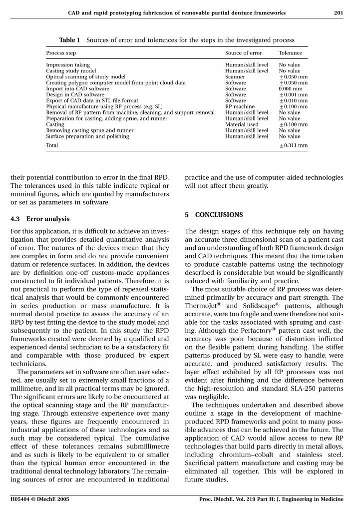
3.1 Finishingtechnology the application of CAD/CAM in dentaltechnology depends on the dental model. Other thanThe casts produced from the original thin AmethystAhuman error in the interpretation of the instructionsand thicker WaterclearTM patterns were polished andof the dentist or in the design of the framework, thetest fitted to the original physical cast. These wereadoption of CAD/CAM and RP technologies mayall visually assessed and judged to be satisfactory.incur several processes that may contribute to errorFigure 10 shows the finished RPD framework thatbetween the theoretical design and the final manu-factured item. For the most part the effect of theseprocesses will be an accumulation of tolerances ateach technology stage. However, certain levels ofcare and skill may still affect the accuracy of thesecomputer-controlled techniques.
The flow chart in Table 1 indicates the steps in theprocess investigated here and indicates nominaltolerances associated with the various technologies.The accumulation of the tolerances leads to themaximum error that could be expected to result fromthe technologies alone assuming no human error isencountered. As human skill level and error cannotbe assigned a numerical value and may range fromzero to complete failure, discussion of this is notincluded here. However, as this study aims to investi-gate the implications of adopting CAD/CAM and RP
Fig. 10 The definitive framework technologies, it is appropriate to attempt to illustrate
H05404 © IMechE 2005Proc. IMechE. Vol. 219 Part H: J. Engineering in Medicine
201CAD and rapid prototyping fabrication of removable partial denture frameworks
Table 1 Sources of error and tolerances for the steps in the investigated process
Process step Source of error Tolerance
Impression taking Human/skill level No valueCasting study model Human/skill level No valueOptical scanning of study model Scanner ±0.050 mmCreating polygon computer model from point cloud data Software ±0.050 mmImport into CAD software Software 0.000 mmDesign in CAD software Software ±0.001 mmExport of CAD data in STL file format Software ±0.010 mmPhysical manufacture using RP process (e.g. SL) RP machine ±0.100 mmRemoval of RP pattern from machine, cleaning, and support removal Human/skill level No valuePreparation for casting, adding sprue, and runner Human/skill level No valueCasting Material used ±0.100 mmRemoving casting sprue and runner Human/skill level No valueSurface preparation and polishing Human/skill level No value
Total ±0.311 mm
their potential contribution to error in the final RPD. practice and the use of computer-aided technologieswill not affect them greatly.The tolerances used in this table indicate typical or
nominal figures, which are quoted by manufacturersor set as parameters in software.
5 CONCLUSIONS4.3 Error analysis
For this application, it is difficult to achieve an inves- The design stages of this technique rely on havingan accurate three-dimensional scan of a patient casttigation that provides detailed quantitative analysis
of error. The natures of the devices mean that they and an understanding of both RPD framework designand CAD techniques. This meant that the time takenare complex in form and do not provide convenient
datum or reference surfaces. In addition, the devices to produce castable patterns using the technologydescribed is considerable but would be significantlyare by definition one-off custom-made appliances
constructed to fit individual patients. Therefore, it is reduced with familiarity and practice.The most suitable choice of RP process was deter-not practical to perform the type of repeated statis-
tical analysis that would be commonly encountered mined primarily by accuracy and part strength. TheThermoJetA and SolidscapeA patterns, althoughin series production or mass manufacture. It is
normal dental practice to assess the accuracy of an accurate, were too fragile and were therefore not suit-able for the tasks associated with spruing and cast-RPD by test fitting the device to the study model and
subsequently to the patient. In this study the RPD ing. Although the PerfactoryA pattern cast well, theaccuracy was poor because of distortion inflictedframeworks created were deemed by a qualified and
experienced dental technician to be a satisfactory fit on the flexible pattern during handling. The stifferpatterns produced by SL were easy to handle, wereand comparable with those produced by expert
technicians. accurate, and produced satisfactory results. Thelayer effect exhibited by all RP processes was notThe parameters set in software are often user selec-
ted, are usually set to extremely small fractions of a evident after finishing and the difference betweenthe high-resolution and standard SLA-250 patternsmillimetre, and in all practical terms may be ignored.
The significant errors are likely to be encountered at was negligible.The techniques undertaken and described abovethe optical scanning stage and the RP manufactur-
ing stage. Through extensive experience over many outline a stage in the development of machine-produced RPD frameworks and point to many poss-years, these figures are frequently encountered in
industrial applications of these technologies and as ible advances that can be achieved in the future. Theapplication of CAD would allow access to new RPsuch may be considered typical. The cumulative
effect of these tolerances remains submillimetre technologies that build parts directly in metal alloys,including chromium–cobalt and stainless steel.and as such is likely to be equivalent to or smaller
than the typical human error encountered in the Sacrificial pattern manufacture and casting may beeliminated all together. This will be explored intraditional dental technology laboratory. The remain-
ing sources of error are encountered in traditional future studies.
H05404 © IMechE 2005 Proc. IMechE. Vol. 219 Part H: J. Engineering in Medicine
202 D Eggbeer, R Bibb, and R Williams
5 Van der Zel, J., Vlaar, S., de Ruiter, W., andThe introduction of digital design and RP produc-Davidson, C. The CICERO system for CAD/CAMtion into current practices would present a signifi-fabrication of full ceramic crowns. J. Prostheticcant change in the field of dentistry and is unlikelyDentistry, 2001, 85, 261–267.to happen quickly. Studies so far have shown how 6 Duret, F., Preston, J., and Duret, B. Performance of
CAD and RP may be applied and some principles CAD/CAM crown restorations. J. Calif. Dent. Assoc.,have been developed and established. Possible future 1996, 9(9), 64–71.benefits and the potential shortfalls have also been 7 Williams, R., Bibb, R., and Rafik, T. A technique for
fabricating patterns for removable partial denturediscussed.frameworks using digitized casts and electronic sur-veying. J. Prosthetic Dentistry, 2004, 91(1), 85–88.
8 Williams, R., Eggbeer, D., and Bibb, R. CAD/CAM5 ACKNOWLEDGEMENTSin the fabrication of removable partial dentureframeworks: A virtual method of surveying 3-dimen-The authors would like thank Frank Cooper at thesionally scanned dental casts. Quintessence J. Dent.
Jewellery Industry Innovation Centre in Birmingham, Technol., 2004, 2(3), 268–276.UK, who kindly supplied the PerfactoryA and Solid- 9 Bibb, R., Freeman, P., Brown, R., Sugar, A.,scapeA RP patterns and Kevin Liles at 3D Systems Evans, P., and Bocca, A.. An investigation of three-
dimensional scanning of human body surfaces andInc. who supplied the AmethystTM RP pattern.its use in the design and manufacture of prostheses.Proc. Instn Mech. Engrs, Part H: J. Engineering inMedicine, 2000, 214, 589–594.REFERENCES
10 Budtz-Jorgensen, E. and Bocet, G. Alternate frame-work designs for removable partial dentures.1 Hughes, C. W., Page, K., Bibb, R., Taylor, J., andJ. Prosthetic Dentistry, 1998, 80, 58–66.Revington, P. The custom-made titanium orbital
11 Ali, M., Narin, R. I., Sherriff, M., and Waters, N. E.floor prosthesis in reconstruction for orbital floorThe distortion of cast cobalt–chromium alloy partialfractures. Br. J. Oral Maxillofacial Surg., 2003, 41,denture framework fitted to a working cast.50–53.J. Prosthetic Dentistry, 1997, 78(4), 419–424.2 Bibb, R. and Brown, R. The application of computer
12 Stern, M. A., Brudvik, J. S., and Frank, R. P. Clinicalaided product development techniques in medicalevaluation of removable partial denture rest seatmodeling. Biomed. Sci. Instrum., 2000, 36, 319–324.adaptation. J. Prosthetic Dentistry, 1985, 53(5), 658–3 Mitsuhiro, T., Nobuhiro, N., Koichiro, I., et al.662.Fabrication of a maxillofacial prosthesis using a
13 Murray, M. D. and Dyson, J. E. A study of the clinicalcomputer-aided design and manufacturing system.fit of cast cobalt–chromium clasps. J. Dentistry,J. Prosthodontics, 2004, 13(3), 179–183.1988, 16(3), 135–139.4 Willer, J., Rossbach, A., and Weber, H. P. Computer-
14 Barsby, M. J. and Schwaz, W. D. The qualitativeassisted milling of dental restorations using a newassessment of cobalt–chromium casting for partialCAD/CAM data acquisition system. J. Prosthetic
Dentistry, 1998, 80(3), 346–353. dentures. Br. Dent. J., March 1989, 166, 211–216.
H05404 © IMechE 2005Proc. IMechE. Vol. 219 Part H: J. Engineering in Medicine