the comparative effects of manual drafting and computer
TRANSCRIPT

Rowan University Rowan University
Rowan Digital Works Rowan Digital Works
Theses and Dissertations
4-15-1997
The comparative effects of manual drafting and computer The comparative effects of manual drafting and computer
assisted drafting on secondary students' sectional view and assisted drafting on secondary students' sectional view and
auxiliary view drawings auxiliary view drawings
Glenn R. Smith Jr. Rowan University
Follow this and additional works at: https://rdw.rowan.edu/etd
Part of the Secondary Education and Teaching Commons
Recommended Citation Recommended Citation Smith, Glenn R. Jr., "The comparative effects of manual drafting and computer assisted drafting on secondary students' sectional view and auxiliary view drawings" (1997). Theses and Dissertations. 2113. https://rdw.rowan.edu/etd/2113
This Thesis is brought to you for free and open access by Rowan Digital Works. It has been accepted for inclusion in Theses and Dissertations by an authorized administrator of Rowan Digital Works. For more information, please contact [email protected].

The Comparative Effects of Manual Drafting and Computer Assisted Draftingon Secondary Students' Sectional View and Auxiliary View Drawings
byGlenn R. Smith, Jr.
A Thesis
Submitted in partial fulfillment of the requirements of theMaster of Arts Degree Technology Education
in the Graduate Divisionof Rowan University
April, 1997
Appro
Date Al. .

ABSTRACT
Glenn R. Smith, Jr.
The Comparative Effects of Manual Drafting and Computer Assisted Draftingon Secondary Students, Sectional View and Auxiliary View Drawings.
1997
Thesis Advisor: Dr. Lili Levinovwtz
Master of Arts: Technology EducationGraduate Division of Rowan University
The purpose of this study was to investigate the comparativ effects CAD and
manual drafting have on the effectiveness of teaching technical drawing techniques to
secondary students, The problem of the study was to compare CAD and manual methods
using the sectional view and auxiliary view techniques of Technical Drawing on second
level Mechanteal Drawing students.
The researcher, as the teacher, taught the concepts of the two technical drawing
techniques, sectional view and auxiliary view drawings. During each section of the study,
one group was assigned to complete drawings using the computer assisted drafting
method and the other group used the manual tools and methods. The groups switched
methods as the drawing technique changed from sectional views to auxiliary views
An ANOVA was used to calculate data on the drawing tests, the written test, and
On total time to complete drawings and the written test for the respective methods of each
section. Based on the data obtained from this study, it can be concluded that both manual
and CAD are acceptable methods of teaching sectional view and auxiliary view drawings

MIN-ABSTRACT
Glenn R Smith, Jr
The Comparative Effects of Manual Drafing and Computer Assisted Draftingon Secondary Students' Sectional View and Auxiliary View Drawings.
1997
Thesis Advisor: Dr. Uli Levmowitz
Master of Arts Technology EducationGraduate Division of Rowan University
The problem investigated in this study was the comparative effects of manual
drafting and computer assisted drawing on secondary students through the use of sectional
and auxiliary view drawing techniques.
There is no significant difference in either the CAD or manual methods ofteaching
sectional view or auxiliary view drawings to secondary students.

ACKNOWLEDGEMENTS
The writer wishes to thank two people who have been a great help, support and
inspiration.
Dr. Lili Levinowirz, my advisor, who encouraged, inspired, and who's teaching
made Educational Research an interesting and enjoyable learning experience
Joyce P Smith, my wife, if it wasn't for her perseverance, inspiration, help,
encouragement, and support of my goal, this project would have not been attempted let
alone completed
I thank you I
II
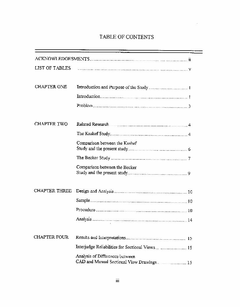
TABLE OF CONTENTS
ACKNOWLEDGESMNTS ...................................
LIST OF TABLES ............................................
CHAPTER ONE
CHAPTER TWO
CHAPTER THREE
CHAPTER FOUR
Introduction and Purpose of the Study ...................
Introduction .................. ... ...............................
Problem ............. ................. .... ... ...................
Related Research ........................................
The K askef Study ....... .... .................................
Comparison between the KashefStudy and the present study.... .....................
The Becker Study ............................... .................
Comparison between the BeckerStudy and the present study ...............................
1
3\
,.4
4
6
7
9
Design and Analysis ................................ .. ...........
Sample ...... ......................................
Procedure ................... .. .............
A nalysis .................... ....... .. ..... . .......................
10
10
10
14
Results and Interpretations .... ........................... 15
Interjudge Reliabilities for Sectional Views......................... 15
Analysis of Differences betweenCAD and Manual Secional View Drawings . ......... .15
iii
ii
v
· ·__
111.11 ... ..................
:: :::

Analysis of Differences betweenCAD and Manual Sectional View Written Test ........ 16
Analysis of Differences betweenCAD and Manual Sectional View Total Time ................... 17
Interjudge Reliabilities fbr Auxiliary Views ............ . 17
Analysis of Differences betweenCAD and Manual Auxiliary View Drawings ................. 18
Analysis of Differences betweenCAD and Manual Auxiliary View Written Test.................... 19
Analysis of Differences betweenCAD and Manual Auxiliary View Total Time ................ 19
Interpretations ..... ............................. ........... 20
CHAPTER FIVE
APPENDIX
Summary and Conclusions ......................... 22
Purpose and Problem of the Study .. .. . .................. 22
Design and Analysis ......... .............. ........... 22
Results .............. .... 23
Conclusions and Recommendations ................................ 23
Appendix A ...... ........................ 25
Appendix B ......... ..........................
A ppendix C ................................................... . . 34
Appendix D ....... 3......................... 36
Appendix E ..................................... ..... 41
Appendix F . . . ............. ........................... 45
Appendix G . ............................... ........... ..... 47
BIBLIOGRAPHY 54
iv

LIST OF TABLES
Table 1 Interjudge Reliabilities for Sectional Views..........................15
Table 2 Means, Standard Deviation, and ANOVASummary for Students Sectional View Drawings.............. 16
Table 3 Means, Standard Devnation, and ANOVASummary for Students Sectional View Written Test :6
Table 4 Means, Standard Deviation, and ANOVASummary for Students Sectional ViewTotal Time to Complete Drawings and Test ...................... 17
Table 5 Interjudge Reliabilities for Auxiliary Views ............... 18
Table 6 Means, Standard Deviation, and ANOVASummary for Students Auxiliary View Drawings ... 18
Table 7 Means, Standard Deviation, and ANOVASummary for Students Auxiliary View Wntten Test... 19
Table 8 Means, Standard Deviation, and ANOVASummary for Students Auxiliary ViewTotal Time to Complete Drawings and Test ..... .... 20
V

Chapter One
Introduction
Drawing is one of the oldest forms of communication, daring back further than
verbal communications. It is a language used to communicate ideas into lines and
symbols, and it has been a useful tool for understanding that which Can not be understood
by the use of verbal communicatlon. I
"Drawings have been developed along two distinct lines; artistic and
technical. The artistic line has artists using drawings to express aesthetic, philosophic, or
other abstract ideas. The technical has people using drawings to represent the design of
objects to be built or constructed." 2 This study will deal with the technical drawing
The first written evidence of the use of technical drawing was in 30 B.C.
when the Roman architect Vitruvius wrote a treatise on architecture in which he said,
"The architect must be skillful with the pencil and have a knowledge of drawing so that he
readily can make the drawings required to show the appearance of lhe work he proposes
to construct.' 3
In order to achieve these drawings a uruversal graphi: language is used.
This language is commonly referred to as drafting. Within the drafting language there are
many
Goetch, D. L., Nelson, I.A., & Chalk, W.S. "Technical Drawing" (2nd Edition)New York: Delmar; 5-12
2 Gcisecke, Fredenick E., MitchelL Alvin Spencer, Henry Cecil, Hill, .van Leroy, & Dygdon,John Thonas. 'TechnicalDrawing" (ighth Editon). ew York: Macmillian 4
3 Giesecke. Frcdenck E., Mitchell, Alvin, Spencer, Henry Cwei, Hill, Ivan Leroy, & Dygdonlohn Thomas. Technical Drawing' (Eighth Edition). NewYork: Macnillian; 5.
l
2
subcategories which include (but are not limited to) the following. technical sketching,
methaaical drawing, engineering drawing, technical drawing, engineerng graphics,
descriptive geometry and computer graphics One may see many of these terms used
interchangeably with the overall term of drafting
The basic principles of drafting are common to both traditional and
computer-aided drafting, In traditional drafting, pencil skills for lettering and line weights
are essential The proper use of hand-held tools and supplies are necessary and vtal to
good results. Computer Aided Drafting (CAD) is an automated process that replaces
drafting tables and hand-held tools It automatically produces consistent lettering and
regulates line work.4
Over the last 20 years, CAD systems have grown steadily in use in architecture,
engineering, construction and other fields. The need for skilled CAD operators is forcing
changes in the drafting curriculum to include computer aided drafting. Education in
drafting has been slow to follow the trend of industry due to the prohibitive cost of the
equipment and software, Recently, costs have become more reasonable
Subsequently, software has become increasingly more powerful, affordable and adaptable
to educational use. This has had a revolutionizing effect on the teaching of drafting.
Many drafting programs may now invest in computers and software which at one time
were priced out of reach.
Although the instruction of the basic principles of drafting are needed for both
manual drafting and computer aided drafting, a debate is currently underway within the
drafting community as to whether to concentrate solely On teaching the new computer
aided drafting skills or whether a umniculum including both methods would be best
As CAD technology has become an essential part of the design process in industry
and education, a debate has also arisen among the concerned trainers as to how students
4 French, Thomas E, Svenson, Carl L., Helsel, Jay D, Urbanick, Broan. "Mcchanical Drawing'(Elcventb Edition) New York: Mamillian, 1990; 4-7
3
can tean and visualize differently with CAD than with traditional methods Resetarits
(1989) believes that students can learn the principles and concepts of drafting by using a
CAD system equally as well as by using traditional drafting tools
This study will try to answer this question by teaching the principles of sectional
views and auxiliary views to secondary students using manual and CAD tools
The Problem
Can drafting techniques and skills such as section view and auxiliaty vew drawings be
comprehended and utilized more effectively by manual or computer assisted draftmg
methods of training ?

Chapter Two
Related Re'search
The Kashef Studys
In 1993, Kashef investigated the effectiveness of computer aided drafting
techniques versus traditional drafting techniques as a method ofteaching pictorial and
multiview drawings. The subjects of the study were thirty-seven full and part-time, male
and female undergraduate students who volunteered to be part of' e study in which they
would be assigned to either the computer aided dranling or traditional drafting section in
an industrial technology course at Montclair State College, New Jersey
The entry level technical drawing course stipulated no prerequisites and
focused on the study ofmultiview and pictorial view drawings. This class met for three
hours each week Two of three intact classes were randomly assigned to either the CAD
group or the traditional drawing section of the study, One class with seventeen students
was assigned to computer aided drafting and the other with twenty students was assigned
to traditional drafting The same instructor was assigned to both classes. Prior to the
expenmental session, each class was given time (six weeks) to learn their respective tools
without exposure to the concept of pictorial and multiview drawings.
The purpose of the study was to determine the effectiveness of two different
methods of teaching multiview and pictorial view drawings. The researcher had six
questions in the study. They are as Follows:
Kashef, Al, (1993). "A comparison ofhe effctivenrss between computer aided drafting andthe traditional drafting tchniques as methods of teaching pictorial and mnltivikw drawings." Paperpresented at th American Vocational Association Convention N'ashvill, TN, December (1993
4

5
I ) Is there a difference in scores acquired on visualization rests that weredeveloped to identify pictorial equivalents of given multiview drawings between studentswho were instructed in beginning technical drafting using CAD and those instructed usingtraditional drafting methods?
2.) Is there a difference in scores acquired on visualization tests that weredeveloped to identify multiview equivalents of given pictorial drawings between studentswho were instructed in beginning technical drafting using CAD and those instructed usingtraditional drafting methods?
3.) Is there a difference in the amount of time required to identify pictorialequivalents of given multiview drawings on visualization rests between students who wereinstructed in beginning technical drafting using CAD and those instructed using traditionaldrafting methods?
4) Is there a difference m the amount of time required to identify multiviewequivalents of given pictorial drawings oP visualization tests between students who wereinstructed in beginning technical drafting using CAD and those instructed using traditionaldrafting methods?
5 ) What is the relationship between test scores and completion time on thepictorial to multiview visualization tests between students who were instructed inbeginning technical drafting using CAD and those instructed using traditional draftingmethods?
6.) What is the relationship between test scores and completion time on themutview to pictorial visualization tests between students who were instructed inbeginning technical drafting using CAD and those instructed using traditional draftingmethods?
A pre-test was developed and validated by a panel of experts which consisted of
three educators of technical drawing and three industry representatives with work
experience in both CAD and traditional drawing. The pretest was given at the beginning
of the seventh week to determine if the two intact groups were equal as to the dependent
variable at the beginning of the instructional program,
The two part instrument consisted of twenty-five questions each. The first part
was designed to measure two dimensional (multiview drawing) to three dimensional
(pictorial drawings) perception and the second part was designed to measure three

6
dimensional to two dimensional perception as they related to the six research questions
The pre test was given the seventh week with a similar post test (questions were
reordered) being administered at twelve weeks.
The researcher found no statistically significant mean di'ferences for problems 1-4.
That is, it was not determined that CAD technique is better than the traditional method or
vice versa The following Pearson correlation coefficients that were used to determine
the relationships between time to complete the rest and score obtained for both the CAD
and traditional classes ranged between 1.) . 1930 & .3795 for the traditional drafting
pretest, 2) .3254 & .4333 on the CAD pro test, 3.) 0.03215 & 2959 for the traditional
drafting post test, and 4.) -. OS32 & .2393 for the CAD post test. 'That is, little practical
significance can be attributed to time to complete a drawing task and pedagogy.
Therefore the two different teaching methods, CAD and traditional, were assumed to be
equally effective for teaching pictorial and multiview drawing.
Conmiadrso between the Ka.shef strud and the presgnt twnrlv
The subjects in the Kashef study were college students in an introductory
technical drawing course. In the present study, the subjects were sccondary students in a
second level mechanical drawing course proficient at not only matching multiview
drawings to pictorial drawings and vice versa, but at drawing both methods of technical
drawing The Kashef study used two separate classes while the present study included
one class and divided the class into two groups
In both studies, students experienced the same instruction without regard to the
tool (computer or drawing instruments) to be used as the same instructor and textbook
were used for both groups.

7
Both studies were designed for understanding differences that could occur
due to pedagogical technique. The Kashef study used a pre-test and post test to measure
correct answers and time as the factors for matching a given multLview drawing (two
dimensional) to a pictorial drawing (three dimensional) to see if the tool enables the
students to better visualize an object. The present study Concentrated on two techniques
commonly used in Technical Drawing (sectional views and auxalary views) to determine if
the tools of the trade enabled students to better process the information that is needed. A
written and drawing test on the information was used for evaluation in the present study.
The Kashef study only had students visualize the different drawings and choose the correct
drawing which best depicts the given view There were no manual drafting or CAD skills
involved. This type of visualization skill could and is commonly taught, at the secondary
level, usig simple sketching techniques.
The Decker Stdv 6
In this 1991 survey study, Becker researched the content and strategies for
teaching computer aided drafting. The primary purpose of the study was to determine
whether selected drafting content should be taught at the seconrdai level using traditional
methods, computer aided methods or both methods.
The Delphi research technique was used m conducting the study "It is a method
of forecasting that uses a panel of experts within a feld to gather consensus on fiture
opportunities, and value judgment."7 The Delpi technique consists of a series of
questionnaires. A three round Delphi was adopted and used for this study.
6 Becker, Kur. "'Content and strategis for teaching computer aided imrating.t Journal of theIndustrial Teachers Education. 2, No 2 (Winter 1991) 38-46
? Somers, K., Baker, G., & Isbell, C (19S4 May). How to use the Delphi Technique to orecasttraining needs. Performance & Instructon Journal, 26-28.

9
The results of the study were unclear due to the following- 1) The goal of
secondary drafting programs were not common, 2 ) Programs have little in common in
both content and equipment, 3 ) Variations in time showed there are no general agreement
on the time needed to master CAD
The study did, however, show a need for a curriculum to be developed to teach
CAD Facilities varied so much that research is needed to establish the optimum
hardware and software to teach CAD in at the secondary level
Comparisnn between the Recker tudv and the pre.sntstudy
The Becker study uses a survey of experts in the teaching of CAD with a focus on
strategies and content of the secondary curriculum. The present study was designed to
understand differences that exist between two aspects of pedagogy for a secondary
mechanical drawing curriculum.
Although the study did not directly influence the present study, some very
important concepts for teaching technical drawing were discussed in the Becker study and
used in the present study The following concepts are important to any technical drawing
program. Wheo teaching CAD, traditional lectures, demonstrations, discussions, and
problems/practices are all effective methods of conveying the information to the students.
CAD instruction should stress concepts and know-how rather than quality and motor
skills. The basic components of sketching, orthographic projection, pictorial projection,
and dimensioning should be taught. CAD and traditional drafting should be
complementary in current drafting programs.
The Becker study and the present study both show that there is a need for CAD in
the curriculum, and also needed is a standardized curriculum, hardware, software, and
facilities in the secondary schools.

Chapter Three
esig aand Analysis
In this study a random sampling of the mechanical drawing students at Triton
Regional High School, Runnemede, New Jersey, was used. The second period class of 17
students was divided into two groups. The students were second year mechanical drawing
students consisting of sophomores, juniors, and seniors, all of whom have successfuly
completed the level one course which included the basics of manual drafting tools and
techniques. The students were from a suburban, middle class, blue collar socioeconomic
area. The ethnic make-up of the group was as follows: one student is Asian male, two are
white females, the remaining 14 are white males.
Procedure
The students in a second level mechanical drawing course wrte required to bgin
the course with a review of manual orthographic projection for the month of September
An orthographic projection is a system of views of an object formed by projectors from
the object perpendicular to the desired planes of projection, this is also referred to as
multivew projection. This system of required views provides for the shape descnption of
the object 8 During this time students completed approximately six drawings using the
orthographic projection method. A written test and a drawing test was given at the end of
this four week period,
I Giesecke, Frederick E., Mitchell, Alvin, Spencer, Henry Cecil, Hill, Ivan Lroy, & Dygdon,John Thomasn "TeclmicalDrawing" (Eighth Edition) New York MVacmiliar 1986: 155.
10

11
At the culmination of this review, the instructor began a tutorial demonstrating the
use of the computer assisted drafting equipment and software. The frst two weeks of this
six week curriculum consisted of lectures and demonstrations with the only manipulations
done by the student being strictly guided by the instructor. The students were introduced
to program menus, the different screens, the multitude of function key operations and the
various control operations. The final four weeks of instruction required the students to
complete the following: 1.) six drawings on their own, 2.) written scantron type test
consisting of sixty questions and 3.) a drawing test graded by the instructor culminating
this section.
The second marking period, which began in early Novembe.r, the students were
introduced to sectional views; this is a technique of drawing internal parts clearly. The
first lesson involved a discussion on the types of sections as follows: full, half, removed,
revolved, broken out, offset, and aligned Each type of section was drawn on the board
and discussed. A piece of fruit was utilized to graphically show the cutting plane and how
the material is to be removed to show the internal parts The second day started with a
review of the types of section views, Multiview drawings with one view missing were
distributed. The students completed the drawing. A discussion of the procedure
followed. The third day reviewed and reinforced the new drawing technique. At the
beginning of the fourth day, the class was randomly divided into two groups The groups
were chosen to proceed in the Manual-CAD group (1) or the CAD-Manual group (2) for
the data collection section ofthis study. For the next four weeks, until the winter recess.
group one completed the assigned section view drawings using the manual tools and
technique. Group two used the computers loaded with Cadkey version 7 to complete
their section drawings. During the fourth week, students were given a written test on
section views The written test for this section was a scantron test of forty questions. The
test is presented in Appendix A The following week, a drawing test consisting of a
12
full section, half section, and an offset section was given to the students Over a two day
period These drawings are presented in appendix B. The drawing test was evaluated
using a point system criteria sheet. This critena sheet presented in Appendix C Scores
from both the multiple choice test and the drawing test served as criterion scores The
completion times, in minutes, were also taken on both the written and drawing tests.
After completion of the evaluations, (early January) the assigned work continued
on section views, however, Manual-CAD group (1) now used the computers and
CAD-Manual group (2) used the manual tools This allo'wed the students to complete
section drawings using both techniques as well as reacquaint the student with the tools
he/she had not been using for the past six weeks.
The next topic to be studied during the last week of January was auxiliary views.
An auxiliary view is a technique used to show the true size and shape of an oblique
surface "The definition is a view obtained by a projection on any plane other than the
horizontal, frontal, and profile projection planes."9 The first week involved the teacher
discussing the classifications, explaining the definition, outlining the process of
construction, and facilitating guided practice of students who sketched auxiliary views.
Each sketch was constructed by the students individually, while two or three randomly
selected students created the view at the board for further clarification by the teacher. The
second week was the start of the individual classwork. The students were assigned six
drawings TO be completed on their own during class time The Manual-CAD
group (1) worked on their auxiliary 'vews using the computer and the CAD-Manual
group (2) used the manual tools to complete their drawings. At the end of the fourth
week, students were given a scantron test of forty multiple choice questions on auxiliary
views. This test is presented in Appendix D. The following week a drawing test
9 Giesecke, Frederick E., Mitchell, Alvin, Spenr, Henry Ccci, ill, Ivan Leroy, &Dygdon, John Thomas "Technical Drawing7 (Eighth Edition). New York: hM'amillan, 198: 231.

13
consisting of three auxiliary views was given. Each group completed this section
of test using the equipment which they had been using. The drawing test is presented in
Appendix E. The drawing test was evaluated using a point system criteria sheet. This
cntena sheet is presented in Appendix F Scores from both the multiple choice test and
the drawing test served as criterion scores. Completion time, in minutes, were also taken
for both tests
After completion of the evaluations, (early March) the assigned work
contmiued on auxiliary views, however, CAD-Manual group (2) now used the computers
and Manual-CAD group (1) used the manual tools This allowed the students to complete
auxiliary drawings using both techniques as well as reacquaint the student with the tools
he/she had not been using for the past six weeks.
The criterion measure sheets used to grade the drawing tests was validated by a
panel of experts. The experts consisted of a college professor and three technology
teachers all of whom have taught section views and auxiliary views.
The judges for both drawing sections consisted of two Temolology teachers and
the researcher, all of whom have experience in teaching Technical Drawing Before the
judges started the judging, the researcher reviewed the drawings and explained the
criterion measure sheet with both judges. During the judging, each student drawing was
compared to a perfect example, Appendix G, prepared by the instructor The instructor
also modified the criterion measure sheet by marking the areas not applicable to each
drawing. The judging averaged one hour per judge to complete.
During the manual drawing portion of the study students used a 24"x 24" drawing
board, 24" T-square, 30-60 triangle, 45 triangle, flat scale, 5mm leadholders, compass,
eraser, eraser shield, brush, French curves, and 11" x 17i vellum. The CAD section had
students using CADKEY version 7.02 software, 486 PC, 33mhz, 16MB ram CPU, super
VGA monitors, and a three button mouse Output was on 11" x 17' white plotter paper
printed from a Hewlett Packard 300XL Paintjet printer.

14
Analys
An interudge reliability was calculated using a Pearson-ProduCt moment
correlation coefficient A least squares one way analysis of variance was used to
determine differences existing in these two one-dimensional designs for differences; one
for the multiple choice test and one for the drawing test.

Chapter 4
Results & Tnterpretaton.s
Setinna View-
Inte.judge Reliahiliirie Interjudge reliabilities among the three judges for each drawing for
sectional views are presented in Table 1, Those interjudge reliabilities range between .733
-927 Overall, there is substantial agreement among all three judges but in particular
between judges 2 & 3
Table IInterjudge Reliabilities of Sectional View Drawings
Drawing Test 1 ... udge 1 - Jude 2Judge 2 0 43Judge 3 0.841 0.894
Drawing Test 2 Judae 1 Judge 2Judge 2 ! 0.S73 i
. Judge 3 1' 0 733 O.S99
Drawing Test 3 Judge 1 . Judge?Judge 2 0784Judge 3 0.828 0.927
Summary of the Analysis of Variance
I_ .. .. DF sMSCGroup 88.432 ss.432Error 3383.097 15 225.540
F F --0,392 11.5.
Drawings Seonal Viesl. Means, Standard Deviations, and ANOVA summary data for
Sectional view drawings are presented in Table 2. The researcher failed to find a
15
I~~~~~~- _ ....

16
statistically significant mean difference between the CAD and manual groups. The
observed mean for the CAD group, however, was higher than the mean for the manual
group.
Table 2Means, Standard Deviation, and ANOVA Summary
for Students Sectional View Drawings
I N M ... SDCAD 9 100.444 14.196
Manual 8 95.875 1.905
Summary of the Analysis of Variance
i SS I DF MS FG poup 1957.765 1 1957.765 1.065n.s.
Error ?272 000 15 183S.800
Written Test eta Viws Means, Standard Deviations, and ANOVA Summary for
Sectional View Written test are presented in Table 3 The researcher failed to find
statistically significant mean difference between the CAD and manual groups.
Table 3Means, Standard Deviation, and ANOVA Sumnary
for Students Sectional View Written Test.
N M SDCADn 9 29 667 3 937
Manual 8 30 750 5.203

17
Summary of the Analysis of Variance
. .. ..... .SS . DF .. MS FGrup 4,971 1 4971 0 633 r
Error 313.500 15 20.900
Total.i Tie ro Complete Sectionna View Dra.wings and Test. Means, Standard Deviations.
and ANOVA Summary data for the Sectional View Written test is -resented in Table 4.
The researcher found a statistically significant mean difference between the amount of time
needed to camplete the drawings and test for the CAD and manual groups The manual
group took less total time to complete the drawings and test.
Table 4Means, Standard Devation, and ANOVA Summary
for Students Sectional View Total Time to complete dravings and Test
N M SDCAD 1 19 487 35 095
Manuals-- .^ -^^ -8 --.8.26 3^-4729 1I Manual I §S 226 14 729
Summary of the Analysis of Variance
_SS DF MS FGroup i 4138.787 1 413S.787 5.4:9*
Error 111372 034 15 758.16
*p<.05
Auxiliary Views.
TntedjiudS Relihailities Interjudge reliabilities among the three judges for each drawing
for auxiliary views are presented in Table 5. Those intejudge reliabilities range between
.860 and .986. Overall, there is substantial agreement among all tee judges but in
particular between judges 2 & 3

18
Table 5latejudge Reliabilities of Auxiliary View Drawings
Drawing Test i .Judge 1 J udge 2Judge 2 0.867
Judge 3 0.92 0.92
Drawg Test 2 Judge 1 Jude 2Judge 2 0 942udge 3 0.945 . 9, .
Drawing Test 3 | Judge I Juge. 2Judge 2 0 916Judge 3 0.912 0 65
Summary of the Analysis ofVariance
SS DF I MS FGroup s8.432 1 88.432 0.392 i.s.
Error 3383.097 1 225.54~~~~~~~~~~~-Irorcl~~~~~~~~~~~~~~~~~~~~~~~~~~~~~~~~~~~~~~~~~~~~~~~~~~~~~~~~~~~~~~~~~~
Orawings Axriliarv Views. Means. Standard Deviation. and ANOVA summary data for
Auxiliary view drawings are presented in Table 6. The researcher failed to find a
statistically significant mean difference between the CAD and manual groups. The
observed mean for the manual group, however, was higher than the mean for the CAD
group.
Table 6Means. Standard Deviation, and ANOVA Sumnary
for Students Auxiliary View Drawings
N M SDCAD 8 9 5 4 125
Manual 9 117 37.699

19
Summary of the Analysis of Variance
SS DF MSC(Toupip 1957.765 1 1957.765 1.065 n.s.
Error 27582 15 1838.8
Wntten Test Adliaer V .ws Means, Standard Deviations, and ANOVA Summary data
for Auxiliary View Written test is presented in Table 7. The researcher failed to find
statistically significant mean difference between the CAD and manual groups
Table 7Means, Standard Deviation, and ANOVA Summary
for Students Auxiliary View Written Test.
N M SDCAD 29 125 4 086
Manual 28.444 3.0[5
Summary of the Analysis of Variance
SS DF MS FGroup 1.962 1 1.962 o0.l ns.
Error 189,097 151 12606 -
Total Time to Complete XDrangs and Test Auxiljar.VJiews. Means, Standard
Deviations, and ANOVA Summary data for Auxiliary View Drawings and Written test is
presented in Table 8. The researcher failed to find a statistically significant mean
difference between the CAD and manual groups.

20
Table 8Means Standard Deviation, and ANOVA Summarv
for Students Auxiliary View Total Completion Time for Drawings and Wrtten Test.
N I M SD--, __ N~ ....... . P A _ SCAD 8 13.475 1 844
Manual 9 14.494 3.400
Summary of the Analysis of Variance
SS DF MS _ FGroup 4.402 4 402 566 ns
Erior 116.742 15 7.783
Interpretation
Intejudge reliabilities were high for both the Sectional Drawings and Auxiliary
Drawings. The Sectional View interjudge reliabilities had an overall lower range (0.733 to
0.927), than the Auxiliary View mtcjudge reliabilities (0.860 to 0 936). Therefore, the
criterion measure which was created and used looks to be a good instrument for the
judging of these drawings. Judges two and three rated the drawings in both sections with
similar ratings. This may be due to the fact that judges two and three are currently
teaching the first two levels of Mechanical Drawing at Triton High School and that judge
one has not taught Mechanical Drawing for at least two years.
The researcher failed to find a mean difference which was statistically sigificant in
the drawing tests for sectional views and auxiliary views, although, the researcher noticed
that the same group of students had higher means scores in both drawing tests. The

21
researcher feels these data indicate that either method, CAD or manual, is an effective
method of teaching technical drawing.
The researcher did detect mean differences that were statistically significant in the
amount of total time required to complete the drawings and test in the sectional view
section of the study. The time was noted as to the time required to complete the drawing
and test only. The time needed to print out a hard copy of each drawing was nor included
for the CAD drawings, due to the researcher only having one printer. The time required
to setup the computer to the printer and create a hard copy output was six minutes per
drawing. If this time was added to both the sectional views and auxiliary view drawings,
the time required to complete each drawing would have been overwhelmingly in favor of
the manual method
For both drawing analyses, the researcher detected mean differences that were not
statistically significant, that could be because the number of students in the experiment
were few, hence contributing to the possibility of a type II error.

Chapter 5
%ixmmary and Conchlsion.s
The Problem
Can drafting techniques and skills such as section view and auxiliary view drawings
be comprehended and utilized more effectively by manual or computer assisted drafing
methods of training ?
Design mlldAMlyis
The sample used for this investigation consisted of the second level Mechanical
Drawing class at Triton Regional High School Runnemede, New Jersey. The second
period class of 17 students was randomly divided into two groups The students were
sophomores, juniors, and seniors, all of whom have successfully completed the level one
course which included the basics of manual drafting tools and techniques. The student
population is primarily white, middle social-economic level.
The researcher, as the teacher, taught the concepts of the two technical drawing
techniques, sectional view and auxiliary view drawings. During each section of the study
one group was assigned to complete drawings using the computer assisted drafting
method and the other group used the manual tools and techniques, The groups switched
methods as the drawing technique changed from sectional view to auxiliary view. Each
group was also given the opportunity to use the CAD or manual method for a week after
the testing was completed for the technique (sectional or auxiliary) being investigated
Testing for each technique consisted of a written scantron test and a drawing test
which had students complete three missing view style drawings. Completion times were
22

23
recorded for written and each drawing test The researcher designed a criterion measure
which was validated by four professionals who teach Technical Drawing. The cnterion
measure was used by three judges, the researcher and two other Technology teachers at
the school. The judges were trained and provided correct examples of each drawing The
combined ratings of the three judges for each technique served as the measure for the data
n the drawing section The students raw score was used for the written scantron test. A
Pearson correlation was calculated on each of the techniques to detenrmie the inteijudge
reliability for the criterion measure. An ANOVA was calculated for the written test
drawing tests, and completion times of each drawing technique to compare the differences
between the CAD and manual drawing methods
Results
lnterjudge reliabilities for both the sectional view and auxiliary view drawings were
very reliable the scores ranged between .733-.927 and .860-.9S6, respectively. Only the
ANOVA for total time was found to be statistically significant. The other five designs
revealed that there is no difference between manual and CAD methods of pedagogy for
teaching second year techrucal drawng students,
Conclusions and Recomendations
Based on the data obtained from this study, it can be concluded that both manual
and CAD are acceptable methods of teaching sectional view and auxiliary view drawings.
The researcher also concludes that the time needed to complete a CAD drawing wdll take
longer, however, drawings may be revised at a much faster rate
Typically technical drawing courses assign a drawing which is completed by the
student and then graded by the teacher. Unfortunately, the student moves on to the next
drawing is never given the opportunity to make the revisions to the drawing for a sense of

24
completion, due to the rime constraints of the curriculum. The CAD method would allow
the student to load the saved drawing, make the revisions quickly, and achieve a sense of
closure for each drawing.
All research points toward the use of CAD for the flture Aerospace engineeing
and designers who have historically been one of the first to use computers as a design tool
have currently created the new Boeing 777 widebody jetliner totally using CAD. The
program called CATIA (Computer Aided Three Dimensional Interactive Application) not
only allows designers to create the parrs in CAD but CATIA also allows the parts to be
assembled within the computer by a computer generated humanoid figure. 0
Future studies should not dwell on whether manual or CAD should be used but on
how to better utilize the CAD software and equipment we have now so we can better
understand how CAD of the future can be implememted to better our society
10 "3-D by desig," The Philrdelnhil Tnqiitet 23 Januan 1997.

APPENDIX
A
25

Section ViewsName: _ Instructor: Mr. Smith
Date. Mechonica DrawnFg II
Read the quoesftot andthepg oilae anrsrs, then print th ielef of fhe onrrct aomwr on the line nex to thequstion If none of the answers are correct use leer (d) none of above. If alT are c.red use lefte (e) all ofthe above
1_ Section views are the method of showing
internal parts ?
2. Section lines are ?
3 _Cutting plane lines are ?
4. A section view which shows a quarter of
the object removed.
5 __ Arrowheads on the cutting plane line
indicate
6. Section lines should be drawn
7. The computer refers to secton lines as
8 The most common spacing of a
section line is
9 A section line can be drawn at
angle?
with hidden lines
clearly
together
Thick dark linesThin dark lines
Medium thin lines
Thick dark lines
Thin dark line
Medium thin lines
Removed section
Full section
Half section
the section rlnes.
the view of the hidden lines.
the way you view the object
parallel,
perpendicular.
horizontal or vertical.
X-hatch
X-crossing
X-view
1/16"1/8"
1/4"30 degrees60 degrees
45 degrees

10. If two materials are to be sectioned it isindicated by
11. The cutting plane line indicates
12. A drawn cutaway view of an object
can be called a
13 __Hidden lines are needed in asectional view
14. How many arrow heads will aHalf-section drawing contain?
i 5 I-low many arrow heads will a
Full-section drawing contain?
16. How many arrow heads will a
Revolved-section drawing contain9
17 _ How many arrow heads will anOffset-section drawing contain?
1. The type of section view where the
interior and exterior are exposed?
19. The type of section view where the
cutting plane line is shown and labeled
but the section is on another page?
a changing the angle or direction
b. changing the thickness.
c. changing the spacing,
a.
b.
c
there will be section view.
the location of the cut
the direction of the cut.
a sectional view
b. cross section
c. section
a.
b.
Or
a.
b.c
always
never
to show clarity
one
two
three
one
two
three
one
two
three
one
two
three
half section
revolved section
removed section
half section
revolved secionremoved section

20_ The type of section view where the
cutting plane line has only one
arrowhead?
21. The type of section view where the
cutting plane line has right angles
but the section does not show it?
22. The type of section view where the
section view has been altered to
clearly show the internal parts?
23. The type of sectional view where the
object is rotated around the center axis?
24 _ Which objects should not be
sectioned ?
25, When drawing section lines care shouldbe taken to make sure the lines are
26 Section views a
b.c
27. The most common type of section
view in engineering drawing ?
a.
b
c.
28. The most common type of section
view in architectural drawing ?
29. In a full section drawing the arrowheads
usually point toward the
30. Sectional views can be drawn in
ar
b.c.
a.
b.c.
a.b.c
half sectionrevolved section
removed section
full sectionaligned sectionoffset section
full section
aligned sectionoffset section
revolved sectionaligned sectionoffset section
nutswebsshafts
evenly spaced.consistent thickness
same angle.
are treated as hidden views.
should be dimensioned as normal.use special dimension techniques.
halffullremoved
half
fullremovedleft
right
it depends on the view
oblique projectionisometric projection
orthographic projection

Carefullv look at the following drawings and read the questions below to each drawing.
PIVOT LIUG A C
A
B --
31. Choose the correct section view for the pivot lug,
it<^.22A B
34. Choose the correct section view.
35 What type of section view is the above?A. Removed B Revolved C. Offset D Aligned E Full
32 Choose the correct section view.
33. What type of section view is the above?A. Removed B. Revolved C. Offset D. Aligned E Full
-I-.
A B C D36. Choose the correct section view.
37. What type of section view is the above?A. Removed B. Revolved COfFset D Aligned E Full
C
38. Choose the corret section view
Using the drawing on the right answer the following.
39. What type of sectional view is it ?A. Removed B. Revolved C. Offset D. Aligned E. Full
40 Which section view is correct for section A-A ?
41 Which section view is correct for section B-B ?
42 Which section view is correct for section C-C ?
B C D EA
!

APPENDIX
B
30
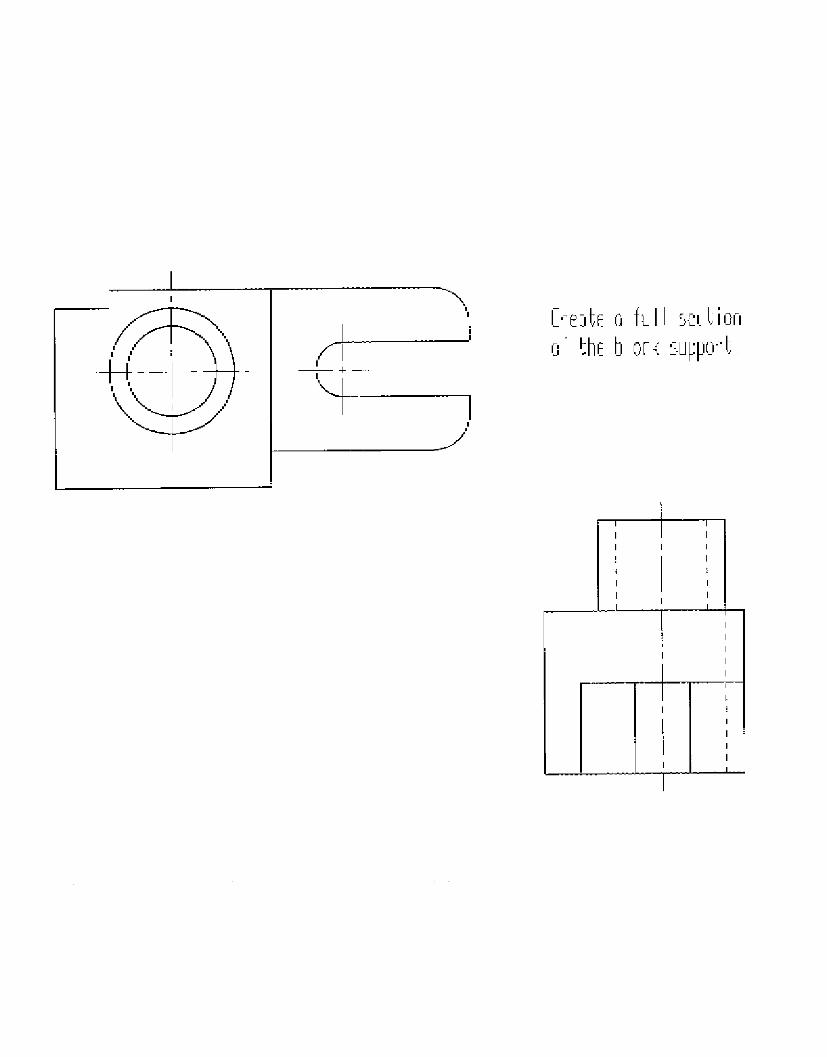
[reAte G ful 5silionoF the b olk support

I : :Ii I I I
i i !I I I I
l I I II ! 1l l l l ,~~~~~~~~~~~~~~~~~~~~~~~~~~~~~~~~~~~~~~~~~~~~~~~~~~~~~~~~~~~~~~~~~~~~~~~~~~~~~~~~~~~~~~~~~~~~~~~~~~~~~~~~~~~~~~~~
'~~~~~- _.
I I.
I IiI I i
I I
I I . II i II I I I
CL ,otr , L r' ci fISt Sct ion
oi l e KJ h. 'pp i r 't

[r;t.7it i iu l Ift set ion iedo1 the quide
., _ . . _ _ - - - - L - _
- - - - - - - - 7 - - - - -I-- - -
. _

APPENDIX
C
34

Section
Students Name:
Criteria QuestionIf yes to the following questions assign threepoints per question. If no assign zero points.N/A if not applicable to the drawing
Is a sketch included?
Is the view drawn correctly?
Is the view sectioned correctly?
d View Drawing Test
Circle the method used: Manual or CAD
Drawing 1 Drawing 2 Drawing 3
F yes to the following questions give two points
Are section lines thin and dark?
Are section lines properly spaced 1/8"?
Axe section lines at the proper angle(nOt parallel or perpendicular to the object line)?
Is the cating plane line dark and thickw;ih proper dashed spacing?
Are the arrowheads on the cutting planeline drawn correctly?
If yes to the following questions give one point.
Are object lines thick and dark?
Are hidden lines thin and darkwith the proper 1/16" space 1/i" dash?
Are center lines thin and dark withthe proper spacing?
Are center lines in the correct position?
Is there proper spacing between views?
Total number of pomts achieved
Total number of possible points
Completion Time.
S.

APPENDIX
D
36

Auxiliary Views
Instructar. Mr. Smrth
MefhaniOcf Drawing 2
Prwnru.
Caerfulty read each quesion and chose the best answer. If none of he answers are correct chAseeKter (D) none of the above If all of the answers are corret chose letter (E) all of te above,
]. We construct auxiliary views to show the
of an object.
2. Auxilary views are also known as
3. The front view is also known as the
4 The top view is also known as the
5. The right side view is also known as the
6. Auxiliary views are classified according to
size and A.
B
C.
views A.
B.
C
true, construction
true, shape
correct, dimensions
common
other
helper
horizontal view
profile view
frontal view
horizontal viewprofile viewfrontal view
horizontal view
profie view
frontal view
A. Length of the incline
B. which plane theyproject from.
C whether the wholeobject is created orjustthe incline.
A.
B,
C,
AB
C.
A
B.C.
Name:
I -11-·
Date:

7 The line of sight A. is perpendicular to theincline surface.
B should be labeled.
C. has an arrowhead thatpoints toward theinchle surface
8. The view which contains the inclined surface
9. The view which contains the third dimensions
A.
B
C.
A.B
C.
10 The line used to transfer measurements and points.
I 1 Another name for an incline surface
12. All objects contain these measurement
A.
B
C.
A.
B
C.
A
B.C.
13 When only the incline surface is shown in the auxiliary view
14. The profile view contain these measurement
A_
C.
A.
B.
C.
15. The horizontal view contain these measurement Ar
B.
C
reference viewprimary view
auxiliary view
reference View
primary view
auxilary view
object linesection line
line of sght
oblique
slanted
angled
length
width
height
half
full
partial
length. width
width, height
height, length
length, width
width, heightheight, length
16 The rontal view contain these measurement A length, width
B. width, heightC height, length
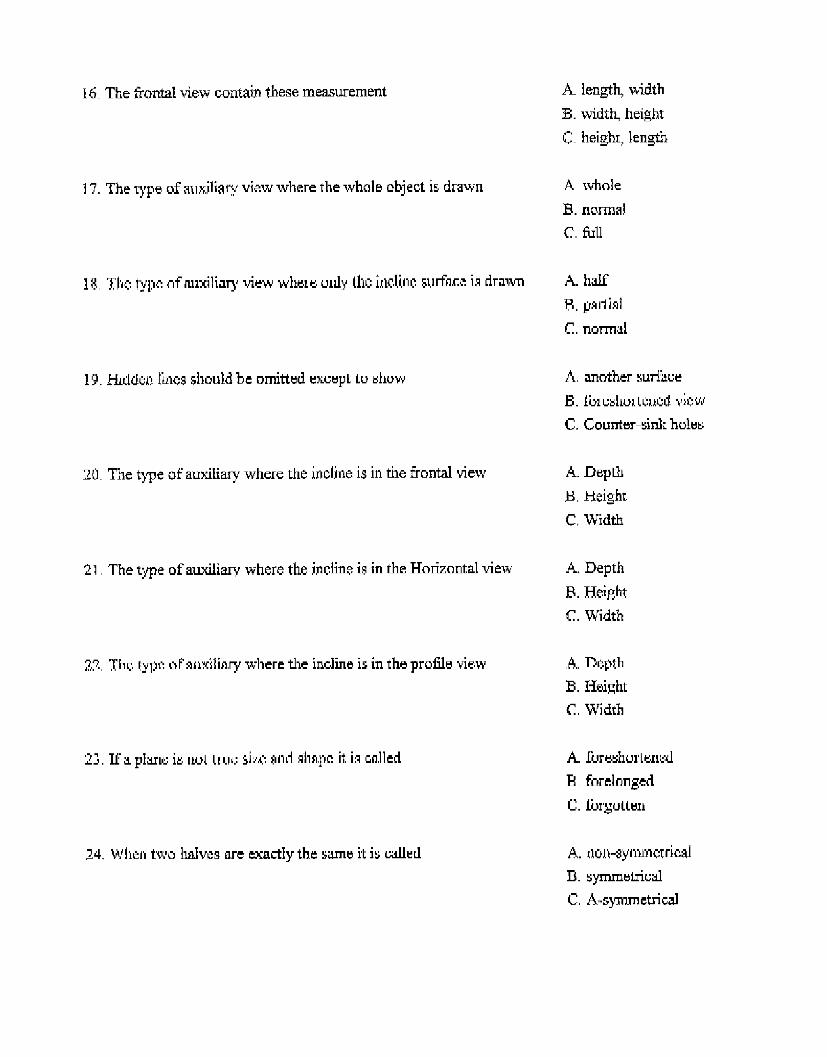
17. The type of auxiliary view where the whole object is drawn
18 The type of auxiliary view where only the incline surface is drawn
A whole
B. normalC. full
A. half
8. partial
C. normal
19. Hidden lines should be omitted except to show A, another surface
B. foreshortened view
C. Counter sink holes
20 The type of auxiliary where the incline is in the frontal view
21. The type of auxiliary where the incline is in the Horizontal view
22 The type of auxiliary where the incline is in the profile view
A. Depth
B. Height
C. Width
A. Depth
B. Height
C. Width
A. Depth
B. Height
C. Width
23. If a plane is not true size and shape it is called A. foreshortened
B forelonged
C. forgotten
24, When two halves are exactly the same it is called A. non-symmetricalB. symmetricalC. A-symmetrical

25. How ar should the reference line in the auxiliary view be
from the inclined surface
Using the statements below organize them in the correct order neededview.
A. two inchesB any convenient distance
C. same as reference vew.
to construct an auxiliary
OuLteions 26-30
A Label the primary and reference views
B. Place an arrowhead on the line pointing toward the incline surface,
C. Examine the views for the incline surface.
D. Label this line the line of sight.
E. Construct a line perpendicular to the incline surface.
Questions 31-35
A Construct projection lines from all points labeled on the primary view perpendicular to the incline
surface.
B. Label the points in the primary view
C Construct a reference line in the reference view.
D. Label the pomts in the reference view
E Construct a reference line parallel to the incline surface m the primary view
Questions 36-40
A, Label the points using the primary and reference views.
B. Darken in the drawing as neededC. Transfer measurements to the auiliary view.
D Connect the points in the proper order.
E. Measure third dimension measurements in the reference views.

APPENDIX
E
41

Ti e to Lonp Ftl: [oQrplele a + u mxil Iry viewNarpl:

Ti r. i Lorplne Eo rip te i0 I ul ux i iG iI; Y E.line:
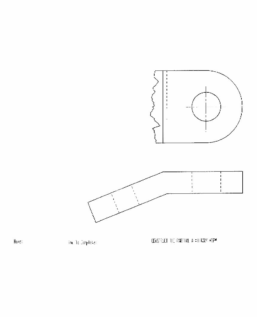
[JSTuiT[I THE PARTIAL MIXlLiAk VIFEHIoe; In i 0 L:-i pIe, ,

APPENDIX
F
45

Auxiliar)
Students Name:
Criteria QuestionIf yes to the following questions assign threepoints per question. If no assign zero points.N/A if not applicable to the drawing
Is the auxlarv view drawn correctly?
Are all points labeled correctly?
y View Drawing Test
Circle the method used: Manual or CAD
Drawing 1 Drawing 2 Drawing 3
f yes to the following questions give two points.
Are the Reference lines present?
Are the Reference lines in the correct place?
Is the Line of Sight present?
Is the Line of Sight drawn correctly(arrowhead & labeled)?
Is the auxiliary view parallel and perpendicularto the incline surface?
1s the primary view labeled correctly?
Is the reference views labeled corretly?
If yes to the following questions give one point.
Are object lines thick and dark?
Are hidden lines thin and darkwith the proper 1/16" space 1/8" dash?
Are center lines thin and dark withthe proper spacing?
Are center lines in the correct position?
Total number of points achieved.
Total number of possible points
Completion Time

APPENDIX
G
47
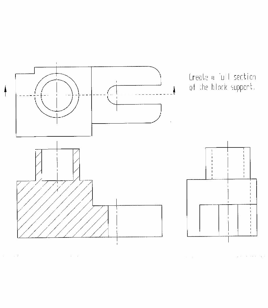
Lrect_ n u I secticrii of t1h h lcK su ppC
- - - I

Lr t nfl u e si ti oi
Of Ine ,Whe .,ppOI ;.

reate CG 'tWf SOcij i uie
of the gouide.
--m
7
Y/l/n
/-///,
IV

R F
3
2,0
F
Ul
N.one:
?2I'l
13,
3,C
L A
\
lin Li [F ] i ELP: aonpmiee a 'ull ouxiliory vie,

2
H
k~Be 1:, ~A
7- I
L A 2,ELA 2.B~~
fib _ 1, 2W
[nrplete o ul I ux i iorv , ei.
Li
EF
(kLF�
jL t i
I
I
I r F1 nX,.I LLI ...
A , ..... . .................................. .

h
6 I
b1
CDiNJSTIUL 1HE PrAi' AIII ' T' e V" E
4
.--- l _ _1
4
Bibiograpdy
Becker, Kurt "Content and strategies for teaching computer aided draftiag."Journal of Industrial Teacher Education 28, No.2 (Writer 19S1); 38-46
Braukmamn, James., Pedras, Melvin. "A comparison of two methods of teachingvsualization skills to college students." Journal of Industrial Teacher Education 30No 2 (Winter I993): 65-80.
Coomber, Brian. "CAD/CAM/CNC and education-organizations tbndging the gap."Technical Directions 53 No.8 (March 1994): 46-47.
Crowl, Thomas K. Fundamentals of education research, Indiana: Brown andBenchmark, 1996.
Duelm, D. F. Computer AidedDrafting llinosis: Goodheart-Wikox, 1989.
Eide, A R, Jensison. R. D., Mashaw, L.H., and Northup, L. L. .ngineeringfundamentals andproblem solving. New York. McGraw-HT-l, 1986,
Flechsig, A- J., Seamans, D. A "Determiing the value of PLATO computer basededucation for a freshran engineering course " Engineerng Educafton 77 No 4(1987). 240-242.
Foster, Robert J. "Traditional engineering graphics versus computer aided drafting: aview from academe." Engineering Design Graphics.Journal 51 No. 1(Winter 1987): 3843.
.French, Thomas, Svenson, Carl L, Helsel, Jay D., and Urbanick, Byron.Mechancal Drawing. New York: McGraw Hill, 1990.
Gerevas, Lawrence E. Drafting Technology Problems 2nd edition. Indiana: Bobs-MerillEducational 1981.
Jhesecke, Frederick E, Mitchell, Alva, Spencer, Henry Cecil, HEIl, Ivan Leroy, Dygeon andJohn Thomas Technical Drawing New York: Macmillian, 1986.
Grayson, L P. The making of an engineer. New York: John Wiley and Sons, 1993.
Hutchinson, John, and Karsnitz, John R. Design andproblem-soving in technology.New York: Delmar, 1994.
54

55
Kashef, All, (1993). "A comparison of the effectiveness between computer aideddrafting and the traditional drafting techniques as methods of teaching pictorial andmultview drawings ' Paper presented at the American Vocational AssociationConvention Nashville ,TN December 1993
Markland, James. "Drawing on Visual Skills." Ties 4 No.1 (Sept./Oct.1991): 31 35
Nee, John G. Engmeering Graphics Problems. New York: Macmillian 1985.
Raudebaugh, Robert. A. 'Manual drafting a skill for the 21st century?`The Technology Teacher 56 No 2 (October 1996)
Resetarist, Pau. J.,and Bertoline, Gary. R. Using Cadkey 2nd edition.New York: Delmar 1991.
Shackelford, Ray L. "Student portfolios. a process/product learmt:g and assesmentstrategy." The Tchnology Teacher 55 No. (May/June 1996)
Smith, Roger. A, "Purchasing computer aided design software" T7he Technology Teacher52 No.2 (November 1992) 7-9
Stinson, Stephen. "Technical program uses advanced instruments" Chemical andEngieering News 59 No. 1 (March 1981): 23-24.
Technology for all Americans Virginia International Technologr Education Association,1996
Volk> Ken 'Necessary skills for high school graduates." he 7echnology Teacher 54No.5 (February 1995): 37-38.

