the client-server model –in this model, the system is structured as a collection of users...
Post on 21-Dec-2015
212 views
TRANSCRIPT

The Client-Server Model
– In this model, the system is structured as a collection of users (clients) and providers (servers) of services.
– This provides more than communication. It gives a structuring to the system.
– It can use a much simpler protocol.• Physical and datalink layers are as normal
(hardware).• All the rest is request/reply protocol.• Client sends a request; server sends a reply.• Less overhead than full OSI.

Clients and Servers
• General interaction between a client and a server.

An Example Client and Server (1)
The header.h file for a trivial file server.

An Example Client and Server (2)
A sample server - typically with infinite loop.

An Example Client and Server (3)
A client using the server to copy a file.
1-27 b

Multitiered Architectures (1)
Alternative client-server organizations (a) – (e).
1-29

Three-tiered Architecture
An example of a server acting as a client.
1-30

Modern Architectures
An example of horizontal distribution of a Web service.
1-31

Client-Server Design Issues
– Addressing the server.• Need to specify the machine that the server is on
and the "process" number.
• Actually it is more common to use the port number.
• Server tells kernel that it wants to listen on this port.
– Can we avoid giving the machine name (location transparency)?
• We could have each server pick a random number from a large space (so the probability of duplicates is low).

Client-Server Design Issues
– When a client wants a service S it broadcasts an I need X and the server supplying X responds with its location.
• So now the client knows the address.
– This first broadcast and reply can be used to eliminate duplicate servers (if desired) and different services accidentally using the same number.
• Another method is to use a name server that has a mapping from service names to locations (and ports).

Client-Server Design Issues
• At startup servers tell the name server their location.
• Is the name server a bottleneck? – We can replicate it and keep it consistent (horizontal
distribution).
– Blocking vs. non-blocking.• Synchronous vs. asynchronous.
• Send and receive synchronous is often called rendezvous.
• Asynchronous send: Do not wait for the message to be received, return control immediately.
– How can you re-use the message variable?

Client-Server Design Issues
• Have the kernel copy the message and then return. This costs performance.
• Don't copy but send an interrupt when message sent. This makes programming harder.
• Offer a system call to tell when the message has been sent.
– Similar to above but "easier" to program. – However it is difficult to guess how often to ask if the
message has been sent.
– Asynchronous Receive: Return control before kernel has filled in message variable with received messages.

Client-Server Design Issues
– How can this be useful?• Wait system call (until message available).• Test system call (has message arrived).• Conditional receive (receive or announce no
message yet).• Interrupt.• None of these is perfect.
– Timeouts• If we have blocking primitives, send or receive
could wait forever.• Some systems/languages offer timeouts.

Client-Server Design Issues
• Buffered vs. unbuffered.– If unbuffered, the receiver tells where to put
the message.• This doesn't work if an asynchronous send is done
before the receive (where does the kernel put the message?).
– For buffered, the kernel keeps the message (in a mailbox) until the receiver asks for it.
• This raises buffer management questions.

Client-Server Design Issues
• Reliable vs. Unreliable Primitives– We can define the send primitive to be
unreliable.• Error checking is done at a higher level.
– Kernel can acknowledge every message.• Senders and repliers keep message until they receive
an ack.
– Kernel can use reply to ack every request but explicitly ack replies.

Client-Server Design Issues
– Kernel can use reply as ack to every request but not ack replies.
• Client will resend request if the reply doesn’t reply in time.
• Not always good (e.g. if server had to work hard to calculate reply).
– Kernel at server end can deliver request and send ack if reply not forthcoming soon enough.
• Again it can either ack the reply or not.

The Client-Server Model

Layered Protocols
– As we saw previously, network software is often structured as a layered protocol suite. We will now examine these protocols in somewhat more detail.
– Protocol: An agreement between communicating parties on how communication is to proceed.
• Error correction codes.
• Blocksize.
• Ack/Nak.

Layered Protocols
– Layered protocol: The protocol decisions concern very different things
– How many volts is 1 or zero? How wide is the pulse? (low level details)
• Error correction
• Routing
• Sequencing (higher level details)
– As a result you have many routines that work on the various aspects. They are called layered.

Layered Protocols
– Layer X of the sender acts as if it is directly communicating with layer X of the receiver but in fact it is communicating with layer X-1 of the sender.
– Similarly layer X of the sender acts as a virtual layer X+1 of the receiver to layer X+1 of the sender.
– A famous example is the ISO OSI (International Standards Organization Open Systems Interconnection Reference Model).
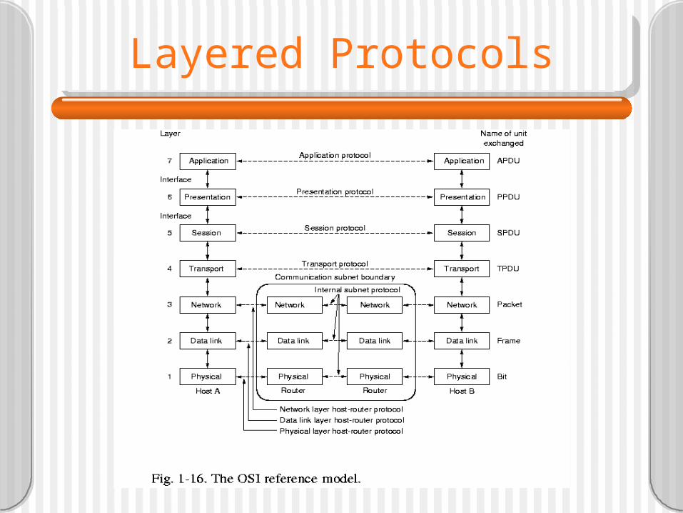
Layered Protocols

Layered Protocols
– So for example the network layer sends messages intended for the other network layer but in fact sends them to the data link layer.
– Also the network layer must accept messages from the transport layer, which it then sends to the other network layer (really its own data link layer.
• What a layer really does to a message it receives is add a header (and maybe a trailer) that is to be interpreted by its corresponding layer in the receiver.

Layered Protocols
– So the network layer adds a header (in front of the transport layer's header) and sends to the other network layer (really its own data link layer that adds a header in front of the network layer's and a trailer).
– So headers get added as you go down the sender's layers (often called the Protocol Stack or Protocol Suite).
– They get used (and stripped off) as the message goes up the receiver's stack.

Layered Protocols

Layered Protocols
– It all starts with process A sending a message. By the time it reaches the wire it has 6 headers (the physical layer doesn't add one - Why?) and one trailer.
• The nice thing is that the layers are independent. You can change one layer and not change the others.
– Physical layer: hardware, i.e. voltages, speeds, connectors.
– Data link layer: Error correction and detection. "Group the bits into units called frames".

Layered Protocols
• Frames contain error detection (and correction) bits.• This is what the pair of data link layers do when
viewed as an extension of the physical.• But when being used, the sending DL layer gets a
packet from the network layer and breaks it into frames and adds the error detection bits.

Data Link Layer
Discussion between a receiver and a sender in the data link layer.
2-3

Layered Protocols
– Network layer: Routing.• Connection oriented network-layer protocol: X.25
or ATM. – Send a message to destination and establish a route that
will be used for further messages during this connection (a connection number is given).
– Like a telephone call.
• Connectionless: IP (Internet Protocol). – Each packet (message between the network layers) is
routed separately. – Like the post office.

What is ATM ?
• Asynchronous Transfer Mode (ATM):– Is a connection-oriented lower-level
communications technology which can perform at very high speeds.
• ATM is integration of multiple media types:– Data– Voice– Video– Images

ATM Networks
– ATM newer than TCP/IP• The hardware is better (newer) and has much higher
data rates than previous long haul networks.
• 155Mbits/sec compared to T3=45Mb/s is the low end. 622Mb/sec is midrange.
– In pure circuit switching a circuit is established and held (reserved) for the duration of the transmission.
– In store and forward packet switching, go one hop at at time with entire packet.

ATM Networks
– ATM establishes a circuit but it is not (exclusively) reserved.
• Instead the packet is broken into smallish fixed-sized cells.
• Cells from different transmissions can be interleaved on same wire.
– ATM has its own protocol hierarchy, separate from TCP/IP.
– It is meant to be used for both voice/data and unicast/multicast.

ATM Networks

Circuit vs. Packet Switching:
• Circuit:– End-to-end connection.– Constant delay.– Information is delivered in order (sequenced
delivery).– Network is transparent to the user’s
information.– May be inefficient for some types of traffic.

Circuit vs. Packet Switching:
• Virtual Circuit:– End-to-end connection in a packet switched
network.– Packets delivered in order.– Network is not transparent to what the user is
sending.– More efficient than circuits for certain
applications.

Connection-Oriented(Virtual Circuit)
Connection-less(Datagram)
Preplanned route establishedbefore any packets are sent(call setup)
No call setup required andeach packet is treatedindependently
Fixed route for logicalconnection duration
Routing decision made foreach packet
Network may provide services(sequencing & error control)
Packet can arrive out of order
Most current packet switchednetworks use virtual circuits
Can implement a flexibleapproach to congestion(rerouting)

Old Lower-Layers Model:OSI
# DTE DCE nodes DTE4..7 Higher Layers Higher Layers3 Network Network Network2 Data Link Data Link Data Link1.5 MAC sublayer MAC sublayer MAC sublayer1 Physical Physical Physical
DTE - Data Terminating Equipment
DCE - Data Carrier Equipment.
Original BER - Bit Error Rate = 10-5 (1970s)

New Lower-Layers Model:ATM
# DTE DCE nodes DTE4..7 Higher Layers Higher Layers3 Network Network2 AAL AAL1.5 ATM ATM ATM1 SONET/ATM SONET SONET/ATM
New BER - Bit Error Rate = 10-11 or 10-12

ATM Adaptation Layer:
• ATM transfers cells. Applications that transfer data over ATM do not read or write cells.
• Higher-layer protocols interact with ATM through the ATM Adaptation Layer (AAL).
• AAL performs many functions including:– Detection and correction of errors.– Multiplexing and Demultiplexing of data units.– Lost or corrupted cells.

ATM Adaptation Layer:Service Classes
• Service Classes:– Class A - Circuit emulation; constant bit rate– Class B - Variable bit rate; audio and video– Class C - Connection-oriented data transfer;
variable bit rate (Frame Relay, TCP/IP)– Class D - Connectionless data transfer– Class X - Connection-oriented; best-effort
delivery; user regulated.

ATM Adaptation Layer:Protocols
• AAL Protocols:– AAL1 = Class A– AAL2 = Class B– AAL3/4, 5 = Class C– AAL3/4, 5 = Class D– AAL3/4, 5 = Class X– AAL0 = Null

IP Address Binding in ATM:
• We can run TCP/IP on top of ATM.• Encapsulating a datagram over ATM is
straight forward, however address binding is difficult.
• ATM assigns addresses to all machines wishing to use a virtual circuit.
• ATM physical addresses are larger than IP addresses, so they cannot be encoded within them as static bindings.

IP Address Binding in ATM:
• ATM does not support broadcasting (only multicasting via meta-signaling), therefore IP cannot use ARP for address resolution.

Layered Protocols
– Transport layer: make reliable and ordered (but not always).
• Break incoming message into packets and send to corresponding transport layer (really send to ...). They are sequence numbered.
• Header contains info as to which packets have been sent and received.
• These sequence numbers are for the end to end message.

Layered Protocols
• I.e. if grail.cba.csuohio.edu sends message to www.microsoft.com the transport layer breaks message into packets and numbers the packets.
– These packets may take different routes.
– On any one hop the data link layer keeps the frames ordered.
• If you use connection-oriented network layer there is little for transport layer to do.
• If you use IP for network layer, there is a lot to do.
• If use connection-oriented TCP for transport layer of client-server system, slower than need be
– Can use transactional TCP

Client-Server TCP
a) Normal operation of TCP.b) Transactional TCP.
2-4

Layered Protocols
– Session Layer: dialog and synchronization.• Dialog control
• Synchronization facilities
– Presentation layer: Describes "meaning" of fields.• Record definition
– Application layer: For specific applications (e.g. mail, news, ftp).
• Middleware logically resides in the application layer, but contains functionality that is quite general
– Authentication
– Authorization
– Multicast, etc.
• This leads to a slightly modified reference model

Middleware Protocols
An adapted reference model for networked communication.
2-5