the class v underground injection control study volume 21
TRANSCRIPT
United States Office of Ground Water EPA/816-R-99-014uEnvironmental and Drinking Water (4601) September 1999Protection Agency
The Class V Underground InjectionControl Study
Volume 21
Aquifer Recharge and Aquifer Storageand Recovery Wells
September 30, 1999
Table of Contents
Page1. Summary . . . . . . . . . . . . . . . . . . . . . . . . . . . . . . . . . . . . . . . . . . . . . . . . . . . . . . . . . . . . . . 1
2. Introduction . . . . . . . . . . . . . . . . . . . . . . . . . . . . . . . . . . . . . . . . . . . . . . . . . . . . . . . . . . . . 2
3. Prevalence of Wells . . . . . . . . . . . . . . . . . . . . . . . . . . . . . . . . . . . . . . . . . . . . . . . . . . . . . . 4
4. Injectate Characteristics and Injection Practices . . . . . . . . . . . . . . . . . . . . . . . . . . . . . . . . 84.1 Injectate Characteristics . . . . . . . . . . . . . . . . . . . . . . . . . . . . . . . . . . . . . . . . . . . . . 8
4.1.1 Aquifer Recharge Wells . . . . . . . . . . . . . . . . . . . . . . . . . . . . . . . . . . . . . . . 84.1.2 ASR Wells . . . . . . . . . . . . . . . . . . . . . . . . . . . . . . . . . . . . . . . . . . . . . . . . 15
4.2 Well Characteristics . . . . . . . . . . . . . . . . . . . . . . . . . . . . . . . . . . . . . . . . . . . . . . . 274.2.1 Design Features . . . . . . . . . . . . . . . . . . . . . . . . . . . . . . . . . . . . . . . . . . . . 274.2.2 Siting Considerations . . . . . . . . . . . . . . . . . . . . . . . . . . . . . . . . . . . . . . . . 29
4.3 Operational Practices . . . . . . . . . . . . . . . . . . . . . . . . . . . . . . . . . . . . . . . . . . . . . . 31
5. Potential and Documented Damage to USDWs . . . . . . . . . . . . . . . . . . . . . . . . . . . . . . . 325.1 Injectate Constituent Properties . . . . . . . . . . . . . . . . . . . . . . . . . . . . . . . . . . . . . . 325.2 Observed Impacts . . . . . . . . . . . . . . . . . . . . . . . . . . . . . . . . . . . . . . . . . . . . . . . . . 33
6. Best Management Practices . . . . . . . . . . . . . . . . . . . . . . . . . . . . . . . . . . . . . . . . . . . . . . . 336.1 Aquifer Recharge and ASR Wells . . . . . . . . . . . . . . . . . . . . . . . . . . . . . . . . . . . . 33
6.1.1 Recharge Water Quality . . . . . . . . . . . . . . . . . . . . . . . . . . . . . . . . . . . . . . 336.1.2 Water Monitoring in Recharge Projects . . . . . . . . . . . . . . . . . . . . . . . . . . 346.1.3 Physical, Biological, Chemical, and Mechanical Clogging . . . . . . . . . . . 34
6.2 ASR Wells . . . . . . . . . . . . . . . . . . . . . . . . . . . . . . . . . . . . . . . . . . . . . . . . . . . . . . 376.2.1 Location and Spacing of ASR Wells and Impact on Static
Ground Water Levels . . . . . . . . . . . . . . . . . . . . . . . . . . . . . . . . . . . . . . . . 376.2.2 Operation and Maintenance Practices for ASR Wells . . . . . . . . . . . . . . . 37
7. Current Regulatory Requirements . . . . . . . . . . . . . . . . . . . . . . . . . . . . . . . . . . . . . . . . . . 387.1 Federal Programs . . . . . . . . . . . . . . . . . . . . . . . . . . . . . . . . . . . . . . . . . . . . . . . . . 38
7.1.1 SDWA . . . . . . . . . . . . . . . . . . . . . . . . . . . . . . . . . . . . . . . . . . . . . . . . . . . 387.1.2 Other Federal Rules and Programs . . . . . . . . . . . . . . . . . . . . . . . . . . . . . 40
7.2 State and Local Programs . . . . . . . . . . . . . . . . . . . . . . . . . . . . . . . . . . . . . . . . . . 42
Attachment A: ASR Well Data Reported in Literature . . . . . . . . . . . . . . . . . . . . . . . . . . . . . . . . 45
Attachment B: ASR Facilities and Wells in Florida . . . . . . . . . . . . . . . . . . . . . . . . . . . . . . . . . . 47
Attachment C: State and Local Program Descriptions . . . . . . . . . . . . . . . . . . . . . . . . . . . . . . . . 49
References . . . . . . . . . . . . . . . . . . . . . . . . . . . . . . . . . . . . . . . . . . . . . . . . . . . . . . . . . . . . . . . . . . 66
Aquifer recharge and ASR well injecting only treated wastewater are addressed separately in1
the sewage treatment effluent well summary, which is Volume 7 of the Class V UIC Study.
September 30, 1999 1
AQUIFER RECHARGE AND AQUIFER STORAGE AND RECOVERY WELLS
The U.S. Environmental Protection Agency (USEPA) conducted a study of Class Vunderground injection wells to develop background information the Agency can use to evaluatethe risk that these wells pose to underground sources of drinking water (USDWs) and todetermine whether additional federal regulation is warranted. The final report for this study,which is called the Class V Underground Injection Control (UIC) Study, consists of 23 volumesand five supporting appendices. Volume 1 provides an overview of the study methods, theUSEPA UIC Program, and general findings. Volumes 2 through 23 present informationsummaries for each of the 23 categories of wells that were studied. This volume, which isVolume 21, covers two Class V well categories: aquifer recharge and aquifer storage andrecovery (ASR) wells.
1. SUMMARY
Aquifer recharge and ASR wells are used to replenish water in an aquifer for subsequentuse. While an aquifer recharge well is used only to replenish the water in an aquifer, ASR wellsare used to achieve two objectives: (1) storing water in the ground; and (2) recovering the storedwater (from the same well) for a beneficial use. Both of these types of wells, however, may havesecondary objectives, such as subsidence control and prevention of salt water intrusion into freshwater aquifers. Aquifer recharge and ASR wells are found in areas of the U.S. that have highpopulation density and proximity to intensive agriculture; dependence and increasing demand onground water for drinking water and agriculture; and/or limited ground or surface wateravailability. ASR wells are also found in areas that have no freshwater drinking water supplies,or in coastal areas where salt water intrusion into freshwater aquifers is an issue.
Aquifer recharge and ASR well injectate consists of potable drinking water (from adrinking water plant), ground water (treated or untreated), and surface water (treated oruntreated). Water injected into aquifer recharge and ASR wells is typically treated to meet1
primary and secondary drinking water standards. This is done to protect the host aquifer and toensure that the quality of the ground water to be recovered is adequate for subsequent use. Inaddition, most regulatory agencies require the injectate in aquifer recharge and ASR wells tomeet drinking water standards in order to prevent degradation of ambient ground water quality. However, it should be noted that, in some instances, constituents have been measured atconcentrations slightly above drinking water standards.
Aquifer recharge and ASR wells are drilled to various depths depending on the depth ofthe receiving aquifer. They may inject into confined, semi-confined, or unconfined aquifers,although most of these wells inject into semi-confined aquifers that have been partiallydewatered due to overpumping.
September 30, 1999 2
No contamination incidents associated with the operation of aquifer recharge or ASRwells have been reported.
Because the major goal of aquifer recharge and ASR wells is to replenish water inaquifers for subsequent use and its injectate typically meets drinking water standards, aquiferrecharge and ASR wells are unlikely to receive spills or illicit discharges.
According to the state and USEPA Regional survey conducted for this study, there areapproximately 1,185 aquifer recharge and ASR wells documented in the U.S. This total includes807 aquifer recharge wells, 130 ASR wells, and 248 wells (in California and Idaho) that cannotbe distinguished among aquifer recharge and ASR wells in the available inventory. Theestimated number of aquifer recharge and ASR wells in the nation is greater than 1,695, butunlikely to be higher than 2,000. This estimate does not include 200 wells proposed to be builtin Florida as part of the "Everglades Restoration Project." Approximately 89 percent of thedocumented aquifer recharge and ASR wells are located in ten states: California (200),Colorado (9), Florida (<488), Idaho (48), Nevada (110), Oklahoma (44), Oregon (16), SouthCarolina (55), Texas (67), and Washington (12). Wisconsin has conditionally approved oneASR well as part of a pilot study at a municipal water system in Oak Creek, and a second pilotproject in Green Bay, Wisconsin is under development. The project in Green Bay is expected tobe operational within the next year.
The statutory and regulatory requirements differ significantly among the ten states wherethe majority of the aquifer recharge and ASR wells are believed to exist. In California andColorado, USEPA Regions 9 and 8, respectively, directly implement the UIC program for ClassV injection wells. However, both states have additional jurisdiction over aquifer recharge andASR wells through state regional water quality control boards in California and permitting ofextraction and use of waters artificially recharged in Colorado. The remaining eight states areUIC Primacy States for Class V wells. Oklahoma and Texas are UIC Primacy States thatauthorize aquifer recharge and ASR wells by rule, while Florida, Nevada, Oregon, SouthCarolina, and Washington require individual permits for the operation of aquifer recharge andASR wells. In Idaho, construction and operation of shallow injection wells (<18 feet) isauthorized by rule; construction and use of a deep injection well ($18 feet) requires an individualpermit.
2. INTRODUCTION
Ground water is being increasingly used for agricultural, drinking, and industrial suppliesin the United States. As a result, the available supply of fresh ground water is decreasing at anaccelerated rate, and water managers and planners have been faced with the challenge ofdeveloping water management techniques to meet water demands (O'Hare et al., 1986; Pyne,1995).
One technique that has been used in recent years is artificial aquifer recharge. Artificialrecharge refers to the movement of water via man-made systems from the surface of the earth tounderground water-bearing strata where it may be stored for future use (Griffis, 1976). Suchrecharge may be conducted for ground water resource management, water storage and recovery,
September 30, 1999 3
prevention of salt water intrusion into fresh water aquifers, and subsidence control, among otherpurposes (Bouwer et al., 1990; Crook et al., 1991; Fairchild, 1985; Hamlin, 1987; North CarolinaDivision of Water Resources, 1996).
The advantages of aquifers over surface water impoundments as reservoirs for cyclicstorage of water are: (1) permanence; (2) no loss of storage capacity due to sedimentation; (3) noloss of water due to evaporation; (4) less vulnerability to destruction and contamination; and (5)the absence of threat to downstream communities (by eliminating the possibility of damsbreaking and floods occurring) (Kazmann, 1967).
Conventional methods of artificial recharge include surface spreading, infiltration pitsand basins, and injection wells. Injection wells are the selected method of artificial recharge inareas where the existence of impermeable strata between the surface and the aquifer makesrecharge by surface infiltration impractical or in areas where land for surface spreading islimited.
During the last 30 years, a special type of recharge well has been developed: ASR wells(Wilson, 1999; Pyne, 1995). What distinguishes an ASR well from an aquifer recharge well isits dual-purpose characteristic. While an aquifer recharge well is used only to replenish thewater in an aquifer, ASR wells are used to achieve two objectives: (1) storing water in theground; and (2) recovering the stored water (from the same well) for a beneficial use.
This summary addresses both aquifer recharge and ASR wells. These types of wellsusually inject water into water supply aquifers. According to the existing UIC regulations in 40CFR 146.5(e)(6), “recharge wells used to replenish the water in an aquifer” are considered ClassV injection wells. ASR wells are considered Class V injection wells under the existing UICregulations in 40 CFR Parts 144 and 146, but ASR wells are not specifically defined in theregulations.
Aquifer recharge and ASR wells that only inject reclaimed wastewaters are addressedseparately in the sewage treatment effluent well summary, which is Volume 7 of the Class VUIC Study (the wells covered in this volume, Volume 21, do not inject sewage treatment effluentor inject such effluent mixed with ground water and/or surface water). Aquifer recharge wellsused primarily for subsidence control or prevention of salt water intrusion into fresh wateraquifers are addressed in Volumes 20 and 23 of the Class V UIC Study, respectively.
Connector wells, which create a direct connection, or bore hole, from one aquifer toanother, are designed to drain surficial aquifers into a deeper aquifer and are used solely fordewatering purposes, not in a recharge capacity. Thus, connector wells are considered specialdrainage wells and are not included in this volume. For further information on connector wells,see the special drainage information summary, which is Volume 14 of the Class V UIC Study. Storm drainage wells, which may provide aquifer recharge while disposing of excess stormwater, are addressed separately in Volume 3 of the Class V UIC Study.
September 30, 1999 4
3. PREVALENCE OF WELLS
The primary factors for locating aquifer recharge and ASR wells include: populationdensity and proximity to intensive agriculture in a low moisture region; dependence andincreasing demand on ground water for drinking water and agriculture; high seasonalfluctuations in water demand and availability; and limited ground or surface water availability. ASR wells are also found in areas that have no fresh water drinking water supply, or in coastalareas where salt water intrusion into freshwater aquifers is an issue. Densely developed areastend to use recharge wells, while the Central and Western Plains States have more available openland and are more likely to use recharge basins and infiltration areas. As the population grows,as adequate land for the construction of surface reservoirs becomes increasingly scarce, and aswater sources become more limited, the use of aquifer recharge and ASR wells is expected toincrease.
Three studies looked at potential siting and future needs for artificial aquifer recharge. Culp (1981) developed water use and ground water mining projections for areas of the countryand identified the Great Plains and the southwest United States as requiring recharge or someother action to alleviate water shortages. O’Hare et al. (1986) used a model based on agricultureneeds to identify areas for aquifer recharge. The model identified central areas of the GreatPlains and areas along the west and southeastern coasts of the United States. Fairchild (1985)identified areas suitable for aquifer recharge in combination with a need for preventing salt waterintrusion. The areas suitable for recharge, according to Fairchild, corresponded to the sameareas identified by O’Hare (1986): central areas of the Great Plains and areas along the west andsoutheastern coasts of the United States.
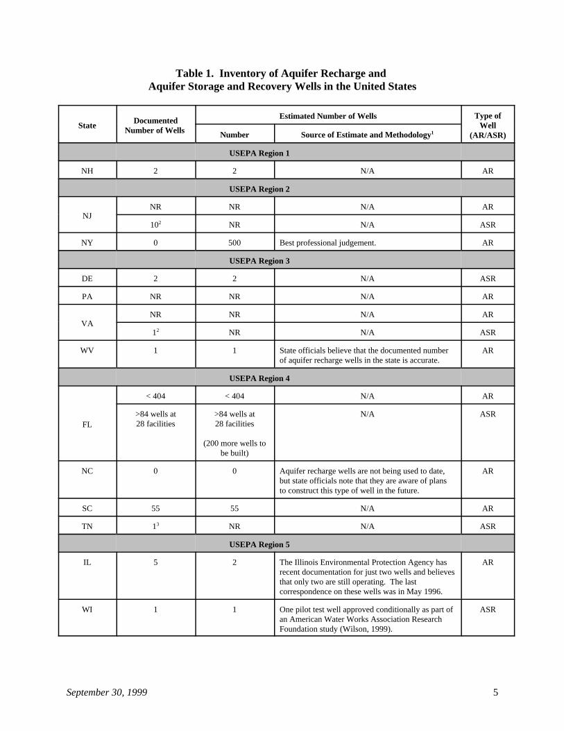
For this study, data on the number of Class V aquifer recharge and ASR wells werecollected through a survey of state and USEPA Regional UIC Programs. The survey methodsare summarized in Section 4 of Volume 1 of the Class V UIC Study. Table 1 lists the numbersof Class V aquifer recharge and ASR wells in each state, as determined from this survey. Thetable includes the documented number and estimated number of wells in each state, along withthe source and basis for any estimate, when noted by the survey respondents. If a state is notlisted in Table 1, it means that the UIC Program responsible for that state indicated in its surveyresponse that it did not have any Class V aquifer recharge or ASR wells.
As shown in Table 1, there are approximately 1,185 aquifer recharge and ASR wellsdocumented in the United States. This total includes 807 aquifer recharge wells, 130 ASR wells,and 248 recharge wells (in California and Idaho) that cannot be distinguished among aquiferrecharge and ASR wells in the available inventory. The estimated number of aquifer rechargeand ASR wells in the nation is believed to be greater than 1,695 (1,300 aquifer recharge wells,147 ASR wells, and the 248 wells in California and Idaho that are either aquifer recharge or ASRwells. These estimates include 404 in Florida that were reported as aquifer recharge wells. However, there is a possibility that a high number of these 404 wells are storm drainage wells or
September 30, 1999 5
Table 1. Inventory of Aquifer Recharge and Aquifer Storage and Recovery Wells in the United States
State WellDocumented
Number of Wells
Estimated Number of Wells Type of
(AR/ASR)Number Source of Estimate and Methodology1
USEPA Region 1
NH 2 2 N/A AR
USEPA Region 2
NJNR NR N/A AR
10 NR N/A ASR2
NY 0 500 Best professional judgement. AR
USEPA Region 3
DE 2 2 N/A ASR
PA NR NR N/A AR
VANR NR N/A AR
1 NR N/A ASR2
WV 1 1 State officials believe that the documented number ARof aquifer recharge wells in the state is accurate.
USEPA Region 4
FL
< 404 < 404 N/A AR
>84 wells at >84 wells at N/A ASR28 facilities 28 facilities
(200 more wells tobe built)
NC 0 0 Aquifer recharge wells are not being used to date, ARbut state officials note that they are aware of plansto construct this type of well in the future.
SC 55 55 N/A AR
TN 1 NR N/A ASR3
USEPA Region 5
IL 5 2 The Illinois Environmental Protection Agency has ARrecent documentation for just two wells and believesthat only two are still operating. The lastcorrespondence on these wells was in May 1996.
WI 1 1 One pilot test well approved conditionally as part of ASRan American Water Works Association ResearchFoundation study (Wilson, 1999).
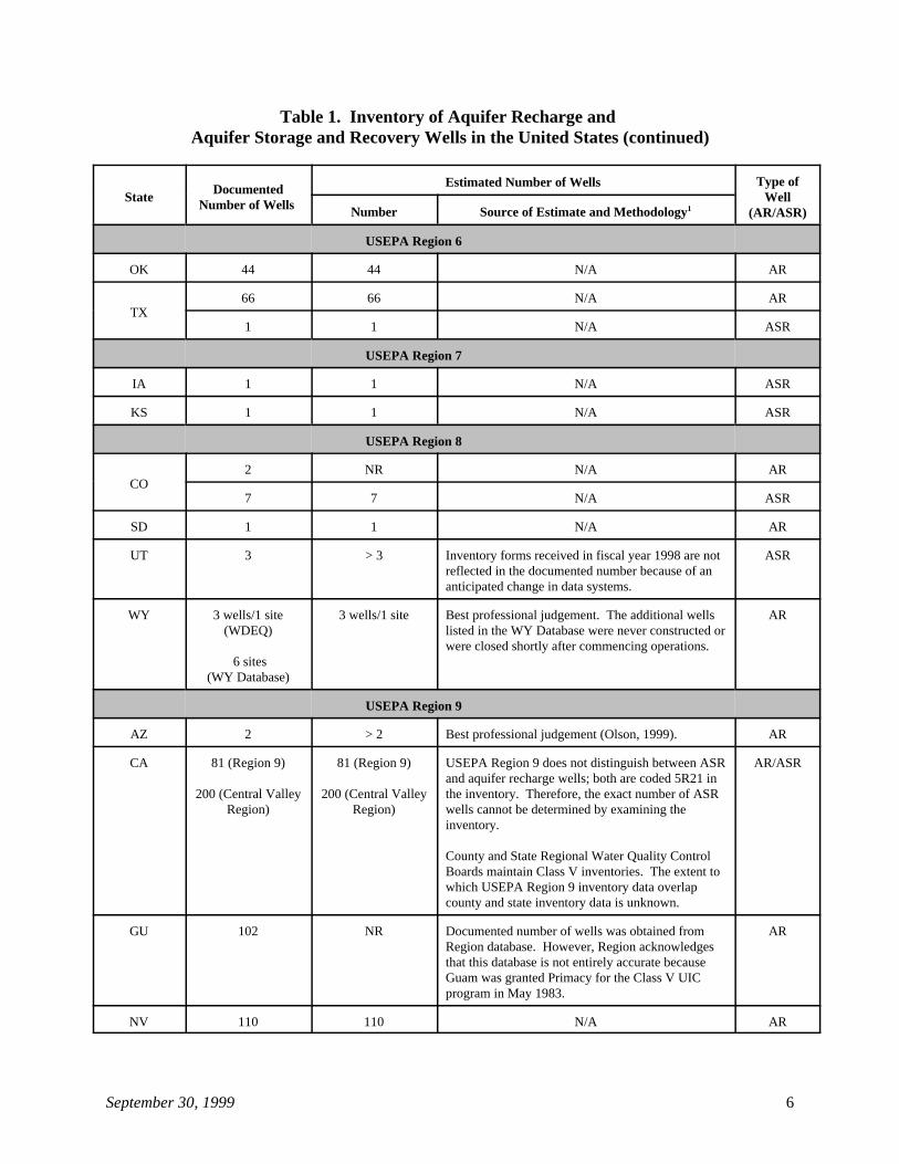
Table 1. Inventory of Aquifer Recharge and Aquifer Storage and Recovery Wells in the United States (continued)
State WellDocumented
Number of Wells
Estimated Number of Wells Type of
(AR/ASR)Number Source of Estimate and Methodology1
September 30, 1999 6
USEPA Region 6
OK 44 44 N/A AR
TX66 66 N/A AR
1 1 N/A ASR
USEPA Region 7
IA 1 1 N/A ASR
KS 1 1 N/A ASR
USEPA Region 8
CO2 NR N/A AR
7 7 N/A ASR
SD 1 1 N/A AR
UT 3 > 3 Inventory forms received in fiscal year 1998 are not ASRreflected in the documented number because of ananticipated change in data systems.
WY 3 wells/1 site 3 wells/1 site Best professional judgement. The additional wells AR(WDEQ) listed in the WY Database were never constructed or
6 sites (WY Database)
were closed shortly after commencing operations.
USEPA Region 9
AZ 2 > 2 Best professional judgement (Olson, 1999). AR
CA 81 (Region 9) 81 (Region 9) USEPA Region 9 does not distinguish between ASR AR/ASR
200 (Central Valley 200 (Central Valley the inventory. Therefore, the exact number of ASRRegion) Region) wells cannot be determined by examining the
and aquifer recharge wells; both are coded 5R21 in
inventory.
County and State Regional Water Quality ControlBoards maintain Class V inventories. The extent towhich USEPA Region 9 inventory data overlapcounty and state inventory data is unknown.
GU 102 NR Documented number of wells was obtained from ARRegion database. However, Region acknowledgesthat this database is not entirely accurate becauseGuam was granted Primacy for the Class V UICprogram in May 1983.
NV 110 110 N/A AR
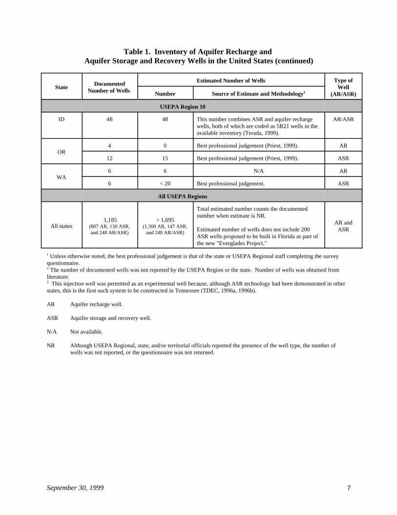
Table 1. Inventory of Aquifer Recharge and Aquifer Storage and Recovery Wells in the United States (continued)
State WellDocumented
Number of Wells
Estimated Number of Wells Type of
(AR/ASR)Number Source of Estimate and Methodology1
September 30, 1999 7
USEPA Region 10
ID 48 48 This number combines ASR and aquifer recharge AR/ASRwells, both of which are coded as 5R21 wells in theavailable inventory (Terada, 1999).
OR4 0 Best professional judgement (Priest, 1999). AR
12 15 Best professional judgement (Priest, 1999). ASR
WA6 6 N/A AR
6 < 20 Best professional judgement. ASR
All USEPA Regions
All states 1,185 > 1,695
(807 AR, 130 ASR, (1,300 AR, 147 ASR,and 248 AR/ASR) and 248 AR/ASR)
Total estimated number counts the documentednumber when estimate is NR.
Estimated number of wells does not include 200 ASRASR wells proposed to be built in Florida as part ofthe new "Everglades Project."
AR and
Unless otherwise noted, the best professional judgement is that of the state or USEPA Regional staff completing the survey1
questionnaire. The number of documented wells was not reported by the USEPA Region or the state. Number of wells was obtained from2
literature. This injection well was permitted as an experimental well because, although ASR technology had been demonstrated in other3
states, this is the first such system to be constructed in Tennessee (TDEC, 1996a, 1996b).
AR Aquifer recharge well.
ASR Aquifer storage and recovery well.
N/A Not available.
NR Although USEPA Regional, state, and/or territorial officials reported the presence of the well type, the number of wells was not reported, or the questionnaire was not returned.
September 30, 1999 8
connector wells (Deuerling, 1999). It should also be noted that the estimated number of aquiferrecharge and ASR wells does not include 200 ASR wells proposed to be built in Florida as partof the "Everglades Restoration Project."
The Everglades Restoration Project, officially known as the Central and South Florida(C&SF) Project, was authorized by Congress in 1948 and completed by the mid 1960s. It is amulti-purpose project that provides flood control; water supply for municipal, industrial, andagricultural uses; prevention of salt water intrusion; water supply for Everglades National Park;and protection of fish and wildlife resources. The primary system includes about 1,000 mileseach of levees and canals, 150 water control structures, and 16 major pump stations. One set ofproblems has given way to a new set of equally critical problems that threatens the final collapseof what remains of the natural system, along with the resulting impacts to the population andeconomy of the region (U.S. Department of the Interior, 1996).
In 1993, the Army Corps of Engineers initiated a comprehensive review of the C&SFProject (C&SF Restudy), and a Federal Interagency Task Force, chaired by the Department ofthe Interior, was convened to coordinate ongoing restoration efforts and guide the Corps in itsC&SF Restudy. The purpose of the C&SF Restudy was to determine the feasibility of structuralor operational modifications to the project essential to restoration of the Everglades and FloridaBay ecosystems while providing for other water related needs including urban water supplies(U.S. Department of the Interior, 1996).
Additional information on ASR wells is provided in Attachments A and B of this volume. Attachment A provides the location, operational information, storage zone, and number of ASRwells, as reported in the literature, of some of the ASR facilities in the national inventory. Attachment B details the permitting and operational status, as well as type of injectate, of the 28ASR facilities located in Florida.
4. INJECTATE CHARACTERISTICS AND INJECTIONPRACTICES
4.1 Injectate Characteristics
4.1.1 Aquifer Recharge Wells
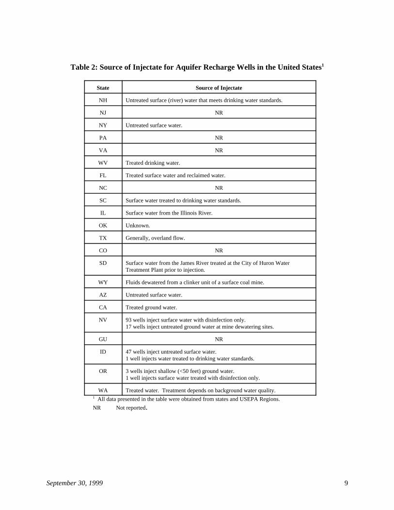
Sources of injectate in aquifer recharge wells known to exist in the United States arelisted in Table 2. As shown in this table, aquifer recharge well injectate consists of treateddrinking water, surface water (treated or untreated), surface runoff, and ground water (treated oruntreated). Treated municipal wastewater (i.e., reclaimed water) also is being used for aquiferrecharge, but wells injecting only this type of fluid are covered in the sewage treatment effluentwell summary, which is Volume 7 of the Class V UIC Study.
September 30, 1999 9
Table 2: Source of Injectate for Aquifer Recharge Wells in the United States1
State Source of Injectate
NH Untreated surface (river) water that meets drinking water standards.
NJ NR
NY Untreated surface water.
PA NR
VA NR
WV Treated drinking water.
FL Treated surface water and reclaimed water.
NC NR
SC Surface water treated to drinking water standards.
IL Surface water from the Illinois River.
OK Unknown.
TX Generally, overland flow.
CO NR
SD Surface water from the James River treated at the City of Huron WaterTreatment Plant prior to injection.
WY Fluids dewatered from a clinker unit of a surface coal mine.
AZ Untreated surface water.
CA Treated ground water.
NV 93 wells inject surface water with disinfection only.17 wells inject untreated ground water at mine dewatering sites.
GU NR
ID 47 wells inject untreated surface water.1 well injects water treated to drinking water standards.
OR 3 wells inject shallow (<50 feet) ground water.1 well injects surface water treated with disinfection only.
WA Treated water. Treatment depends on background water quality.
All data presented in the table were obtained from states and USEPA Regions.1
NR Not reported.
September 30, 1999 10
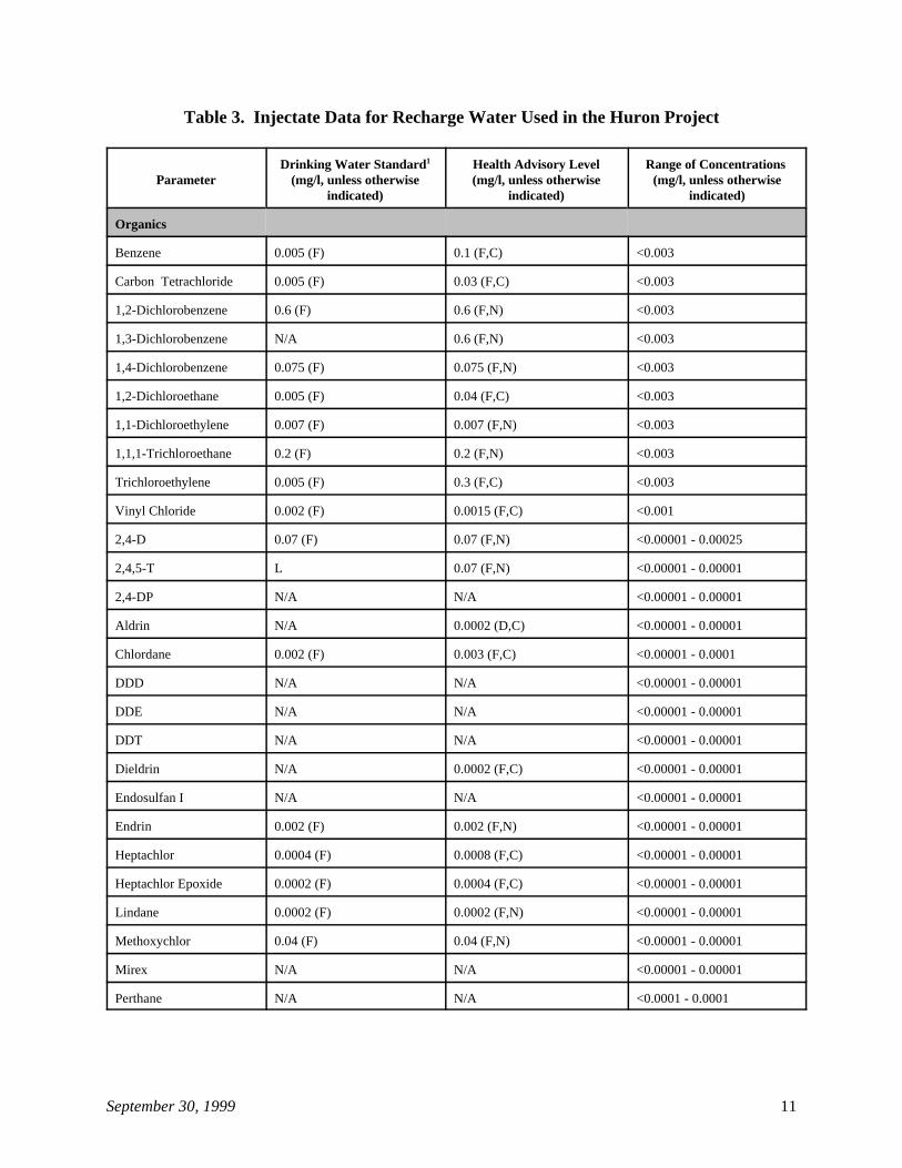
Two aquifer recharge projects in the High Plains Region of the United States provideexamples of the quality of water being injected into aquifer recharge wells. The first example isthe Huron Project in South Dakota. This aquifer recharge project uses high flows from theJames River during the spring runoff period as a source of water, treats this water in the City ofHuron’s water treatment plant, and injects the water into the Warren Aquifer. The Huron Projectis one of the projects implemented by the Bureau of Reclamation and local sponsors incooperation with USEPA and the United States Geological Survey under the "High Plains StatesGround Water Demonstration Program Act of 1983," Public Law 98-434 (the Act). The Actauthorizes and directs the Secretary of the Interior, acting through the Bureau of Reclamation, toengage in a special study of the potential for ground water recharge in the High Plains States(Colorado, Kansas, Nebraska, New Mexico, Oklahoma, South Dakota, Texas, and Wyoming)and other Reclamation Act States (Arizona, California, Idaho, Montana, Nevada, North Dakota,Oregon, Utah, and Washington) (Schaefer et al., 1994). The primary purpose of the Act is toadvance the state-of-the-art in ground water recharge techniques (U.S. Bureau of Reclamation,1996). For each demonstration program established under the Act, monitoring data have to becollected for a period of four to five years and a final report has to be submitted to Congress. Asummary report will be submitted to Congress at the conclusion of the demonstration projects,currently estimated to be early in fiscal year 2000 (U.S. Bureau of Reclamation, No date #1).
Injectate data for the Huron Project in South Dakota, along with drinking water standardsfor the purpose of comparison, are presented in Table 3. As seen in the table, all constituentsanalyzed, except fluoride, meet primary and secondary drinking water standards. For fluoride,concentrations ranging between 8 and 14 mg/l were measured. The primary drinking waterstandard for fluoride is 4 mg/l.
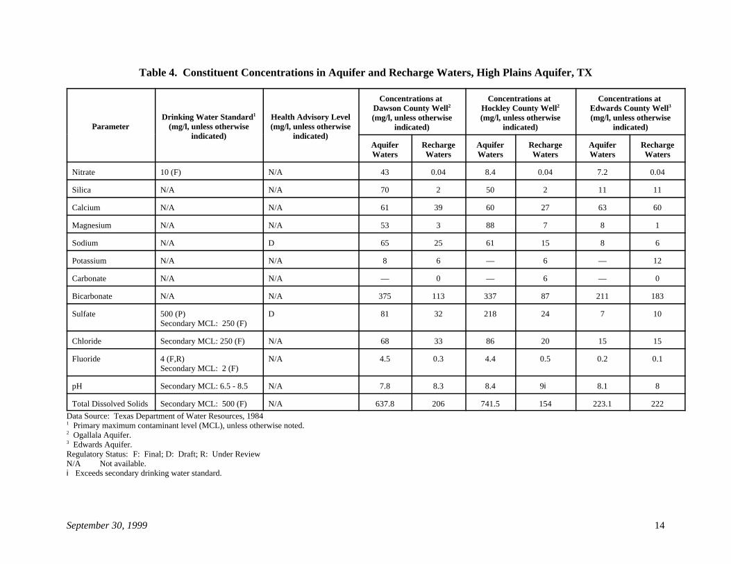
The second example is the use of aquifer recharge wells in the High Plains Region ofTexas. This type of well is used to recharge ground water aquifers when surface water is insurplus. Constituent concentrations in waters of the High Plains Aquifer and in recharge watersare presented in Table 4. Comparison of constituent concentrations in aquifer waters withcorresponding recharge waters suggest that the injected water may often be of better quality thanthat of the receiving aquifer. In addition, all constituents in the recharge waters, for whichchemical analysis data are available, meet drinking water standards. The only exception is therecharge waters of Hockley County for which the pH was 9. The secondary drinking waterstandard for pH is 6.5 to 8.5.
September 30, 1999 11
Table 3. Injectate Data for Recharge Water Used in the Huron Project
Parameter (mg/l, unless otherwise (mg/l, unless otherwise (mg/l, unless otherwiseDrinking Water Standard Health Advisory Level Range of Concentrations 1
indicated) indicated) indicated)
Organics
Benzene 0.005 (F) 0.1 (F,C) <0.003
Carbon Tetrachloride 0.005 (F) 0.03 (F,C) <0.003
1,2-Dichlorobenzene 0.6 (F) 0.6 (F,N) <0.003
1,3-Dichlorobenzene N/A 0.6 (F,N) <0.003
1,4-Dichlorobenzene 0.075 (F) 0.075 (F,N) <0.003
1,2-Dichloroethane 0.005 (F) 0.04 (F,C) <0.003
1,1-Dichloroethylene 0.007 (F) 0.007 (F,N) <0.003
1,1,1-Trichloroethane 0.2 (F) 0.2 (F,N) <0.003
Trichloroethylene 0.005 (F) 0.3 (F,C) <0.003
Vinyl Chloride 0.002 (F) 0.0015 (F,C) <0.001
2,4-D 0.07 (F) 0.07 (F,N) <0.00001 - 0.00025
2,4,5-T L 0.07 (F,N) <0.00001 - 0.00001
2,4-DP N/A N/A <0.00001 - 0.00001
Aldrin N/A 0.0002 (D,C) <0.00001 - 0.00001
Chlordane 0.002 (F) 0.003 (F,C) <0.00001 - 0.0001
DDD N/A N/A <0.00001 - 0.00001
DDE N/A N/A <0.00001 - 0.00001
DDT N/A N/A <0.00001 - 0.00001
Dieldrin N/A 0.0002 (F,C) <0.00001 - 0.00001
Endosulfan I N/A N/A <0.00001 - 0.00001
Endrin 0.002 (F) 0.002 (F,N) <0.00001 - 0.00001
Heptachlor 0.0004 (F) 0.0008 (F,C) <0.00001 - 0.00001
Heptachlor Epoxide 0.0002 (F) 0.0004 (F,C) <0.00001 - 0.00001
Lindane 0.0002 (F) 0.0002 (F,N) <0.00001 - 0.00001
Methoxychlor 0.04 (F) 0.04 (F,N) <0.00001 - 0.00001
Mirex N/A N/A <0.00001 - 0.00001
Perthane N/A N/A <0.0001 - 0.0001
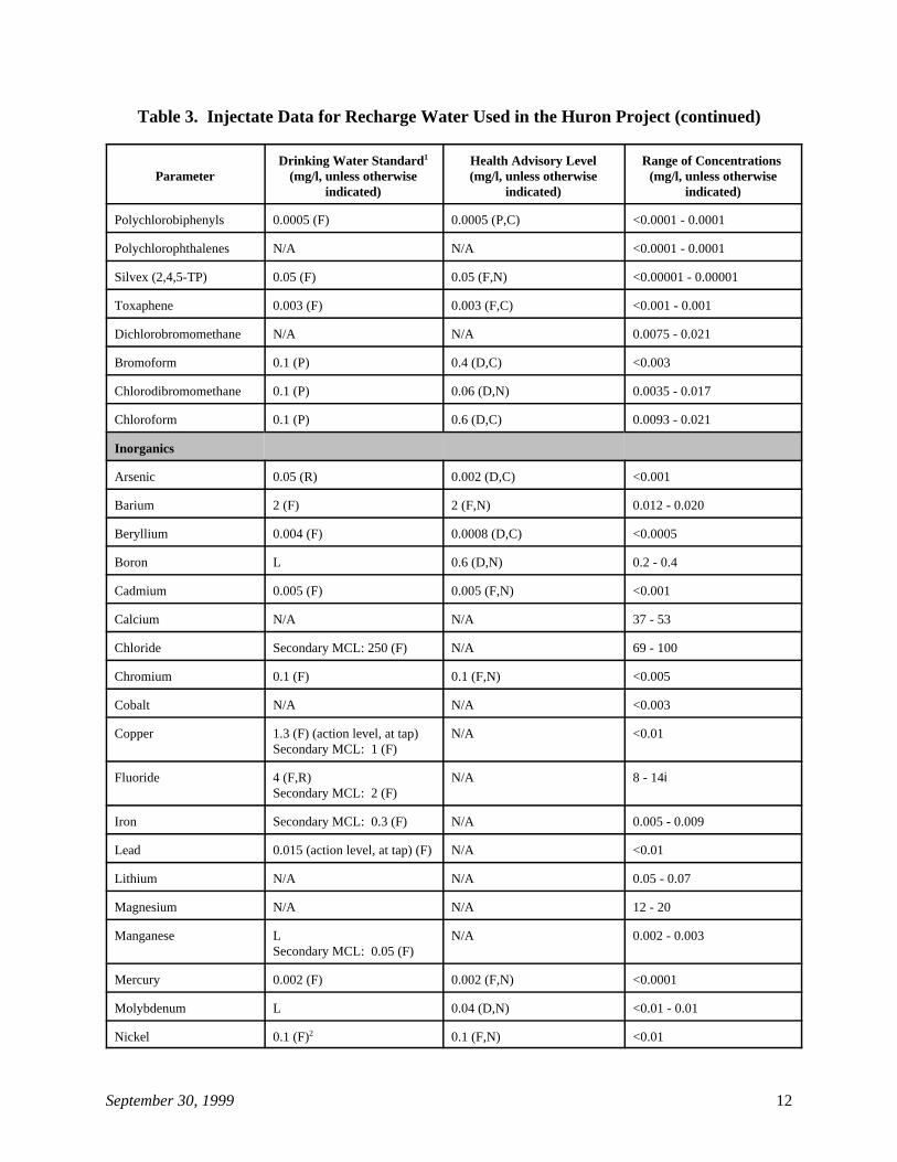
Table 3. Injectate Data for Recharge Water Used in the Huron Project (continued)
Parameter (mg/l, unless otherwise (mg/l, unless otherwise (mg/l, unless otherwiseDrinking Water Standard Health Advisory Level Range of Concentrations 1
indicated) indicated) indicated)
September 30, 1999 12
Polychlorobiphenyls 0.0005 (F) 0.0005 (P,C) <0.0001 - 0.0001
Polychlorophthalenes N/A N/A <0.0001 - 0.0001
Silvex (2,4,5-TP) 0.05 (F) 0.05 (F,N) <0.00001 - 0.00001
Toxaphene 0.003 (F) 0.003 (F,C) <0.001 - 0.001
Dichlorobromomethane N/A N/A 0.0075 - 0.021
Bromoform 0.1 (P) 0.4 (D,C) <0.003
Chlorodibromomethane 0.1 (P) 0.06 (D,N) 0.0035 - 0.017
Chloroform 0.1 (P) 0.6 (D,C) 0.0093 - 0.021
Inorganics
Arsenic 0.05 (R) 0.002 (D,C) <0.001
Barium 2 (F) 2 (F,N) 0.012 - 0.020
Beryllium 0.004 (F) 0.0008 (D,C) <0.0005
Boron L 0.6 (D,N) 0.2 - 0.4
Cadmium 0.005 (F) 0.005 (F,N) <0.001
Calcium N/A N/A 37 - 53
Chloride Secondary MCL: 250 (F) N/A 69 - 100
Chromium 0.1 (F) 0.1 (F,N) <0.005
Cobalt N/A N/A <0.003
Copper 1.3 (F) (action level, at tap) N/A <0.01Secondary MCL: 1 (F)
Fluoride 4 (F,R) N/A 8 - 14iSecondary MCL: 2 (F)
Iron Secondary MCL: 0.3 (F) N/A 0.005 - 0.009
Lead 0.015 (action level, at tap) (F) N/A <0.01
Lithium N/A N/A 0.05 - 0.07
Magnesium N/A N/A 12 - 20
Manganese L N/A 0.002 - 0.003Secondary MCL: 0.05 (F)
Mercury 0.002 (F) 0.002 (F,N) <0.0001
Molybdenum L 0.04 (D,N) <0.01 - 0.01
Nickel 0.1 (F) 0.1 (F,N) <0.012
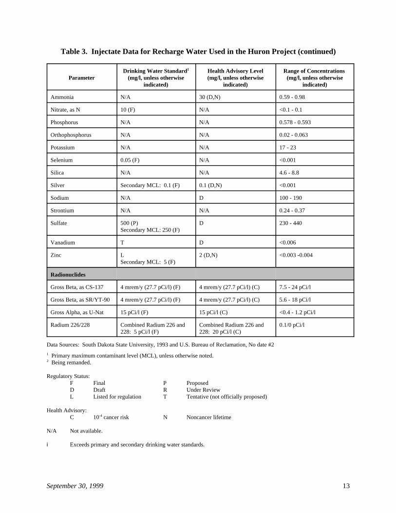
Table 3. Injectate Data for Recharge Water Used in the Huron Project (continued)
Parameter (mg/l, unless otherwise (mg/l, unless otherwise (mg/l, unless otherwiseDrinking Water Standard Health Advisory Level Range of Concentrations 1
indicated) indicated) indicated)
September 30, 1999 13
Ammonia N/A 30 (D,N) 0.59 - 0.98
Nitrate, as N 10 (F) N/A <0.1 - 0.1
Phosphorus N/A N/A 0.578 - 0.593
Orthophosphorus N/A N/A 0.02 - 0.063
Potassium N/A N/A 17 - 23
Selenium 0.05 (F) N/A <0.001
Silica N/A N/A 4.6 - 8.8
Silver Secondary MCL: 0.1 (F) 0.1 (D,N) <0.001
Sodium N/A D 100 - 190
Strontium N/A N/A 0.24 - 0.37
Sulfate 500 (P) D 230 - 440Secondary MCL: 250 (F)
Vanadium T D <0.006
Zinc L 2 (D,N) <0.003 -0.004Secondary MCL: 5 (F)
Radionuclides
Gross Beta, as CS-137 4 mrem/y (27.7 pCi/l) (F) 4 mrem/y (27.7 pCi/l) (C) 7.5 - 24 pCi/l
Gross Beta, as SR/YT-90 4 mrem/y (27.7 pCi/l) (F) 4 mrem/y (27.7 pCi/l) (C) 5.6 - 18 pCi/l
Gross Alpha, as U-Nat 15 pCi/l (F) 15 pCi/l (C) <0.4 - 1.2 pCi/l
Radium 226/228 Combined Radium 226 and Combined Radium 226 and 0.1/0 pCi/l228: 5 pCi/l (F) 228: 20 pCi/l (C)
Data Sources: South Dakota State University, 1993 and U.S. Bureau of Reclamation, No date #2
Primary maximum contaminant level (MCL), unless otherwise noted.1
Being remanded.2
Regulatory Status:F Final P ProposedD Draft R Under ReviewL Listed for regulation T Tentative (not officially proposed)
Health Advisory:C 10 cancer risk N Noncancer lifetime-4
N/A Not available.
i Exceeds primary and secondary drinking water standards.
September 30, 1999 14
Table 4. Constituent Concentrations in Aquifer and Recharge Waters, High Plains Aquifer, TX
Parameter (mg/l, unless otherwise (mg/l, unless otherwiseDrinking Water Standard Health Advisory Level1
indicated) indicated)
Concentrations at Concentrations at Concentrations at Dawson County Well Hockley County Well Edwards County Well2
(mg/l, unless otherwise (mg/l, unless otherwise (mg/l, unless otherwiseindicated) indicated) indicated)
2 3
Aquifer Recharge Aquifer Recharge Aquifer RechargeWaters Waters Waters Waters Waters Waters
Nitrate 10 (F) N/A 43 0.04 8.4 0.04 7.2 0.04
Silica N/A N/A 70 2 50 2 11 11
Calcium N/A N/A 61 39 60 27 63 60
Magnesium N/A N/A 53 3 88 7 8 1
Sodium N/A D 65 25 61 15 8 6
Potassium N/A N/A 8 6 — 6 — 12
Carbonate N/A N/A — 0 — 6 — 0
Bicarbonate N/A N/A 375 113 337 87 211 183
Sulfate 500 (P) D 81 32 218 24 7 10Secondary MCL: 250 (F)
Chloride Secondary MCL: 250 (F) N/A 68 33 86 20 15 15
Fluoride 4 (F,R) N/A 4.5 0.3 4.4 0.5 0.2 0.1Secondary MCL: 2 (F)
pH Secondary MCL: 6.5 - 8.5 N/A 7.8 8.3 8.4 9i 8.1 8
Total Dissolved Solids Secondary MCL: 500 (F) N/A 637.8 206 741.5 154 223.1 222
Data Source: Texas Department of Water Resources, 1984 Primary maximum contaminant level (MCL), unless otherwise noted.1
Ogallala Aquifer.2
Edwards Aquifer.3
Regulatory Status: F: Final; D: Draft; R: Under ReviewN/A Not available.i Exceeds secondary drinking water standard.
September 30, 1999 15
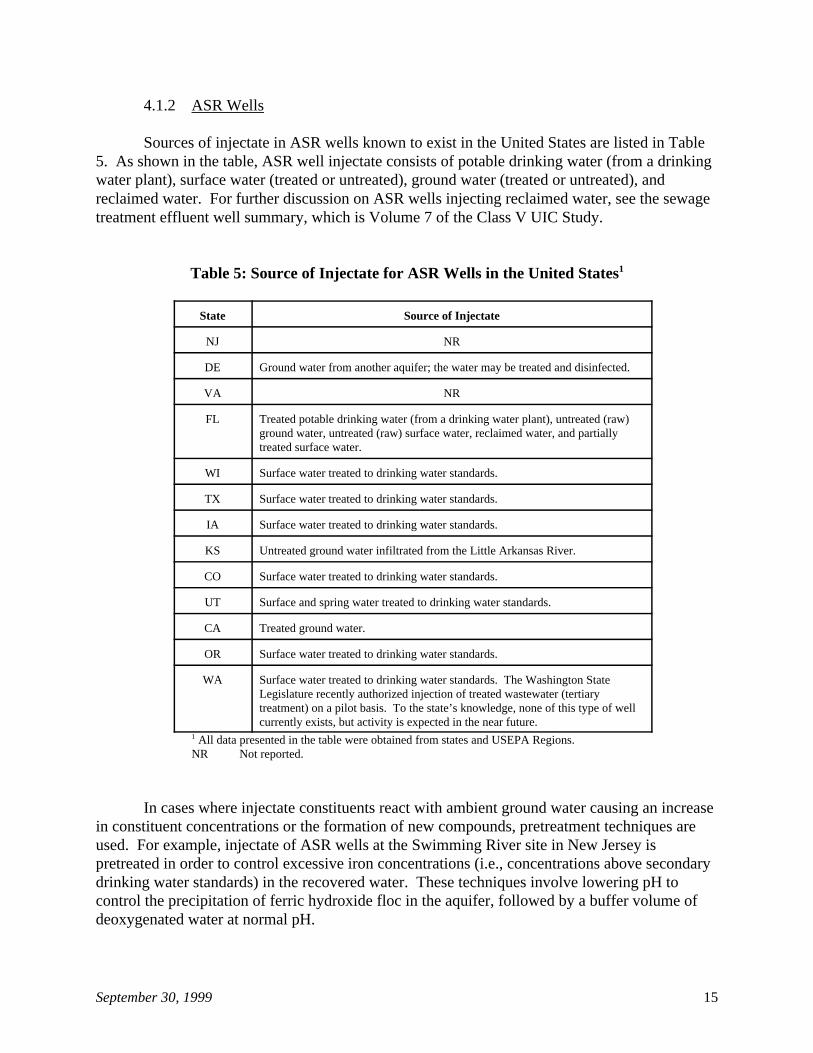
4.1.2 ASR Wells
Sources of injectate in ASR wells known to exist in the United States are listed in Table5. As shown in the table, ASR well injectate consists of potable drinking water (from a drinkingwater plant), surface water (treated or untreated), ground water (treated or untreated), andreclaimed water. For further discussion on ASR wells injecting reclaimed water, see the sewagetreatment effluent well summary, which is Volume 7 of the Class V UIC Study.
Table 5: Source of Injectate for ASR Wells in the United States1
State Source of Injectate
NJ NR
DE Ground water from another aquifer; the water may be treated and disinfected.
VA NR
FL Treated potable drinking water (from a drinking water plant), untreated (raw)ground water, untreated (raw) surface water, reclaimed water, and partiallytreated surface water.
WI Surface water treated to drinking water standards.
TX Surface water treated to drinking water standards.
IA Surface water treated to drinking water standards.
KS Untreated ground water infiltrated from the Little Arkansas River.
CO Surface water treated to drinking water standards.
UT Surface and spring water treated to drinking water standards.
CA Treated ground water.
OR Surface water treated to drinking water standards.
WA Surface water treated to drinking water standards. The Washington StateLegislature recently authorized injection of treated wastewater (tertiarytreatment) on a pilot basis. To the state’s knowledge, none of this type of wellcurrently exists, but activity is expected in the near future.
All data presented in the table were obtained from states and USEPA Regions.1
NR Not reported.
In cases where injectate constituents react with ambient ground water causing an increasein constituent concentrations or the formation of new compounds, pretreatment techniques areused. For example, injectate of ASR wells at the Swimming River site in New Jersey ispretreated in order to control excessive iron concentrations (i.e., concentrations above secondarydrinking water standards) in the recovered water. These techniques involve lowering pH tocontrol the precipitation of ferric hydroxide floc in the aquifer, followed by a buffer volume ofdeoxygenated water at normal pH.
September 30, 1999 16
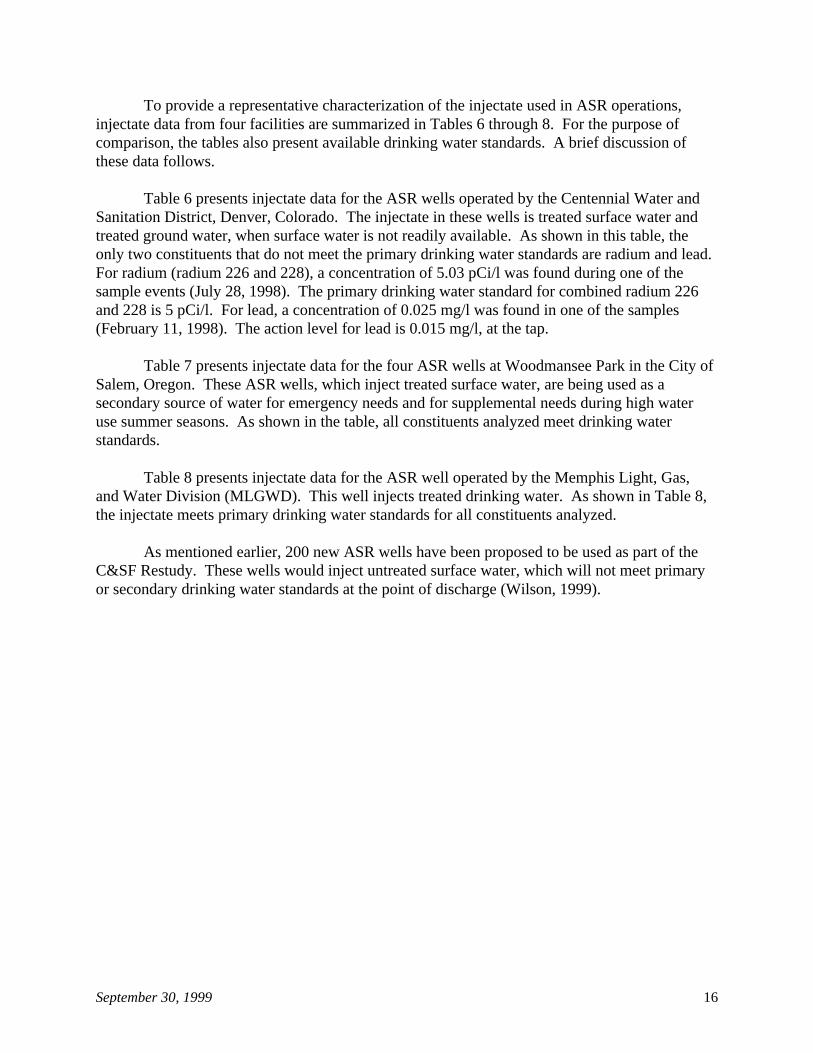
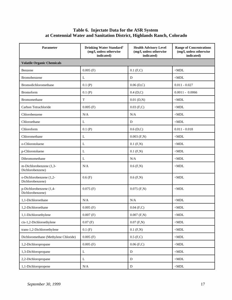
To provide a representative characterization of the injectate used in ASR operations,injectate data from four facilities are summarized in Tables 6 through 8. For the purpose ofcomparison, the tables also present available drinking water standards. A brief discussion ofthese data follows.
Table 6 presents injectate data for the ASR wells operated by the Centennial Water andSanitation District, Denver, Colorado. The injectate in these wells is treated surface water andtreated ground water, when surface water is not readily available. As shown in this table, theonly two constituents that do not meet the primary drinking water standards are radium and lead. For radium (radium 226 and 228), a concentration of 5.03 pCi/l was found during one of thesample events (July 28, 1998). The primary drinking water standard for combined radium 226and 228 is 5 pCi/l. For lead, a concentration of 0.025 mg/l was found in one of the samples(February 11, 1998). The action level for lead is 0.015 mg/l, at the tap.
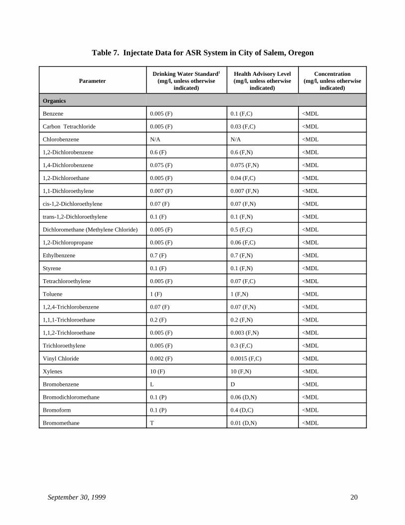
Table 7 presents injectate data for the four ASR wells at Woodmansee Park in the City ofSalem, Oregon. These ASR wells, which inject treated surface water, are being used as asecondary source of water for emergency needs and for supplemental needs during high wateruse summer seasons. As shown in the table, all constituents analyzed meet drinking waterstandards.
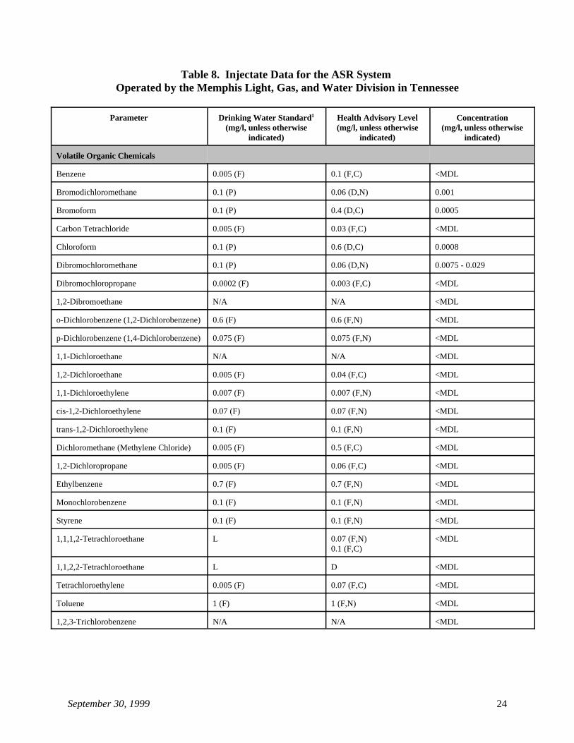
Table 8 presents injectate data for the ASR well operated by the Memphis Light, Gas,and Water Division (MLGWD). This well injects treated drinking water. As shown in Table 8,the injectate meets primary drinking water standards for all constituents analyzed.
As mentioned earlier, 200 new ASR wells have been proposed to be used as part of theC&SF Restudy. These wells would inject untreated surface water, which will not meet primaryor secondary drinking water standards at the point of discharge (Wilson, 1999).
September 30, 1999 17
Table 6. Injectate Data for the ASR System at Centennial Water and Sanitation District, Highlands Ranch, Colorado
Parameter Drinking Water Standard Health Advisory Level Range of Concentrations 1
(mg/l, unless otherwise (mg/l, unless otherwise (mg/l, unless otherwiseindicated) indicated) indicated)
Volatile Organic Chemicals
Benzene 0.005 (F) 0.1 (F,C) <MDL
Bromobenzene L D <MDL
Bromodichloromethane 0.1 (P) 0.06 (D,C) 0.011 - 0.027
Bromoform 0.1 (P) 0.4 (D,C) 0.0011 - 0.0066
Bromomethane T 0.01 (D,N) <MDL
Carbon Tetrachloride 0.005 (F) 0.03 (F,C) <MDL
Chlorobenzene N/A N/A <MDL
Chloroethane L D <MDL
Chloroform 0.1 (P) 0.6 (D,C) 0.011 - 0.018
Chloromethane L 0.003 (F,N) <MDL
o-Chlorotoluene L 0.1 (F,N) <MDL
p-Chlorotoluene L 0.1 (F,N) <MDL
Dibromomethane L N/A <MDL
m-Dichlorobenzene (1,3- N/A 0.6 (F,N) <MDLDichlorobenzene)
o-Dichlorobenzene (1,2- 0.6 (F) 0.6 (F,N) <MDLDichlorobenzene)
p-Dichlorobenzene (1,4- 0.075 (F) 0.075 (F,N) <MDLDichlorobenzene)
1,1-Dichloroethane N/A N/A <MDL
1,2-Dichloroethane 0.005 (F) 0.04 (F,C) <MDL
1,1-Dichloroethylene 0.007 (F) 0.007 (F,N) <MDL
cis-1,2-Dichloroethylene 0.07 (F) 0.07 (F,N) <MDL
trans-1,2-Dichloroethylene 0.1 (F) 0.1 (F,N) <MDL
Dichloromethane (Methylene Chloride) 0.005 (F) 0.5 (F,C) <MDL
1,2-Dichloropropane 0.005 (F) 0.06 (F,C) <MDL
1,3-Dichloropropane L D <MDL
2,2-Dichloropropane L D <MDL
1,1-Dichloropropene N/A D <MDL
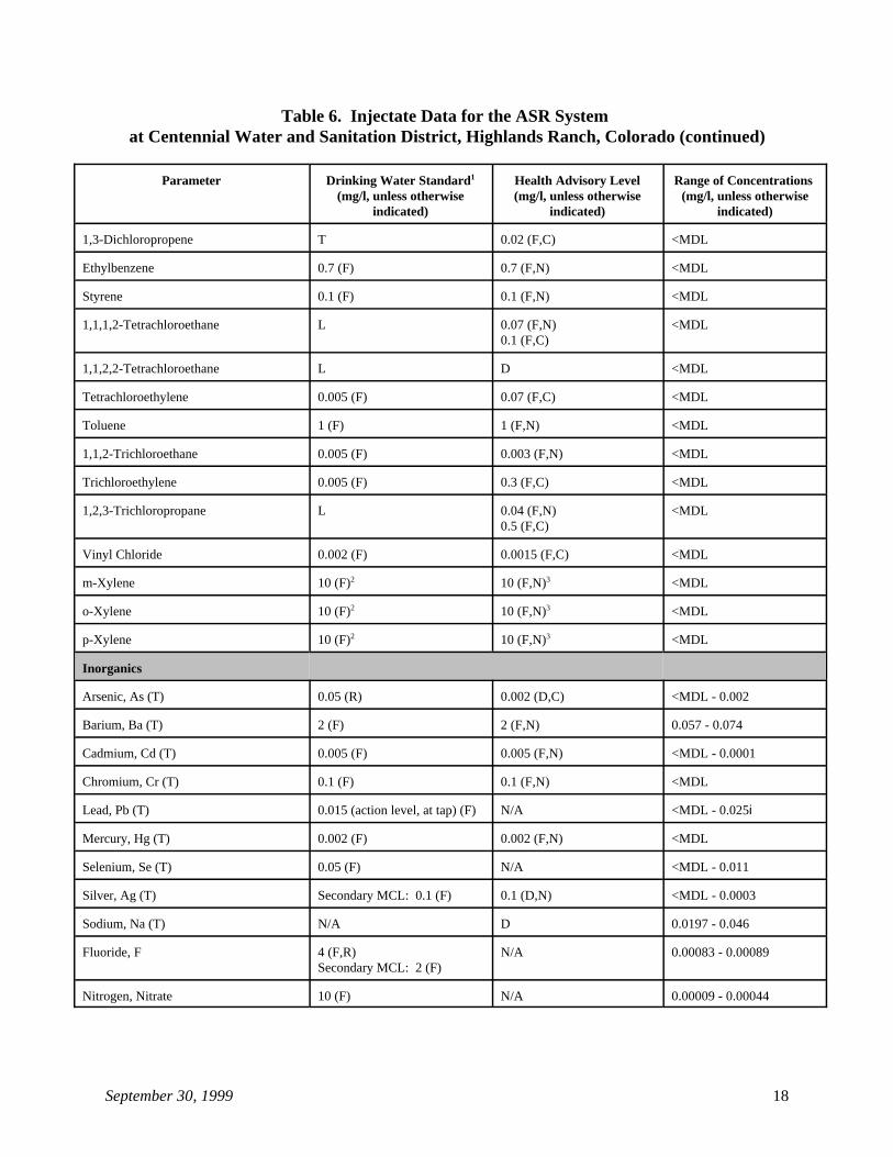
Table 6. Injectate Data for the ASR System at Centennial Water and Sanitation District, Highlands Ranch, Colorado (continued)
Parameter Drinking Water Standard Health Advisory Level Range of Concentrations 1
(mg/l, unless otherwise (mg/l, unless otherwise (mg/l, unless otherwiseindicated) indicated) indicated)
September 30, 1999 18
1,3-Dichloropropene T 0.02 (F,C) <MDL
Ethylbenzene 0.7 (F) 0.7 (F,N) <MDL
Styrene 0.1 (F) 0.1 (F,N) <MDL
1,1,1,2-Tetrachloroethane L 0.07 (F,N) <MDL0.1 (F,C)
1,1,2,2-Tetrachloroethane L D <MDL
Tetrachloroethylene 0.005 (F) 0.07 (F,C) <MDL
Toluene 1 (F) 1 (F,N) <MDL
1,1,2-Trichloroethane 0.005 (F) 0.003 (F,N) <MDL
Trichloroethylene 0.005 (F) 0.3 (F,C) <MDL
1,2,3-Trichloropropane L 0.04 (F,N) <MDL0.5 (F,C)
Vinyl Chloride 0.002 (F) 0.0015 (F,C) <MDL
m-Xylene 10 (F) 10 (F,N) <MDL2 3
o-Xylene 10 (F) 10 (F,N) <MDL2 3
p-Xylene 10 (F) 10 (F,N) <MDL2 3
Inorganics
Arsenic, As (T) 0.05 (R) 0.002 (D,C) <MDL - 0.002
Barium, Ba (T) 2 (F) 2 (F,N) 0.057 - 0.074
Cadmium, Cd (T) 0.005 (F) 0.005 (F,N) <MDL - 0.0001
Chromium, Cr (T) 0.1 (F) 0.1 (F,N) <MDL
Lead, Pb (T) 0.015 (action level, at tap) (F) N/A <MDL - 0.025i
Mercury, Hg (T) 0.002 (F) 0.002 (F,N) <MDL
Selenium, Se (T) 0.05 (F) N/A <MDL - 0.011
Silver, Ag (T) Secondary MCL: 0.1 (F) 0.1 (D,N) <MDL - 0.0003
Sodium, Na (T) N/A D 0.0197 - 0.046
Fluoride, F 4 (F,R) N/A 0.00083 - 0.00089Secondary MCL: 2 (F)
Nitrogen, Nitrate 10 (F) N/A 0.00009 - 0.00044
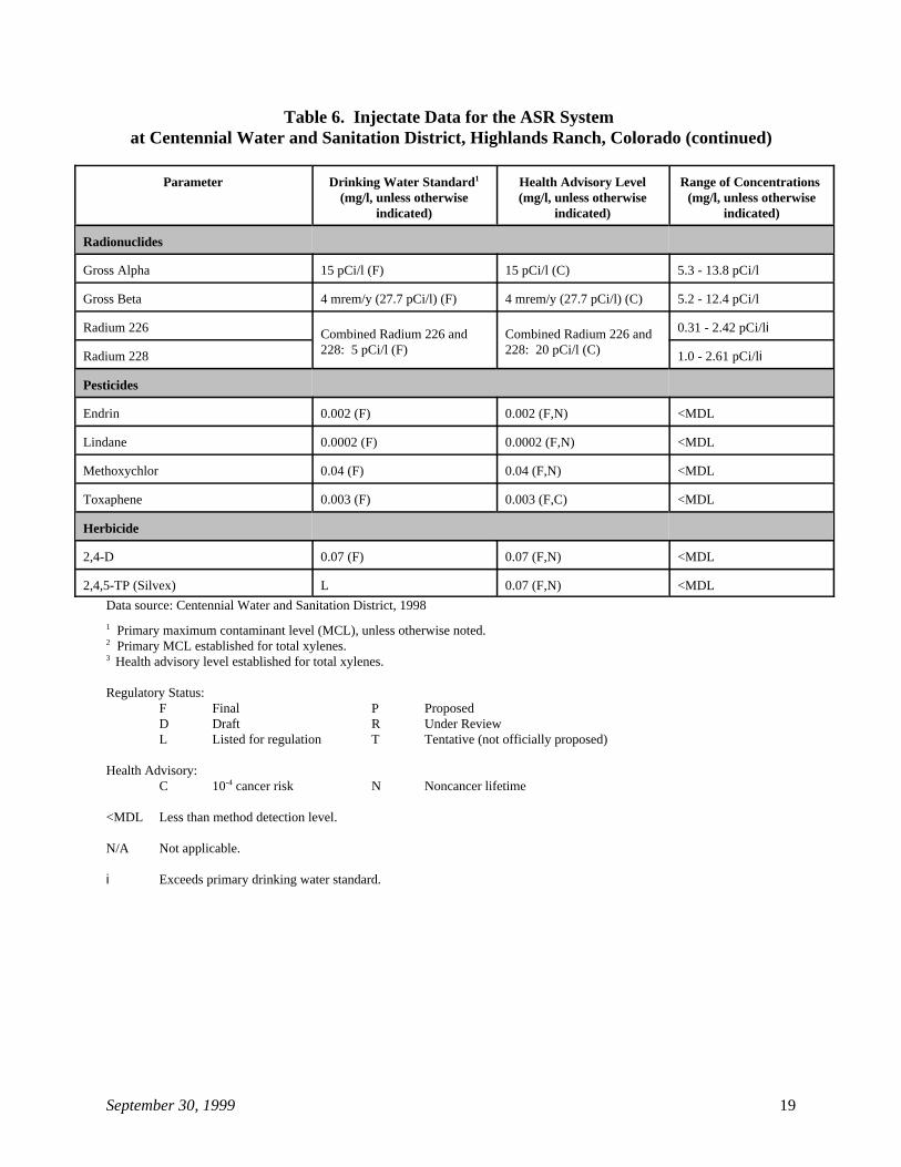
Table 6. Injectate Data for the ASR System at Centennial Water and Sanitation District, Highlands Ranch, Colorado (continued)
Parameter Drinking Water Standard Health Advisory Level Range of Concentrations 1
(mg/l, unless otherwise (mg/l, unless otherwise (mg/l, unless otherwiseindicated) indicated) indicated)
September 30, 1999 19
Radionuclides
Gross Alpha 15 pCi/l (F) 15 pCi/l (C) 5.3 - 13.8 pCi/l
Gross Beta 4 mrem/y (27.7 pCi/l) (F) 4 mrem/y (27.7 pCi/l) (C) 5.2 - 12.4 pCi/l
Radium 226 0.31 - 2.42 pCi/liCombined Radium 226 and Combined Radium 226 and228: 5 pCi/l (F) 228: 20 pCi/l (C)Radium 228 1.0 - 2.61 pCi/li
Pesticides
Endrin 0.002 (F) 0.002 (F,N) <MDL
Lindane 0.0002 (F) 0.0002 (F,N) <MDL
Methoxychlor 0.04 (F) 0.04 (F,N) <MDL
Toxaphene 0.003 (F) 0.003 (F,C) <MDL
Herbicide
2,4-D 0.07 (F) 0.07 (F,N) <MDL
2,4,5-TP (Silvex) L 0.07 (F,N) <MDL
Data source: Centennial Water and Sanitation District, 1998
Primary maximum contaminant level (MCL), unless otherwise noted.1
Primary MCL established for total xylenes.2
Health advisory level established for total xylenes.3
Regulatory Status:F Final P ProposedD Draft R Under ReviewL Listed for regulation T Tentative (not officially proposed)
Health Advisory:C 10 cancer risk N Noncancer lifetime-4
<MDL Less than method detection level.
N/A Not applicable.
i Exceeds primary drinking water standard.
September 30, 1999 20
Table 7. Injectate Data for ASR System in City of Salem, Oregon
Parameter (mg/l, unless otherwise (mg/l, unless otherwise (mg/l, unless otherwiseDrinking Water Standard Health Advisory Level Concentration1
indicated) indicated) indicated)
Organics
Benzene 0.005 (F) 0.1 (F,C) <MDL
Carbon Tetrachloride 0.005 (F) 0.03 (F,C) <MDL
Chlorobenzene N/A N/A <MDL
1,2-Dichlorobenzene 0.6 (F) 0.6 (F,N) <MDL
1,4-Dichlorobenzene 0.075 (F) 0.075 (F,N) <MDL
1,2-Dichloroethane 0.005 (F) 0.04 (F,C) <MDL
1,1-Dichloroethylene 0.007 (F) 0.007 (F,N) <MDL
cis-1,2-Dichloroethylene 0.07 (F) 0.07 (F,N) <MDL
trans-1,2-Dichloroethylene 0.1 (F) 0.1 (F,N) <MDL
Dichloromethane (Methylene Chloride) 0.005 (F) 0.5 (F,C) <MDL
1,2-Dichloropropane 0.005 (F) 0.06 (F,C) <MDL
Ethylbenzene 0.7 (F) 0.7 (F,N) <MDL
Styrene 0.1 (F) 0.1 (F,N) <MDL
Tetrachloroethylene 0.005 (F) 0.07 (F,C) <MDL
Toluene 1 (F) 1 (F,N) <MDL
1,2,4-Trichlorobenzene 0.07 (F) 0.07 (F,N) <MDL
1,1,1-Trichloroethane 0.2 (F) 0.2 (F,N) <MDL
1,1,2-Trichloroethane 0.005 (F) 0.003 (F,N) <MDL
Trichloroethylene 0.005 (F) 0.3 (F,C) <MDL
Vinyl Chloride 0.002 (F) 0.0015 (F,C) <MDL
Xylenes 10 (F) 10 (F,N) <MDL
Bromobenzene L D <MDL
Bromodichloromethane 0.1 (P) 0.06 (D,N) <MDL
Bromoform 0.1 (P) 0.4 (D,C) <MDL
Bromomethane T 0.01 (D,N) <MDL
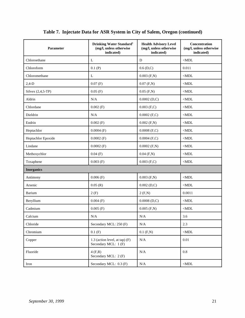
Table 7. Injectate Data for ASR System in City of Salem, Oregon (continued)
Parameter (mg/l, unless otherwise (mg/l, unless otherwise (mg/l, unless otherwiseDrinking Water Standard Health Advisory Level Concentration1
indicated) indicated) indicated)
September 30, 1999 21
Chloroethane L D <MDL
Chloroform 0.1 (P) 0.6 (D,C) 0.011
Chloromethane L 0.003 (F,N) <MDL
2,4-D 0.07 (F) 0.07 (F,N) <MDL
Silvex (2,4,5-TP) 0.05 (F) 0.05 (F,N) <MDL
Aldrin N/A 0.0002 (D,C) <MDL
Chlordane 0.002 (F) 0.003 (F,C) <MDL
Dieldrin N/A 0.0002 (F,C) <MDL
Endrin 0.002 (F) 0.002 (F,N) <MDL
Heptachlor 0.0004 (F) 0.0008 (F,C) <MDL
Heptachlor Epoxide 0.0002 (F) 0.0004 (F,C) <MDL
Lindane 0.0002 (F) 0.0002 (F,N) <MDL
Methoxychlor 0.04 (F) 0.04 (F,N) <MDL
Toxaphene 0.003 (F) 0.003 (F,C) <MDL
Inorganics
Antimony 0.006 (F) 0.003 (F,N) <MDL
Arsenic 0.05 (R) 0.002 (D,C) <MDL
Barium 2 (F) 2 (F,N) 0.0011
Beryllium 0.004 (F) 0.0008 (D,C) <MDL
Cadmium 0.005 (F) 0.005 (F,N) <MDL
Calcium N/A N/A 3.6
Chloride Secondary MCL: 250 (F) N/A 2.3
Chromium 0.1 (F) 0.1 (F,N) <MDL
Copper 1.3 (action level, at tap) (F) N/A 0.01Secondary MCL: 1 (F)
Fluoride 4 (F,R) N/A 0.8Secondary MCL: 2 (F)
Iron Secondary MCL: 0.3 (F) N/A <MDL
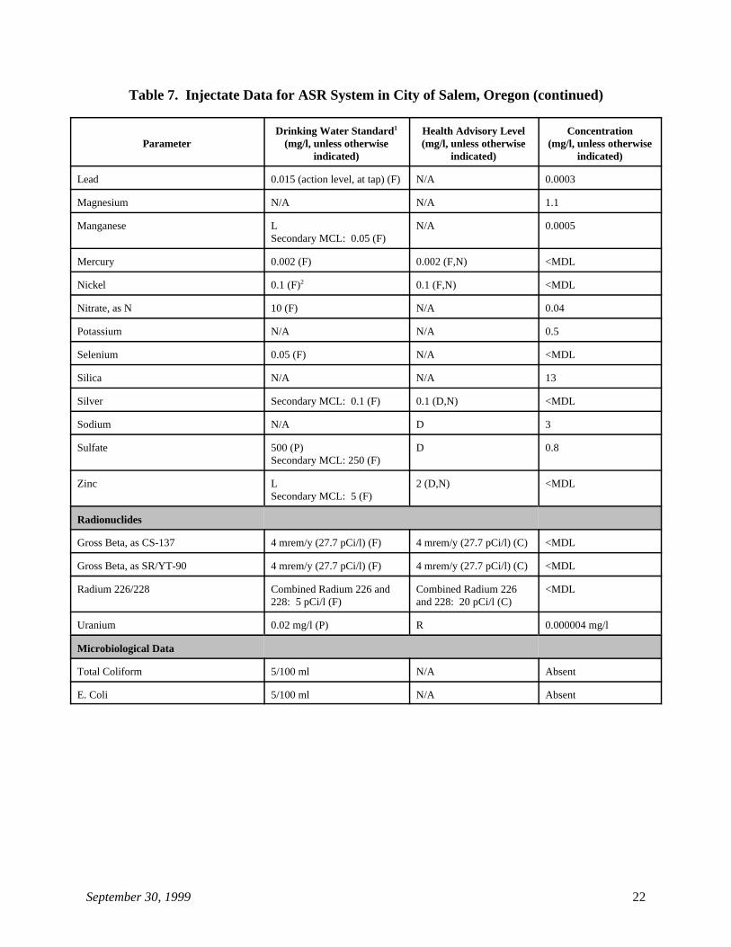
Table 7. Injectate Data for ASR System in City of Salem, Oregon (continued)
Parameter (mg/l, unless otherwise (mg/l, unless otherwise (mg/l, unless otherwiseDrinking Water Standard Health Advisory Level Concentration1
indicated) indicated) indicated)
September 30, 1999 22
Lead 0.015 (action level, at tap) (F) N/A 0.0003
Magnesium N/A N/A 1.1
Manganese L N/A 0.0005Secondary MCL: 0.05 (F)
Mercury 0.002 (F) 0.002 (F,N) <MDL
Nickel 0.1 (F) 0.1 (F,N) <MDL2
Nitrate, as N 10 (F) N/A 0.04
Potassium N/A N/A 0.5
Selenium 0.05 (F) N/A <MDL
Silica N/A N/A 13
Silver Secondary MCL: 0.1 (F) 0.1 (D,N) <MDL
Sodium N/A D 3
Sulfate 500 (P) D 0.8Secondary MCL: 250 (F)
Zinc L 2 (D,N) <MDLSecondary MCL: 5 (F)
Radionuclides
Gross Beta, as CS-137 4 mrem/y (27.7 pCi/l) (F) 4 mrem/y (27.7 pCi/l) (C) <MDL
Gross Beta, as SR/YT-90 4 mrem/y (27.7 pCi/l) (F) 4 mrem/y (27.7 pCi/l) (C) <MDL
Radium 226/228 Combined Radium 226 and Combined Radium 226 <MDL228: 5 pCi/l (F) and 228: 20 pCi/l (C)
Uranium 0.02 mg/l (P) R 0.000004 mg/l
Microbiological Data
Total Coliform 5/100 ml N/A Absent
E. Coli 5/100 ml N/A Absent
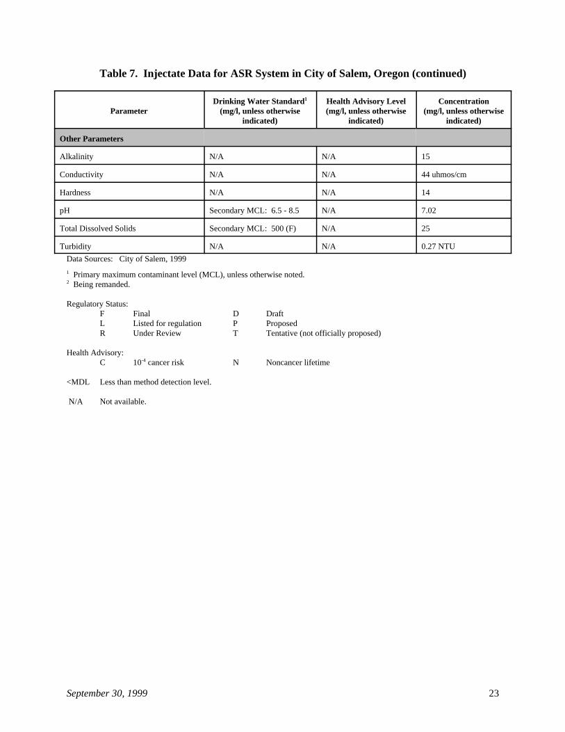
Table 7. Injectate Data for ASR System in City of Salem, Oregon (continued)
Parameter (mg/l, unless otherwise (mg/l, unless otherwise (mg/l, unless otherwiseDrinking Water Standard Health Advisory Level Concentration1
indicated) indicated) indicated)
September 30, 1999 23
Other Parameters
Alkalinity N/A N/A 15
Conductivity N/A N/A 44 uhmos/cm
Hardness N/A N/A 14
pH Secondary MCL: 6.5 - 8.5 N/A 7.02
Total Dissolved Solids Secondary MCL: 500 (F) N/A 25
Turbidity N/A N/A 0.27 NTU
Data Sources: City of Salem, 1999
Primary maximum contaminant level (MCL), unless otherwise noted.1
Being remanded.2
Regulatory Status:F Final D DraftL Listed for regulation P ProposedR Under Review T Tentative (not officially proposed)
Health Advisory:C 10 cancer risk N Noncancer lifetime-4
<MDL Less than method detection level.
N/A Not available.
September 30, 1999 24
Table 8. Injectate Data for the ASR System Operated by the Memphis Light, Gas, and Water Division in Tennessee
Parameter Drinking Water Standard Health Advisory Level Concentration1
(mg/l, unless otherwise (mg/l, unless otherwise (mg/l, unless otherwiseindicated) indicated) indicated)
Volatile Organic Chemicals
Benzene 0.005 (F) 0.1 (F,C) <MDL
Bromodichloromethane 0.1 (P) 0.06 (D,N) 0.001
Bromoform 0.1 (P) 0.4 (D,C) 0.0005
Carbon Tetrachloride 0.005 (F) 0.03 (F,C) <MDL
Chloroform 0.1 (P) 0.6 (D,C) 0.0008
Dibromochloromethane 0.1 (P) 0.06 (D,N) 0.0075 - 0.029
Dibromochloropropane 0.0002 (F) 0.003 (F,C) <MDL
1,2-Dibromoethane N/A N/A <MDL
o-Dichlorobenzene (1,2-Dichlorobenzene) 0.6 (F) 0.6 (F,N) <MDL
p-Dichlorobenzene (1,4-Dichlorobenzene) 0.075 (F) 0.075 (F,N) <MDL
1,1-Dichloroethane N/A N/A <MDL
1,2-Dichloroethane 0.005 (F) 0.04 (F,C) <MDL
1,1-Dichloroethylene 0.007 (F) 0.007 (F,N) <MDL
cis-1,2-Dichloroethylene 0.07 (F) 0.07 (F,N) <MDL
trans-1,2-Dichloroethylene 0.1 (F) 0.1 (F,N) <MDL
Dichloromethane (Methylene Chloride) 0.005 (F) 0.5 (F,C) <MDL
1,2-Dichloropropane 0.005 (F) 0.06 (F,C) <MDL
Ethylbenzene 0.7 (F) 0.7 (F,N) <MDL
Monochlorobenzene 0.1 (F) 0.1 (F,N) <MDL
Styrene 0.1 (F) 0.1 (F,N) <MDL
1,1,1,2-Tetrachloroethane L 0.07 (F,N) <MDL0.1 (F,C)
1,1,2,2-Tetrachloroethane L D <MDL
Tetrachloroethylene 0.005 (F) 0.07 (F,C) <MDL
Toluene 1 (F) 1 (F,N) <MDL
1,2,3-Trichlorobenzene N/A N/A <MDL
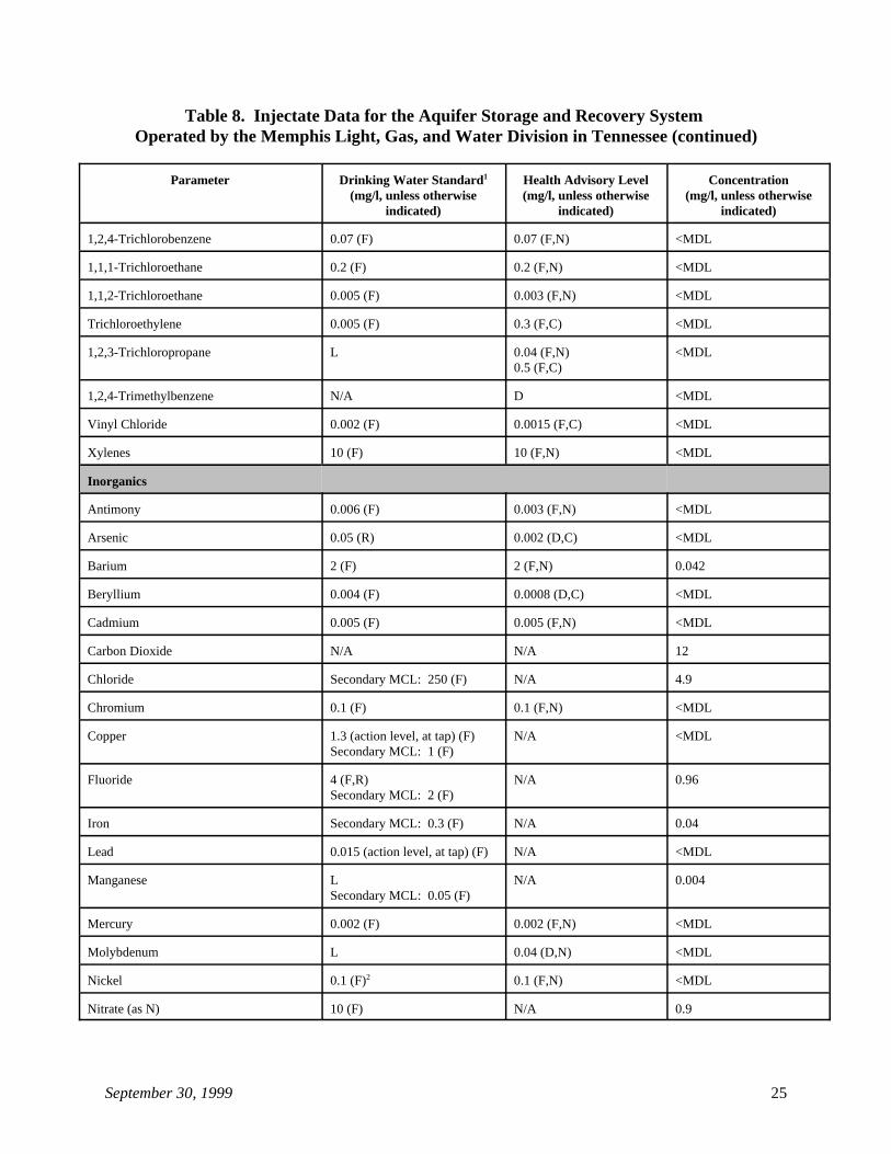
Table 8. Injectate Data for the Aquifer Storage and Recovery System Operated by the Memphis Light, Gas, and Water Division in Tennessee (continued)
Parameter Drinking Water Standard Health Advisory Level Concentration1
(mg/l, unless otherwise (mg/l, unless otherwise (mg/l, unless otherwiseindicated) indicated) indicated)
September 30, 1999 25
1,2,4-Trichlorobenzene 0.07 (F) 0.07 (F,N) <MDL
1,1,1-Trichloroethane 0.2 (F) 0.2 (F,N) <MDL
1,1,2-Trichloroethane 0.005 (F) 0.003 (F,N) <MDL
Trichloroethylene 0.005 (F) 0.3 (F,C) <MDL
1,2,3-Trichloropropane L 0.04 (F,N) <MDL0.5 (F,C)
1,2,4-Trimethylbenzene N/A D <MDL
Vinyl Chloride 0.002 (F) 0.0015 (F,C) <MDL
Xylenes 10 (F) 10 (F,N) <MDL
Inorganics
Antimony 0.006 (F) 0.003 (F,N) <MDL
Arsenic 0.05 (R) 0.002 (D,C) <MDL
Barium 2 (F) 2 (F,N) 0.042
Beryllium 0.004 (F) 0.0008 (D,C) <MDL
Cadmium 0.005 (F) 0.005 (F,N) <MDL
Carbon Dioxide N/A N/A 12
Chloride Secondary MCL: 250 (F) N/A 4.9
Chromium 0.1 (F) 0.1 (F,N) <MDL
Copper 1.3 (action level, at tap) (F) N/A <MDLSecondary MCL: 1 (F)
Fluoride 4 (F,R) N/A 0.96Secondary MCL: 2 (F)
Iron Secondary MCL: 0.3 (F) N/A 0.04
Lead 0.015 (action level, at tap) (F) N/A <MDL
Manganese L N/A 0.004Secondary MCL: 0.05 (F)
Mercury 0.002 (F) 0.002 (F,N) <MDL
Molybdenum L 0.04 (D,N) <MDL
Nickel 0.1 (F) 0.1 (F,N) <MDL2
Nitrate (as N) 10 (F) N/A 0.9
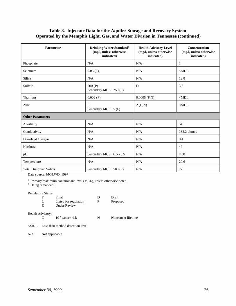
Table 8. Injectate Data for the Aquifer Storage and Recovery System Operated by the Memphis Light, Gas, and Water Division in Tennessee (continued)
Parameter Drinking Water Standard Health Advisory Level Concentration1
(mg/l, unless otherwise (mg/l, unless otherwise (mg/l, unless otherwiseindicated) indicated) indicated)
September 30, 1999 26
Phosphate N/A N/A 1
Selenium 0.05 (F) N/A <MDL
Silica N/A N/A 13.8
Sulfate 500 (P) D 3.6Secondary MCL: 250 (F)
Thallium 0.002 (F) 0.0005 (F,N) <MDL
Zinc L 2 (D,N) <MDL Secondary MCL: 5 (F)
Other Parameters
Alkalinity N/A N/A 54
Conductivity N/A N/A 133.2 uhmos
Dissolved Oxygen N/A N/A 8.4
Hardness N/A N/A 49
pH Secondary MCL: 6.5 - 8.5 N/A 7.08
Temperature N/A N/A 20.6
Total Dissolved Solids Secondary MCL: 500 (F) N/A 77
Data source: MGLWD, 1997
Primary maximum contaminant level (MCL), unless otherwise noted.1
Being remanded.2
Regulatory Status:F Final D DraftL Listed for regulation P ProposedR Under Review
Health Advisory:C 10 cancer risk N Noncancer lifetime-4
<MDL Less than method detection level.
N/A Not applicable.
September 30, 1999 27
4.2 Well Characteristics
4.2.1 Design Features
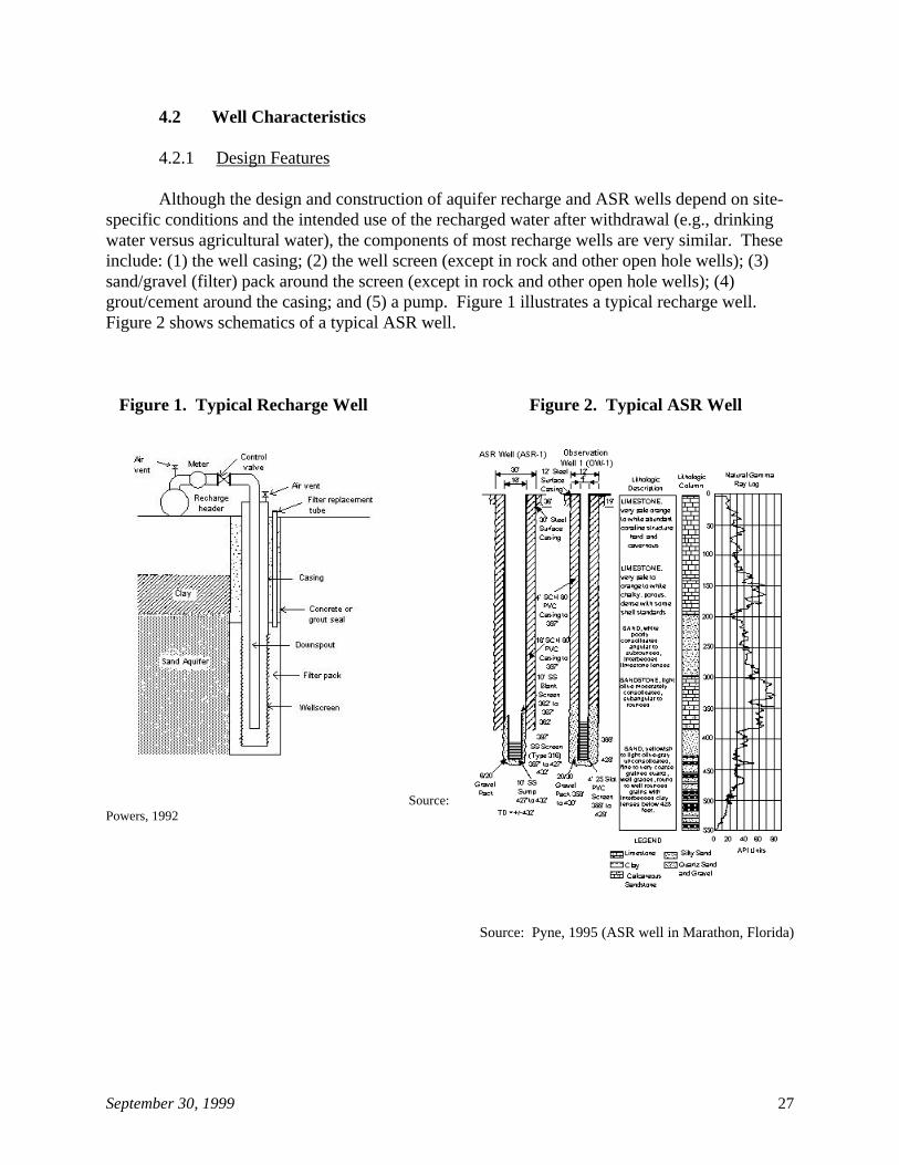
Although the design and construction of aquifer recharge and ASR wells depend on site-specific conditions and the intended use of the recharged water after withdrawal (e.g., drinkingwater versus agricultural water), the components of most recharge wells are very similar. Theseinclude: (1) the well casing; (2) the well screen (except in rock and other open hole wells); (3)sand/gravel (filter) pack around the screen (except in rock and other open hole wells); (4)grout/cement around the casing; and (5) a pump. Figure 1 illustrates a typical recharge well. Figure 2 shows schematics of a typical ASR well.
Figure 1. Typical Recharge Well Figure 2. Typical ASR Well
Source: Powers, 1992
Source: Pyne, 1995 (ASR well in Marathon, Florida)
September 30, 1999 28
Uncoated steel casing is typically used in the construction of injection wells. However,steel-cased ASR wells are more vulnerable to rusting than most other injection wells becausealternating periods of recharge and recovery during ASR operations expose a large surface areato frequent wetting and drying. This frequent wetting and drying causes rust to form on theinside of the well. During recharge periods, the rust becomes suspended in injection water withother solids and contributes to well clogging. To avoid this problem, ASR wells may beconstructed using material that will not contribute to the production of rust—in particular,polyvinyl chloride (PVC). However, if steel casing is required, epoxy coating can substantiallyreduce the surface area of steel subject to rusting. These two approaches have been proven to besuccessful in operational ASR systems. Other materials that could be used in the construction ofASR well casings are fiberglass and stainless steel, but they are more expensive alternatives. One example of the use of stainless steel in the construction of ASR wells is a well in the city ofDelray Beach, Florida. That ASR well has a type 316 stainless steel final casing to protectagainst electrolysis.
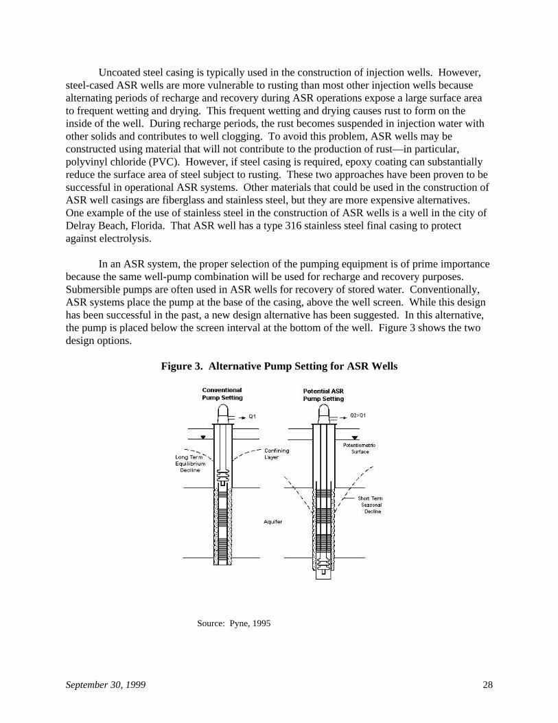
In an ASR system, the proper selection of the pumping equipment is of prime importancebecause the same well-pump combination will be used for recharge and recovery purposes. Submersible pumps are often used in ASR wells for recovery of stored water. Conventionally,ASR systems place the pump at the base of the casing, above the well screen. While this designhas been successful in the past, a new design alternative has been suggested. In this alternative,the pump is placed below the screen interval at the bottom of the well. Figure 3 shows the twodesign options.
Figure 3. Alternative Pump Setting for ASR Wells
Source: Pyne, 1995
September 30, 1999 29
It should be noted that the above description covers the most common well design. However, wells could be constructed using other designs, such as slant or horizontal casings ormultiple casings nested on a single bore hole to control injection into specific aquifer zones.
4.2.2 Siting Considerations
There are several factors that are common to the site selection process of all aquiferrecharge and ASR wells. These include physical siting criteria, recharge water availability andquality, water demand (if applicable), regulatory and institutional issues, and economicconsiderations. A discussion of each of these factors follows.
Physical Siting Criteria
Under ideal conditions a well will accept recharge water at least as readily as it will yieldwater by pumping. However, actual conditions are never ideal. For that reason, it is common toconduct a hydrogeologic evaluation of the area. This evaluation provides the informationnecessary to select suitable storage zones, recharge water sources, and treatment requirements (ifany). These hydrogeologic characteristics affect the location and design of the wells and have tobe considered for a successful recharge project.
The hydrogeologic evaluation considers the following factors:
1. availability of an aquifer suitable for recharge;2. aquifer areal extent, thickness, and depth;3. geologic structure (unconsolidated, consolidated, fractures, bedding planes,
fissures, etc.);4. hydraulic characteristics (transmissivity, storativity, hydraulic conductivity,
porosity, etc.);5. mineralogy of clays, sands, and other soil components;6. confining layers or aquitards (areal extent, thickness, and depth);7. lithology of aquifer and confining layers;8. chemical characteristics of the native ground water;9. native ground water velocity and direction;10. water table levels or potentiometric surface;11. local gradient of the potentiometric surface;12. geochemical compatibility of recharge and native water with formation minerals;13. proximity of the potential recharge site to an appropriate well field cone of
depression;14. water level differences between the aquifer and the recharge site;15. topography;16. well inventory within a reasonable radius;17. ground water withdrawals within the surrounding area;18. proximity of potential sources of contamination; and19. proximity of potential contamination plumes that may be affected by recharge
operations (O’Hare, 1986).
September 30, 1999 30
In addition, delineated wellhead protection and source water protection areas should be takeninto consideration for the siting of the wells.
In short, there are many hydrogeologic characteristics to be considered when determiningif a particular site will be suitable for artificial recharge through recharge wells. After allapplicable data are obtained, computer simulation modeling of the proposed recharge may benecessary and appropriate if there are any special concerns. Results of these analyses would beuseful in deciding the location and design of the recharge wells.
Water Availability and Quality
The availability and quality of a source of water for artificial recharge also is animportant factor in site selection. Many geographical areas that have demonstrated needs andmany sites that are physically suitable for artificial recharge can never be developed due to lackof an acceptable water source. The types of water that may be considered for artificial rechargevary with the locality.
For water to qualify for consideration as a source water for artificial recharge, thechemical, physical, and biological characteristics are evaluated relative to the native watercharacteristics. This evaluation provides the information necessary to understand the interactionbetween the recharge and the native water, establish the criteria for the quality of the rechargewater to prevent degradation in the quality of the native ground water, and determine if treatmentof the recharge water is necessary.
Water Demand
If artificial recharge is used primarily as a water resource management tool, evaluation ofwater demands, including average demands, monthly variability, and trends is important in orderto assess the duration of peak demand periods when recovery of stored water would providemaximum benefit.
Regulatory and Institutional Issues
Regulatory and institutional issues are also considered in artificial recharge site selection.These are particularly important because each state has its own requirements and procedures, asdiscussed in Section 7. In addition, the federal government (U.S. Bureau of Reclamation andU.S. Geological Survey) is involved in recharge activities through funding of localdemonstration programs and state water projects, and USEPA or state UIC Primacy Programshave a say as part of their particular Class V programs. In some instances, consideration of localperspectives and relationships is also necessary.
September 30, 1999 31
Economic Considerations
Any proposed artificial recharge project first has to be evaluated relative to itseffectiveness and economic justification. Thus, a preliminary estimate of the capital andoperating cost of injection well operations is usually developed. Such analysis considers theuseful life of the recharge project and the anticipated future availability of the recharge watersource.
4.3 Operational Practices
As stated earlier, a recharge well may be defined as a well that is used to inject water(from the surface) to replenish the water in a fresh water aquifer. When water is injected into arecharge well, a mound in the potentiometric surface of a confined aquifer, or the water table ofan unconfined aquifer, is created. The mound extends unsymmetrically in the direction of theregional flow in the aquifer. As injection continues, the areal extent of the mound spreads tooccupy an ever-increasing area (Freeze and Cherry, 1979). This process forms a cone ofrecharge that is similar in shape but the reverse of a cone of depression surrounding a pumpingwell. Thus, this process may be viewed as the inverse of the effect of a pumping well in aconfined aquifer, and, in fact, is described mathematically by the same equations, modified forthe effect of injection rather than pumping (Warner, 1965). Additional information on this topicmight be found in sources such as Driscoll (1986), O'Hare et al. (1986), and Todd (1980).
A number of factors affect recharge performance. Most of the problems in rechargingthrough wells, especially in aquifers composed of fine-grained material, involve excessivebuildup of water levels in the recharge well because of clogging of the well screen or aquifer.Injecting high-quality water reduces the frequency of well clogging, increases the operating lifeof the well, and reduces cleaning costs. In addition, chlorination of the injected water helps toprotect the well casing, prevents potential leaks, and reduces nearfield biofouling of theformations (Bloetscher, 1999). However, even when using high-quality water, clogging isinevitable.
When there is clogging and the injection head has increased above acceptable levels(approximately every three years when using high-quality injectate water), redevelopment of theinjection wells is necessary (Bruington, 1968). Redevelopment of a well involves the removal offiner material from the natural formations surrounding the perforated sections of the casing. Periodic redevelopment of the well is used to restore its efficiency and specific capacity. Thorough initial development of the injection wells will delay the need for redevelopment andincrease the initial specific capacity of the well, making it more efficient (Bruington, 1968).
Calibration of flow meters and other equipment associated with the recharge well systemis another standard operating procedure. Calibration is important to accurately keep track offlow rates in order to determine whether clogging is occurring and whether redevelopment isnecessary.
A key factor in the operation of an ASR well is its recovery efficiency. Recoveryefficiency is defined as the percentage of the water volume stored that is subsequently recovered
September 30, 1999 32
while meeting a target water quality criterion in the recovered water (Pyne, 1995). According toPyne (1995), recovery efficiency tends to improve with successive cycles when the same volumeof water is stored in each cycle because the residual water not recovered in one cycle becomes atransition or buffer zone of marginal quality surrounding the stored water in the next cycle. Building the buffer zone around each ASR well is usually completed over a series of cycles,typically about three to six, at the end of which the ultimate recovery efficiency for the site isachieved.
One ASR cycle consists of three different operating phases: injection, storage, andsubsequent recovery of potable water. During the first phase, water is injected into an aquiferwhen excess runoff or excess water supplies from a treatment plant are available for storage. During the second operating phase, potable water is stored in an aquifer. Storage times aretypically diurnal, long-term (injected during wet years then recovered in dry years), or seasonal(injected during the fall and winter then recovered in the spring and summer). Water may alsobe stored for emergency use during drought or flooding. The last part of the cycle is recovery. Recovered water is used for drinking water, irrigation, and other agricultural purposes.
5. POTENTIAL AND DOCUMENTED DAMAGE TO USDWs
5.1 Injectate Constituent Properties
As discussed in Section 4.1, water injected into aquifers through the use of aquiferrecharge and ASR wells is typically treated to meet primary and secondary drinking waterstandards. This is done to protect the host aquifer and to help ensure that the quality of theground water to be recovered is adequate for subsequent use. In addition, treatment of theinjectate in aquifer recharge and ASR wells to drinking water standards is required by mostregulatory agencies in order to prevent degradation of ambient ground water quality (see Section7). However, not all fluids injected into aquifer recharge and ASR wells meet drinking waterstandards. Injection of fluids with chemical concentrations can be allowed as long as it is foundnot to endanger USDWs. Thus, aquifer recharge and ASR wells injecting fluids that do not meetdrinking water standards can still have an environmental benefit.
It should be noted that, even when water injected into aquifers through the use of aquiferrecharge and ASR wells has been treated, a few constituents have been measured atconcentrations slightly above drinking water standards. For example, fluoride concentrations inthe recharge water used in the Huron Project in South Dakota (see Section 4.1.1) and combinedradium 226 and 228 concentrations at Centennial Water and Sanitation District in Denver,Colorado (see Section 4.1.2) have been observed slightly above the drinking water standards.
September 30, 1999 33
5.2 Observed Impacts
The objective of aquifer recharge and ASR wells is to replenish water in an aquifer forsubsequent use. Thus, aquifer recharge and ASR wells are closely controlled to make sure theysafely augment the amount of water available from a USDW. These controls make hazardousmaterial spills or illicit discharges into aquifer recharge and ASR wells unlikely.
Based on information obtained from state and USEPA Regional offices, there are noknown contamination incidents associated with the use of aquifer recharge and ASR wells. However, changes in water quality of the aquifers have been observed. In addition, in someinstances, injection of high quality water into aquifers that contain either brackish or poor qualitywater has improved the ambient ground water quality.
6. BEST MANAGEMENT PRACTICES
6.1 Aquifer Recharge and ASR Wells
6.1.1 Recharge Water Quality
In order to ensure the use of “good” quality recharge water, monitoring of recharge waterquality should be performed on a routine basis. If the recharge water is not low in suspendedsolids, air, and microorganisms, and is not chemically compatible with natural ground water andthe aquifer material, clogging can cause a recharge operation to be infeasible (Lichtler et al.,1980).
The intended use or recharge objective needs to be considered in evaluating the quality ofthe recharge water. For example, if artificial recharge is going to be used primarily for waterstorage, it is necessary to consider changes that may take place between the time of recharge andthe time of withdrawal and use by the consumer. The following basic processes must beconsidered when evaluating water quality changes likely to occur during ground water rechargeand storage:
1. biodegradation by and growth of microorganisms;2. chemical oxidation or reduction;3. sorption and ion exchange;4. filtration;5. chemical precipitation or dilution; and6. volatization or photochemical reactions.
In addition, a contaminant source inventory in the area supplying the injectate watershould be conducted in order to prevent potential contamination of the receiving aquifer.
September 30, 1999 34
6.1.2 Water Monitoring in Recharge Projects
Monitoring of ground water is necessary to ascertain the direction and rate of movementof water and the extent of water quality changes occurring during movement of the rechargedwater through the aquifer. As a result, a monitoring plan is needed to properly assess andminimize the water quality impacts of an aquifer recharge project. A monitoring plan shouldtake into account several conditions, including:
C The nature of the hydrogeologic and hydrochemical setting;
C An analysis of the source of the recharge water;
C A determination of the constituents that may be contributed by the source; and
C An assessment of potential aquifer-plugging mechanisms (Shea-Albin, 1997).
Initially, ground water and recharge water should be monitored for all analytes for whichdrinking water standards have been promulgated and for all potential contaminants in the sourcewater contribution area. It is important to analyze for all of these contaminants during thebaseline sampling period, even if a particular aquifer may not be vulnerable to contamination. Ifcontaminants of concern are not present in baseline samples, reduction in future monitoringrequirements may be possible (Shea-Albin, 1997).
6.1.3 Physical, Biological, Chemical, and Mechanical Clogging
Understanding the interaction between the recharge and native water will preventclogging of the well, which is one of the major operational problems with recharge injectionwells. Factors that may contribute to clogging of the well include:
1. suspended sediment in the recharge water (including both organic and inorganicmatter);
2. entrained air in the recharge water;3. microbial growth in a well;4. chemical reactions between recharge water and the native ground water, the
aquifer material, or both;5. ionic reactions that result in dispersion of clay particles and swelling of colloids
in a sand-and-gravel aquifer;6. iron precipitation;7. biochemical changes in the recharge water and ground water involving iron-
reducing bacteria or sulfate-reducing organisms; and8. differences in temperature between recharge and aquifer water (Pyne 1995;
Sniegocki, 1970).
The following sections describe the most common types of clogging problems andpresents methods for the early detection and prevention of problems associated with physical,biological, chemical, and mechanical clogging problems.
September 30, 1999 35
Physical Clogging
Physical clogging problems result from suspended solids clogging the pores of thereceiving formation, well screens, and/or gravel packs. This type of clogging is more prevalentin raw water recharge systems than in treated water systems because treated water will have few,if any, suspended solids. The particles settle around the recharge well, creating a need for higherinjection pressures.
For ASR wells, backflushing, or reversing the flow of the wells for recovery operations,may alleviate physical clogging problems. The amount of time a well should be backflushed issite dependent. Some ASR wells are backflushed every day for 10 minutes to 2 hours, whileothers are backflushed every few weeks for varied durations. The waste from backflushing issometimes routed to a water treatment plant for re-treatment before disposal to a drainage field,storm drain, dry well, pit, pond, or sewer system.
Physical clogging problems can also be the result of temperature differences between theinjectate and the receiving waters. When cold injection water comes into contact with warmaquifer water, outgassing (formation of gas bubbles in the injectate) may occur. The dissolvedgases in the injection water tend to escape out of solution and clog the aquifer. Outgassing dueto temperature differentials may be prevented by studying the changes in water temperature andthe mixing characteristics of the injectate and the receiving water (Pitt and Magenheimer, 1997). Cold water also tends to have a higher viscosity than warm water, which may reduce flow rates. The probability of clogging due to temperature differentials is highly site specific. Typically,temperature differentials are more likely to occur with the first injection cycle. The coldinjectate displaces the receiving water around the borehole, and after the first injection cycle,little temperature difference is found.
Biological Clogging
Recharge wells are sometimes clogged by bacterial growth. Pre-chlorination of theinjection water may solve the problem. For raw surface water or non-potable recharge systems,adding chlorine to the injection water will reduce well clogging.
Chemical Clogging
Chemical clogging problems can be caused by precipitates, clay colloids, gas bubbles,and protective chemicals (Pitt and Magenheimer, 1997). These problems may arise fromgeochemical reactions between native ground water and the injectate (Pitt and Magenheimer,1997). For example, formation of chemical precipitates (usually calcium carbonate, calciumsulphate, iron oxides, manganese oxides, magnesium hydroxide, and silicates) may arise as aresult of reactions between native ground water and recharge water. These precipitates can clogthe well screen, the gravel pack, or the formation.
Carbonate precipitation can be controlled by lowering the pH of injection water. Ifextensive precipitation has already occurred, acidizing the well with a corrosion inhibitordissolves the precipitates and prevents further corrosion of the steel casing. Injection of liquid
September 30, 1999 36
and gaseous carbon dioxide through the packer into the well screen will also remediate clogging. In this process, the gas expands, forms carbonic acid, and then freezes in the well screen. After afew days, the particles dissolve and pH values decrease (Pitt and Magenheimer, 1997).
Thin clay layers in the storage zone may swell and plug the formations around the zone. Clay colloids (particles) may also break free, travel as suspended solids, and clog the pores of thereceiving formation. Injection waters containing high sodium concentrations may exacerbateclogging by hydrating the clay, thereby causing the clay to swell, potentially clogging the welland the aquifer. Examining the well construction report and geological data will determinewhether or not clogging problems from clay colloids or thin clay layers in the injection zone canbe expected. Remedial measures include adding chemical stabilizers to the injection water toreduce clay swelling and treating the injection water to remove sodium.
Outgassing from the injection water may also cause well clogging. In this case, ananalysis of dissolved gases in the injection water should determine the degree of gas saturation. If the concentration of dissolved gases in injection water is likely to cause a well cloggingproblem, the water can be treated with degasification through a stripping column.
Sometimes chemicals such as anti-scalants, which are added to the injectate to protectpipelines in the distribution system, precipitate and contribute to aquifer clogging. Throughchemical reactions, these chemicals dissolve, loosen, and re-suspend sediments in the pipelinesand encourage bacterial growth (Pitt and Magenheimer, 1997). Using anti-scalants that degradeduring transport from the treatment plant to the injection well (e.g., zinc pyrophosphate) willdecrease the potential for well and aquifer clogging. For example, zinc pyrophosphate will notloosen and re-suspend bacteria and other solids in the pipelines because it degrades duringtransport. Well clogging due to anti-scalant chemicals may also be averted by performing acomplete investigation of the chemicals used in the water treatment process. Assessing thepotential chemical reactions between recharge water, pipeline materials, and anti-scalantchemicals will alert recharge managers to potential well clogging problems, so that clogging maybe avoided or treated before serious problems occur.
Mechanical Clogging
For ASR wells, there are some potential problems that may be caused by mechanicalclogging. Mechanical clogging problems include air entrainment and formation particlejamming (Pitt and Magenheimer, 1997). Air entrainment, one type of air clogging, trapsatmospheric air in the ASR well and in the storage zone during the storage cycle. This mayoccur when the injection water has a lower temperature than native ground water, clogging theaquifer. Sealing the annulus at the well head typically prevents air entrainment during ASRoperations. Air entrainment can be tested by conducting a mechanical integrity test (Pyne,1995). Air entrainment is not equivalent to outgassing, although temperature differentials maycause outgassing and add to aquifer clogging problems. Other common causes of air clogginginclude loose connections in piping, the use of inadequate pumps, cavitation of the injectionpump (air in the pump), and high injection velocities. These problems may best be addressed bymaintaining airtight pipelines and connections, using centrifugal pumps, and ensuring that
September 30, 1999 37
injection velocities are kept at a level below that which causes turbulent flow. Pump cavitationshould not occur during injection (Pitt and Magenheimer, 1997).
Aquifer jamming may result from particle displacement when water flow in the ASRsystem is reversed from the injection to the recovery cycle. This problem is only encountered inloosely consolidated aquifers and when the well is gravel-packed with gravel/particles ofrelatively uniform size. When the water flow is reversed, the particles are drawn back towardthe well, and their packing is rearranged. This reduces water flow efficiency and has the sameeffect on the ASR system as particulate clogging. To remediate aquifer jamming, the wells mayneed to be redeveloped by surging and pumping methods or by acidizing. Pressure fracturing orexplosive fracturing, where the aquifer is broken apart by extreme physical or explosive force,will also dislodge the jammed aquifer but may not be permitted in every state. Maintaining lowvelocities during the recovery cycle and ensuring that the screen and gravel pack match theaquifer materials can reduce the risk of aquifer jamming (Pitt and Magenheimer, 1997).
6.2 ASR Wells
6.2.1 Location and Spacing of ASR Wells and Impact on Static Ground Water Levels
The long-term and regional effects of ASR cycles need to be considered whenconfiguring ASR systems. Therefore, developing optimal water basin management strategies isimportant (Dickenson, 1997). Background basin hydrology, including natural recharge sourcesand locations, pumping patterns, discharge areas, and the proposed storage area, should beexamined. Spilling and overdraft patterns (patterns where the water table and/or aquifer level istoo high or too low) in the proposed ASR area should be assessed so that ASR injection andrecovery operations dampen extreme fluctuations in ground water levels, rather than exacerbateexisting problems. Pyne (1995) suggests that ASR facilities be located near water treatmentplants and at least 100 feet from existing or potential sources of contamination. He also pointsout that this siting criterion is a regulatory requirement in some states.
6.2.2 Operation and Maintenance Practices for ASR Wells
In order to successfully operate an ASR system, the following operation and maintenancepractices, as described by Pyne (1995), are recommended:
C Periodic change in operating mode. This occurs typically two to four times per year asthe system changes from recharge to recovery and back again.
C Backflushing to waste during recharge. This procedure is implemented at most ASRsites in order to maintain recharge capacity by purging from the well any solids that mayhave been carried into the well during recharge. Backflushing frequency varies fromevery day to every few years, depending on site-specific conditions. Some ASR wellscurrently in operation are redeveloped seasonally by extended pumping, as part of therecovery operation, without any additional backflushing frequency.
September 30, 1999 38
C Trickle flow of chlorinated water. During periods of storage, it is advisable to maintain atrickle flow of chlorinated water into the well. This will control bacterial activity in theformation immediately adjacent to the well, thereby helping to maintain recharge-specificcapacity and bacterial clogging.
C Calibration of pressure gauges, flow meters, chart recorders, and other equipmentassociated with the ASR well system. It is important to accurately keep track of flowrates and pressure and water levels in order to determine whether clogging is occurringand backflushing is necessary.
C Monitoring. Monitoring of ground water during recharge, storage, and recovery isnecessary to ascertain the direction and rate of movement of water and the extent of waterquality changes occurring during movement of the recharged water through the aquifer.
C Annual water accounting or water balance. It is important to accurately track thevolume of water stored and recovered from an ASR well system. If the volume of waterrecovered is greater than the volume of the water stored, there might be a reduction in therecovery efficiency around the well, as well as adverse impacts on water levels insurrounding areas. In addition, ASR permits are sometimes issued providing only forseasonal storage and recovery, so that annual volume recovered cannot exceed thevolume stored in the same year (Pyne, 1995).
C Periodic review of operating and water quality data. This review is necessary in order toevaluate performance relative to expectations, and make adjustments, as appropriate. This is particularly important in the first two to five years of system operation, when thegreatest changes in water levels and water quality will tend to occur and normal rangesfor various parameters tend to be defined.
7. CURRENT REGULATORY REQUIREMENTS
Several federal, state, and local programs exist that either directly manage or regulateClass V aquifer recharge and ASR wells. On the federal level, management and regulation ofthese wells falls primarily under the UIC program authorized by the Safe Drinking Water Act(SDWA). Some states and localities have used these authorities, as well as their own authorities,to extend the controls in their areas to address concerns associated with aquifer recharge andASR wells.
7.1 Federal Programs
7.1.1 SDWA
Class V wells are regulated under the authority of Part C of SDWA. Congress enactedthe SDWA to ensure protection of the quality of drinking water in the United States, and Part Cspecifically mandates the regulation of underground injection of fluids through wells. USEPAhas promulgated a series of UIC regulations under this authority. USEPA directly implements
September 30, 1999 39
these regulations for Class V wells in 19 states or territories (Alaska, American Samoa, Arizona,California, Colorado, Hawaii, Indiana, Iowa, Kentucky, Michigan, Minnesota, Montana, NewYork, Pennsylvania, South Dakota, Tennessee, Virginia, Virgin Islands, and Washington, DC). USEPA also directly implements all Class V UIC programs on Tribal lands. In all other states,which are called Primacy States, state agencies implement the Class V UIC program, withprimary enforcement responsibility.
Aquifer recharge and ASR wells currently are not subject to any specific regulationstailored just for them, but rather are subject to the UIC regulations that exist for all Class Vwells. Under 40 CFR 144.12(a), owners or operators of all injection wells, including aquiferrecharge and ASR wells, are prohibited from engaging in any injection activity that allows themovement of fluids containing any contaminant into USDWs, “if the presence of thatcontaminant may cause a violation of any primary drinking water regulation . . . or mayotherwise adversely affect the health of persons.”
Owners or operators of Class V wells are required to submit basic inventory informationunder 40 CFR 144.26. When the owner or operator submits inventory information and isoperating the well such that a USDW is not endangered, the operation of the Class V well isauthorized by rule. Moreover, under section 144.27, USEPA may require owners or operators ofany Class V well, in USEPA-administered programs, to submit additional information deemednecessary to protect USDWs. Owners or operators who fail to submit the information requiredunder sections 144.26 and 144.27 are prohibited from using their wells.
Sections 144.12(c) and (d) prescribe mandatory and discretionary actions to be taken bythe UIC Program Director if a Class V well is not in compliance with section 144.12(a). Specifically, the Director must choose between requiring the injector to apply for an individualpermit, ordering such action as closure of the well to prevent endangerment, or taking anenforcement action. Because aquifer recharge and ASR wells (like other kinds of Class V wells)are authorized by rule, they do not have to obtain a permit unless required to do so by the UICProgram Director under 40 CFR 144.25. Authorization by rule terminates upon the effectivedate of a permit issued or upon proper closure of the well.
Separate from the UIC program, the SDWA Amendments of 1996 establish arequirement for source water assessments. USEPA published guidance describing how the statesshould carry out a source water assessment program within the state’s boundaries. The finalguidance, entitled Source Water Assessment and Programs Guidance (USEPA 816-R-97-009),was released in August 1997.
State staff must conduct source water assessments that are comprised of three steps. First, state staff must delineate the boundaries of the assessment areas in the state from whichone or more public drinking water systems receive supplies of drinking water. In delineatingthese areas, state staff must use “all reasonably available hydrogeologic information on thesources of the supply of drinking water in the state and the water flow, recharge, and dischargeand any other reliable information as the state deems necessary to adequately determine suchareas.” Second, the state staff must identify contaminants of concern, and for thosecontaminants, they must inventory significant potential sources of contamination in delineated
May 2003 is the deadline including an 18-month extension.2
September 30, 1999 40
source water protection areas. Class V wells, including aquifer recharge and ASR wells, shouldbe considered as part of this source inventory, if present in a given area. Third, the state staffmust “determine the susceptibility of the public water systems in the delineated area to suchcontaminants.” State staff should complete all of these steps by May 2003 according to the finalguidance.2
7.1.2 Other Federal Rules and Programs
As stated earlier, aquifer recharge and ASR wells are used to replenish water in anaquifer. In most cases, aquifer recharge and ASR wells inject water into USDWs. Thus, theinjectate from these wells is typically treated to drinking water standards established underSection 1412 of the SDWA. This section requires USEPA to establish National PrimaryDrinking Water Regulations for a contaminant if (1) the contaminant may have an adverse publichealth effect; (2) it is known or likely to occur in public water systems with a frequency and atlevels of public health concern; and (3) if regulation of such contaminant presents a meaningfulopportunity for health risk reduction. A brief description of these regulations follows.
Total Trihalomethane Rule
In November 1979, USEPA set an interim MCL for total trihalomethanes (TTHMs) of0.10 mg/l as an annual average (44 FR 68624). Compliance is defined on the basis of a runningaverage of quarterly averages of all samples. The value for each sample is the sum of themeasured concentrations of chloroform, bromodichloromethane, dibromochloromethane, andbromoform. The interim TTHM standard only applies to community water systems usingsurface water and/or ground water serving at least 10,000 people that add a disinfectant to thedrinking water during any part of the treatment process.
Surface Water Treatment Rule
In June 29, 1989, USEPA promulgated the final Surface Water Treatment Rule (SWTR)(54 FR 27486). Under the SWTR, USEPA set maximum contaminant level goals (MCLGs) ofzero for Giardia lamblia, viruses, and Legionella; and promulgated NPDWRs for all publicwater systems using surface water sources or ground water sources under the direct influence ofsurface water. The SWTR includes treatment technique requirements for filtered and unfilteredsystems that are intended to protect against the adverse health effects of exposure to Giardialamblia, viruses, and Legionella, as well as many other pathogenic organisms. The rule becameeffective in June 1993.
Total Coliform Rule
In June 29, 1989, USEPA also promulgated the Total Coliform Rule, which applies to allpublic water systems (54 FR 27544). This regulation sets compliance with a MCL for total
September 30, 1999 41
coliforms. If a system exceeds the MCL, it must notify the public using mandatory languagedeveloped by the USEPA.
Interim Enhanced Surface Water Treatment
On December 16, 1998, USEPA finalized the Interim Enhanced Surface Water TreatmentRule (IESWTR) (63 FR 69478). The purposes of the IESWTR are to: (1) improve control ofmicrobial pathogens, including specifically protozoan Cryptosporidium, in drinking water; and(2) address risk trade-offs with disinfection products. The IESWTR applies to public watersystems that use surface or ground water under the direct influence of surface water and serve10,000 or more people. The regulation became effective on February 16, 1999.
Stage 1 Disinfection Byproducts Rule
In December 16, 1998, USEPA finalized: (1) maximum residual disinfectant level goals(MRDLGs) for chlorine, chloramines, and chlorine dioxide; (2) MCLGs for four trihalomethanes(chloroform, bromodichloromethane, dibromochloromethane, and bromoform), two haloaceticacids (dichloroacetic acid and trichloroacetic acid), bromate, and chlorite; and (3) NPDWRs forthree disinfectants (chlorine, chloramines, and chlorine dioxide), two groups of organicdisinfection byproducts (TTHMs—a sum of chloroform, bromodichloromethane,dibromochloromethane, and bromoform—and haloacetic acids—a sum of dichloroacetic acid,trichloroacetic acid, monochloroacetic acid, and mono-and dibromoacetic acids), and twoinorganic disinfection byproducts (chlorite and bromate) (63 FR 69389). The NPDWRs consistof maximum residual disinfectant levels or MCLs or treatment techniques for these disinfectantsand their byproducts. The NPDWRs also include monitoring, reporting, and public notificationrequirements for these compounds.
The Stage 1 Disinfection Byproducts Rule applies to public water systems that arecommunity water systems and nontransient, noncommunity water systems that treat their waterwith a chemical disinfectant for either primary or residual treatment. In addition, certainrequirements for chlorine dioxide apply to transient noncommunity water systems.
Radon Rule
On July 18, 1991, USEPA proposed a MCLG, a MCL, monitoring, reporting, and publicnotification requirements for radon and a number of other radionuclides in public water supplies(systems serving 25 or more individuals or with 15 or more connections) (56 FR 33050). USEPA proposed to regulate radon at 300 pCi/l.
On August 6, 1996, Congress passed amendments to the SDWA. Section 1412(b)(13)(A)of the SDWA, as amended, directs USEPA to withdraw the proposed national primary drinkingwater regulation for radon. Thus, as directed by Congress, on August 6, 1997 (62 FR 42221),USEPA withdrew the 1991 proposed MCLG, MCL, monitoring, reporting, and publicnotification requirements for radon.
USEPA expects to publish a final MCLG and national primary drinking water regulationfor radon by August, 2000.
September 30, 1999 42
Ground Water Rule
Currently, USEPA is developing a Ground Water Rule that will specify appropriate useof disinfection and encourage the use of alternative approaches, including best managementpractices and control of contamination at its source. The rule will be designed to protect againstpathogenic bacteria and viruses in source water, against growth of opportunistic pathogenicbacteria in ground water distribution systems, and to mitigate against any failure in theengineered systems, such as cross-connections or sewage infiltration into distribution systems.The Ground Water Rule will apply to systems using only ground water, which are not regulatedunder the 1989 SWTR.
USEPA expects to publish the Final Ground Water Rule by November 2000. Thestatutory deadline, under the SDWA (Section 1412(b)(8)), for the Ground Water Rule is May2002.
7.2 State and Local Programs
The requirements pertaining to aquifer recharge and ASR wells in states that containsubstantial numbers of such wells are sometimes identical. In California, for example, bothtypes of wells are regulated under the state’s Water Quality Control Act. Florida, in contrast, hasenacted specific regulatory requirements for aquifer storage and recovery. Some relatively aridwestern states have enacted rules pertaining to aquifer storage and recovery as part of theirsystem of regulating the use of the water resources of the state, but those requirements also maytouch upon well construction standards and/or monitoring requirements.
This section summarizes the existing UIC programs in the states where the vast majorityof the aquifer recharge and ASR wells are known to exist: California, Colorado, Florida, Idaho,Nevada, Oklahoma, Oregon, South Carolina, Texas, and Washington (see Section 3). Altogether, these ten states have a total of 1,049 documented aquifer recharge and ASR wells,which is approximately 89 percent of the documented well inventory for the nation. More detailon these state programs is provided in Attachment C of this volume.
It should be noted that ASR wells are not specifically defined in 40 CFR Part 146. Thus,the definition of ASR wells may vary from state to state.
In California, USEPA Region 9 directly implements the UIC program for Class Vinjection wells. Aquifer recharge and ASR wells in the state are authorized by rule inaccordance with the existing federal requirements. However, if treated wastewater is planned tobe used for artificial recharge, Regional Water Quality Control Boards issue site-specificdischarge requirements. In addition, the Department of Health Services must review andapprove the application. The injectate must meet drinking water standards at the point ofinjection. County water districts and/or county health departments may supplement therequirements. If potable water is planned to be used for aquifer recharge, the projects arereviewed and regulated by local health departments.
September 30, 1999 43
In Colorado, USEPA Region 8 directly implements the UIC program for Class Vinjection wells. The state does not have rules explicitly addressing ASR wells, but it has enactedrequirements directly addressing artificial recharge. However, those rules apply primarily to thepermitting of extraction and use of waters artificially recharged. The rules do provide that waterartificially recharged into a Denver Basin aquifer, whether for the maintenance of water levels orfor subsequent extraction, shall be, at the time of extraction, fully consumable and/or reusable(Rule 5.1). In addition, the State Engineer accounts for water that is artificially recharged andadministers the orderly withdrawal of such water to prevent injury to existing water users andwater rights holders.
Florida is a UIC Primacy State for Class V wells. In this state, owners or operators ofaquifer recharge and ASR wells are required to obtain a Construction/Clearance Permit from theDepartment of Environmental Protection before receiving permission to construct. In order touse the well, the applicant is required to submit information needed to demonstrate that welloperation will not adversely affect a USDW. Once such a demonstration is made, theDepartment will issue an authorization to use the well subject to certain operating and reportingrequirements, including the requirement to meet drinking water standards at the point ofinjection. Injection of fluids that exceed the drinking water standards is allowed only if it is notinto a USDW and if it is controlled in accordance with a site-specific operating permit.
Idaho is a UIC Primacy State for Class V wells. In this state, construction and operationof shallow injection wells (<18 feet) is authorized by rule, as long as inventory information isprovided and use of the well does not result in endangerment of a drinking water source or causea violation of state water quality standards that would affect beneficial use. Construction and useof a deep injection well ($18 feet) requires an individual permit.
Nevada is a UIC Primacy State for Class V wells. In this state, construction andoperation of aquifer recharge and ASR wells are prohibited except as authorized by permit bythe State Engineer. The State Engineer must determine that the project is hydrologically feasibleand that it will not cause harm to users of land or other water within the area of hydrologicaleffect of the project. The permit specifies the capacity and plan of operation of the rechargeproject, any required monitoring, and any other conditions believed necessary to protect groundwater.
Oklahoma is a UIC Primacy State for Class V wells. The state has incorporated byreference into the Oklahoma Administrative Code those parts of 40 CFR Part 124 and Parts 144to 148 that apply to the UIC program (252-652-1-3 OAC). Thus, aquifer recharge and ASRwells in the state are authorized by rule in accordance with the existing federal requirements.
Oregon is a Primacy State for UIC Class V wells. In this state, the UIC program isadministered by the Department of Environmental Quality. However, the OregonAdministrative Rules (OAR) contain special provisions administered by the Water ResourcesDepartment addressing ASR and artificial ground water recharge (OAR 690 Division 350). OAR requires a limited license for ASR testing before a permanent ASR permit may be obtained(690-350-0010(2) OAR). The injection source water for ASR is required to comply withdrinking water standards, treatment requirements, and performance standards established by the
September 30, 1999 44
state Health Department or maximum measurable levels established by the EnvironmentalQuality Commission, whichever are more stringent. No license or permit may establishconcentration limits for water to be injected for ASR in excess of standards established by theHealth Department or the Environmental Quality Commission (690-350-0010(6)(a)-(c) OAR). Use of artificially recharged waters requires a secondary ground water permit specifying themaximum diversion rate and volume of withdrawals and allowable uses of stored rechargedwater (690-350-0130 OAR).
South Carolina is a UIC Primacy State for Class V wells. In this state, aquifer rechargeand ASR wells are prohibited except as authorized by permit. Injection may not commence untilconstruction is complete, the permittee has submitted notice of completion to the Department ofHealth and Environmental Control (DHEC), and DHEC has inspected the well and found it incompliance. DHEC will establish maximum injection volumes and pressures and other suchpermit conditions as necessary to assure that fractures are not initiated in the confining zoneadjacent to the USDW and to assure compliance with operating requirements. The movement ofinjected fluids containing contaminants into USDWs is prohibited if the contaminant may causea violation of any drinking water standard or otherwise adversely affect health.
Texas is a UIC Primacy State for Class V wells. In this state, underground injection isprohibited, unless authorized by permit or rule. By rule, injection into an aquifer recharge wellis authorized , although the Texas Natural Resources Control Commission may require theowner or operator of a well authorized by rule to apply for and obtain an injection well permit. No permit or authorization by rule is allowed where an injection well causes or allows themovement of fluid that would result in the pollution of a USDW.
Washington is a UIC Primacy State for Class V wells. In this state, an individual permitis required to operate an aquifer recharge or ASR well. In addition, Washington has setstandards for direct ground water recharge projects using reclaimed water. These rules primarilyaddress the standards and treatment requirements for the reclaimed water, when injected intopotable and non-potable ground water.
Although an ASR well exist in Tennessee, the Tennessee Department of Environmentand Conservation (TDEC), Division of Water Supply, regulates this well as a Class V UICexperimental well. The TDEC indicated that this injection well was permitted as anexperimental well because, although aquifer storage and retrieval system technology had beendemonstrated in other states, this is the first such system to be constructed in Tennessee (TDEC,1996a; TDEC, 1996b). TDEC issued the permit to the MLGWD in 1996 (TDEC, 1996c). Thispermit expires in 2001. The MLGWD is permitted to inject no more than 600 gallons per minuteof treated drinking water into the ASR system at a maximum injection pressure of 125 psi. TheMLGWD is also required to conduct injectate sampling and analysis for injectate quality at thestart up of each injectate event.
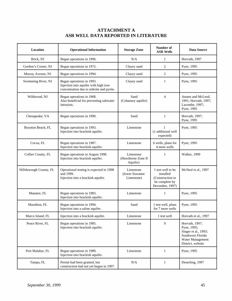
September 30, 1999 45
ATTACHMENT AASR WELL DATA REPORTED IN LITERATURE
Location Operational Information Storage Zone Data SourceNumber of ASR Wells
Brick, NJ Began operations in 1996. N/A 1 Horvath, 1997
Gordon’s Corner, NJ Began operations in 1972. Clayey sand 2 Pyne, 1995
Murray Avenue, NJ Began operations in 1994. Clayey sand 2 Pyne, 1995
Swimming River, NJ Began operations in 1993. Clayey sand 1 Pyne, 1995Injection into aquifer with high ironconcentration due to siderite and pyrite.
Wildwood, NJ Began operations in 1968. Sand 4 Amans and McLeod,Also beneficial for preventing saltwater (Cohansey aquifer) 1991; Horvath, 1997;intrusion. Lacombe, 1997;
Pyne, 1995
Chesapeake, VA Began operations in 1990. Sand 1 Horvath, 1997; Pyne, 1995
Boynton Beach, FL Began operations in 1993. Limestone 1 Pyne, 1995Injection into brackish aquifer. (1 additional well
expected)
Cocoa, FL Began operations in 1987. Limestone 6 wells, plans for Pyne, 1995Injection into brackish aquifer. 4 more wells
Collier County, FL Began operations in August 1998. Limestone 1 Walker, 1999Injection into brackish aquifer. (Hawthorne Zone II
Aquifer)
Hillsborough County, FL Operational testing is expected in 1998 Limestone 1 test well to be McNeal et al., 1997and 1999. (lower Suwanee installedInjection into a brackish aquifer. Limestone) (Construction to
be complete byDecember, 1997)
Manatee, FL Began operations in 1983. Limestone 1 Pyne, 1995Injection into brackish aquifer.
Marathon, FL Began operations in 1994. Sand 1 test well, plans Pyne, 1995Injection into a saline aquifer. for 7 more wells
Marco Island, FL Injection into a brackish aquifer. Limestone 1 test well Horvath et al., 1997
Peace River, FL Began operations in 1985. Limestone 9 Horvath, 1997; Injection into brackish aquifer. Pyne, 1995;
Singer et al., 1993;Southwest FloridaWater ManagementDistrict, website
Port Malabar, FL Began operations in 1989. Limestone 1 Pyne, 1995Injection into brackish aquifer.
Tampa, FL Permit had been granted, but N/A 1 Deuerling, 1997construction had not yet begun in 1997.
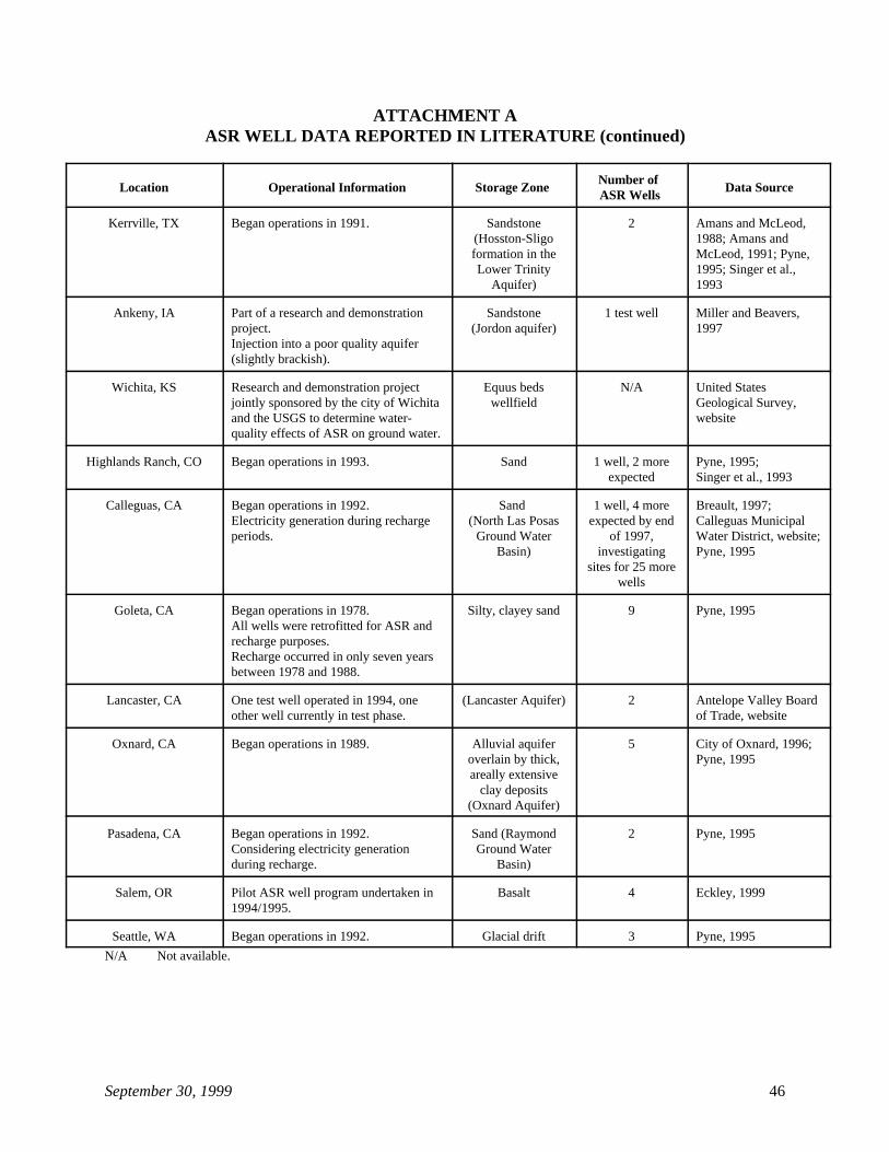
ATTACHMENT AASR WELL DATA REPORTED IN LITERATURE (continued)
Location Operational Information Storage Zone Data SourceNumber of ASR Wells
September 30, 1999 46
Kerrville, TX Began operations in 1991. Sandstone 2 Amans and McLeod,(Hosston-Sligo 1988; Amans andformation in the McLeod, 1991; Pyne,Lower Trinity 1995; Singer et al.,
Aquifer) 1993
Ankeny, IA Part of a research and demonstration Sandstone 1 test well Miller and Beavers,project. (Jordon aquifer) 1997Injection into a poor quality aquifer(slightly brackish).
Wichita, KS Research and demonstration project Equus beds N/A United Statesjointly sponsored by the city of Wichita wellfield Geological Survey,and the USGS to determine water- websitequality effects of ASR on ground water.
Highlands Ranch, CO Began operations in 1993. Sand 1 well, 2 more Pyne, 1995;expected Singer et al., 1993
Calleguas, CA Began operations in 1992. Sand 1 well, 4 more Breault, 1997;Electricity generation during recharge (North Las Posas expected by end Calleguas Municipalperiods. Ground Water of 1997, Water District, website;
Basin) investigating Pyne, 1995sites for 25 more
wells
Goleta, CA Began operations in 1978. Silty, clayey sand 9 Pyne, 1995All wells were retrofitted for ASR andrecharge purposes. Recharge occurred in only seven yearsbetween 1978 and 1988.
Lancaster, CA One test well operated in 1994, one (Lancaster Aquifer) 2 Antelope Valley Boardother well currently in test phase. of Trade, website
Oxnard, CA Began operations in 1989. Alluvial aquifer 5 City of Oxnard, 1996;overlain by thick, Pyne, 1995areally extensive
clay deposits(Oxnard Aquifer)
Pasadena, CA Began operations in 1992. Sand (Raymond 2 Pyne, 1995Considering electricity generation Ground Waterduring recharge. Basin)
Salem, OR Pilot ASR well program undertaken in Basalt 4 Eckley, 19991994/1995.
Seattle, WA Began operations in 1992. Glacial drift 3 Pyne, 1995
N/A Not available.
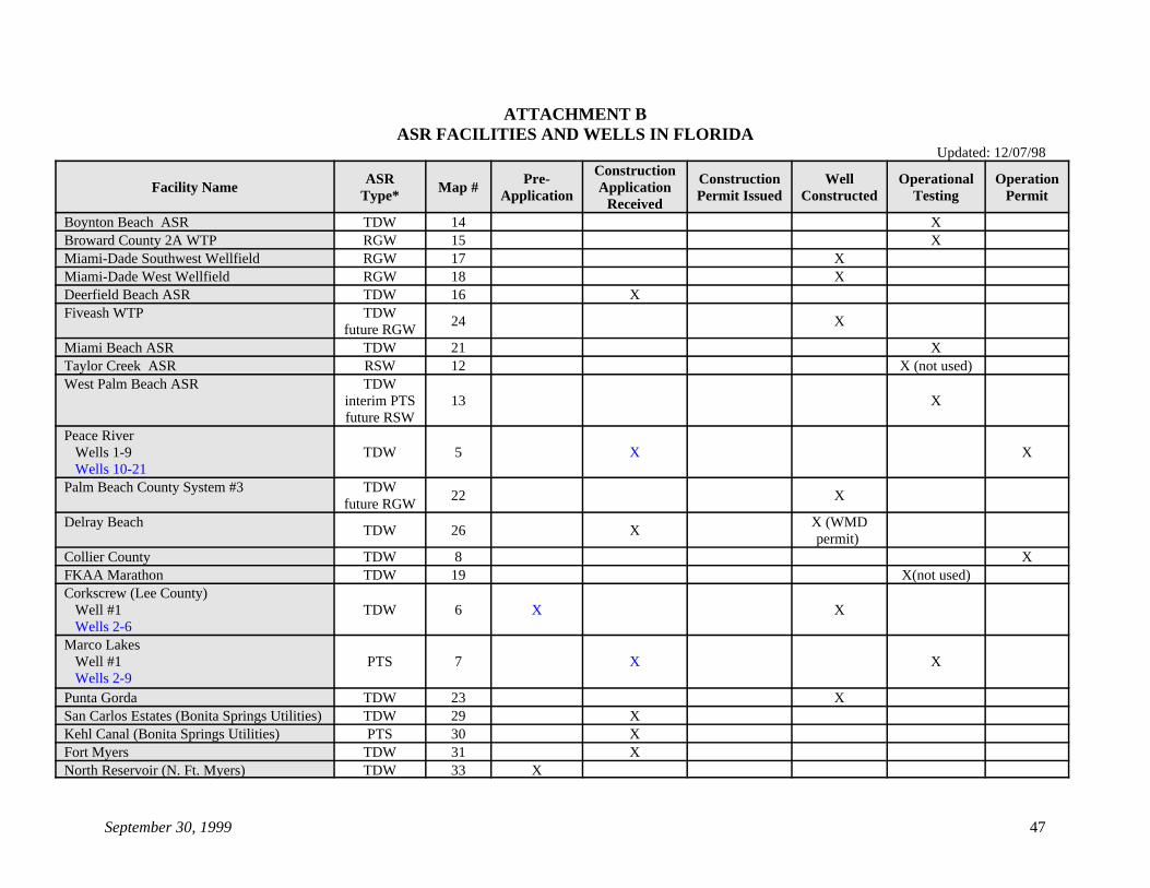
September 30, 1999 47
ATTACHMENT BASR FACILITIES AND WELLS IN FLORIDA
Updated: 12/07/98
Facility Name Map # ApplicationASR Pre- Construction Well Operational Operation
Type* Application Permit Issued Constructed Testing Permit
Construction
ReceivedBoynton Beach ASR TDW 14 XBroward County 2A WTP RGW 15 XMiami-Dade Southwest Wellfield RGW 17 XMiami-Dade West Wellfield RGW 18 XDeerfield Beach ASR TDW 16 XFiveash WTP TDW
future RGW24 X
Miami Beach ASR TDW 21 XTaylor Creek ASR RSW 12 X (not used)West Palm Beach ASR TDW
interim PTS 13 Xfuture RSW
Peace River Wells 1-9 TDW 5 X X Wells 10-21Palm Beach County System #3 TDW
future RGW22 X
Delray Beach X (WMDTDW 26 X
permit) Collier County TDW 8 XFKAA Marathon TDW 19 X(not used)Corkscrew (Lee County) Well #1 TDW 6 X X Wells 2-6Marco Lakes Well #1 PTS 7 X X Wells 2-9Punta Gorda TDW 23 XSan Carlos Estates (Bonita Springs Utilities) TDW 29 XKehl Canal (Bonita Springs Utilities) PTS 30 XFort Myers TDW 31 XNorth Reservoir (N. Ft. Myers) TDW 33 X
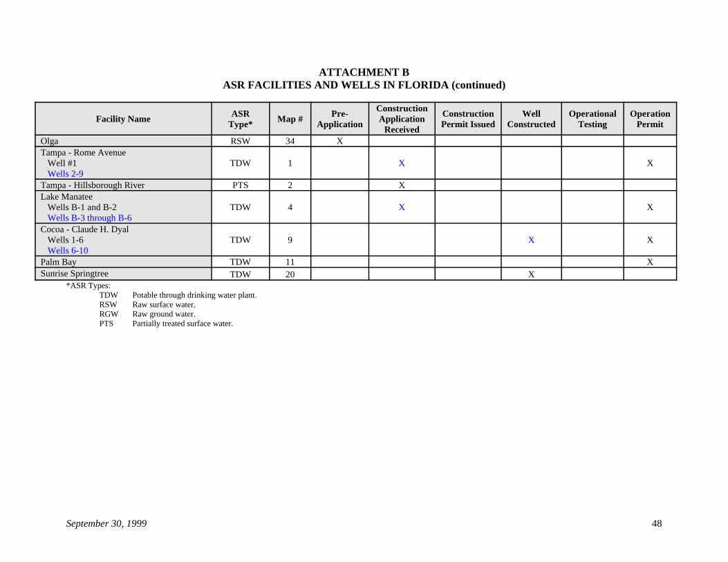
ATTACHMENT BASR FACILITIES AND WELLS IN FLORIDA (continued)
Facility Name Map # ApplicationASR Pre- Construction Well Operational Operation
Type* Application Permit Issued Constructed Testing Permit
Construction
Received
September 30, 1999 48
Olga RSW 34 XTampa - Rome Avenue Well #1 TDW 1 X X Wells 2-9Tampa - Hillsborough River PTS 2 XLake Manatee Wells B-1 and B-2 TDW 4 X X Wells B-3 through B-6Cocoa - Claude H. Dyal Wells 1-6 TDW 9 X X Wells 6-10Palm Bay TDW 11 XSunrise Springtree TDW 20 X
*ASR Types:TDW Potable through drinking water plant.RSW Raw surface water.RGW Raw ground water.PTS Partially treated surface water.
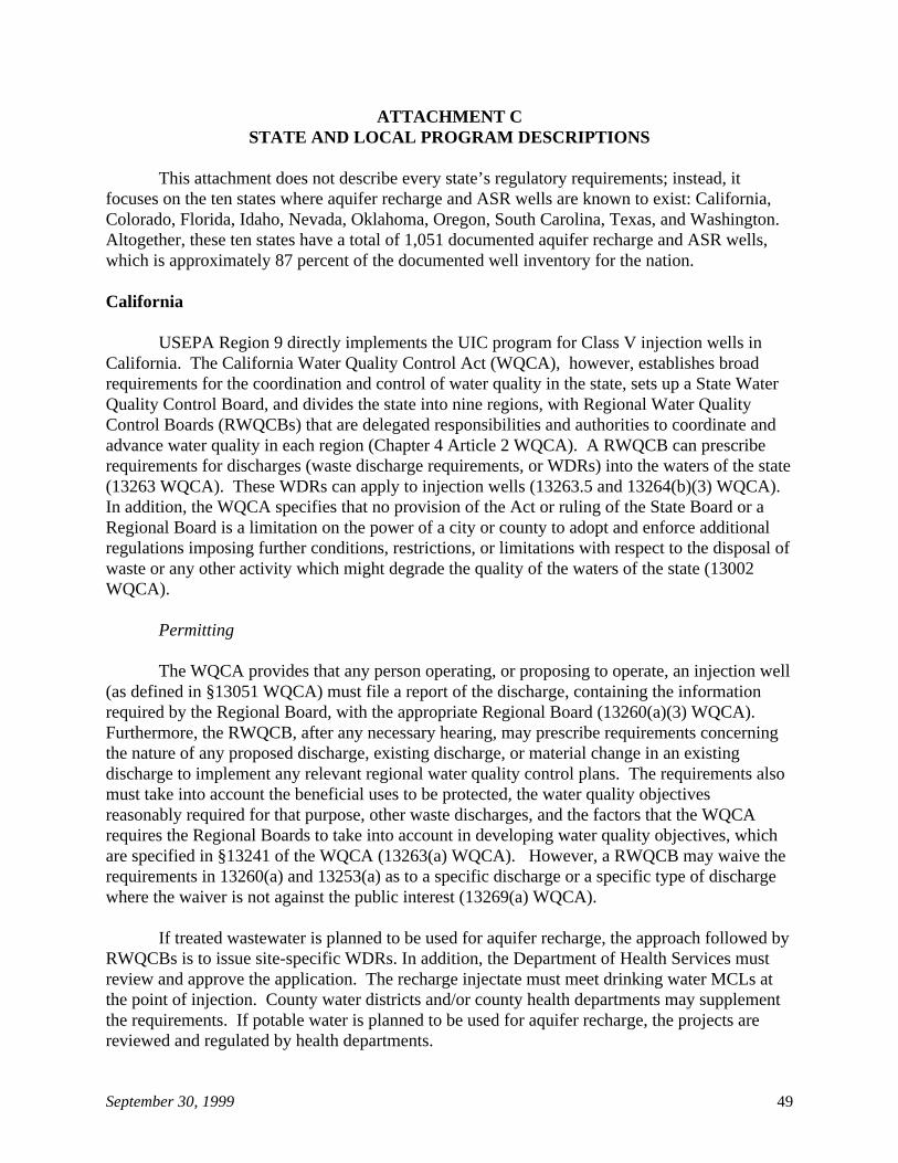
September 30, 1999 49
ATTACHMENT CSTATE AND LOCAL PROGRAM DESCRIPTIONS
This attachment does not describe every state’s regulatory requirements; instead, itfocuses on the ten states where aquifer recharge and ASR wells are known to exist: California,Colorado, Florida, Idaho, Nevada, Oklahoma, Oregon, South Carolina, Texas, and Washington. Altogether, these ten states have a total of 1,051 documented aquifer recharge and ASR wells,which is approximately 87 percent of the documented well inventory for the nation.
California
USEPA Region 9 directly implements the UIC program for Class V injection wells inCalifornia. The California Water Quality Control Act (WQCA), however, establishes broadrequirements for the coordination and control of water quality in the state, sets up a State WaterQuality Control Board, and divides the state into nine regions, with Regional Water QualityControl Boards (RWQCBs) that are delegated responsibilities and authorities to coordinate andadvance water quality in each region (Chapter 4 Article 2 WQCA). A RWQCB can prescriberequirements for discharges (waste discharge requirements, or WDRs) into the waters of the state(13263 WQCA). These WDRs can apply to injection wells (13263.5 and 13264(b)(3) WQCA). In addition, the WQCA specifies that no provision of the Act or ruling of the State Board or aRegional Board is a limitation on the power of a city or county to adopt and enforce additionalregulations imposing further conditions, restrictions, or limitations with respect to the disposal ofwaste or any other activity which might degrade the quality of the waters of the state (13002WQCA).
Permitting
The WQCA provides that any person operating, or proposing to operate, an injection well(as defined in §13051 WQCA) must file a report of the discharge, containing the informationrequired by the Regional Board, with the appropriate Regional Board (13260(a)(3) WQCA). Furthermore, the RWQCB, after any necessary hearing, may prescribe requirements concerningthe nature of any proposed discharge, existing discharge, or material change in an existingdischarge to implement any relevant regional water quality control plans. The requirements alsomust take into account the beneficial uses to be protected, the water quality objectivesreasonably required for that purpose, other waste discharges, and the factors that the WQCArequires the Regional Boards to take into account in developing water quality objectives, whichare specified in §13241 of the WQCA (13263(a) WQCA). However, a RWQCB may waive therequirements in 13260(a) and 13253(a) as to a specific discharge or a specific type of dischargewhere the waiver is not against the public interest (13269(a) WQCA).
If treated wastewater is planned to be used for aquifer recharge, the approach followed byRWQCBs is to issue site-specific WDRs. In addition, the Department of Health Services mustreview and approve the application. The recharge injectate must meet drinking water MCLs atthe point of injection. County water districts and/or county health departments may supplementthe requirements. If potable water is planned to be used for aquifer recharge, the projects arereviewed and regulated by health departments.
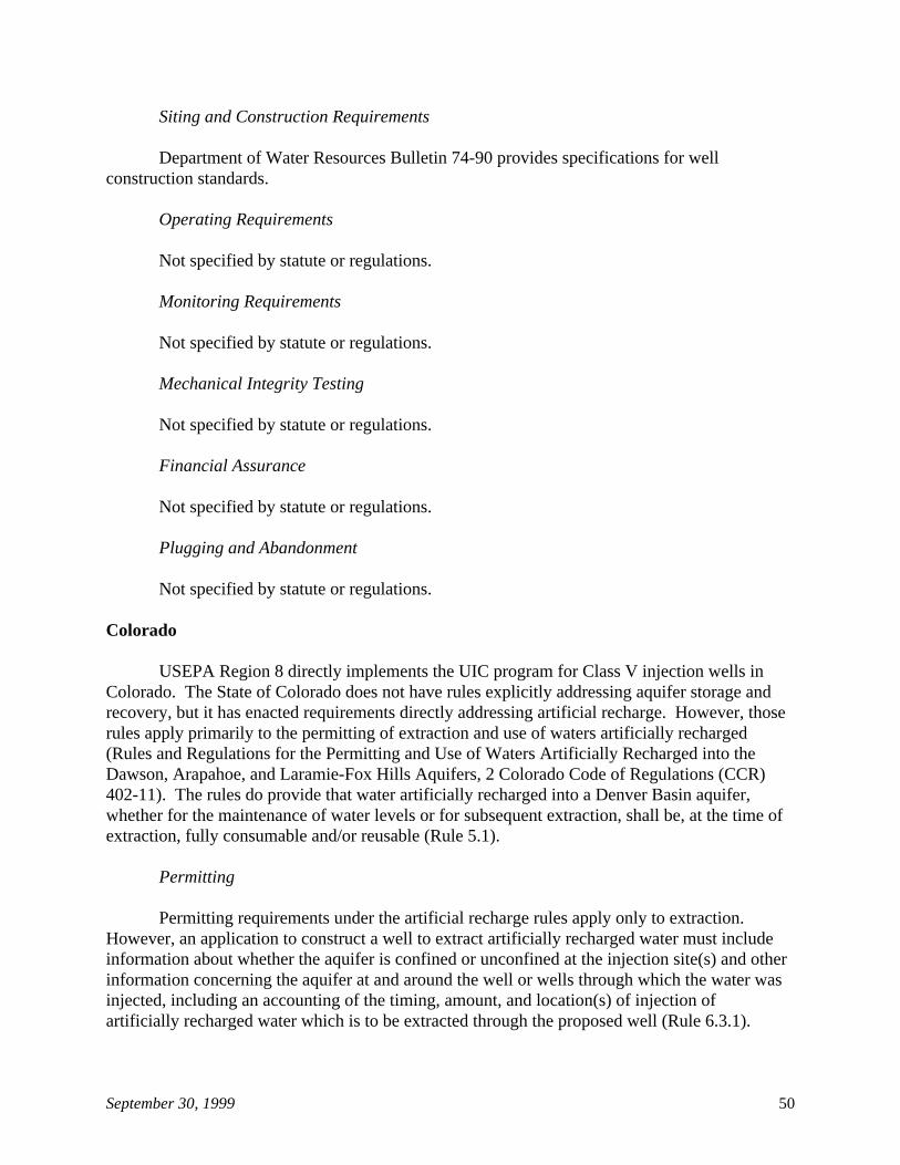
September 30, 1999 50
Siting and Construction Requirements
Department of Water Resources Bulletin 74-90 provides specifications for wellconstruction standards.
Operating Requirements
Not specified by statute or regulations.
Monitoring Requirements
Not specified by statute or regulations.
Mechanical Integrity Testing
Not specified by statute or regulations.
Financial Assurance
Not specified by statute or regulations.
Plugging and Abandonment
Not specified by statute or regulations.
Colorado
USEPA Region 8 directly implements the UIC program for Class V injection wells inColorado. The State of Colorado does not have rules explicitly addressing aquifer storage andrecovery, but it has enacted requirements directly addressing artificial recharge. However, thoserules apply primarily to the permitting of extraction and use of waters artificially recharged(Rules and Regulations for the Permitting and Use of Waters Artificially Recharged into theDawson, Arapahoe, and Laramie-Fox Hills Aquifers, 2 Colorado Code of Regulations (CCR)402-11). The rules do provide that water artificially recharged into a Denver Basin aquifer,whether for the maintenance of water levels or for subsequent extraction, shall be, at the time ofextraction, fully consumable and/or reusable (Rule 5.1).
Permitting
Permitting requirements under the artificial recharge rules apply only to extraction. However, an application to construct a well to extract artificially recharged water must includeinformation about whether the aquifer is confined or unconfined at the injection site(s) and otherinformation concerning the aquifer at and around the well or wells through which the water wasinjected, including an accounting of the timing, amount, and location(s) of injection ofartificially recharged water which is to be extracted through the proposed well (Rule 6.3.1).
September 30, 1999 51
Like almost all western states, Colorado issues permits for the extraction and use of bothsurface water and ground water. Permits for extraction and use must consider impacts toexisting wells and other water rights. The rules on permitting and use of waters artificiallyrecharged into the Dawson, Denver, Arapahoe, and Laramie-Fox Hills aquifers define extractionwell as an existing permitted well or a well that has been, or will be constructed, for the purposeof extracting artificially recharged water. When applied to an existing permitted well, this termmay describe a well which has been authorized for the extraction of an amount of water beyondthe amount of naturally occurring ground water authorized for withdrawal under the existingpermit (Rule 4.3.8). Use of totalizing flow meters is required for measuring the amount of allwater injected and extracted (Rule 5.7.1). The State Engineer accounts for water that isartificially recharged and administers the orderly withdrawal of such water to prevent injury toexisting water users and water rights holders.
Siting and Construction Requirements
Colorado’s water well construction rules (2. CCR 402-2) do not state explicitly that theyapply to artificial recharge wells, but because they apply to the construction of water wells, thestate applies them. A permit issued by the State Engineer is required prior to constructing a newor replacement well (Water Well Construction Rule 6).
Siting and construction requirements under the artificial recharge rules apply only toextraction. The water well construction rules contain detailed requirements concerning welllocation and minimum well construction standards (Rule 10). They include specifications forwell casing, sealing and grouting, and disinfection (Rule 10.4 - 10.9 and Rule 17).
Operating Requirements
The wells used for artificial recharge and/or extraction are required to have totalizingflow meters installed to measure the amount of all water injected and extracted (Rule 5.7). If themeter is not operational, the well may not be operated.
Monitoring Requirements
Not specified by statute or regulations.
Mechanical Integrity Testing
Not specified by statute or regulations.
September 30, 1999 52
Financial Assurance
Not specified by statute or regulations.
Plugging and Abandonment
Not specified by statute or regulations.
Florida
Florida is a UIC Primacy State for Class V wells. Chapter 62-528 of the FloridaAdministrative Code (FAC), effective June 24, 1997, establishes the state's UIC program, andPart V of Chapter 62-528 (62-528.600 to 62-528.900) addresses criteria and standards for ClassV wells. Class V wells are grouped for purposes of permitting into eight categories. Aquiferrecharge wells fall into Group 2. Wells associated with an aquifer storage and recovery systemfall into Group 7.
Permitting
Underground injection through a Class V well is prohibited except as authorized bypermit by the Department of Environmental Protection. Owners and operators are required toobtain a Construction/Clearance Permit before receiving permission to construct. The applicantis required to submit detailed information, including well location and depth, description of theinjection system and of the proposed injectate, and any proposed pretreatment. When site-specific conditions indicate a threat to a USDW, additional information must be submitted. Thestate generally issues letters of authorization, even when potable water is injected and no permitis required. The letter of authorization can include specific conditions with respect to thestandards that must be met by the injected water, monitoring requirements for flow rate andpressure, sampling of monitoring well, and reporting. Finally, all Class V wells are required toobtain a plugging and abandonment permit.
In addition, local Water Management Districts and/or County EnvironmentalManagement Departments also review applications for aquifer storage and recovery wells.
Siting and Construction Requirements
Specific construction standards for Class V wells have not been enacted by Florida,because of the variety of Class V wells and their uses. Instead, the state requires the well to bedesigned and constructed for its intended use, in accordance with good engineering practices,and approves the design and construction through a permit. The state can apply any of thecriteria for Class I wells to the permitting of Class V wells, if it determines that without suchcriteria the Class V well may cause or allow fluids to migrate into a USDW and cause a violationof the state’s primary or secondary drinking water standards, which are contained in Chapter 62-550 of the FAC. However, if the injectate meets the primary and secondary drinking waterquality standards and the minimum criteria contained in Rule 62-520-400 of the FAC, Class Iinjection well permitting standards will not be required.
September 30, 1999 53
Class V wells are required to be constructed so that their intended use does not violatethe water quality standards in Chapter 62-520 FAC at the point of discharge, provided that thedrinking water standards of 40 CFR Part 142 (1994) are met at the point of discharge.
Operating Requirements
All Class V wells are required to be used or operated in such a manner that does notpresent a hazard to a USDW. Pretreatment of injectate must be performed, if necessary to ensurethe fluid does not violate the applicable water quality standards in 62-520 FAC.
Monitoring Requirements
Monitoring generally will be required for Group 2 and 7 wells, unless the wells injectfluids that meet the primary and secondary drinking water standards in 62-550 FAC and theminimum criteria in Rule 62-520, and the injection fluids have been processed through apermitted drinking water treatment facility (62-528.615 (1)(a)2 FAC). Monitoring frequencywill be based on well location and the nature of the injectate and will be addressed in the permit.
Mechanical Integrity Testing
Not specified by statute or regulations.
Financial Assurance
Not specified by statute or regulations.
Plugging and Abandonment
The owner or operator of any Class V well must apply for a plugging and abandonmentpermit when the well is no longer used or usable for its intended purpose. Plugging must beperformed by a licensed water well contractor.
Idaho
Idaho is a UIC Primacy State for Class V wells and has promulgated regulations for theUIC Program in the Idaho Administrative Code (IDAPA), Title 3, Chapter 3. Deep injectionwells are defined as more than 18 feet in vertical depth below the land surface (37.03.03.010.11IDAPA). Wells are further classified, with Class V Subclass 5R21 defined as aquifer rechargewells (37.03.03.025.01.m IDAPA).
September 30, 1999 54
Permitting
Construction and use of shallow injection wells is authorized by rule, provided thatinventory information is provided and use of the well does not result in unreasonablecontamination of a drinking water source or cause a violation of the state’s water qualitystandards that would affect a beneficial use (37.03.03.025.03.d. IDAPA). Construction and useof Class V deep injection wells is authorized by permit (37.03.03.025.03.c IDAPA). Theregulations outline detailed specifications for the information that must be supplied in a permitapplication (37.03.03.035 IDAPA).
Operating Requirements
Standards for the quality of injected fluids and criteria for location and use areestablished for rule-authorized wells, as well as for wells requiring permits. The rules are basedon the premise that if the injected fluids meet MCLs for drinking water for physical, chemical,and radiological contaminants at the wellhead, and if ground water produced from adjacentpoints of diversion for beneficial use meets the water quality standards found in Idaho’s “WaterQuality Standards and Wastewater Treatment Requirements,” 16.01.02 IDAPA, administered bythe Idaho Department of Health and Welfare, the aquifer will be protected from unreasonablecontamination. State officials may, when it is deemed necessary, require specific injection wellsto be constructed and operated in compliance with additional requirements (37.03.03.050.01IDAPA (Rule 50)). Rule-authorized wells “shall conform to the drinking water standards at thepoint of injection and not cause any water quality standards to be violated at the point ofbeneficial use” (37.03.03.050.04.d IDAPA).
Monitoring Requirements
Monitoring, record keeping, and reporting may be required if state officials find that thewell may adversely affect a drinking water source or is injecting a contaminant that could havean unacceptable effect upon the quality of the ground waters of the state (37.03.03.055 IDAPA(Rule 55)).
Mechanical Integrity Testing
Not specified by statute or regulations.
Financial Assurance
There are no financial responsibility requirements for rule-authorized wells. Permittedwells are required by the permit rule to demonstrate financial responsibility through aperformance bond or other appropriate means to abandon the injection well according to theconditions of the permit (37.03.03.35.03.e IDAPA).
September 30, 1999 55
Plugging and Abandonment
The Idaho Department of Water Resources (IDWR) has prepared “General Guidelines forAbandonment of Injection Wells,” which are not included in the regulatory requirements. IDWRexpects to approve the final abandonment procedure for each well. The General Guidelinesrecommend the following:
C Pull the casing, if possible. If the casing is not pulled, cut the casing a minimum of twofeet below the land surface.
C The total depth of the well should be measured.
C If the casing is left in place, it should be perforated and neat cement with up to 5 percentbentonite can be pressure-grouted to fill the hole. As an alternative, when the casing isnot pulled, course bentonite chips or pellets may be used. If the well extends into theaquifer, the chips or pellets must be run over a screen to prevent any dust from enteringthe hole. No dust is allowed to enter the bore hole because of the potential for bridging. Perforation of the casing is not required under this alternative.
C If the well extends into the aquifer, a clean pit-run gravel or road mix may be used to fillthe bore up to ten feet below the top of the saturated zone or ten feet below the bottom ofcasing, whichever is deeper, and cement grout or bentonite clay used to the surface. Theuse of gravel may not be allowed if the lithology is undetermined or unsuitable.
C A cement cap should be placed at the top of the casing if it is not pulled, with a minimumof two feet of soil overlying the filled hole/cap.
C Abandonment of the well must be witnessed by an IDWR representative.
Nevada
Nevada is a UIC Primacy State for Class V wells in which the Division of EnvironmentalProtection (DEP) administers the UIC Program. In addition, the State Engineer is authorized toregulate the use of underground water, and projects for recharge and storage and recovery fallunder that jurisdiction.
Nevada Revised Statutes (NRS) §§ 445A.300 - 445A.730 and regulations under theNevada Administrative Code (NAC) §§ 445A.810 - 445A.925 establish the state’s basic UICProgram. The injection of fluids through a well into any waters of the state, includingunderground waters, is prohibited without a permit issued by DEP (445A.465 NRS), althoughthe statute allows both general and individual permits (445A.475 NRS and 445A.480 NRS). Furthermore, injection of a fluid that degrades the physical, chemical, or biological quality of theaquifer into which it is injected is prohibited, unless the DEP exempts the aquifer and the federalUSEPA does not disapprove the exemption within 45 days after notice of it (445A.850 NRS). Regulations, particularly Chapter 445A NAC, “Underground Injection Control,” define andelaborate these statutory requirements.
September 30, 1999 56
In addition, Chapter 534 of the Nevada Revised Statutes, “Underground Water andWells” addresses recharge and storage and recovery activities.
Permitting
The UIC regulations specify detailed information that must be provided in support ofpermit applications, including proposed well location, description of geology, construction plans,proposed operating data on rates and pressures of injection, analysis of injectate, analysis of fluidin the receiving formation, proposed injection procedures, and corrective action plan (445A.867NAC). The DEP may, however, modify the permit application information required for a ClassV well.
The underground water statute provides that the State Engineer will supervise all wellstapping artesian water or water in definable underground aquifers, except wells for domesticpurposes that do not require a permit (534.030.4 NRS). The State Engineer may establish aground water basin water board to advise on approval of applications to issue permits to drillwells or take related actions (534.035 NRS). Persons seeking to sink or bore a well in any basinor portion thereof in the state designated by the State Engineer must first obtain a permit fromthe State Engineer (534.050 NRS). The statute also provides that any person seeking to operatea project for recharge, storage, and recovery of water must obtain a permit from the StateEngineer. The State Engineer must determine that the project is hydrologically feasible and thatit will not cause harm to users of land or other water within the area of hydrological effect of theproject (534.250 NRS). A permit application must supply detailed information about theproject, including the following:
C Evidence of financial and technical capacity;
C The source, quality and annual quantity of water proposed to be recharged, and thequality of the receiving water; and
C A study that demonstrates the area of hydrological effect of the project, that the project ishydrologically feasible, that the project will not cause harm to users of land and waterwithin the area of hydrological effect; the percent of recoverable water.
The permit will specify the capacity and plan of operation of the project, any requiredmonitoring, and any conditions (534.270 NRS).
Siting and Construction Requirements
The State of Nevada specifies that all injection wells must be situated on a well-drainedsite not subject to inundation by a 100-year flood and sited in such a way that the well injectsinto a formation that is separated from any USDW by a confining zone that is free of knownopen faults or fractures within the area of review. It must be cased from the finished surface tothe top of the zone for injection and cemented to prevent movement of fluids into or betweenUSDWs. All injections must be through tubing set on a mechanical packer and the packer must
September 30, 1999 57
be set between the top of the zone for injection and the bottom of the next highest USDW and asclose as possible to the top of the injected interval (445A.908 NAC).
Operating Requirements
Injection of a fluid that degrades the physical, chemical, or biological quality of theaquifer into which it is injected is prohibited, unless the DEP exempts the aquifer and theUSEPA does not disapprove the exemption within 45 days after notice of it (445A.850 NRS).
Monitoring Requirements
Monitoring frequency for injection pressure, pressure of the annular space, rate of flow,and volume of injected fluid is specified by the permit for Class V wells. Analysis of injectedfluid must be conducted with sufficient frequency to yield representative data. Mechanicalintegrity testing is required once each 5 years, by a specified method (445A.916 NAC).
Mechanical Integrity Testing
Not specified by statute or regulations.
Financial Assurance
A bond is required in favor of the state for the costs of plugging and abandonment of thewell, except that the bond may be waived for Class V wells upon adequate proof of financialresponsibility (445A.871 NAC).
Plugging and Abandonment
A plugging and abandonment plan and cost estimate must be prepared for each well, andreviewed annually. Before abandonment, a well must be plugged with cement in a manner thatwill not allow the movement of fluids into or between USDWs (445A.923 NAC).
Oklahoma
Oklahoma is a UIC Primacy State for Class V wells. The state has incorporated byreference into the Oklahoma Administrative Code (OAC) those parts of 40 CFR Part 124, andParts 144 to 148 that apply to the UIC program (252-652-1-3 OAC).
Permitting
Applicants for Class V injection well facilities are required to perform ground watermonitoring, provide an analysis of injected fluids and a description of the geologic strata throughwhich and into which injection is taking place, and provide any addition information that theapplicant believes is necessary to comply with 40 CFR 144.12 (252:652-5-3 OAC).
September 30, 1999 58
Siting and Construction Requirements
Not specified by statute or regulations.
Operating Requirements
Not specified by statute or regulations.
Monitoring Requirements
Not specified by statute or regulations.
Mechanical Integrity Testing
Not specified by statute or regulations.
Financial Assurance
Not specified by statute or regulations.
Plugging and Abandonment
Not specified by statute or regulations.
Oregon
Oregon is a Primacy State for UIC Class V wells. The UIC program is administered bythe Department of Environmental Quality (DEQ). Under the State’s Administrative Rules(OAR) pertaining to underground injection, “underground injection activity” means any activityinvolving underground injection of fluids, including waste disposal wells and ground waterrecharge wells. A “waste disposal well” is defined as any bored, drilled, driven or dug hole,whose depth is greater than its largest surface dimension, which is used or is intended to be usedfor disposal of sewage, industrial, agricultural, or other wastes and includes drain holes,drywells, cesspools and seepage pits, along with other underground injection wells (340-044-0005(22) OAR). Construction and operation of a waste disposal well is prohibited without awater pollution control facility (WPCF) permit. Certain categories of wells are prohibitedentirely. Wells used for underground injection activities that allow the movement of fluids into aUSDW if such fluids may cause a violation of any primary drinking water regulation orotherwise create a public health hazard or have the potential to cause significant degradation ofpublic waters are prohibited (340-044-0015(4)(d) OAR). The rules also provide that anyunderground injection activity which may cause, or tend to cause, pollution of ground water maybe approved by DEQ in addition to other permits or approvals required by other federal, state, orlocal agencies.
OAR contain special provisions administered by the Water Resources Departmentaddressing ASR and artificial ground water recharge (OAR 690 Division 350). ASR is defined
September 30, 1999 59
as the storage of water from a separate source that meets drinking water standards in a suitableaquifer for later recovery and not having as one of its primary purposes the restoration of theaquifer (690-350-0010(1)(a) OAR). Artificial ground water recharge is defined as theintentional addition of water diverted from another source to a ground water reservoir (690-350-0110(1) OAR).
Permitting
ASR requires a limited license for ASR testing before a permanent ASR permit may beobtained (690-350-0010(2) OAR). The limited license may cover ASR testing for a single wellor same-aquifer wells in a wellfield. The injection source water for ASR is required to complywith drinking water standards, treatment requirements, and performance standards established bythe state Health Department or maximum measurable levels established by the EnvironmentalQuality Commission, whichever are more stringent. Conditions are placed in the limited licenseor permit to minimize, to the extent technically feasible, practical, and cost-effective, theconcentration of constituents in the injection source water that are not naturally present in theaquifer. No license or permit may establish concentration limits for water to be injected for ASRin excess of standards established by the Health Department or the Environmental QualityCommission (690-350-0010(6)(a)-(c) OAR). If the injection source water contains regulatedconstituents that are detected at greater than 50 percent of the established levels, the ASR limitedlicense or permit may require the permittee to employ technically feasible, practical, and cost-effective methods to minimize concentrations of such constituents in the injection source water. Constituents that are associated with disinfection of the water may be injected into the aquifer upto the standards established in the state. Further restrictions may be placed on certainconstituents if the Water Resources Department finds that they will interfere with or pose athreat to the maintenance of the water resources of the state for present or future beneficial uses.
An application for a limited license must specify the proposed source for injection water,maximum diversion rate, maximum injection rate at each well, maximum storage volume,maximum storage duration, and maximum withdrawal rate at each well. It must specify theproposed beneficial use or the intended disposal method for the recovered water. Access towater for injection must be evidenced by a completed water availability statement from the localwatermaster, results from the DEQ's water availability model, or citation of an existing waterright. If the applicant is not the holder of the water right for the proposed ASR testing,permission for use must be obtained. Applicants are encouraged to protect their ground watersupply through the development of a Wellhead Protection plan (690-350-0020 OAR).
The proposed ASR testing program must include water quality sampling, qualityassurance/quality control, and water level monitoring. The proposed system design must includewell construction information for any injection wells. Detailed preliminary hydrogeologicinformation must be provided. Detailed information must be provided on the quality of thesource water and the quality of the receiving aquifer water. Application for a permanent ASRpermit requires submission of detailed information on all of the topics included in the applicationfor a limited license (690-350-0030 OAR). The Water Resources Department consults with theHealth Department and DEQ about the completeness of the applications for a limited license orpermit.
September 30, 1999 60
An application for a ground water recharge permit must include all of the informationrequired under OAR 690-310-0040. Use of artificially recharged waters requires a secondaryground water permit specifying the maximum diversion rate and volume of withdrawals andallowable uses of stored recharged water (690-350-0130 OAR).
Siting and Construction Requirements
The permit application must include the proposed system design, including wellconstruction information, the wellhead assembly, piping system for injection and recovery, andother conceptual design components of the system. A licensed professional must develop thisinformation (690-350-0030(4)(b)(B) OAR).
Operating Requirements
Not specified by statute or regulations.
Monitoring Requirements
Not specified by statute or regulations.
Mechanical Integrity Testing
Not specified by statute or regulations.
Financial Assurance
Not specified by statute or regulations.
Plugging and Abandonment
The state UIC requirements provide that upon discontinuance of use or abandonment awaste disposal well is required to be rendered completely inoperable by plugging and sealing thehole. All portions of the well which are surrounded by “solid wall” formation must be pluggedand filled with cement grout or concrete. The top portion of the well must be effectively sealedwith cement grout or concrete to a depth of at least 18 feet below the surface of the ground, or ifthis method of sealing is not effective by a manner approved by the DEQ. The Water ResourcesDepartment’s requirements for ASR and aquifer recharge wells do not address plugging orabandonment.
September 30, 1999 61
South Carolina
South Carolina is a UIC Primacy State for Class V wells and the UIC program isimplemented by the Department of Health and Environmental Control (DHEC). The UICregulations, found in Chapter 61 of the State Code of Regulations, divide Class V wells into twogroups, with aquifer recharge wells found in group A.
Permitting
Class V.A. wells, which include recharge wells used to replenish the water in an aquifer,are prohibited except as authorized by permit (R61-87.10.E.(1)(b) and (2)). The permitapplication must include a description of the activities to be conducted, the name, address, andlocation of the facility, the names and other information pertaining to the owner and operator, adescription of the business, and proposed operating data, including average and maximum dailyrate and volume of fluid to be injected, average and maximum injection pressure, and source andan analysis of the chemical, physical, biological, and radiological characteristics of the injectedfluid; and drawings of the surface and subsurface construction of the well (R61-87.13.G(2)). The movement of fluids containing wastes or contaminants into USDWs as a result of injectionis prohibited if the waste or contaminant may cause a violation of any drinking water standard orotherwise adversely affect the health of persons (R61-87.5).
Siting and Construction Requirements
Siting and operating criteria and standards for Class V.A wells require logs and tests,which will be specified by DHEC in the permit, to identify and describe USDWs and theinjection formation (R61-87.14).
Injection may not commence until construction is complete, the permittee has submittednotice of completion to DHEC, and DHEC has inspected the well and found it in compliance (R61-87.13U).
Operating Requirements
Operating requirements for Class V.A wells are the same as those for Class II and IIIwells (R61-87.14). DHEC will establish maximum injection volumes and pressures and suchother permit conditions as necessary to assure that fractures are not initiated in the confiningzone adjacent to a USDW and to assure compliance with operating requirements (R61-87.13V).
Monitoring Requirements
Monitoring requirements will be specified in the permit. Monitoring requirements forClass V.A wells are the same as those for Class III wells, and may include monitoring wells(R61-87.14.G). Quarterly reporting of monitoring results is required to DHEC (R61-87.14.I(1)).
September 30, 1999 62
Mechanical Integrity Testing
Prior to granting approval for operation, DHEC will require a satisfactory demonstrationof mechanical integrity. Tests will be performed at least every 5 years (R61-87.14.G).
Financial Assurance
Not specified by statute or regulations.
Plugging and Abandonment
A plugging and abandonment plan must be prepared and approved by DHEC (R61-87.15).
Texas
Texas is a UIC Primacy State for Class V wells. The Injection Well Act (Chapter 27 ofthe Texas Water Code) and Title 3 of the Natural Resources Code provide statutory authority forthe UIC program. Regulations establishing the UIC program are found in Title 30, Chapter 331of the Texas Administrative Code (TAC). Aquifer recharge wells used to replenish water in anaquifer are specifically defined as Class V wells (331.11 (a)(4)(F) TAC). Aquifer storage wellsused for the injection of water for storage and subsequent retrieval for beneficial use are alsospecifically defined as Class V wells (331.11 (a)(4)(K) TAC).
Permitting
Underground injection is prohibited, unless authorized by permit or rule (331.7 TAC). By rule, injection into a Class V well is authorized, although the Texas Natural ResourcesControl Commission (TNRCC) may require the owner or operator of a well authorized by rule toapply for and obtain an injection well permit (331.9 TAC). No permit or authorization by rule isallowed where an injection well causes or allows the movement of fluid that would result in thepollution of a USDW. A permit or authorization by rule must include terms and conditionsreasonably necessary to protect fresh water from pollution (331.5 TAC).
Siting and Construction Requirements
All Class V wells are required to be completed in accordance with explicit specificationsin the rules, unless otherwise authorized by the TNRCC. These specifications are:
C A form provided either by the Water Well Drillers Board or the TNRCC must becompleted.
C The annular space between the borehole and the casing must be filled from ground levelto a depth of not less than 10 feet below the land surface or well head with cement slurry. Special requirements are imposed in areas of shallow unconfined ground water aquifersand in areas of confined ground water aquifers with artesian head.
September 30, 1999 63
C In all wells where plastic casing is used, a concrete slab or sealing block must be placedabove the cement slurry around the well at the ground surface; and the rules includeadditional specifications concerning the slab.
C In wells where steel casing is used, a slab or block will be required above the cementslurry, except when a pitless adaptor is used, and the rules contain additionalrequirements concerning the adaptor.
C All wells must be completed so that aquifers or zones containing waters that differsignificantly in chemical quality are not allowed to commingle through the borehole-casing annulus or the gravel pack and cause degradation of any aquifer zone.
C The well casing must be capped or completed in a manner that will prevent pollutantsfrom entering the well.
C When undesirable water is encountered in a Class V well, the undesirable water must besealed off and confined to the zone(s) of origin (331.132 TAC).
Operating Requirements
None specified. Chapter 331, Subpart H, “Standards for Class V Wells” addresses onlyconstruction and closure standards (331.131 to 331.133 TAC).
Monitoring Requirements
Not specified by statute or regulations.
Mechanical Integrity Testing
Injection may be prohibited for Class V wells that lack mechanical integrity. TheTNRCC may require a demonstration of mechanical integrity at any time if there is reason tobelieve mechanical integrity is lacking. The TNRCC may allow plugging of the well or requirethe permittee to perform additional construction, operation, monitoring, reporting, and correctiveactions which are necessary to prevent the movement of fluid into or between USDWs caused bythe lack of mechanical integrity. Injection may resume on written notification from the TNRCCthat mechanical integrity has been demonstrated (331.4 TAC).
Financial Assurance
Chapter 27 of the Texas Water Code, “Injection Wells,” enacts financial responsibilityrequirements for persons to whom an injection well permit is issued. A performance bond orother form of financial security may be required to ensure that an abandoned well is properlyplugged (§ 27.073). Detailed financial responsibility requirements also are contained in Chapter331, Subchapter I of the state’s UIC regulations (331.141 to 331.144 TAC). A permittee isrequired to secure and maintain a performance bond or other equivalent form of financial
September 30, 1999 64
assurance or guarantee to ensure the closing, plugging, abandonment, and post-closure care ofthe injection operation. However, the requirement, unless incorporated into a permit, appliesspecifically only to Class I and Class III wells (331.142 TAC).
Plugging and Abandonment
Plugging and abandonment of a well authorized by rule is required to be accomplished inaccordance with §331.46 TAC (331.9 TAC). In addition, closure standards specific to Class Vwells provide that closure is to be accomplished by removing all of the removable casing andfilling the entire well with cement to land surface. Alternatively, if the use of the well is to bepermanently discontinued, and if the well does not contain “undesirable” water, the well may befilled with fine sand, clay, or heavy mud followed by a cement plug extending from the landsurface to a depth of not less than 10 feet. If the use of a well that does contain undesirablewateris to be permanently discontinued, either the zone(s) containing undesirable water or the freshwater zone(s) must be isolated with cement plugs and the remainder of the wellbore filled withsand, clay, or heavy mud to form a base for a cement plug extending from the land surface to adepth of not less than 10 feet (331.133 TAC).
Washington
Washington is a UIC Primacy State for Class V wells. Chapter 173-218 of theWashington Administrative Code (WAC) establishes the state's UIC program. Under thisprogram, the policy of the Department of Ecology is to maintain the highest possible standards toprevent the injection of fluids that may endanger ground waters which are available forbeneficial uses or which may contain fewer than 10,000 mg/l total dissolved solids. Consistentwith that policy, all new Class V injection wells that inject industrial, municipal, or commercialwaste fluids into or above a USDW are prohibited (172-218-090(1) WAC). Existing wells mustobtain a permit to operate.
In addition, the state has enacted standards for direct ground water recharge projectsusing reclaimed water (Water Reclamation and Reuse Standards, Section 3). These rulesprimarily address the standards and treatment requirements for the reclaimed water, wheninjected into potable ground water and when injected into nonpotable ground water. For potableground water, the requirements also include construction standards for withdrawal facilities,requiring them to comply with 173-136 and 173-150 WAC. The rules include reclaimed watersampling and analysis and monitoring requirements, operational requirements for thereclamation plant, disinfection requirements, mandatory retention time prior to withdrawal, andground water monitoring requirements (Articles 3 to 6). However, these rules do not addressrequirements for injection and/or withdrawal wells, except for the requirement pertaining towells withdrawing water from potable aquifers.
September 30, 1999 65
Permitting
A permit must specify conditions necessary to prevent and control injection of fluids intothe waters of the state, including all known, available, and reasonable methods of prevention,control, and treatment; applicable requirements in 40 CFR Parts 124, 144, 146; and anyconditions necessary to preserve and protect USDWs. Any injection well that causes or allowsthe movement of fluid into a USDW that may result in a violation of any primary drinking waterstandard under 40 CFR Part 141 or that may otherwise adversely affect the beneficial use of aUSDW is prohibited (173-218-100 WAC).
Siting and Construction Requirements
The state has promulgated minimum standards for construction and maintenance of wells(173-160-010 through -560 WAC). However, injection wells regulated under Chapter 173-218are specifically exempted from these constructions standards (173-160-010(3)(e) WAC).
Operating Requirements
The water quality standards for ground waters establish an antidegradation policy. Theinjectate must meet the state’s ground water standards at the point of compliance (173-200-030WAC).
Monitoring Requirements
Not specified by statute or regulations.
Mechanical Integrity Testing
Not specified by statute or regulations.
Financial Assurance
Not specified by statute or regulations.
Plugging and Abandonment
All wells not in use must be securely capped so that no contamination can enter the well(173-160-085 WAC).
September 30, 1999 66
REFERENCES
Amans, L.C. and J. McLeod. 1988. Kerrville, Texas--A Case Study for Aquifer StorageRecovery. In International Symposium on Class V Injection Well Technology, held in LasVegas, Nevada. Underground Injection Practices Council, 203-221. September 13-15, 1988.
Antelope Valley Board of Trade. 1997. Aquifer Storage and Recovery Testing Continues. Antelope Valley Business News. Available: http://www.avbot.org/avdn/mar97/aquifer.html.
Atkinson, S.F., G.D. Miller, and D.S. Curry. 1986. Salt-water Intrusion, Status and Potential inthe Contiguous United States. Chelsea, Michigan: Lewis Publishers.
Bouwer, H., R.D.G. Pyne, and J.A. Goodrich. 1990. Recharging Groundwater. CivilEngineering. American Society of Civil Engineers, 1:6: 63-66.
Bloetscher, F. 1999. Comments on the May 17, 1999 Draft of The Class V UndergroundInjection Control Study: Salt Water Intrusion Barrier Wells Information Summary. FloridaGovernmental Utility Authority. June 16, 1999.
Breault, R.L. 1997. Project Management During Design and Construction of an AquiferStorage & Recovery Wellfield. Proceedings of AWRA Symposium, Conjunctive Use of WaterResources: Aquifer Storage and Recovery, Long Beach, California. Herdon, Virginia: AmericanWater Resources Association, 357-363. October 19-23, 1997.
Bruington, A.E. 1968. The Amelioration of Prevention of Salt-Water Intrusion in Aquifers-Experience in Los Angeles County, California. Salt-water Encroachment into Aquifers:Proceedings of the Limited Professional Symposium, Louisiana State University, Baton Rouge,Louisiana, May 4-5, 1967. Baton Rouge: Louisiana Water Resources Research Institute Bulletin3. October 1968.
Calleguas Municipal Water District. Las Posas Basin Aquifer Storage and Recovery Project.Available: http://www.calleguas.com/lpb.html.
Castro, J.E. and L.R. Gardner. 1997. “A Geochemical Model for the Aquifer Storage andRecovery Project at Myrtle Beach, SC.” Proceedings of AWRA Symposium, Conjunctive Useof Water Resources: Aquifer Storage and Recovery, held in Long Beach, California, October 19-23, 1997. American Water Resources Association. pp 201-210.
Centennial Water and Sanitation District. 1998. Water Analysis Report of Water SamplesCollected at Location K01: Well A-6 Recharge on February 11, 1998, April 23, 1998, and July28, 1998. September 30, 1998.
City of Oxnard. 1996. Annual Water Quality Report: Water Quality Program. Oxnard,California.
September 30, 1999 67
City of Salem. 1999. Letter from Mr. Paul Eckley, Chief Utilities Engineer, City of Salem, toMr. Donn Miller, Hydrogeologist, Oregon Water Resources Department re 1998 Annual Reportfor ASR Limited License #001. February 11, 1999.
Crook, J., T. Asano, and M. Nellor. 1991. Groundwater Recharge with Reclaimed Water inCalifornia. Municipal Wastewater Reuse: Selected Readings on Water Reuse. 67-74. Washington, D.C.: U.S. Environmental Protection Agency. EPA 430/09-91-022.
Culp, R.L.. 1981. Treatment Processes to Meet Water Reuse Requirements. Water Engineeringand Management 28:4: 72-76.
Deuerling, R. 1997. Florida Department of Environmental Regulations. Memorandum toAnhar Karimjee, Office of Water, U.S. Environmental Protection Agency, Tallahassee, FL. November 14, 1997.
Deuerling, Rich. 1999. Comments on the April 30, 1999 Draft of the Class V UndergroundInjection Control Study: Aquifer Recharge Well Information Summary. State of Florida. June/July 1999.
Dickenson, J.M. 1997. ASR and Ground water Basin Management. Proceedings of AWRASymposium, Conjunctive Use of Water Resources: Aquifer Storage and Recovery. Long Beach,California. Herndon, Virginia: American Water Resources Association, 155-162. October 19-23, 1997.
Driscoll, F. G. 1986. Groundwater and Wells (Second Edition). Johnson Division. St. Paul,Minnesota.
Eckley, Paul. 1999. Comments on the May 14, 1999 Draft of the Class V UndergroundInjection Control Study: Aquifer Storage and Recovery Well Information Summary. OregonPublic Works Department. City of Salem, Oregon. June 9, 1999.
Fairchild, D.M. 1985. Multi-Purpose Approach to Ground Water Management. Proceedings ofthe Association of Ground Water Scientists and Engineers, Southern Regional WaterConference, San Antonio, Texas. Worthington, OH: National Water Well Association. September 18-19, 1985.
Florida Department of Environmental Protection (FDEP). 1998. Map titled Aquifer Storage andRecovery Facilities. December 1998. Table titled Aquifer Storage and Recovery Facilities inFlorida. Updated: December 7, 1998.
Freeze, R. A. and J. A. Cherrry. 1979. Groundwater. Printice Hall, Inc. Englewoods Cliffs,New Jersey.
Griffis, C.L. 1976. Artificial Recharge in the Grand Prairie, Arkansas. Bulletin 810,Agricultural Experiment Station, University of Arkansas, Fayetteville, Arkansas. August, 1976.
September 30, 1999 68
Hamlin, S.M. 1987. Hydraulic/Chemical Changes During Ground-Water Recharge byInjection. Groundwater 25:3: 267-274.
Horvath, Lloyd. 1997. ViroGroup, Inc. Memorandum to Kim Clemente, The Cadmus Group,Inc. List of ASR projects that ViroGroup has undertaken, 1997. Cape Coral, FL.
Horvath, L.E., M.S. Pearce, and H.J. Losch. 1997. Using Aquifer Storage and Recovery toMeet Seasonally Fluctuating Water Demand and Water Availability Cycles at Marco Island,Florida. Proceedings of AWRA Symposium, Conjunctive Use of Water Resources: AquiferStorage and Recovery, Long Beach, California. Herndon, Virginia: American Water ResourcesAssociation, 61-70. October 19-23, 1997.
Kazman, R.G. 1967. Perspectives in Artificial Recharge. American Water ResourcesAssociation, Proceedings Series #4, pp. 187-192.
Lacombe, P.J. 1997. Artificial Recharge of Ground Water by Well Injection for Storage andRecovery, Cape May County, New Jersey, 1958-92. Proceedings of AWRA Symposium,Conjunctive Use of Water Resources: Aquifer Storage and Recovery, Long Beach, California. Herndon, Virginia: American Water Resources Association, 33-41. October 19-23, 1997.
Lichtler, W.F., D. Stannard, and E. Kourna. 1980. “Investigation of Artificial Recharge ofAquifers in Nebraska.” Water-Resources Investigations: 80-93. U.S. Geological Survey. Reston, VA.
Lucas, M. and K. McGill. 1997. “Aquifer Treatment Methods for Preventing IronConcentrations in the Recovered Water From Aquifer Storage and Recovery Wells Installed inClayey Sand Aquifers of the Atlantic Coastal Plain.” Proceedings of AWRA Symposium,Conjunctive Use of Water Resources: Aquifer Storage and Recovery. Held in Long Beach,California October 19-23, 1997. American Water Resources Association. pp 449-458.
McNeal, M.B., A.E. Fox, N.J. LoPriesti, and K.E. Coates. 1997. Seasonal Storage of HighQuality Reclaimed Water. Proceedings of AWRA Symposium, Conjunctive Use of WaterResources: Aquifer Storage and Recovery, Long Beach, California. Herndon, Virginia:American Water Resources Association, 427-435. October 19-23, 1997.
Memphis Light, Gas, and Water Division, 1997. Letter from Mr. Charles Pickel, Manager, Gasand Water Engineering, to Ms. Robin Bell, Manager, Underground Injection Program,Tennessee Department of Environment and Conservation, Division of Water Supply, March 5,1997.
Miller, T.J. and R.R. Beavers. 1997. ASR Using a Deep Midwestern Aquifer: Des Moines(Iowa) Water Works ASR Demonstration Project. Proceedings of AWRA Symposium,Conjunctive Use of Water Resources: Aquifer Storage and Recovery, Long Beach, California. Herndon, Virginia: American Water Resources Association, 89-98. October 19-23, 1997.
September 30, 1999 69
North Carolina Division of Water Resources. 1996. Strategic Management Implications ofWater Reclamation and Reuse on Water Resources.
O’Hare, M.P., D.M. Fairchild, P.A. Hajali, and L.W. Canter. 1986. Artificial Recharge ofGroundwater. Chelsea, MI: Lewis Publishers.
Olson, Gregg. 1999. Comments on the April 30, 1999 Draft of the Class V UndergroundInjection Control Study: Aquifer Recharge Well Information Summary. USEPA Region 9. June 23, 1999.
Palmer, R., D. Wendell, A. Hutchinson, and T. Foreman. 1997. “Optimization of ASROperations in a Nitrate and PCE Contaminated Aquifer.” Proceedings of AWRA Symposium,Conjunctive Use of Water Resources: Aquifer Storage and Recovery, held in Long BeachCalifornia, October 19-23, 1997. American Water Resources Association. pp 3-11.
Pitt, W.A.J. and S. Magenheimer. 1997. ASR Technology: Avoidance and Solutions to AquiferClogging Problems. Proceedings of AWRA Symposium, Conjunctive Use of Water Resources:Aquifer Storage and Recovery, Long Beach, California. Herndon, Virginia: American WaterResources Association, 251-260. October 19-23, 1997.
Powers, J. Patrick. 1992. Construction Dewatering: New Methods and Applications. SecondEdition. John Wiley & Sons, Inc.
Priest, Barbara. 1999. UIC Program Coordinator, Water Quality Division, Oregon Departmentof Environmental Quality. Telephone Conversation with Maribelle Rodríguez, ICF Consulting. September 9 and 14, 1999.
Pyne, R.D.G. 1995. Ground water Recharge and Wells: A Guide to Aquifer Storage Recovery. Boca Raton, Florida: Lewis Publishers.
Schaefer, V.R., DeBoer, D.E., and Emmons, P.J. 1994. Huron Project of the High Plains StatesDemonstration Program. Artificial Recharge of Ground Water, II: Proceedings of the SecondInternational Symposium on Artificial Recharge of Ground Water. American Society of CivilEngineers.
Shea-Albin, V. 1997. “Summary of info from the Report to Congress on the High PlainsAquifer Project (prepared by USEPA to be part of the preamble).” USEPA Region 8. Denver,CO. Correspondence to Anhar Karimjee, Office of Water, U.S. Environmental ProtectionAgency. October 31, 1997.
Singer, P.C., et al. Examining the Impact of Aquifer Storage and Recovery on DBPs. Journal ofthe American Water Works Association, 85-94. November 1993.
Sniegocki, R.T. and Brown, R.F. 1970. Clogging in Recharge Wells, Causes and Cures. Proceedings Artificial Ground Water Recharge Conference. Water Res. Assn. England. 337.
September 30, 1999 70
South Dakota State University. 1993. Memorandum Rule Authorization for Huron Project ofthe High Plains States Groundwater Demonstration Program. Addressed to Mr ArnoldBoettcher, USEPA. March 26, 1993.
Southwest Florida Water Management District. The Peace River Option: A Balance BetweenNature and People. Issue Paper No. 8. Available:http://www.dep.state.fl.us/swfwmd/SWFI008.html.
Terada, Calvin. 1999. Final Modified Inventories for Class V UIC Study-- Idaho, Oregon, andWashington. E-mail from USEPA Region 10 to Anhal Karimjee, USEPA Office of GroundWater and Drinking Water. February 24, 1999.
Tennessee Department of Environment and Conservation (TDEC). 1996a. Letter from Mr.Justin Wilson, Commissioner, Tennessee Department of Environment and Conservation,Division of Water Supply, to Mr. Charles Pickel, Manager. Gas and Water Engineering,Memphis Light, Gas, and Water Division. Re: UIC Class V Permit, MLGW, Shelby County,May 30, 1996.
Tennessee Department of Environment and Conservation (TDEC). 1996b. UndergroundInjection Control Permit - Authorization to Operate a Class V Injection Well, issued to MemphisLight, Gas, and Water Division, May 30, 1996.
Tennessee Department of Environment and Conservation. 1996c. Memorandum from Ms.Robin Bell, Manager, Underground Injection Program, Tennessee Department of Environmentand Conservation, Division of Water Supply, to Mr. Justin Wilson, Commissioner, TennesseeDepartment of Environment and Conservation, Division of Water Supply: Re: Request reviewand approval to issue Class V Underground Injection Control (UIC) Permit, May 8, 1996.
Texas Department of Water Resources. 1984. Underground Injection Operations in Texas: AClassification and Assessment of Underground Injection Activities. Chapter 8: ArtificialRecharge Wells. December 1984.
Todd, D. K. 1980. Groundwater Hydrology (Second Edition). John Wiley & Sons.
U.S. Bureau of Reclamation. No date #1. High Plains States Groundwater DemonstrationProgram, Interim Report.
U.S. Bureau of Reclamation. No date #2. Huron Project of the High Plains States GroundwaterDemonstration Program Progress Report for the Period November 1, 1991 to May 31, 1992.
U.S. Bureau of Reclamation. 1996. Hueco Bolson Recharge Demonstration Study Summary. April 1996.
U.S. Department of the Interior. 1996. A Comprehensive Plan for the Restoration of theEverglades. January 19, 1996.
September 30, 1999 71
USEPA. 1997. Source Water Assessment and Programs Guidance. Office of Water. Washington, D.C. EPA 816-R-97-009. August 1997.
U.S. Geological Survey. Water-Quality Effects of Aquifer Storage and Recharge of the EquusBeds at the Ground-Water Recharge Demonstration Project Site Near Wichita, Kansas. ProjectNumber KS194. Available: http://www-ks.cr.usgs.gov/Kansas/studies/project.html.
Walker, Charles W. 1999. Comments on the May 14, 1999 Draft of the Class V UndergroundInjection Control Study: Aquifer Storage and Recovery Well Information Summary. MissimerInternational, Inc. June 17, 1999.
Warner, D. L. 1965. Deep well injection of liquid waste. Environmental Health Series, WaterSupply and Pollution Control, No. 999-WP-21. U.S. Department of Health, Education andWelfare. Cincinnati, Ohio.
Wilson, Karen. 1999. Comments on the May 14, 1999 Draft of the Class V UndergroundInjection Control Study: Aquifer Storage and Recovery Well Information Summary. USEPARegion 4. June/July, 1999.