the circulate architecture: avoiding workflow bottlenecks
TRANSCRIPT

Cluster Comput (2009) 12: 221–235DOI 10.1007/s10586-009-0072-4
The Circulate architecture: avoiding workflow bottlenecks causedby centralised orchestration
Adam Barker · Jon B. Weissman · Jano I. van Hemert
Received: 19 December 2008 / Accepted: 2 January 2009 / Published online: 24 January 2009© Springer Science+Business Media, LLC 2009
Abstract As the number of services and the size of datainvolved in workflows increases, centralised orchestrationtechniques are reaching the limits of scalability. In the clas-sic orchestration model, all data passes through a centralisedengine, which results in unnecessary data transfer, wastedbandwidth and the engine to become a bottleneck to the ex-ecution of a workflow.
This paper presents and evaluates the Circulate architec-ture which maintains the robustness and simplicity of cen-tralised orchestration, but facilitates choreography by allow-ing services to exchange data directly with one another. Cir-culate could be realised within any existing workflow frame-work, in this paper, we focus on WS-Circulate, a Web ser-vices based implementation.
Taking inspiration from the Montage workflow, a num-ber of common workflow patterns (sequence, fan-in and fan-out), input to output data size relationships and network con-figurations are identified and evaluated. The performanceanalysis concludes that a substantial reduction in commu-nication overhead results in a 2–4 fold performance benefitacross all patterns. An end-to-end pattern through the Mon-tage workflow results in an 8 fold performance benefit and
A. Barker (�)Department of Engineering Science, University of Oxford,Oxford, UKe-mail: [email protected]
J.B. WeissmanUniversity of Minnesota, Minneapolis, MN, USAe-mail: [email protected]
J.I. van HemertNeSC, School of Informatics, University of Edinburgh,Edinburgh, UKe-mail: [email protected]
demonstrates how the advantage of using the Circulate ar-chitecture increases as the complexity of a workflow grows.
Keywords Workflow · Workflow optimisation · Webservices · Decentralised orchestration
1 Introduction
Efficiently executing large-scale, data-intensive workflowscommon to scientific applications must take into accountthe volume and pattern of communication. For example,in Montage [12] an all-sky mosaic computation can re-quire at least 2–8 TB of data movement. Standard work-flow tools based on a centralised enactment engine, such asTaverna [20] and OMII BPEL Designer [24] can easily be-come a performance bottleneck for such applications, extracopies of the data (intermediate data) are sent that consumenetwork bandwidth and overwhelm the central engine. In-stead, a solution is desired that permits data output fromone stage to be forwarded directly to where it is neededat the next stage in the workflow. It is certainly possibleto develop an optimised workflow system from scratch thatimplements this kind of optimisation. In contrast workflowsystems based on concrete industrial standards offer a dif-ferent set of benefits: they have a much larger and wideruser base, which allows the leverage of a greater availabilityof supported tools and application components. This paperexplores the extent to which the benefits of each approachcan be realised. Can a standards-based workflow systemachieve the performance optimisations of custom systems?And what are the trade-offs?
This paper explores these questions in the context of Webservices, a widely-promoted standard for building distrib-uted workflow applications based on a suite of simple stan-

222 Cluster Comput (2009) 12: 221–235
dards (XML, WSDL, SOAP, etc.) designed to facilitate ser-vice interoperability. This paper does not address the perfor-mance limitations inherent in SOAP, an issue well addressedby other groups [1, 6, 9].
Workflow can be described from the view of a single par-ticipant using orchestration or from a global perspective us-ing choreography. Web service orchestration enables Webservices to be composed together in predefined patterns, de-scribed using an orchestration language and executed onan orchestration engine. Orchestrations can span multipleapplications and/or organisations and result in long-lived,transactional processes. Services themselves have no knowl-edge of their involvement in a higher level application andtherefore need no alteration before enactment. Importantly,Web service orchestrations are described from the view of asingle participant (which can be another Web service) andtherefore a central process always acts as a controller tothe involved services. Orchestration languages explicitly de-scribe the interactions between Web services by identifyingmessages, branching logic and invocation sequences. TheBusiness Process Execution Language (BPEL) [23] is an ex-ecutable business process modelling language and the cur-rent de-facto standard way of orchestrating Web services.BPEL has broad industrial support from companies suchas IBM, Microsoft and Oracle, with concrete implementa-tions.
Service choreography on the other hand is more collabo-rative in nature. A service choreography is a description ofthe externally observable peer-to-peer interactions that ex-ist between services, therefore choreography does not relyon a central coordinator. A choreography model describesmulti-party collaboration and focuses on message exchange;each Web service involved in a choreography knows exactlywhen to execute its operations and with whom to interact.A choreography definition can be used at design-time to en-sure interoperability between a set of peer services from aglobal perspective, meaning that all participating servicesare treated equally, in a peer-to-peer fashion. The Web Ser-vices Choreography Description Language (WS-CDL) [14]is an XML-based language that can be used to describe thecommon and collaborative observable behaviour of multipleservices that need to interact in order to achieve a sharedgoal. WS-CDL is a W3C Candidate Recommendation.
This paper presents the Circulate architecture, a hybridsolution that “eliminates the middle man” by adopting anorchestration model of central control, but a choreographymodel of optimised distributed data transport. Our architec-ture could be realised within any existing workflow frame-work, even custom systems. In this paper, we focus on a Webservice based implementation for the evaluation. To explorethe benefits of the hybrid approach for data-intensive appli-cations, a set of workflow patterns and input-output relation-ships common to scientific applications (e.g. Montage) are
used in isolation and combination. The performance analy-sis concludes that a substantial reduction in communicationoverhead results in a 2–4 fold performance benefit across allpatterns. An end-to-end pattern through the Montage work-flow demonstrates how the advantage of using the Circulatearchitecture increases when patterns are used in combinationwith another, resulting in a 8 fold performance benefit.
2 Scientific workflow patterns
To identify data-centric scientific workflow patterns, theMontage application has been used. It is representative ofa class of large-scale data-intensive scientific workflows.Montage constructs custom “science-grade” astronomicalimage mosaics from a set of input image samples [12].The inputs to the workflow include the images in standardFITS format (a file format used throughout the astronomycommunity), and a “template header file” that specifies themosaic to be constructed. The workflow can be thought ofas having three parts, including re-projection of each in-put image to the coordinate space of the output mosaic,background rectification of the re-projected images, and co-addition to form the final output mosaic [8].
A typical montage workflow is depicted in Fig. 1. Thisworkflow consists of the following six components (with in-put/output relationships listed):
1. mProject: reprojects a single image to the coordinate sys-tem defined in a header file (output = input)
2. mDiff/mFitPlane: finds the difference between two im-ages and fits a plane to the difference image (output =15–20% of a typical image for each image triplet)
3. mConcatFit: a simple concatenation of the plane fit para-meters from multiple mDiff/mFitPlane jobs into a singlefile (see 4)
4. mBgModel: models the sky background using the planefit parameters from mDiff/mFitPlane and computes pla-nar corrections for the input images that will rectify thebackground across the entire mosaic (output = a subsetof inputs are output from mConcatFit and mBgModel)
5. mBackground: rectifies the background in a single image(output = input)
6. mAdd: co-adds a set of reprojected images to produce amosaic as specified in a template header file (output =70–90% the size of inputs put together).
Montage illustrates several features of data-intensive sci-entific workflows. First, Montage can result in huge dataflow requirements. For example, a small input file is 1.5 MBand a small Montage application can consist of hundreds ofinput files, a larger problem, 10–100 K image files, all inputin the mProject phase. The intermediate data can be 3 timesthe size of the input data. And a big problem, e.g. an all-sky

Cluster Comput (2009) 12: 221–235 223
Fig. 1 Montage Use-casescenario
mosaic can result in 2–8 TB of data. Such a problem mightbe run daily. Second, Montage contains workflow patternscommon to many scientific applications:
1. Fan-in: Involves mapping multiple sources to a singlesink (N:1 relationship), e.g. mDiff/mFitPlane → mCon-catFit.
2. Fan-out: The reverse pattern of fan-in, data from a singlesource is sent to multiple sinks (1:N relationship), e.g.mBgModel → Background.
3. Sequence: This pattern involves the chaining of servicestogether, where the output of one service invocation isused directly as input to another, i.e. serially (1:1 rela-tionship). The data flows as a pipeline with no data trans-formations, e.g. mConcat → mBgModel.
Large-scale scientific workflows such as Montage mayalso have significant computational requirements that mustbe considered in deployment. In this paper, we consider op-timisation of workflow patterns as representative of a classof large-scale data-intensive scientific workflows. We focusonly on the orchestrations and techniques required to reducethe cost of communication, assuming the computational re-sources for executing the workflow have been identified.
3 Hybrid workflow architecture
The majority of workflow research has focused on ser-vice orchestration for implementing service orchestrations,where both control and data flow pass through a centralisedserver. There are a plethora of orchestration frameworkswhich will automate these tasks, examples of which canbe found in the Business Process Modelling communitythrough BPEL, in the Life Sciences through Taverna [20]and in the computational Grid community through Pega-sus [8], Triana [22] and Kepler [18]. For a summary refer
to [3]. Choreography, although an established concept is aless well researched and implemented architecture.
This paper proposes the Circulate architecture, based oncentralised control flow, distributed data flow [16]. The Cir-culate architecture sits between a purely centralised solution(orchestration) and a purely decentralised solution (chore-ography). A centralised orchestration engine issues controlflow messages to Web services taking part in the workflow,however enrolled Web services can pass data flow messagesamongst themselves, like a peer-to-peer model. This modelmaintains the robustness and simplicity of centralised or-chestration but facilities choreography by avoiding the needto pass large quantities of intermediate data through a cen-tralised server.
Circulate is based on proxies, a lightweight, non-intrusivepiece of middleware, which provides a gateway and stan-dard API to Web service invocation. A proxy allows Webservices to exchange data flow messages directly with oneanother thereby avoiding transferring them through a cen-tralised server. Proxies are installed as “near” as possible toenrolled Web services; by near we mean preferably on thesame Web server or network domain, so that communicationbetween a proxy and a Web service takes place over a localnetwork. Depending on the preference of an administrator, aproxy can be responsible for one Web service, 1:1 or manyWeb services, 1:N, illustrated by Fig. 2.
Proxies themselves are exposed through a WSDL inter-face, allowing them to be built into workflows or higher levelapplications, such as any other Web service. As everythingis exposed through a WSDL interface, this means that work-flows can use a combination of proxies and vanilla Web ser-vices.
Proxies are controlled by a centralised orchestration en-gine which is executing an arbitrary workflow language,e.g. BPEL. However, only control flow messages are passed

224 Cluster Comput (2009) 12: 221–235
Fig. 2 1:N (left), 1:1 (middle), mixed components (right)
through the orchestration engine, larger data flow messagesare exchanged between proxies in a peer-to-peer fashion, un-less a proxy is explicitly told to do otherwise. Proxies ex-change references to the data with the orchestration engineand pass the real data directly to where it is required for thenext service invocation; this allows the orchestration engineto monitor the progress and make changes to the executionof a workflow. Unlike a pure choreography model, Circulateallows integration with centralised workflow systems mak-ing it easier to detect and handle failures.
Furthermore the architecture offers the following soft-ware engineering advantages:
• Transition is non-disruptive: The architecture can be de-ployed without disrupting current services and with min-imal changes in the workflows that make use of them.This flexibility allows a gradual change of infrastructures,where one could concentrate first on improving data trans-fers between services that handle large amounts data.
• Simplicity of deployment: The proxy services can be in-stalled without the need for writing any additional code.Configuration can be done remotely and dynamically. Itsimply requires the whereabouts of WSDL descriptionsfor any services that will be enabled through the proxy.
• Non-intrusive deployment: A proxy need not be installedon the same server as the Web service, and does not in-terfere with the current vanilla Web service as is the casewith pure choreography models, e.g. WS-CDL. However,to gain more performance, the proxy should be as near aspossible to the Web services it is enabling.
3.1 Proxy implementation and API
The Circulate architecture is available as an open-sourcetoolkit, WS-Circulate; implemented using a combination ofJava and the Apache Axis Web services toolkit [2]. Prox-ies are extremely simple to install and can be configuredremotely, no specialised programming needs to take placein order to exploit the functionality. WS-Circulate is multi-threaded and allows several applications to invoke methods
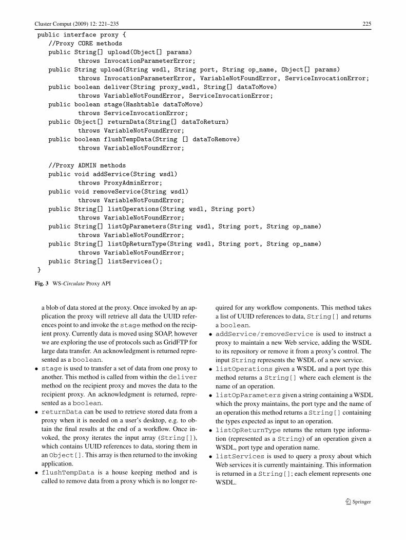
concurrently. A proxy has a thread pool and when that threadpool is full the request is placed on an input queue and dealtwith in First In First Out (FIFO) order. Results from Webservice invocations are stored at a proxy by tagging themwith a UUID (Universally Unique Identifier) and writingthem to disk. Proxies are made available through a standardWSDL interface, the Java representation of that interface isdisplayed in Fig. 3. All methods are invoked by an orches-tration engine except stage. A WS-Circulate proxy has thefollowing methods:
• invoke is the primary proxy method and provides agateway to Web service invocation. This method takes asinput: details of the Web service to be invoked, includingthe location of a WSDL, portType and operation name, fi-nally an array containing UUID references to data storedat the proxy; elements within the array must be in orderas they would be used as input to the Web service. Whenthis method is called the proxy retrieves the actual datathe UUID references point to, using these data as inputto the Web service invocation. Any results from the invo-cation are tagged with a UUID and written to disk at theproxy, this UUID is returned to the invoking application.
• upload provides functionality to upload data to a proxywhich is required as input to a Web service invocation,i.e. if the service is the first within a workflow and is notreliant on data from services further up the chain. Thismethod takes as input an Object[] that contains ac-tual data to be uploaded. Elements within this array mustconform to standard JAX-RPC supported types; the proxywill check this at runtime and exceptions will be thrownaccordingly. Uploaded data are tagged with a UUID andwritten to disk, the corresponding UUID set are returnedto the invoking application.
• deliver sets up data movement between proxies, mov-ing it closer to the source of a Web service invocation. Thefirst input parameter is a String containing the locationof the recipient proxy. Each element in the second inputparameter, String[] represents one UUID reference to
Cluster Comput (2009) 12: 221–235 225
Fig. 3 WS-Circulate Proxy API
a blob of data stored at the proxy. Once invoked by an ap-plication the proxy will retrieve all data the UUID refer-ences point to and invoke the stagemethod on the recip-ient proxy. Currently data is moved using SOAP, howeverwe are exploring the use of protocols such as GridFTP forlarge data transfer. An acknowledgment is returned repre-sented as a boolean.
• stage is used to transfer a set of data from one proxy toanother. This method is called from within the delivermethod on the recipient proxy and moves the data to therecipient proxy. An acknowledgment is returned, repre-sented as a boolean.
• returnData can be used to retrieve stored data from aproxy when it is needed on a user’s desktop, e.g. to ob-tain the final results at the end of a workflow. Once in-voked, the proxy iterates the input array (String[]),which contains UUID references to data, storing them inan Object[]. This array is then returned to the invokingapplication.
• flushTempData is a house keeping method and iscalled to remove data from a proxy which is no longer re-
quired for any workflow components. This method takesa list of UUID references to data, String[] and returnsa boolean.
• addService/removeService is used to instruct aproxy to maintain a new Web service, adding the WSDLto its repository or remove it from a proxy’s control. Theinput String represents the WSDL of a new service.
• listOperations given a WSDL and a port type thismethod returns a String[] where each element is thename of an operation.
• listOpParameters given a string containing a WSDLwhich the proxy maintains, the port type and the name ofan operation this method returns a String[] containingthe types expected as input to an operation.
• listOpReturnType returns the return type informa-tion (represented as a String) of an operation given aWSDL, port type and operation name.
• listServices is used to query a proxy about whichWeb services it is currently maintaining. This informationis returned in a String[]; each element represents oneWSDL.

226 Cluster Comput (2009) 12: 221–235
Proxies throw the following exceptions:
• InvocationParameterError is thrown if the ser-vice details (used an input) are not maintained by a proxyor if the types and/or number of parameters used in an in-put array do not match the actual Web service interfacethat the proxy is to invoke.
• VariableNotFoundError is thrown if there are anyreferences to a WSDL or data which cannot be found at aproxy.
• ServiceInvocationError will be thrown if thereare any faults with the actual Web service invocation, e.g.network failure, time-out etc.
• ProxyAdminError is thrown if an application is tryingto add a Web service which is already maintained by theproxy, or if the WSDL location is invalid.
3.2 Example application: fan-in pattern
Referring back to the Montage scenario, Fig. 4 is a UMLSequence diagram illustrating how the fan-in pattern (dis-cussed in Sect. 2) is orchestrated using a standard centralisedorchestration engine. In this pattern three sources arequeried for data, these data are combined and used as in-put to a final sink service, which processes these data andreturns a results set. Figure 5 illustrates the Circulate archi-tecture applied to the same pattern. In our examples threesource services are mapped to one sink, red arrowed linesadded to each of the diagrams illustrate data movement, datasizes added to the each of the figures are arbitrary and usedfor illustrative purposes only.
Using standard orchestration the query results (D1,D2, D3) from source1-source3 pass through the cen-tralised orchestration engine and are then used as input tothe sink service, which analyses the data and returns theresults (AD) back to the engine. Orchestration involves a to-tal data flow of 700 Mb.
With reference to Fig. 5, in order to orchestrate theworkflow using the Circulate architecture, the followingprocess takes place. The first step in the workflow patterninvolves making an invocation to the three source Web ser-vices source1-source3. However instead of contactingthe service directly, a call is made to a proxy (source-proxy) which has been installed on the same server as theWeb service. This is achieved through the invoke oper-ation passing the name of the Web service (source) andoperation (query) to be invoked, along with any requiredinput parameters. For readability portType details etc. havebeen omitted. The proxy spawns a new thread of control andinvokes the query operation on the source service, pass-ing in the necessary input parameters. The output from theservice invocation, is passed back to the proxy, tagged witha UUID (for reference later, e.g. retrieval, deletion etc.) andstored; there is a requirement that the proxy has enough diskspace to store the results. Instead of the proxy directly pass-ing the data back to the orchestration engine, the UUID isreturned. In a standard orchestration scenario the results ofthe Web service invocation would have first been moved tothe orchestration engine and then moved to where they areneeded at the sink Web service. However, as the proxy hasbeen installed on the same server as the source data, it canbe transferred locally between the proxy and the Web ser-vice and did not have to move over a Wide Area network,effectively saving a Wide Area hop. This process is repeated(either serially or in parallel) for source2 and source3which could be served through the same proxy or an inde-pendent proxy.
The output from the Web service invocations are neededas input to the next service in the workflow, in this case thesink Web service. The orchestration engine invokes thedeliver operation on the source-proxy passing in thethree UUID references along with the WSDL address of the
Fig. 4 UML Sequence diagramfor orchestrated fan-in pattern
Cluster Comput (2009) 12: 221–235 227
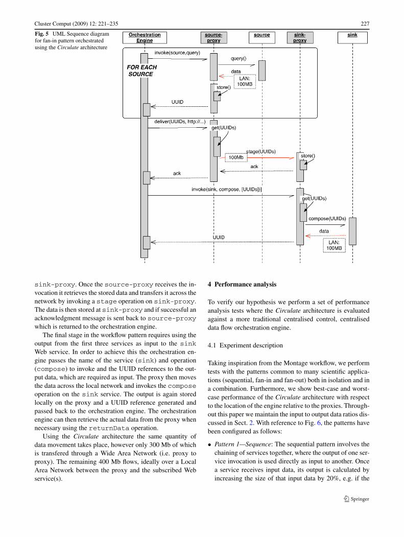
Fig. 5 UML Sequence diagramfor fan-in pattern orchestratedusing the Circulate architecture
sink-proxy. Once the source-proxy receives the in-vocation it retrieves the stored data and transfers it across thenetwork by invoking a stage operation on sink-proxy.The data is then stored at sink-proxy and if successful anacknowledgment message is sent back to source-proxywhich is returned to the orchestration engine.
The final stage in the workflow pattern requires using theoutput from the first three services as input to the sinkWeb service. In order to achieve this the orchestration en-gine passes the name of the service (sink) and operation(compose) to invoke and the UUID references to the out-put data, which are required as input. The proxy then movesthe data across the local network and invokes the composeoperation on the sink service. The output is again storedlocally on the proxy and a UUID reference generated andpassed back to the orchestration engine. The orchestrationengine can then retrieve the actual data from the proxy whennecessary using the returnData operation.
Using the Circulate architecture the same quantity ofdata movement takes place, however only 300 Mb of whichis transfered through a Wide Area Network (i.e. proxy toproxy). The remaining 400 Mb flows, ideally over a LocalArea Network between the proxy and the subscribed Webservice(s).
4 Performance analysis
To verify our hypothesis we perform a set of performanceanalysis tests where the Circulate architecture is evaluatedagainst a more traditional centralised control, centraliseddata flow orchestration engine.
4.1 Experiment description
Taking inspiration from the Montage workflow, we performtests with the patterns common to many scientific applica-tions (sequential, fan-in and fan-out) both in isolation and ina combination. Furthermore, we show best-case and worst-case performance of the Circulate architecture with respectto the location of the engine relative to the proxies. Through-out this paper we maintain the input to output data ratios dis-cussed in Sect. 2. With reference to Fig. 6, the patterns havebeen configured as follows:
• Pattern 1—Sequence: The sequential pattern involves thechaining of services together, where the output of one ser-vice invocation is used directly as input to another. Oncea service receives input data, its output is calculated byincreasing the size of that input data by 20%, e.g. if the
228 Cluster Comput (2009) 12: 221–235
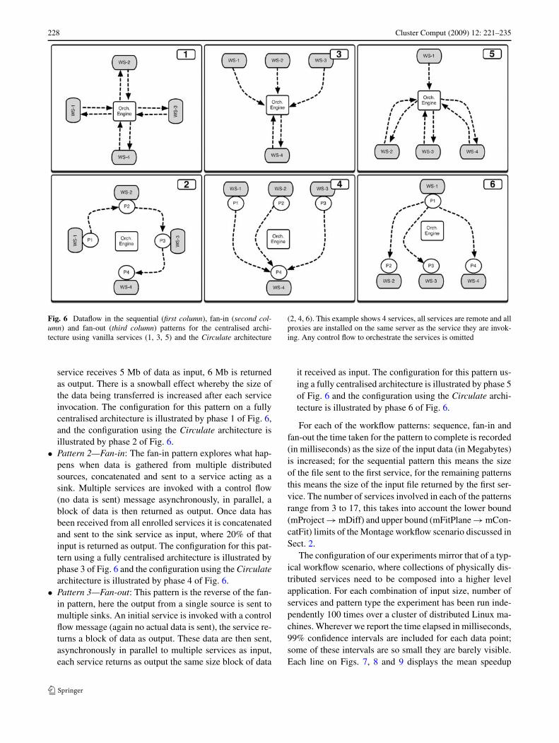
Fig. 6 Dataflow in the sequential (first column), fan-in (second col-umn) and fan-out (third column) patterns for the centralised archi-tecture using vanilla services (1, 3, 5) and the Circulate architecture
(2, 4, 6). This example shows 4 services, all services are remote and allproxies are installed on the same server as the service they are invok-ing. Any control flow to orchestrate the services is omitted
service receives 5 Mb of data as input, 6 Mb is returnedas output. There is a snowball effect whereby the size ofthe data being transferred is increased after each serviceinvocation. The configuration for this pattern on a fullycentralised architecture is illustrated by phase 1 of Fig. 6,and the configuration using the Circulate architecture isillustrated by phase 2 of Fig. 6.
• Pattern 2—Fan-in: The fan-in pattern explores what hap-pens when data is gathered from multiple distributedsources, concatenated and sent to a service acting as asink. Multiple services are invoked with a control flow(no data is sent) message asynchronously, in parallel, ablock of data is then returned as output. Once data hasbeen received from all enrolled services it is concatenatedand sent to the sink service as input, where 20% of thatinput is returned as output. The configuration for this pat-tern using a fully centralised architecture is illustrated byphase 3 of Fig. 6 and the configuration using the Circulatearchitecture is illustrated by phase 4 of Fig. 6.
• Pattern 3—Fan-out: This pattern is the reverse of the fan-in pattern, here the output from a single source is sent tomultiple sinks. An initial service is invoked with a controlflow message (again no actual data is sent), the service re-turns a block of data as output. These data are then sent,asynchronously in parallel to multiple services as input,each service returns as output the same size block of data
it received as input. The configuration for this pattern us-ing a fully centralised architecture is illustrated by phase 5of Fig. 6 and the configuration using the Circulate archi-tecture is illustrated by phase 6 of Fig. 6.
For each of the workflow patterns: sequence, fan-in andfan-out the time taken for the pattern to complete is recorded(in milliseconds) as the size of the input data (in Megabytes)is increased; for the sequential pattern this means the sizeof the file sent to the first service, for the remaining patternsthis means the size of the input file returned by the first ser-vice. The number of services involved in each of the patternsrange from 3 to 17, this takes into account the lower bound(mProject → mDiff) and upper bound (mFitPlane → mCon-catFit) limits of the Montage workflow scenario discussed inSect. 2.
The configuration of our experiments mirror that of a typ-ical workflow scenario, where collections of physically dis-tributed services need to be composed into a higher levelapplication. For each combination of input size, number ofservices and pattern type the experiment has been run inde-pendently 100 times over a cluster of distributed Linux ma-chines. Wherever we report the time elapsed in milliseconds,99% confidence intervals are included for each data point;some of these intervals are so small they are barely visible.Each line on Figs. 7, 8 and 9 displays the mean speedup
Cluster Comput (2009) 12: 221–235 229
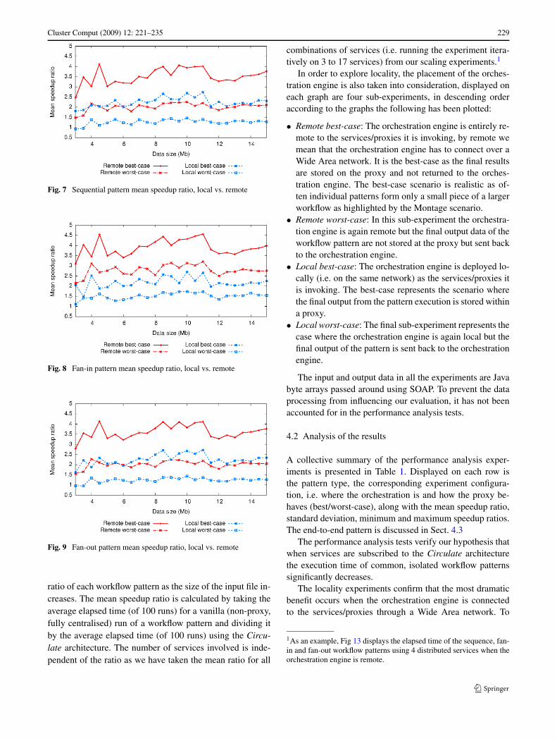
Fig. 7 Sequential pattern mean speedup ratio, local vs. remote
Fig. 8 Fan-in pattern mean speedup ratio, local vs. remote
Fig. 9 Fan-out pattern mean speedup ratio, local vs. remote
ratio of each workflow pattern as the size of the input file in-creases. The mean speedup ratio is calculated by taking theaverage elapsed time (of 100 runs) for a vanilla (non-proxy,fully centralised) run of a workflow pattern and dividing itby the average elapsed time (of 100 runs) using the Circu-late architecture. The number of services involved is inde-pendent of the ratio as we have taken the mean ratio for all
combinations of services (i.e. running the experiment itera-tively on 3 to 17 services) from our scaling experiments.1
In order to explore locality, the placement of the orches-tration engine is also taken into consideration, displayed oneach graph are four sub-experiments, in descending orderaccording to the graphs the following has been plotted:
• Remote best-case: The orchestration engine is entirely re-mote to the services/proxies it is invoking, by remote wemean that the orchestration engine has to connect over aWide Area network. It is the best-case as the final resultsare stored on the proxy and not returned to the orches-tration engine. The best-case scenario is realistic as of-ten individual patterns form only a small piece of a largerworkflow as highlighted by the Montage scenario.
• Remote worst-case: In this sub-experiment the orchestra-tion engine is again remote but the final output data of theworkflow pattern are not stored at the proxy but sent backto the orchestration engine.
• Local best-case: The orchestration engine is deployed lo-cally (i.e. on the same network) as the services/proxies itis invoking. The best-case represents the scenario wherethe final output from the pattern execution is stored withina proxy.
• Local worst-case: The final sub-experiment represents thecase where the orchestration engine is again local but thefinal output of the pattern is sent back to the orchestrationengine.
The input and output data in all the experiments are Javabyte arrays passed around using SOAP. To prevent the dataprocessing from influencing our evaluation, it has not beenaccounted for in the performance analysis tests.
4.2 Analysis of the results
A collective summary of the performance analysis exper-iments is presented in Table 1. Displayed on each row isthe pattern type, the corresponding experiment configura-tion, i.e. where the orchestration is and how the proxy be-haves (best/worst-case), along with the mean speedup ratio,standard deviation, minimum and maximum speedup ratios.The end-to-end pattern is discussed in Sect. 4.3
The performance analysis tests verify our hypothesis thatwhen services are subscribed to the Circulate architecturethe execution time of common, isolated workflow patternssignificantly decreases.
The locality experiments confirm that the most dramaticbenefit occurs when the orchestration engine is connectedto the services/proxies through a Wide Area network. To
1As an example, Fig 13 displays the elapsed time of the sequence, fan-in and fan-out workflow patterns using 4 distributed services when theorchestration engine is remote.

230 Cluster Comput (2009) 12: 221–235
Table 1 Overview of the performance analysis tests. Best-case (BC)and worst-case (WC)
Pattern Config Mean Std Dev Min Max
Sequence Local BC 2.21 0.33 1.40 2.84
Local WC 1.29 0.14 0.93 1.51
Remote BC 3.47 0.54 1.83 4.41
Remote WC 2.03 0.18 1.48 2.28
Fan-in Local BC 2.18 0.32 1.25 2.74
Local WC 1.52 0.19 0.97 1.81
Remote BC 3.88 0.53 2.23 4.97
Remote WC 2.83 0.27 2.14 3.41
Fan-out Local BC 2.25 0.34 1.19 2.88
Local WC 1.26 0.13 0.96 1.49
Remote BC 3.61 0.51 2.13 4.94
Remote WC 2.07 0.21 1.57 2.63
End-to-End Remote WC 8.18 0.94 5.58 9.86
quantify, the worst-case remote configuration, patterns sawan average performance benefit of between 2.03 and 2.83times and in the best-case remote configuration patterns anaverage performance benefit of between 3.47 and 3.88 times,with the fan-in pattern showing the largest speedup.
A surprising result of our experimentation is that evenwhen the orchestration engine is deployed on the same net-work as the services/proxies it is invoking (i.e. all communi-cation is local) there is a benefit to using the Circulate archi-tecture. In the worst-case local configuration patterns saw anaverage performance benefit of between 1.26 and 1.52 timesand in the best-case local configuration patterns an averageperformance benefit of between 2.18 and 2.25 times.
To explain the results in relation to the Circulate archi-tecture, when using a fully centralised approach the inter-mediate data have to make a costly hop back to the orches-tration engine before being again sent across the network tobe used as input to the next service in the workflow. How-ever, using the Circulate architecture, intermediate data arestored at the proxy and sent directly to the next proxy whichrequires them as input, therefore for each input:output chain,one hop is avoided. In effect, this reduces the amount of in-termediate data by 50%. This is, of course assuming that theproxy is installed as near as possible (i.e. on the same serveror network) as the service it is invoking. This benefit is validno matter where the orchestration is engine is placed, lo-cally or remotely. Our locality experiments verify that evenif workflows are orchestrated with locally deployed servicesthe Circulate architecture speeds up the overall executiontime of a workflow pattern. However, as the orchestrationengines moves further away, the hop any intermediate datahas to make increases in cost and the benefit of using the Cir-culate architecture increases accordingly. This explains why
there is an increased benefit in the remotely deployed or-chestration engine in relation to a locally deployed one. Thedifference in benefit is between 1.26 times and 1.70 times(mean remote-best–mean local-best across all patterns) inthe best-case and between 0.74 times and 1.31 times (meanremote-worst–mean local-worst across all patterns) in theworst-case.
The results (Figs. 7, 8 and 9) confirm our intuition thatthe co-plots are bounded by remote best-case (best perfor-mance) and local worst-case (worst performance) for allpatterns. The other cases lie in-between and their relativeposition depends on the specific pattern. The results alsoshow that the relative speed up is mildly sensitive to datasize. This can be explained as the speed up ratio dependson the relative amount of data sent and the relative net-work bandwidth for the local and non-local cases, both ofwhich are approximately constant. The later may have someSOAP/HTTP/TCP dependencies which likely accounts forthe small variation seen. However, the raw differential per-formance between the proxy and vanilla version does scalewith data size (see Fig. 13).
Although our experimentation is run at lower data sizesto Montage, patterns and input to output data relationshipsare maintained, this suggests that a similar performance ben-efit could be expected when scaling up the data injected intothe workflow. Further experiments not discussed in this pa-per run over the PlanetLab [21] framework confirm that theratios displayed Table 1 match those obtained from runningthe same experiments over an Internet scale network.
4.3 End-to-end execution
Sections 4.1 and 4.2 discussed workflow patterns in isola-tion, however the sequential nature of the Montage work-flow suggests that the optimisations of different workflowpatterns will have an end-to-end cumulative performancebenefit, e.g. speeding up the time to perform mConcatFitwill allow mBgModel to execute earlier, and so on. In orderto verify this hypothesis a path through the Montage work-flow was investigated, this end-to-end pattern is illustratedin Fig. 10.
This combination of patterns comprises of the followingsteps, firstly a fan-in pattern that asynchronously in parallelgathers data from 3 different services, the output of which issent to a further service which returns 20% of the input dataas output data. These data are then sent asynchronously inparallel to 3 services which each return the same volume ofoutput data as they received as input. The output data is con-catenated and sent through a further 2 services in sequence,each return 50% of the data they received as input. These in-put output data relationships mirror those found in the Mon-tage scenario.

Cluster Comput (2009) 12: 221–235 231
Fig. 10 An end-to-end workflow, with a fan-in, fan-out followed by aseries of sequential operations
Fig. 11 End-to-end pattern
The end-to-end pattern displayed in Fig. 10 is executed100 times on the Circulate architecture (using the worst-case, i.e. the final output data returns to the orchestrationengine) and 100 times on a fully centralised orchestrationengine with vanilla Web services, on both occasions the or-chestration engine is remote. In Fig. 11 the x-axis displaysthe input data size in Megabytes and the y-axis displays theratio (vanilla elapsed time divided by proxy elapsed time)in milliseconds to complete the workflow. The end-to-endexecution results in a mean speedup of 8.18 times using theproxy architecture, confirming our hypothesis that the per-formance benefit increases when isolated patterns are placedtogether to form a larger workflow. This sample end-to-endexecution demonstrates the concept, however this combina-tion pattern itself would only form a small part of larger sci-entific workflows, such as Montage.
4.4 Break even point
Invoking a proxy has an overhead in that a call is first madeto a proxy, which invokes the service on the orchestrationengines behalf, writes the result to disk and then returns areference to that data. As the previous performance analysistests demonstrate what occurs on relatively large data sizes,it is important to highlight what happens when dealing withKilobytes instead of Megabytes of data in order to determinethe break even point, i.e. when using a proxy is preferableover a vanilla service invocation.
Figure 12 displays the average time (as a ratio: vanillaelapsed time divided by proxy elapsed time) it takes to makea single invocation to a vanilla Web service and obtain the
Fig. 12 The overhead of invoking a proxy
result vs. an invocation to a proxy that invokes the service onthe orchestration engines behalf and returns a reference toits data. Results under the horizontal line indicate the vanillaapproach is optimal, results over the line show a benefit ofusing the Circulate architecture. From the results we con-clude that due to the overhead of the proxy, when dealingwith input data sizes of less than ∼100 K of data the Cir-culate architecture offers no performance benefit to vanillaWeb services. Anything over ∼100 K of data the proxy be-gins to speedup the execution time of the invocation. TheCirculate architecture is suited to larger scale workflows(such as Montage) and not workflows where very smallquantities of intermediate data are passed around betweenservices, i.e. typical scenarios in business, such as transac-tions.
5 Related work
This section discusses all related work from the literature,spanning pure choreography languages, enhancements towidely used modelling techniques, i.e. BPMN, decentralisedorchestration, data flow optimisation architectures and Gridtoolkits.
5.1 Choreography languages
There are an overwhelming number of pure orchestrationlanguages. However, relatively few targeted specifically atchoreography.
The Web Services Choreography Description Language(WS-CDL) is the proposed standard for service choreogra-phy. However, WS-CDL has met criticism [4] through theWeb services community. It is not within the scope of thispaper to provide a detailed analysis of the constructs of WS-CDL, this research has already been presented [10]. How-ever, it is useful to point out the key criticisms with the lan-guage: WS-CDL choreographies are tightly bound to spe-cific WSDL interfaces, WS-CDL has no multi-party sup-port, no formal foundation, no explicit graphical support andincomplete implementations.

232 Cluster Comput (2009) 12: 221–235
(a) Sequential pattern LOCAL orchestration engine (b) Sequential pattern REMOTE orchestration engine
(c) Fan-in LOCAL orchestration engine (d) Fan-in REMOTE orchestration engine
(e) Fan-out LOCAL orchestration engine (f) Fan-out REMOTE orchestration engine
Fig. 13 An example experiment, using 4 services, recording the aver-age time it takes for each pattern to complete as the size of the inputdata increases. The x-axis display the size of the initial input file inMegabytes (Mb) and the y-axis displays the elapsed time of the work-
flow pattern in milliseconds (ms). In (a), (c) and (e) the orchestrationengine is locally deployed, in (b), (d) and (f) the orchestration is re-motely deployed
Let’s Dance [25] is a language that supports service inter-
action modelling both from a global and local viewpoint. In
a global (or choreography) model, interactions are described
from the viewpoint of an ideal observer who oversees all in-
teractions between a set of services. Local models, on the
other hand focus on the perspective of a particular service,
capturing only those interactions that directly involve it.
BPEL4Chor [7] is a proposal for adding an additional
layer to BPEL to shift its emphasis from an orchestration
language to a complete choreography language. BPEL4Chor

Cluster Comput (2009) 12: 221–235 233
is a collection of three artifact types: participant behavior de-scriptions, participant topology and participant groundings.
5.2 Techniques in data flow optimisation
There are a limited number of research papers which haveidentified the problem of a centralised approach to serviceorchestration when dealing with data-centric workflows. Forcompleteness, this section presents an overview of a numberof architectures.
The Flow-based Infrastructure for Composing Autono-mous Services or FICAS [17] is a distributed data-flow ar-chitecture for composing software services into what the au-thors label mega-structures or workflow as it’s more com-monly known. Composition of the services in the FICASarchitecture is specified using the Compositional Languagefor Autonomous Services (CLAS), which is essentially a se-quential specification of the relationships among collaborat-ing services. This CLAS program is then translated by thebuild-time environment into a control sequence that can beexecuted by the FICAS runtime environment.
Although FICAS is an architecture for decentralised or-chestration it does not deal directly with modern standardsand is a prototype and proof of concept. The issue of Webservices integration is not addressed, nor does it discuss howthis architecture could be incorporated into an orchestrationlanguage such as the de-facto standard, BPEL. More impor-tantly FICAS is intrusive to the application code as each ap-plication that is to be deployed needs to be wrapped witha FICAS interface. In contrast, our proxy approach is moreflexible as the services themselves require no alteration anddo not even need to know that they are interacting with aproxy. Furthermore our proxy approach introduces the con-cept of passing references to data around and deals directlywith modern workflow standards.
Service Invocation Triggers [5], or simply triggers arealso a response to the problem of centralised orchestrationengines when dealing with large-scale data sets. Triggerscollect the required input data before they invoke a service,forwarding the results directly to where the data is required.For this decentralised execution to take place, a workflowmust be deconstructed into sequential fragments which con-tain neither loops nor conditionals and the data dependen-cies must be encoded within the triggers themselves.
The approach outlined by our paper and Service Invoca-tion Triggers both rely on proxies to solve the problem ofdecentralised orchestration. While Triggers address the is-sue of decentralised control, to realise these benefits theirarchitecture is based around a pure choreography model,which as discussed in this paper has many extra problemsassociated with it. Furthermore, before execution can beginthe input workflow must be deconstructed into sequentialfragments, these fragments cannot contain loops and must
be installed at a trigger; this is a rigid and limiting solutionand is a barrier to entry for the use of proxy technology. Incontrast with our proxy approach, because data referencesare passed around, nothing in the workflow has to be de-constructed or altered, which means standard orchestrationlanguages such as BPEL can be used to coordinate the prox-ies. Finally, Triggers does not deal with modern Web servicestandards.
In [19] the scalability argument made in this paper is alsoidentified. The authors propose a methodology for trans-forming the orchestration logic in BPEL into a set of in-dividual activities that coordinate themselves by passing to-kens over shared, distributed tuple spaces. The model suit-able for execution is called Executable Workshow Networks(EWFN), a Petri nets dialect.
5.3 Other relevant techniques
Triana [22] is an open-source problem solving environment.It is designed to define, process, analyse, manage, executeand monitor workflows. Triana can distribute sections of aworkflow to remote machines through a connected peer-to-peer network.
OGSA-DAI [13] is a middleware product which supportsthe exposure of data resources on to Grids. This middle-ware facilitates data streaming between local OGSA-DAIinstances.
Grid Services Flow Language (GSFL) [15] addressessome of the issues discussed in this paper in the context ofGrid services, in particular services adopt a peer-to-peer dataflow model. However, individual services have to be alteredprior to enactment, which is an invasive and custom solu-tion, something which is avoided in the Circulate architec-ture.
Graph-forwarding [11] is a technique applied to distrib-uted Objects, allowing the results of an RPC to be forwardedto the next object to invoke instead of the invoking object.This technique is similar in nature but does not addressthe issues concerning service composition through workflowtechnology.
6 Conclusions
This paper presented the Circulate architecture for execut-ing large-scale data-centric scientific workflows. Our ar-chitecture maintains the robustness and simplicity of cen-tralised orchestration, but facilitates choreography by allow-ing services to exchange data directly with one another. Us-ing Montage as a guide, a number of common workflowpatterns and input-output relationships were evaluated in aWeb services based framework. Although this paper dis-cussed the Circulate architecture in a Web services context

234 Cluster Comput (2009) 12: 221–235
(WS-Circulate), it is a general architecture and can thereforebe implemented using different technologies and integratedinto existing systems. Furthermore the Circulate architec-ture is non-invasive to the Web services themselves.
Unlike the standard orchestration model, proxies can ex-change data flow messages directly with one another avoid-ing the need to pass large quantities of intermediate datathrough a centralised server. The results indicate that sub-stantial reduction in communication overhead results in aperformance benefit of between 2.03 and 3.88 times. Theadvantage of using the Circulate architecture increases ifisolated patterns are used in combination with another, theend-to-end pattern demonstrates an 8 fold performance ben-efit.
Future directions include evaluating the benefits of ourapproach within other workflow frameworks and in othernetwork environments (e.g. wide-area, mobile) to assess theimpact in different contexts. The analysis of additional ap-plications to identify and evaluate other end-to-end work-flow patterns is also planned. Circulate opens up a rich set ofadditional optimisations with respect to proxy deploymentwhich will be evaluated in future work.
Acknowledgements Professor Daniel Katz from Louisiana StateUniversity provided detailed information about the structure and op-eration of Montage that was central to this paper.
References
1. Abu-Ghazaleh, N., Lewis, M.J., Govindaraju, M.: Differential se-rialization for optimized SOAP performance. In: Proceedings ofHPDC, June 2004
2. Apache Axis: http://ws.apache.org/axis (2008). Accessed 16 De-cember 2008
3. Barker, A., van Hemert, J.: Scientific workflow: a survey and re-search directions. In: Wyrzykowski, R., et al. (eds.) Seventh In-ternational Conference on Parallel Processing and Applied Math-ematics, Revised Selected Papers. LNCS, vol. 4967, pp. 746–753.Springer, Berlin (2008)
4. Barros, A., Dumas, M., Oaks, P.: A critical overview of theWeb services choreography description language (WS-CDL). BP-Trends Newsletter 3 (2005)
5. Binder, W., Constantinescu, I., Faltings, B.: Decentralized orches-tration of composite Web services. In: Proceedings of the Interna-tional Conference on Web Services, ICWS’06, pp. 869–876. IEEEComput. Soc., Los Alamitos (2006)
6. Chiu, K., Govindaraju, M., Bramley, R.: Investigating the limits ofSOAP performance for scientic computing. In: Proccesings of the11th International Symposium on High Performance DistributingComputing (HPDC), July 2002
7. Decker, G., Kopp, O., Leymann, F., Weske, M.: BPEL4Chor: ex-tending BPEL for modeling choreographies. In: Proceedings ofthe IEEE 2007 International Conference on Web Services (ICWS2007), pp. 296–303 (2007)
8. Deelman, E., Singh, G., Su, M.-H., Blythe, J., Gil, A., Kesselman,C., Mehta, G., Vahi, K., Berriman, G.B., Good, J., Laity, A., Ja-cob, J.C., Katz, D.S.: Pegasus: a framework for mapping complexscientific workflows onto distributed systems. Sci. Programm. J.13(3), 219–237 (2005)
9. Devaram, K., Andresen, D.: Differential serialization for opti-mized SOAP performance. In: Proceedings of PDCS, November2003
10. Fredlund, L.: Implementing WS-CDL. In: Proceedings of theSecond Spanish Workshop on Web Technologies (JSWEB 2006)(2006)
11. Grimshaw, A.S., Weissman, J.B., Strayer, W.T.: Portable run-timesupport for dynamic object-oriented parallel processing. ACMTrans. Comput. Syst. 14(2), 137–170 (1996)
12. Jacob, J.C., Katz, D.S., et. al.: The Montage architecture for grid-enabled science processing of large, distributed datasets. In: Pro-ceedings of the Earth Science Technology Conference, June 2004
13. Karasavvas, K., Antonioletti, M., Atkinson, M., Hong, N.C., Sug-den, T., Hume, A., Jackson, M., Krause, A., Palansuriya, C.: In-troduction to OGSA-DAI Services. LNCS, vol. 3458, pp. 1–12.Springer, Berlin (2005)
14. Kavantzas, N., Burdett, D., Ritzinger, G., Lafon, Y.: Web serviceschoreography description language (WS-CDL) Version 1.0. W3CCandidate Recommendation (2005)
15. Krishnan, S., Wagstrom, P., von Laszewski, G.: GSFL: a workflowframework for grid services. Technical Report, Argonne NationalLaboratory (2002)
16. Liu, D., Law, K.H., Wiederhold, G.: Analysis of integration mod-els of service composition. In: Proceedings of Third InternationalWorkshop on Software and Performance, pp. 158–165. ACM,New York (2002)
17. Liu, D., Law, K.H., Wiederhold, G.: Data-flow distribution in FI-CAS service composition infrastructure. In: Proceedings of the15th International Conference on Parallel and Distributed Com-puting Systems (2002)
18. Ludascher, B., et al.: Scientific workflow management and the Ke-pler system. Concurr. Comput., Pract. Exper. 18(10), 1039–1065(2005)
19. Martin, D., Wutke, D., Leymann, F.: A novel approach to decen-tralized workflow enactment. In: EDOC ’08. 12th InternationalIEEE Conference on Enterprise Distributed Object Computing,pp. 127–136 (2008)
20. Oinn, T., Addis, M., Ferris, J., Marvin, D., Senger, M., Green-wood, M., Carver, T., Glover, K., Pocock, M.R., Wipat, A., Li, P.:Taverna: a tool for the composition and enactment of bioinformat-ics workflows. Bioinformatics 20, 3045–3054 (2004)
21. Planet Lab: http://www.planet-lab.org (2008). Accessed 16 De-cember 2008
22. Taylor, I., Shields, M., Wang, I., Philp, R.: Distributed P2Pcomputing within Triana: a galaxy visualization test case. In:17th International Parallel and Distributed Processing Symposium(IPDPS 2003), pp. 16–27. IEEE Comput. Soc., Los Alamitos(2003)
23. The OASIS Committee: Web services business process executionlanguage (WS-BPEL) Version 2.0 (2007)
24. Wassermann, B., et al.: Sedna: A BPEL-based environment forvisual scientific workflow modelling. In: Workflows for eScience–Scientific Workflows for Grids, December 2006
25. Zaha, J.M., Barros, A., Dumas, M., ter Hofstede, A.: Let’s dance: alanguage for service behavior modelling. In: Meersman, R., Tari,Z. (eds.) OTM Conferences (1). LNCS, vol. 4275, pp. 145–162.Springer, Berlin (2006)
Cluster Comput (2009) 12: 221–235 235
Adam Barker holds a Ph.D. in In-formatics from the University of Ed-inburgh, M.Sc. in Distributed Sys-tems and B.Sc. in Software Engi-neering from Newcastle University.He is currently employed as a Re-search Assistant at the Departmentof Engineering Science, at the Uni-versity of Oxford. Prior to join-ing Oxford, Adam was employedas at the National e-Science Cen-tre (NeSC), in Edinburgh. Comple-menting his academic experience,Adam has completed internships atHewlett-Packard and BAe Systems.
Adam’s primary research interests concentrate on the effective engi-neering of large-scale, distributed systems, operating in open, decen-tralised and uncertain environments. His research agenda is pursued bymodelling, evaluating and building novel architectures and algorithmsbased on sound foundations in systems research. For further informa-tion and list of publications please refer to http:www.adambarker.org.
Jon B. Weissman is a leading re-searcher in the area of Grid com-puting. His involvement dates backto the influential Legion project atthe University of Virginia during hisPh.D. He is currently an AssociateProfessor of Computer Science atthe University of Minnesota wherehe leads the Distributed Comput-ing Systems Group. His current re-search interests are in Grid comput-ing, distributed systems, high per-formance computing, resource man-agement, reliability, and e-Scienceapplications. He works primarily at
the boundary between applications and systems. He received his B.S.degree from Carnegie-Mellon University in 1984, and his M.S. andPh.D. degrees from the University of Virginia in 1989 and 1995, re-spectively, all in computer science. He is a senior member of the IEEE.As well as being a Visitor at the Institute, Jon has been appointed anHonorary Fellow of the College of Science and Engineering at the Uni-versity of Edinburgh.
Jano I. van Hemert has a Ph.D.in Mathematics and Physical Sci-ences from the Leiden University(2002), The Netherlands. He is aResearch Associate in the Schoolof Informatics of the University ofEdinburgh and a visiting researcherat the Human Genetics Unit in Ed-inburgh of the United Kingdom’sMedical Research Council. He is re-sponsible for leading the researchwithin the National e-Science Cen-tre.He has held research positions at theLeiden University (NL), the Vienna
University of Technology (AUT) and the National Research Institutefor Mathematics and Computer Science (NL). In 2004, he was awardedthe talented young researcher fellowship by the Netherlands Organiza-tion for Scientific Research. Many of his research projects have in-cluded partners from industry.His research output includes over fifty published papers and soft-ware on optimisation, constraint satisfaction, evolutionary computa-tion, data mining, scheduling, problem difficulty, dynamic routing,adaptive methods, Grid computing, and e-Science applications.