the characteristics and use of lead-acid cap...
TRANSCRIPT

Trans. British Cave Research Association. Vol. 1. No. 4. pp.199-214. December, 1974.
THE CHARACTERISTICS AND USE OF LEAD-ACID CAP LAMPS.by M.F. Cowiishaw
Summary
It was 1885 when the first portable rechargeable lamp was invented. The lead-acid cap lamp we know today hasevolved in the ninety years since then, and has a high capacity together with many other advantages.
This paper describes the construction and characteristics of these lamps, and discusses possible modifications, theuse, and the maintenance of the most common types of lead-acid cap lamps.
1. IntroductionLighting is vitally necessary underground, and it is usually very important to ensure that there are
no failures on a caving trip, and that the lamp used is as efficient as possible — both for safety and for goodmorale.
Despite this, cap lamps of all types are often sadly abused, and the literature available in cavingmagazines is often inadequate, and sometimes contradictory.
Inevitably the standard and types of lamps used by cavers is dictated by and lags behind those usedcommercially. Hence the change over from alkali to lead-acid lamps by the NCB is now being followed bycavers. It seems likely that lead-acid lamps will be the main form of portable rechargeable lighting usedunderground for some time to come, despite the competition from more modern (and more expensive) types.
The lead-acid battery has many advantages over other rechargeable batteries (Neill: 1965), the mostimportant for cavers being: fairly high power to weight ratio; low cost; high electrical efficiency(Important where lamps are being recharged from vehicle batteries, for example); flat discharge voltagecharacteristics; simple self-service charging capability; and finally, the electrolyte is far less dangerous thanthat used in alkali batteries, although the acid will affect the strength of nylon equipment. On the otherhand, lead-acid batteries are perhaps more susceptible to incorrect charging than alkali types, though if theright method is used overcharging cannot occur and reliable performance should be obtained.
This paper describes in detail most aspects of the use and care of lead-acid lamps, and I hope willclear up many of the misunderstandings that exist concerning these lamps. In addition a small amount oftheory is included, as is a discussion on some possible modifications.
2. Brief HistoryThe principle of the lead-acid rechargeable accumulator was first applied by a german physicist
named Sinsteden in 1854. His simple cell was greatly improved to give greater capacity, first by Plante* in1960, and also by Faure in 1881. It was Faure" who developed the pasted plate from which modernnegative plates have evolved (Smith: 1971). Shortly after this, in 1885, J.W. Swan patented the firstrechargeable lead-acid hand lamp — this weighed about 4.5 Kg, and incorporated a bulls-eye lens.
In 1912 the increasing demand for electric lighting underground led to a prize being offered forthe best design (Barnard: 1936). The most successful entry was a Ceag 2 volt lead-acid lamp, though therewas no outright winner. However, two volt bulbs are inherently inefficient (as the short filament lengthimplies that a high percentage of the power available is dissipated as heat from the filament supports), andso it became obvious that four volt lamps should be designed.
The first widely used became available in about 1930 - t h i s weighed over4 Kg, and used a 1 AmpArgon-filled bulb which gave a light output of 36 lumens. In 1936 the Krypton-filled bulb was introduced,giving as much as 20 percent more light than argon filled types.
The Oldham 'Wheat' cap lamp was launched in the 1930s, and was very similar in looks to the hardrubber-cased lamps we know today. Successive models of Oldham batteries have become available sincethe war, the types most commonly used by cavers now being models Y and R. The most recent Oldhambattery to be introduced is the model T, which probably represents the state-of-the-art as far as batteriesfor miners' lamps are concerned. It is hoped that these will soon make their appearance on the cavingscene.
The well known 'Exide Triclad' first made its appearance nearly twenty years ago, and is alsowidely used, being interchangeable with Oldham types. It is usually part of the Ceag CgL2 lamp.
Modern lamps have a capacity of over 10 Amp-hours, weigh less than 2.5 Kg, and are extremelyreliable if correctly treated.
Note on definitions
The terms describing lighting sets and their constituent parts are often very loosely applied in caving circles.The following definitions are used for the purpose of this paper:
Cap lamp; lamp : The complete lighting set.
Battery : The electricity storage unit, usually carried on a belt and consisting of two lead-acid cells.
Cell : One lead-acid unit consisting of positive and negative plates, and nominally two volts.
Headset : The part that normally attaches to the helmet.
199
3. THE LEAD-ACID BATTERY
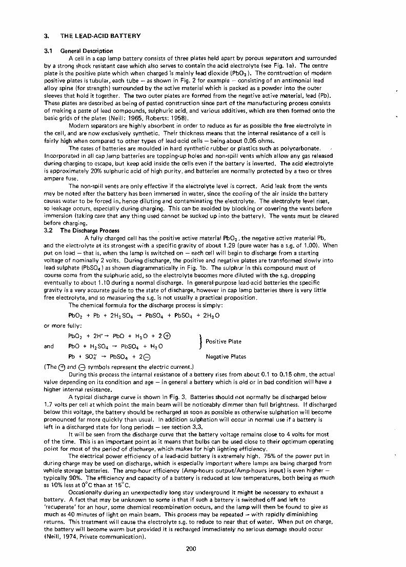
3.1 General DescriptionA cell in a cap lamp battery consists of three plates held apart by porous separators and surrounded
by a strong shock resistant case which also serves to contain the acid electrolyte (see Fig. 1a). The centreplate is the positive plate which when charged is mainly lead dioxide (PbO2 ). The construction of modernpositive plates is tubular, each tube — as shown in Fig. 2 for example — consisting of an antimonial leadalloy spine (for strength) surrounded by the active material which is packed as a powder into the outersleeves that hold it together. The two outer plates are formed from the negative active material, lead (Pb).These plates are described as being of pasted construction since part of the manufacturing process consistsof making a paste of lead compounds, sulphuric acid, and various additives, which are then formed onto thebasic grids of the plates (Neill: 1965, Roberts: 1958).
Modern separators are highly absorbent in order to reduce as far as possible the free electrolyte inthe cell, and are now exclusively synthetic. Their thickness means that the internal resistance of a cell isfairly high when compared to other types of lead-acid cells - being about 0.05 ohms.
The cases of batteries are moulded in hard synthetic rubber or plastics such as polycarbonate.Incorporated in all capjamp batteries are topping-up holes and non-spill vents which allow any gas releasedduring charging to escape, but keep acid inside the cells even if the battery is inverted. The acid electrolyteis approximately 20% sulphuric acid of high purity, and batteries are normally protected by a two or threeampere fuse.
The non-spill vents are only effective if the electrolyte level is correct. Acid leak from the ventsmay be noted after the battery has been immersed in water, since the cooling of the air inside the batterycauses water to be forced in, hence diluting and contaminating the electrolyte. The electrolyte level rises,so leakage occurs, especially during charging. This can be avoided by blocking or covering the vents beforeimmersion (taking care that any thing used cannot be sucked up into the battery). The vents must be clearedbefore charging.3.2 The Discharge Process
A fully charged cell has the positive active material PbO2 , the negative active material Pb,and the electrolyte at its strongest with a specific gravity of about 1.29 (pure water has a s.g. of 1.00). Whenput on load — that is, when the lamp is switched on — each cell will begin to discharge from a startingvoltage of nominally 2 volts. During discharge, the positive and negative plates are transformed slowly intolead sulphate (PbSO4) as shown diagrammatically in Fig. 1b. The sulphur in this compound must ofcourse come from the sulphuric acid, so the electrolyte becomes more diluted with the s.g. droppingeventually to about 1.10 during a normal discharge. In generalpurpose lead-acid batteries the specificgravity is a very accurate guide to the state of discharge, however in cap lamp batteries there is very littlefree electrolyte, and so measuring the s.g. is not usually a practical proposition.
The chemical formula for the discharge process is simply:
PbO2 + Pb + 2H2SO4 -• PbSO4 + PbSO4 + 2H2O
or more fully:
PbO2 + 2Hr-+ PbO + H2O + 2 © )\ Positive Plate
and PbO + H2SO4 -* PbSO4 + H2O J
Pb + SO4 -> PbSO4 + 2 © Negative Plates
(The © and © symbols represent the electric current.)During this process the internal resistance of a battery rises from about 0.1 to 0.15 ohm, the actual
value depending on its condition and age — in general a battery which is old or in bad condition will have ahigher internal resistance.
A typical discharge curve is shown in Fig. 3. Batteries should not normally be discharged below1.7 volts per cell at which point the main beam will be noticeably dimmer than full brightness. If dischargedbelow this voltage, the battery should be recharged as soon as possible as otherwise sulphation will becomepronounced far more quickly than usual. In addition sulphation will occur in normal use if a battery isleft in a discharged state for long periods — see section 3.3.
It will be seen from the discharge curve that the battery voltage remains close to 4 volts for mostof the time. This is an important point as it means that bulbs can be used close to their optimum operatingpoint for most of the period of discharge, which makes for high lighting efficiency.
The electrical power efficiency of a lead-acid battery is extremely high. 75% of the power put induring charge may be used on discharge, which is especially important where lamps are being charged fromvehicle storage batteries. The amp-hour efficiency (Amp-hours output/Amp-hours input) is even higher —typically 90%. The efficiency and capacity of a battery is reduced at low temperatures, both being as muchas 10% less at 0°C than at 15°C.
Occasionally during an unexpectedly long stay underground it might be necessary to exhaust abattery. A fact that may be unknown to some is that if such a battery is switched off and left to'recuperate' for an hour, some chemical recombination occurs, and the lamp will then be found to give asmuch as 40 minutes of light on main beam. This process may be repeated — with rapidly diminishingreturns. This treatment will cause the electrolyte s.g. to reduce to near that of water. When put on charge,the battery will become warm but provided it is recharged immediately no serious damage should occur(Neill, 1974, Private communication).
200

i
a) Fully charged cell .
+ve plate PbO_
-ve plates Pb
Electrolyte atstrongest.
c) Discharged.
All platesmaximum PbSO.4Electrolyte atits weakest.
Volts
b) Discharging.
Increasing PbSO4in all plates.
Electrolyte decreismqin strength.
d) Charging.
+ve plate increasing Pbo
-ve plates increasing Pb
Electrolyte increasingin strength.
Figure 1. Stages in the discharge/charge cycle.
3-4 V
5 10
Figure 3. A typical discharge curve.
Volts
-3-4V
f I I r 10
Figure 4. Discharge curves of a sulphated battery.
a) initial discharge curve.
b) after a reconditioning charge.
c) after a second reconditioning charge.
Volts
5-
4-
I-4 Amps<—|
|—» 0-5 Amps
Hours
OCM
Hours
0 5 10 Hours
Figure 5. Voltage curve for constant current charging.

10
Figure 2. Sectional view of the Oldham type 'R1 battery.
1) Rubber seal.2) Removable plug for topping up.3) Fuse.4) Gas vent link.5) Rubber lid with non-spill device.
6) Toughened hard rubber container.7) Negative pasted plate.8) Positive active material.9) Porous sleeves.10) Separator.
202
Finally, an increase in the capacity of a new battery of about 10-20% will be noted over the firstfew discharge/charge cycles. This is analogous to 'running in' and is quite normal.3.3 Sulphation
Lead sulphate is formed in the normal course of events during discharge. It takes up more spacethan the active material, and hence the porosity of the plates is reduced (Smith: 1971). The amount ofsulphate may become excessive due to repeated over-discharging without adequate recharging, by leavingthe battery in a discharged state for long periods, by use at higher temperatures (over 45°C), or by addingexcessive acid to the electrolyte. Should this happen, the porosity of the plates will be reduced to such adegree that the electrolyte is unable to reach the plates to the normal extent, which causes a reduction incapacity. In the extreme case the battery will not accept a charge at all and is therefore useless.
When sulphation occurs, the internal resistance rises due to the loss of porosity, and the sulphatecannot be wholly reconverted by charging in the normal manner as described in section 7.3. There isfortunately a cure for mild sulphation - a long slow charge of a constant half amp for about 30 hours willnormally cause an improvement. Fig. 4 illustrates this. Curve a shows the discharge curve of a badlysulphated battery, which also had one damaged cell. As can be seen, the discharge time (down to 3.4 volts)was about 4.3 hours. A remedial charge as described was then applied. After this the discharge time can beseen to have substantially risen to about 7.2 hours (curve/?). A further long constant current charge wasthen applied which resulted in a further improvement in the discharge time of half an hour — a smallerincrease (curve c).
The gradual tail off at the end of the curves is indicative of a damaged cell, and when the acid wasrestored to its proper strength in that cell the discharge curve regained its characteristic knee.
Hence an apparently unusable battery was restored to service.3.4 The Charging Process
A discharged battery has its plates chemically similar with a high amount of lead sulphate. Theelectrolyte is at its most dilute (Fig. 1c). The process of charging returns the plates to their original stateby passing an electrical current through the cells of the battery in the direction opposite to that of discharge.During this process the electrolute becomes progressively stronger, the positive plate is converted to PbO2,and the negative plates return to being spongy lead (Pb).
The simple chemical formula for this is:
PbSO4 + PbSO4 -> 2H2O + PbO2 + Pb + H2SO4
or more fully:
PbSO 4 + 2 Q -* Pb + S04' Negative Plates
PbSO4 + SO4 + 2 © -> Pb(SO4 )2 ")V Positive Plate
and Pb(SO4)2 + 2H2O -• PbO2 + 2H2SO4 J
As might be expected the internal resistance of the battery drops during charging as the platesregain their porosity.
When a discharged battery is taken off load, its voltage rises to 4 volts in a matter of minutes. If aconstant current of 1 amp is passed through it, the voltage will initially rise to about 4.2 volts and then risemore slowly until the battery is 80% charged and the voltage is around 4.6 volts. At this point profusegassing begins, and the voltage starts to rise sharply. If the current is now reduced to about half an amp(the 'finishing current'), gassing will almost stop, and the voltage will drop slightly but then begin to risesteeply, eventually levelling off at about 5.3 volts as shown in Fig. 5. The battery is then fully charged.
This constant current method of charging is not now used commercially as it is somewhatcumbersome since the current has to be reduced at the appropriate moment, and then be switched off whenthe battery is fully charged to prevent overcharging.
A modified constant potential (voltage) method is now used exclusively in NCB lamp rooms. Thissystem works by putting a constant 5 volts across a low value resistor and the battery which are in series.The purpose of this ballast resistor is to limit the current that flows when the battery is first put on charge.In practice this resistor is often incorporated in a moving iron ammeter which serves to indicate the chargingcurrent. The voltage drop, V, across the ballast resistor is given by:
V = 5 - (E + l.r) (3.4.1.)
where r is the resistance of the cable plus the effective internal resistance of the battery; E is the batteryvoltage if momentarily taken off charge; and I is the current that flows through the battery.
I is therefore given by:
I = 15 - 3E - 3l.r (3.4.2)
(if the ballast resistor is a third of an ohm)
or; I = 3 ( 5 - E)(1 + 3r)
E, the initial voltage of a battery, will be very close to 4 volts, and r will be about 0.2 ohms for alamp in normal condition, so the initial charging current will be 1.8 amps. In practice, the initial chargingcurrent for a discharged battery will be found to vary between 1.5 and 2.0 amps due to tolerances in thevalue of the ballast resistor etc.
203
Volts t Amps
5-
4-
3-
2-
1-
0
\
Amp-hours
-12
-8
-4
-05 10 Hours
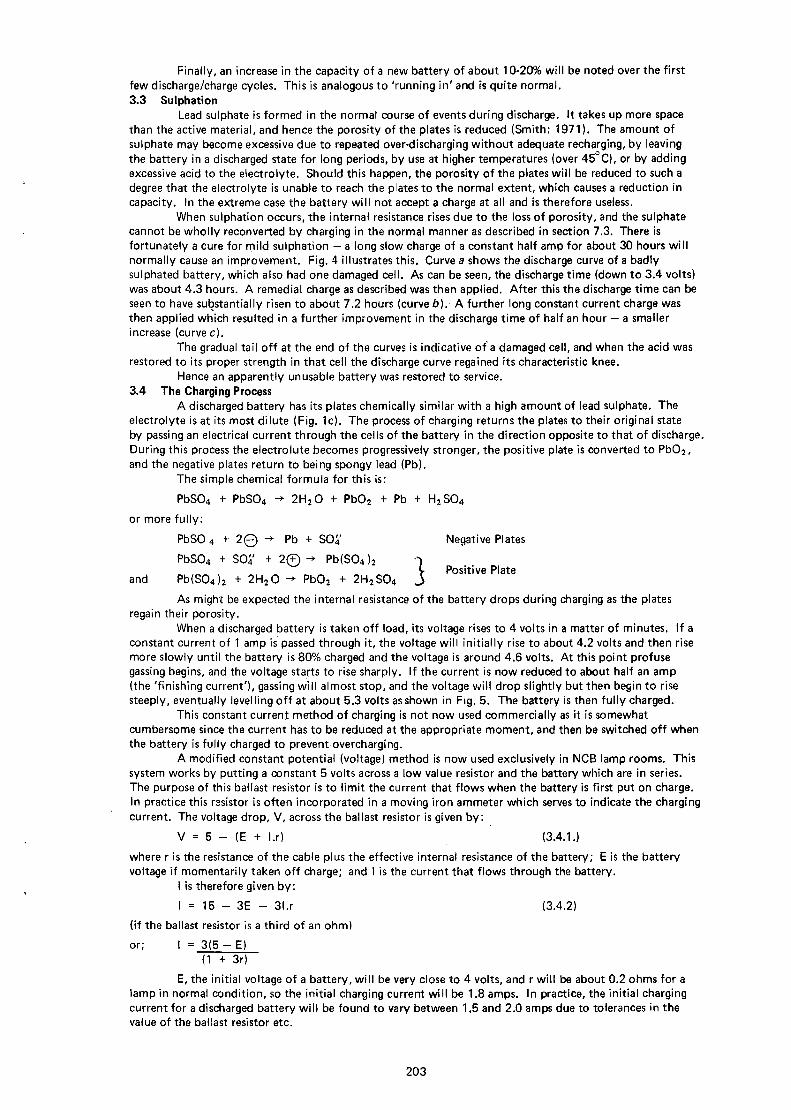
Figure 6. Modified constant potential charging.
a) Voltage curve. (E).
b) Current curve.
c) Amp-hour curve.
d) Amp-hour curve for a partially discharged battery.
10
11
14
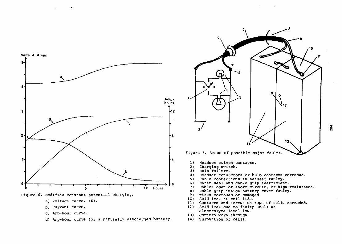
Figure 8. Areas of possible major faults.
1) Headset switch contacts.2) Charging switch.3) Bulb failure.4) Headset conductors or bulb contacts corroded.5) Cable connections in headset faulty.6) Water seal and cable grip inefficient.7) Cable: open or short circuit, or high resistance.8) Cable grip inside battery cover faulty.9) Wires corroded or damaged.
10) Acid leak at cell lids.11) Contacts and screws on tops of cells corroded.12) Acid leak due to faulty seal; or
electrolyte level low.13) Corners worn through.14) Sulphation of cells.

15
12
14
Figure 7. Sectional view of the Oldham type ' T" battery.
1) Visible electrolyte level.2) Venting and topping up aperture-3) Fuse.4) Battery terminals.5) Post seal.6) One-piece Polycarbonate lid.7) Anti-spill device.8) Integrally moulded belt loop.
9) Antimonial lead spine.10) Positive active material.11) Woven glass fibre inner sleeve.12) Perforated PVC outer sleeve.13) Absorbent separator.14) Negative plate.15) Toughened corner.16) Polycarbonate container.
205

The effective internal resistance drops to 60% of its original value during charging, and E rises to5 volts. The voltage/time curve is shown in Fig. 6a, and so the charging current curve is as shown in Fig. 6b.It will be seen that when the voltage has risen to nearly 5 volts — that is, when the battery is fully charged —the current, I, will have dropped to about 100 milliamps. A battery can take this current for one or twoweeks (A.G. Neill: 1974; Private communication) so there is evidently very little chance of overcharging asa lamp can be left on charge for several days.
It is when other methods of charging are used that damage can occur. The dangers are firstlyoverheating, caused by charging at too high a current; and secondly overcharging, which could cause thepositive plate to shed active material, hence eventually reducing the life of the battery. The first of thesemay be avoided by ensuring that the charging current is always kept below 2.5 amps. Overcharging canbe avoided either by using the recommended constant potential charging method, or, if another methodhas to be used due to force of circumstances, the charging current should be kept low enough to preventexcessive gassing, which is audible.
Excessive gassing will occur whenever too high a current is passed through a part charged battery.It takes the form of hydrogen and oxygen which is emitted from the plates at high velocity — andtherefore tends to take some active material with the bubbles. The highest current that should be passedthrough a two cell battery of voltage E while on charge is given by the formula:
Imax = 8 . 5 - 1.5E (3.4.3)
This is in effect the formula for a taper charge from 2.5 amps down to 1 amp. This can be utilised to givea fast emergency charge to a battery — see section 7.3.
It is important when charging a battery to know how much time is required to recharge itcompletely. While it is impossible to specify exact figures, as individual batteries can vary so much withage and condition, there are some general rules. The first point is that the amp-hour efficiency of lead-acidbatteries is very high, viz. about 90%. This means that if a battery is discharged for ten hours at one amp,that is, for ten amp-hours, then about eleven amp-hours will be needed to recharge it.
Secondly, most of the recharging is done in the first part of the charging process when the batteryvoltage is still fairly low. For example, about 85% of the charge is restored within 70% of the chargingtime.
Thirdly, charging time will be increased during cold weather, being about 10% longer at freezingpoint than at 10°C.
Lastly, with constant potential charging, for a given state of discharge the charging time is verynearly inversely proportional to the starting current, which is the current that flows a few minutes after thelamp is put on charge.
A mathematical approximation for the charging current during constant potential charging hasbeen determined empirically and was found to be given by:
l(t) = Isf 1 - 0.9t + 0.2 sin 27rt \ (3.4.4)
where Is is the starting current; t is the time from the beginning of charge; and T is the total time requiredfor the charge. Units are amps and hours.
T and Is are nearly inversely proportional, as stated above, the relationship being approximately:
T.ls = 2Ah (3.4.5)1.1
where Ah is the number of .amp-hours required to recharge the battery. The main formula (3.4.4) is mostaccurate when the battery is initially fully discharged, and a typical value of Ar in this situation is 11, soT.ls = 20. From this the charging time for a given starting current may be calculated. For instance, forIs = 1.8 amps, the charging time will be 11 hours.
The formula to find Aft) , the amp-hours restored to the battery after t hours on charge, may befound by integrating equation (3.4.4) as the area under the current curve up to a given time t is equal tothe amp-hours restored in that time. This gives:
Aft) = o p I(t).dt = Is ( o j t 1.dt -I0J3 o ^ t . d t +0 .2 Q [ * sin27rt \(3.4.6)
= Is ft - 0 . 9 t 2 - 0.2/cos27rt -
This curve is shown for a value of T = 11 in Fig. 6c. It will be noted that at the end of the charging period11 amp-hours have been restored to the battery, as specified. It will also be seen that the main bulk (92%)of the charging is done during the first 70% of the charging period. This implies that even if the full timeis not available for charging, the battery can often be almost fully recharged.
When only a few amp-hours need to be restored to the battery, the (cos0 - 1) term in formula(3.4.7) becomes less important, and a reasonable approximation to the amp-hour/time curve can be madeby ignoring it altogether. If in addition we substitute for T from (3.4.5), we get:
Aft) = t.ls / 1 - t.ls \ (3.4.8)
which may be used to draw the curve or to calculate the percentage restored in a given time. A typical curveis shown in Fig. 6d, for Ah = 4 hours. Is would be about 1.5 amps.
206

Finally, when a battery is taken off charge, its voltage will be nearly 5 volts. This implies that ifthe lamp is switched on immediately, it will be overrun by 25% which could lead to a premature failure.!n practice, a lamp is normally left for a few hours before use, and so the voltage will have returned to itsnormal value of about 4 volts.3.5 Types of Battery
There are two basic types of battery at present in use by cavers. These are the Oldham type, beingmainly models Y; YR; and R, the latter perhaps being the most common; and the Exide Triclad, mainlytype F2. The Oldham model T has not yet reached the caving scene in significant numbers, but adescription is included here for completeness.
The Oldham hard rubber-cased models are all very similar in appearance, though as might beexpected, the more recent the model, the more improvements that are incorporated, and the higher thecapacity.
The model R (Fig. 2) is the best of these types available, and is very robust. The terminals on thebattery are brass inserts, and there are no external and comparatively fragile vent paths such as areincorporated in the earlier model Y. The negative terminal on each cell is identified by a small pillarbeside the screw hole.
Older models are usually just as reliable as the model R; the most common problem occurring withage (after abraded corners) being acid leak from the top beside the terminals. Once acid has seepedbetween the pitch and the lid, it is very difficult to stop. Pitch will only form an efficient seal against thehard rubber if all traces of the acid are removed first. Possibly the best way to do this is to use a pencil-flame blow-torch (see section 7.5).
The capacity of a battery decreases with age and use, and as old models would originally have hadless capacity than modern types, this implies that such batteries would not be expected to give long dis-charge times now. Despite this I have seen a 17 year old model W, whose owner assured me that it stillgave eight hours of light (so the discharge time was probably about 6.5 hours) — this says something forthe quality of the battery.
All the Oldham types mentioned above include 2 Amp fuses which are mounted between the cells.These are often replaced with wire by cavers (see section 6).
The Ceag CgL lamp incorporated a fairly standard type of battery which has now been changed tothe Exide Triclad battery. This was first used in the Patterson SSI lamp (recognisable by the jack-plugcharging socket on the battery cover), and is now widely used in the Ceag CgL2 lamp.
This battery is outwardly similar to the Oldham batteries, the most obvious differencef other thanthe name on the front) being the filler plug and venting system. The plug itself Is larger on the Exidebattery, and the gas vents come out under the Plug as the holes in the plug form part of the venting system.
The other external difference is the general configuration of the battery top. The fuse is in effectin one of the leads from the battery, and the inter-cell connection is an integral part of the battery. Animportant difference from the Oldham types is the polarity of the terminals. On Oldham batteries, positiveis on the right; on Exide batteries, positive is on the left when viewed from the front.
Exide batteries have extremely sensible extra thick bottom corners — an important point forcavers whose batteries are exposed to a great deal of very abrasive wear.
The internal construction of the Exide battery is similar to the Oldham types, the main differencebeing the multiple separators and envelopes. Unfortunately the sectional view, which shows this well, is nolonger available.
The Oldham model T battery (see Fig. 7) rectifies virtually all the disadvantages inherent in earliermodels, and seems to represent a major breakthrough in battery design.
The main innovations are:Polycarbonate case and one piece lid;Integrally moulded loops for belts;Transparent panels on each cell which allow immediate inspection of electrolyte level, and include dualfunction apertures for topping up and venting.
These points make for a very easily maintained battery, which should stand up well to cavingconditions.
All standard covers fit these batteries, and as is normal with Oldham types, the fuse is mountedbetween the cells.
All types of batteries have similar electrical characteristics, and may be charged on the sameequipment. They are in effect fully interchangeable.
4. HEADSETS
4.1 GeneralThe headsets used on modern lead-acid lamps incorporate without exception the Oldham type
charging contacts and switch. However, some cavers use headsets 'cannibalised' from old alkali lamps, soI shall briefly describe some of these first.
The simplest and hence most robust type is the one bulb headset such as the old Edison. This issmall and light, if equipped with a plastic bezel. It does not have the (mainly psychological) advantage of areserve bulb, and no switch is incorporated. If a low profile switch is mounted on to the battery cover (aslider switch is ideal), the headset can be very useful as it is so small.
207

There are many two bulb types designed for alkali lamps. These include both Nife and Ceagheadsets. Many Nife types have the unique one-piece perspex cover. This when new can allow a higherlight output (Roberts: 1958) but becomes quickly scratched in use. The Ceag type has a very robustswitch worked by a cam action, but is deeper and heavier than the modern headsets designed for lead-acidlamps. However, this type does have a very deep parabolic reflector that can be polished to give a superbspot beam (see the next section).
All the types mentioned so far do not include charging contacts, and so either the battery cover orthe headset must be dismantled in order to charge the battery. All modern headsets include contacts and aswitch which allow the battery to be charged through the headset without dismantling. The purpose of theswitch is to avoid the possibility of the battery befng accidental^ short-circuited while underground in amine (which would cause dangerous sparks); however a normal charging rack may be used to draw currentfrom the battery if desired.
Most Oldham headsets in use are type 'G' — these have proven their reliability over many years.In addition to the charging switch, there is an internal four-way wiper switch for selecting either the mainbulb or the pilot bulb, with two "off" positions. This is the most vulnerable part of the headset, shouldwater be allowed to seep in. Modern type 'G' headsets, usually recognisable by the yellow bezel ring, havea one-piece plastic reflector and main bulb holder. The purpose of this is to allow easy focussing of thebulb, since more and more spot reflectors are being used. Unfortunately the wire completing the lampcircuit is easily broken by careless handling, and also the coating on the reflectors is apparently verysusceptible to damp-so especial care must be taken with the headset seals.
Very similar to the Oldham headset is the Ceag model. This is recognisable by the cross-bar thatcarries both bulbs, and the stainless steel main bulb-holder. The pilot bulb for these is a small 'pea' bulb,so the side hole in the reflector must be enlarged if the more commonly available 0.5 amp bulb is to be used.The switch is a knife blade type which is stronger, and probably more reliable, than the Oldham switch -however an uncommonly small alien key is required to dismantle the switch for maintenance.
The clip at the back of all headsets is angled at 30° to the glass, and this point should be rememberedwhen brackets are being fixed to non-standard helmets (brackets should be vertical).
The toughened glass front should always be kept as clean as possible — especially during muddytrips — to ensure maximum light transmission. It is estimated that a 'typical' thin smear of mud willreduce the light output by about 25%, and will also destroy the shape of a spot beam.4.2 Reflectors
The subject of reflectors has always been a point of controversy; some cavers swear by spotreflectors, and others by diffuse. Whereas this is partly a matter of personal opinion, there are certainlystrong and logical arguments for both types.
Diffuse reflectors give a broad beam spread over a wide area near the wearer. They also carry lesschance of dazzle should the light be accidentally directed into the face of another caver (Roberts: 1958).Some users of diffuse reflectors claim that using a spot reflector gives them headaches; if this is so thenthey must obviously use a diffuse reflector. A diffuse beam will also be particularly useful in low orconstricted passages where it may be necessary to bend one's head away from the desired field of view.
A spot reflector can take a bit of getting used to as more head movements are required. The mainadvantage is in walking-sized passages or chambers, especially those with boulder-strewn floors, as one canlook further ahead with a spot beam, and relief on the floor shows up better when the spot is moved acrossit. Also, of course, one can better appreciate the magnitude of large passages with a far reaching spot beam.
The only conclusion that can be drawn from the above is that possibly one should choose areflector according to the trip attempted: for instance a spot beam is ideal for most of Ogof FfynnonDdu I I , but for Penyghent Pot a diffuse reflector might be the better choice.
The deep reflectors used in the Old Ceag alkali type headset are claimed by some to give a verygood spot beam. To achieve this, the reflector must be polished — if this is done (and this applied topolishing all types of reflector) precautions must be taken to inhibit tarnishing which could result in a 1*5%
'drop in light output (Roberts: 1958). Polishing is best carried out on a lathe, or by fixing the reflector toan electric drill using a sandpaper disc holder.
Modern reflectors should normally never be polished, as they have an extremely efficient vacuumdeposited surface which is coated with a special protective varnish. Further, some reflectors are notaluminium all through. The latest types, as described in the last section, are based on plastic; others arebased on brass.
If a reflector should get mud or grease on its surface, water and soap (not detergent) may be usedto remove the dirt. A badly scratched or dirty glass will also affect the light output and beam shape of alamp.
With all reflectors, changing the position of the bulb will change the light distribution pattern.The best position may be found by trial and error by moving the bulb in or out until the most satisfactoryresult is obtained. With parabolic spot reflectors, the bulb filament should be at the focus of the reflector.
A comprehensive treatment of the distribution patterns given by different reflectors is included in'Underground Lighting' (Roberts: 1958). Problems of glare are also discussed there, and elsewhere (Neill &Bell: 1972).4.3 Bulbs
Main bulbs for use underground in coal mines are covered by BS535 : 1973, and cavers shouldalways use bulbs that conform to these specifications. All such bulbs are now Krypton-filled; which means
208
that about 17% more light is obtained at a given wattage, than with Argon-filled types. The reason for thisis that Krypton has a higher density and a lower specific heat than,Argon, so higher filament temperaturescan be used which in turn leads to higher efficiency.
Bulbs are normally rated at 4 volts, 1 amp; and occasionally at 3.6 volts or 0.9 amps. The meandischarge voltage of a lead-acid battery is typically 3.8 volts, hence a 4 volt bulb is being underrun for mostof the discharge period, with a mean drop in the light output of about 12% (Roberts: 1958; Cotton: 1955).There is therefore some argument for using bulbs rated at 3.6 volts if any are obtainable. As the bulb isthen being overrun by 7% on average, improved light output is obtained at the expense of a slightly highercurrent drain and reduced life (being about 60% of normal).
It is informative to consider the performance of a standard 4 volt 1 amp bulb as the voltage dropsfrom 4 volts, as occurs at the end of the discharge period. Some voltages are tabulated below for a typicalbulb.
4 volts: 1.00 amps: Normal full brightness.3.4 volts: 0.94 amps: Brightness first noticeably dimmer than normal.2.5 volts: 0.80 amps: Brightness equivalent to normal pilot bulb at full voltage.1.8 volts: 0.70 amps: Light weak but just usable.1.2 volts: 0.60 amps: Light no longer usable.
From this table it may be deduced that there is no great saving to be made by switching over to the pilotbulb once the main bulb becomes dim, since the pilot bulb would then be dimmer still, and possiblyunusable. It is far better to switch the lamp off for 30 minutes or so, and then perhaps use pilot bulb,(see section 3.2).
The specification for the life-span of main bulbs is laid down to be 200 hours continuous (BS535:1973). In practice, bulb life has been found to vary between 400 and 4500 hours of normal use (Roberts:1958; BS535: 1973). It therefore seems most improbable that a bulb would last for less than 400 hours,so the careful caver could virtually eliminate the possibility of bulb failure underground by carrying out aroutine replacement after 400 or 500 hours.
Bulb failures are caused mainly by mechanical or normal end-of-life breakage of the filament.Occasionally with older bulbs the cement holding the cap to the glass part disintegrates. If this occurs, thebulb is best replaced since it must be fairly o'd. Barnard (1936) states that filaments are strongest whenhot; a point to be borne in mind when headsets are being banged around in transit.
Modern bulbs have a filament temperature of over 2800°C, and do not give a pure white light, thecolour being similar to that of the common household mains bulb. The total light output is typically 40lumens, which may be considered to be about three candle-power. The reader is referred to 'UndergroundLighting' (Roberts: 1958) for a full discussion on photometry as applied to miners' cap lamps.
Most of the above also applies to pilot bulbs, which are rated at 4 volts, 0.46 amps (for Oldhamlamps); or 4 volts, 0.3 amps (for Ceag lamps). If a lamp is used solely on pilot bulb, the increasedefficiency due to the lower discharge rate would result in an increase in the discharge time of about 2.2 or3.5 times respectively, when compared with the normal main bulb discharge time. This might be relevantif a lamp is being used for continuous low-level illumination — at an underground camp-site, for example.
Unless damaged, pilot bulbs should last indefinitely if subjected to normal occasional use.
5. THE CABLE AND BATTERY COVERCables are almost without exception spirally wound short lay types with a central textile cord to
reduce stresses in the wiTe cores themselves. The whole is enclosed in a close fitting sheath of polychloropenewhich fills ail the gaps between the inner cores (BS4945: 1973). The cores have a low resistance (less than0.03 ohms per metre), which means that power wastage in the cable is about 1% of the power developed bythe battery during discharge.
The identification colours for the cores are:Positive: Brown (Red on old cables)Negative: Blue (Black on old cables)
The most common cause of damage to the cable occurs when it is used to pick the lamp up. Thiscan cause internal stresses close to the battery which may lead to an increase in resistance or an open circuit,especially in older cables where the centre cord might have been broken or weakened. Also, if the cablegrip is defective, the wires could be pulled off the battery terminals. The best way to test the resistance ofa cable is to switch the lamp on, and then to measure the voltage across each of the two cores. Neithershould exceed 0.1 volts, and should be less than 0.05 volts.
The length of cables is usually about 1.3 metres, but the individual caver might prefer a longer orshorter cable. Metal clips for attaching cables to the rear of helmets should be carefully inspected toensure that they cannot damage the cable. In general, nylon or similar cord is preferable to a metal clip,since high stresses may result whenever the cable is held at a sharp angle to the clip, as may occur whilecrawling.
Battery covers are all very similar in design and are interchangeable between batteries of differentmakes. They are made of stainless steel, and incorporate some form of cable grip, and a grommet wherethe cable leaves the cover. Covers are held on by a simple locking device with a special screw that is sealedwith wax when the lamp is used in mines. This seal is usually removed, and a normal slot cut in the screwwhen the lamp is used for caving (see section 6.).
209
The Oldham cover has a very much better cable grip than the Ceag type, at the expense ofincreased height. In addition, since the cable leaves the cover in the middle, the cable is far more protectedagainst abrasion than with other types of cover.
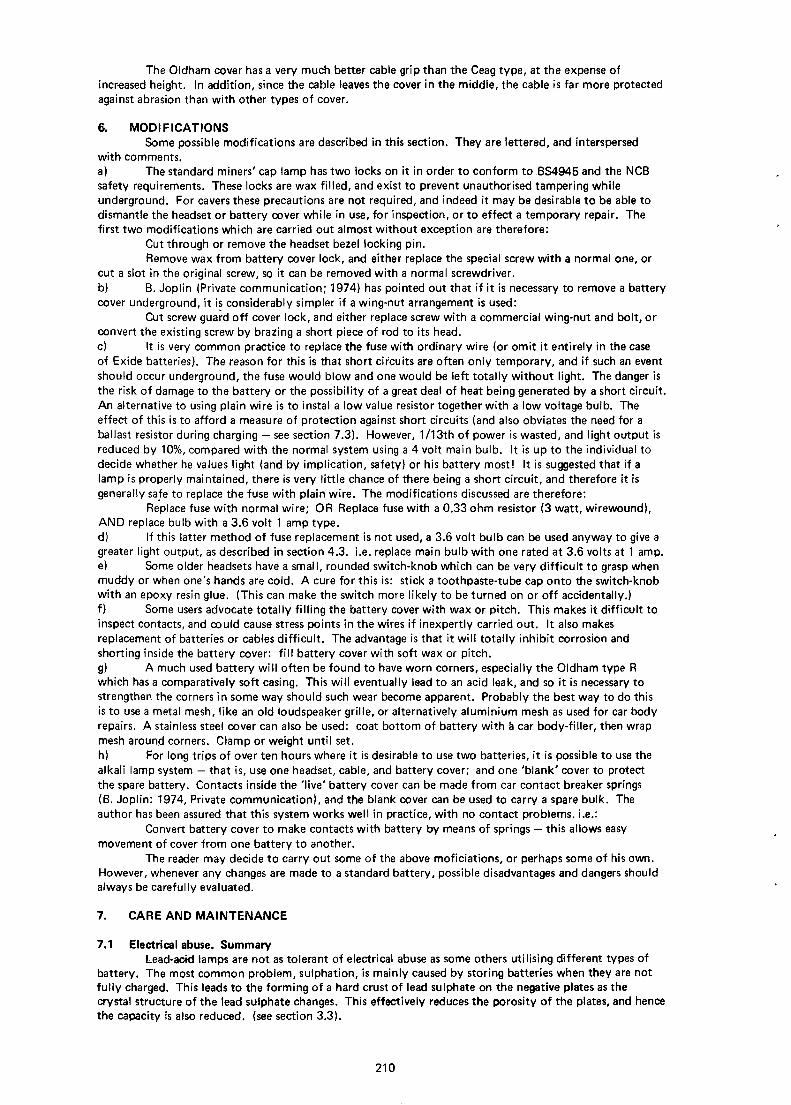
6. MODIFICATIONSSome possible modifications are described in this section. They are lettered, and interspersed
with comments.a) The standard miners' cap lamp has two locks on it in order to conform to BS4945 and the NCBsafety requirements. These locks are wax filled, and exist to prevent unauthorised tampering whileunderground. For cavers these precautions are not required, and indeed it may be desirable to be able todismantle the headset or battery cover while in use, for inspection, or to effect a temporary repair. Thefirst two modifications which are carried out almost without exception are therefore:
Cut through or remove the headset bezel locking pin.Remove wax from battery cover lock, and either replace the special screw with a normal one, or
cut a slot in the original screw, so it can be removed with a normal screwdriver.b) B. Joplin (Private communication; 1974) has pointed out that if it is necessary to remove a batterycover underground, it is considerably simpler if a wing-nut arrangement is used:
Cut screw guard off cover lock, and either replace screw with a commercial wing-nut and bolt, orconvert the existing screw by brazing a short piece of rod to its head.c) It is very common practice to replace the fuse with ordinary wire (or omit it entirely in the caseof Exide batteries). The reason for this is that short circuits are often only temporary, and if such an eventshould occur underground, the fuse would blow and one would be left totally without light. The danger isthe risk of damage to the battery or the possibility of a great deal of heat being generated by a short circuit.An alternative to using plain wire is to instal a low value resistor together with a low voltage bulb. Theeffect of this is to afford a measure of protection against short circuits (and also obviates the need for aballast resistor during charging — see section 7.3). However, 1 /13th of power is wasted, and light output isreduced by 10%, compared with the normal system using a 4 volt main bulb. It is up to the individual todecide whether he values light (and by implication, safety) or his battery most! It is suggested that if alamp is properly maintained, there is very little chance of there being a short circuit, and therefore it isgenerally safe to replace the fuse with plain wire. The modifications discussed are therefore:
Replace fuse with normal wire; OR Replace fuse with a 0.33 ohm resistor (3 watt, wirewound),AND replace bulb with a 3.6 volt 1 amp type.d) If this latter method of fuse replacement is not used, a 3.6 volt bulb can be used anyway to give agreater light output, as described in section 4.3. i.e. replace main bulb with one rated at 3.6 volts at 1 amp.e) Some older headsets have a small, rounded switch-knob which can be very difficult to grasp whenmuddy or when one's hands are cold. A cure for this is: stick a toothpaste-tube cap onto the switch-knobwith an epoxy resin glue. (This can make the switch more likely to be turned on or off accidentally.)f) Some users advocate totally filling the battery cover with wax or pitch. This makes it difficult toinspect contacts, and could cause stress points in the wires if inexpertly carried out. It also makesreplacement of batteries or cables difficult. The advantage is that it will totally inhibit corrosion andshorting inside the battery cover: fill battery cover with soft wax or pitch.g) A much used battery will often be found to have worn corners, especially the Oldham type Rwhich has a comparatively soft casing. This will eventually lead to an acid leak, and so it is necessary tostrengthen the corners in some way should such wear become apparent. Probably the best way to do thisis to use a metal mesh, like an old loudspeaker grille, or alternatively aluminium mesh as used for car bodyrepairs. A stainless steel cover can also be used: coat bottom of battery with a car body-filler, then wrapmesh around corners. Clamp or weight until set.h) For long trips of over ten hours where it is desirable to use two batteries, it is possible to use thealkali iamp system - that is, use one headset, cable, and battery cover; and one 'blank' cover to protectthe spare battery. Contacts inside the 'live' battery cover can be made from car contact breaker springs(B. Joplin: 1974, Private communication), and the blank cover can be used to carry a spare bulk. Theauthor has been assured that this system works well in practice, with no contact problems, i.e.:
Convert battery cover to make contacts with battery by means of springs — this allows easymovement of cover from one battery to another.
The reader may decide to carry out some of the above moficiations, or perhaps some of his own.However, whenever any changes are made to a standard battery, possible disadvantages and dangers shouldalways be carefully evaluated.
7. CARE AND MAINTENANCE
7.1 Electrical abuse. SummaryLead-acid lamps are not as tolerant of electrical abuse as some others utilising different types of
battery. The most common problem, sulphation, is mainly caused by storing batteries when they are notfully charged. This leads to the forming of a hard crust of lead sulphate on the negative plates as thecrystal structure of the lead sulphate changes. This effectively reduces the porosity of the plates, and hencethe capacity is also reduced, (see section 3.3).
210
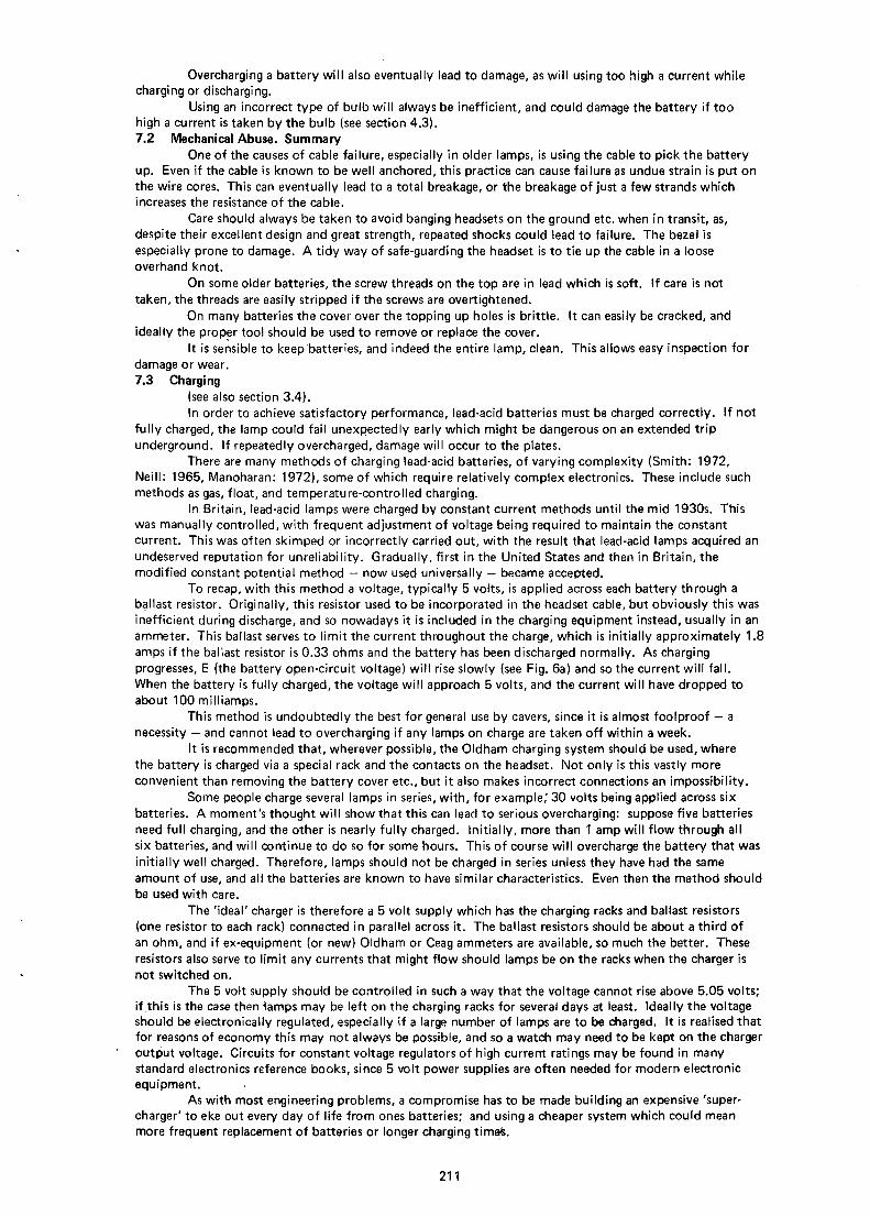
Overcharging a battery will also eventually lead to damage, as will using too high a current whilecharging or discharging.
Using an incorrect type of bulb will always be inefficient, and could damage the battery if toohigh a current is taken by the bulb (see section 4.3).7.2 Mechanical Abuse. Summary
One of the causes of cable failure, especially in older lamps, is using the cable to pick the batteryup. Even if the cable is known to be well anchored, this practice can cause failure as undue strain is put onthe wire cores. This can eventually lead to a total breakage, or the breakage of just a few strands whichincreases the resistance of the cable.
Care should always be taken to avoid banging headsets on the ground etc. when in transit, as,despite their excellent design and great strength, repeated shocks could lead to failure. The bezel isespecially prone to damage. A tidy way of safe-guarding the headset is to tie up the cable in a looseoverhand knot.
On some older batteries, the screw threads on the top are in lead which is soft. If care is nottaken, the threads are easily stripped if the screws are overtightened.
On many batteries the cover over the topping up holes is brittle. It can easily be cracked, andideally the proper tool should be used to remove or replace the cover.
It is sensible to keep batteries, and indeed the entire lamp, clean. This allows easy inspection fordamage or wear.7.3 Charging
(see also section 3.4).In order to achieve satisfactory performance, lead-acid batteries must be charged correctly. If not
fully charged, the lamp could fail unexpectedly early which might be dangerous on an extended tripunderground. If repeatedly overcharged, damage will occur to the plates.
There are many methods of charging lead-acid batteries, of varying complexity (Smith: 1972,Neill: 1965, Manoharan: 1972), some of which require relatively complex electronics. These include suchmethods as gas, float, and temperature-controlled charging.
In Britain, lead-acid lamps were charged by constant current methods until the mid 1930s. Thiswas manually controlled, with frequent adjustment of voltage being required to maintain the constantcurrent. This was often skimped or incorrectly carried out, with the result that lead-acid lamps acquired anundeserved reputation for unreliability. Gradually, first in the United States and then in Britain, themodified constant potential method — now used universally — became accepted.
To recap, with this method a voltage, typically 5 volts, is applied across each battery through aballast resistor. Originally, this resistor used to be incorporated in the headset cable, but obviously this wasinefficient during discharge, and so nowadays it is included in the charging equipment instead, usually in anammeter. This ballast serves to limit the current throughout the charge, which is initially approximately 1.8amps if the ballast resistor is 0.33 ohms and the battery has been discharged normally. As chargingprogresses, E (the battery open-circuit voltage) will rise slowly (see Fig. 6a) and so the current will fall.When the battery is fully charged, the voltage will approach 5 volts, and the current will have dropped toabout 100 milliamps.
This method is undoubtedly the best for general use by cavers, since it is almost foolproof - anecessity - and cannot lead to overcharging if any lamps on charge are taken off within a week.
It is recommended that, wherever possible, the Oldham charging system should be used, wherethe battery is charged via a special rack and the contacts on the headset. Not only is this vastly moreconvenient than removing the battery cover etc., but it also makes incorrect connections an impossibility.
Some people charge several lamps in series, with, for example/ 30 volts being applied across sixbatteries. A moment's thought will show that this can lead to serious overcharging: suppose five batteriesneed full charging, and the other is nearly fully charged. Initially, more than 1 amp will flow through allsix batteries, and will continue to do so for some hours. This of course will overcharge the battery that wasinitially well charged. Therefore, lamps should not be charged in series unless they have had the sameamount of use, and all the batteries are known to have similar characteristics. Even then the method shouldbe used with care.
The 'ideal' charger is therefore a 5 volt supply which has the charging racks and ballast resistors(one resistor to each rack) connected in parallel across it. The ballast resistors should be about a third ofan ohm, and if ex-equipment (or new) Oldham or Ceag ammeters are available, so much the better. Theseresistors also serve to limit any currents that might flow should lamps be on the racks when the charger isnot switched on.
The 5 volt supply should be controlled in such a way that the voltage cannot rise above 5.05 volts;if this is the case then lamps may be left on the charging racks for several days at least. Ideally the voltageshould be electronically regulated, especially if a large number of lamps are to be charged. It is realised thatfor reasons of economy this may not always be possible, and so a watch may need to be kept on the chargeroutput voltage. Circuits for constant voltage regulators of high current ratings may be found in manystandard electronics reference books, since 5 volt power supplies are often needed for modern electronicequipment.
As with most engineering problems, a compromise has to be made building an expensive 'super-charger' to eke out every day of life from ones batteries; and using a cheaper system which could meanmore frequent replacement of batteries or longer charging timeHs.
211
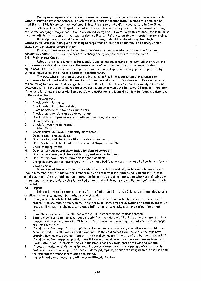
During an emergency of some kind, it may be necessary to charge lamps as fast as is practicablewithout causing permanent damage. To achieve this, a charge tapering from 2.5 amps to 1 amp can beused (Neill: 1974; Private communication). This will recharge a fully discharged battery in 5 to 6 hours,and the battery will be 80% charged in about 4.5 hours. This taper charge can easily be carried out usingthe normal charging arrangement but with a supplied voltage of 5.4 volts. With this method, the lamp mustbe taken off charge as soon as its voltage has risen to 5 volts. Failure to do this will result in overcharging.
If a lamp is not expected to be used for some time, it should be stored away from hightemperatures, and should be given a discharge/charge cycle at least once a month. The battery shouldalways be fully charged before storage.
Finally, it must be remembered that all mains-run charging equipment should be fused andadequately earthed — as it is all too easy for a charger being used by cavers to become damp.7.4 Maintenance Checks
Using an unreliable lamp is as irresponsible and dangerous as using an unsafe ladder or rope, andso the same care should be taken over the maintenance of lamps as over the maintenance of otherequipment. The chances of a lamp failing in normal use can be kept down to negligible proportions byusing common sense and a logical approach to maintenance.
The areas where most faults occur are indicated in Fig. 8. It is suggested that a scheme ofmaintenance be followed which will detect all of these potential faults. For those who like a set scheme,the following two part method is suggested — the first part, of simple checks, can be quickly carried outbetween trips, and the second more exhaustive part could be carried out after every 25 trips (or more oftenif the lamp is not used regularly). Some possible remedies for any faults that might be found are describedin the next section.
Between trips:A Check both bulbs light.B Check both bulbs switch reliably.C Examine battery case for holes and cracks.D Check battery for signs of acid or corrosion.E Check cable is gripped securely at both ends and is not damaged.F Clean headset glass.G Check for water inside headset.
After 25 trips:H Check electrolyte level. (Preferably more often.)I Open headset, and check seals.J Open headset, and check condition of cable in headset.K Open headset, and check bulb contacts, metal strips, and switch.L Check charging switch.M Open battery cover, and check inside for signs of corrosion.N Open battery cover, and check cable, grip, and wires to terminals.O Open battery cover, check terminals for good contacts.P Charge battery, and test discharge time — it is not a bad idea to keep a record of all such tests for each
battery owned.Where a set of lamps is owned by a club rather than by individuals, each caver who uses a lamp
should remember that it is his (or her) responsibility to check that the lamp being used appears to be ingood condition. Also, should any fault appear during use, it should be reported to whoever maintains thelamps; and the lamp should be clearly labelled to ensure that it is not accidentally used before the fault iscorrected.
7.5 RepairsThis section describes some remedies for the faults listed in section 7.4. It is not intended to be a
detailed maintenance manual, but rather a general guide.A If only one bulb fails to light, either the bulb is faulty, or more probably the switch is corroded or
broken. Replace bulb or faulty part. If neither bulb lights, first check switch and contacts inside theheadset. If no fault is obvious, carry out a full maintenance check, as a more serious fault mustexist.
B If switch is unreliable, dismantle and clean it. If no improvement, replace contacts.C Battery may have to be replaced, but car body filler may do the trick. First turn the battery so hole
is uppermost, wash and leave for 24 hours. Then remove all remaining traces of acid with sandpaperor a small blowtorch.
D If acid comes from top of battery, pitch can be used to reseal the leak, after all traces of acid havebeen removed — ideally with a small blowtorch. If the acid comes from the vents, the cells haveprobably been over topped-up — check. If the acid comes from the case of the battery, treat as in C.If acid comes from topping-up seal, smear lightly with vaseline — note that care must be taken withExide batteries not to block the holes in the plug, since they form part of the venting system.
E If loose at headset end, tighten grip-nut. If loose at battery cover, the gripping device is probablybroken and needs replacing. If the cable is damaged, replace, or cut off damaged area if near end andthe resultant shortened length can be tolerated.
F If glass is badly scratched, light will be over-diffused. Replace.
212

G Dismantle headset. Check switch seal, cable seal, gasket ring. Vaseline on the latter may help.Replace faulty seals. Clean and dry every part of the headset before reassembly.
H With all types of batteries, the electrolyte should just cover the plates. Any higher and the non-spillsystem will not work correctly; much lower and eventually the capacity of the battery will bereduced. If a great deal of topping up is needed, check for leaks or a fault in the battery chargercausing overcharging.
I Replace if damaged. See also G.J AsE.K If not obviously in good condition; dismantle and clean all parts. Replace any suspect parts. All
parts should be lightly smeared with vaseline before reassembly.L Dismantle switch and clean parts. If any seem very worn, replace. Do not apply any lubricant or
grease, as this can trap grit and form an abrasive paste.M Acid corrosion implies acid leak. Clean affected parts, and replace any severely damaged (including
cable). Repair acid leak - see D.N Cable should be checked for short circuit, open circuit, or high resistance due to corrosion. If any of
these are found, it is best to replace cable. If grip is inefficient, it will probably need to be replaced.0 All terminals should be clean and virtually free from corrosion. Undo all screws, clean contact areas,
smear with vaseline and replace. Excessive corrosion is probably caused by an acid leak. See M.P Charge battery fully (see section 7.3). Allow to stand for about an hour, then switch on main bulb.
Leave on continuously and time until voltage across battery falls to 3.4 volts. This time is the dischargetime of the battery, and should be at least 7 hours. The discharge time will drop with age, but it ispossible that sulphation has occurred (see section 3.3). If this is suspected, a reconditioning charge ofa third to one half of an amp should be applied for about 30 hours. This will normally result in anincrease of discharge time. If it does not, the battery is either damaged beyond repair by severesulphation or other abuse, or has reached the end of its life. In any case, before a battery is discardedfor giving a low discharge time, a reconditioning charge should be tried. The charger being used shouldalso be checked, as if it is faulty, then the battery may not be receiving a full charge.
In many places in the above, replacement of faulty parts is advocated. Where appropriate, suitablehome-made replacements can of course be used, though their suitability and safety should always becarefully assessed first.
8. CONCLUSIONSIn the author's opinion, the possibility of lead-acid lamp failure underground is extremely remote
ifxommon sense is used, and a few simple rules are adhered to.The maximum life should be obtained from a lamp if:
Constant Potential charging with a maximum of 5.05 volts is used;The battery is recharged as soon as possible after use;The cells are topped-up regularly;The cable grips are maintained in good condition;The interior of the headset is kept dry.
In an emergency; the following facts could be very useful:If a battery has been discharged until the light is no longer usabje, a surprising amount of light can beobtained by switching off for up to two hours so the battery can 'recuperate'. .An 80% charge can be achieved in about 4.5 hours by using a fast charge tapering from 2.5 towards 1 amp.
It is hoped that the information included in this paper will be useful to many people, and willcontribute towards the safety of any speleologist or sportsman using a lead-acid cap lamp underground.
AcknowledgementsThe author would like to thank:The Department of Electronic and Electrical Engineering at the University of Birmingham, for use of laboratory
facilities;Oldham and Son Ltd., for the photographs accompanying this paper, and for leaflets, offprints, etc.; and
especially Dr. A.G. Neill, Mining Division Manager of that firm, for answering a long list of technical questions;Ceag Ltd. and Chloride Industrial Batteries Ltd., for much useful information;H. Nailor, A. Morley and J. Neill, for critical reading of the manuscript.
Final Manuscript received 17th August, 1974 M.F. Cowlishaw,Hilston,Cleveland WalkBath.
References and selected BibliographyBarnard, T.R. 1936. Miners'safety lamps; Their construction and care. Pitman, London.BSI 197 3. BS 535: Ligh t sources for miners' portable electric lamps.
1973. BS4945: Miners' cap lamp assemblies (incorporating lead-acid type batteries).Cantonwine, C.R. 1971. Battery chargers and testers. Chilton, London.Cotton, H. (Ed.) 1955. Electrical equipment in minesEllis, B. & Bull, G. 1967. A survey of headware and lighting available for caving. Bristol Expl. Club.
Caving Report No. 5.
213

Hofman, W. 1970. Lead and Lead alloys (pp 341-356).Jones, J.A. 1973. Charging and maintenance of Oldham Lamps. Derbyshire Caving Assoc.
Newsl. 15.Manoharan, L.C. 1974. Int. J. Electronics, Vol. 36, No. 2, pp.231-238.Mantel I, C.L. 1970. Batteries and energy systems.Molloy, E. 1947. Q & A on Batteries and Battery charging. Jarrold. Norwich.Neill, A.G. 1965. The lead-acid Battery with particular reference to its use in Mining.
The mining electrical and mechanical engineer, November 1965.Neill, A.G. & Bell, W.B. 1972. Lighting in coal mines. Light and Lighting, August 1972.Roberts, A. 1958. Underground Lighting. Technical Press, London.Smith, G.W. 1972. Storage Batteries. Pitman, London.
214