the cd-rom of cx-one / cx-programmer ... -...
TRANSCRIPT


The CD-ROM of CX-One / CX-Programmer has User's Manual of the PDF file.Please read the 'Notice' and the 'Precautions' in the User's Manual before using CX-Programmer.The ‘Function Block Introduction Guide' describes the basic operation procedure to use Function Block ofCX-Programmer and hints to create user program with Function Blocks. Refer to the Help or the User'sManual of the PDF file for detailed descriptions.* You need Acrobat Reader 4.0 or grater versions in your PC to display the PDF file.

1-11-21-31-31-41-61-7
2-12-12-12-22-32-42-52-62-62-72-72-92-102-112-122-13
3-13-13-13-23-33-43-43-5
4-14-14-24-34-44-54-64-74-8
5-15-15-15-25-95-145-155-16
Appendix
ContentsChapter 1 OMRON FB Library 1. What is a Function Block? 2. An Example of a Function Block 3. Overview of the OMRON FB Library
3-1. Benefits of the OMRON FB Library3-2. Example of using the OMRON FB Library3-3. Content of the OMRON FB Library3-4. File Catalog and Where to Access the OMRON FB Library
Chapter 2 How to use the OMRON FB Library 1. Explanation of the target program
1-1. Application Specifications1-2. Specifications of the OMRON FB Part file1-3. Input program
2. Opening a new project and setting the Device Type 3. Main Window functions 4. Import the OMRON FB Part file 5. Program Creation
5-1. Enter a Normally Open Contact5-2. Entering an Instance5-3. Entering Parameters
6. Program Error Check (Compile) 7. Going Online 8. Monitoring - 1 9. Monitoring - 2 Change Parameter Current Value 10. Online Editing
Chapter 3 Customize the OMRON FB Part file 1. Explanation of target program
1-1. Changing File Specifications1-2. Changing the contents of the OMRON FB Part file
2. Copy the OMRON FB Part file 3. Add a variable to the Function Block 4. Changing the Function Block Ladder
4-1. Entering a Contact4-2. Checking Usage Status of Variables
Chapter 4 How to use the ST (Structured Text) language 1. What is the ST Language? 2. Explanation of the target program 3. Create a Function Block using ST 4. Entering Variables into Function Blocks 5. Entry of ST program 6. Entering the FB to the Ladder Program and error checking 7. Program Transfer 8. Monitoring the Function Block execution Reference: Example of an ST program using IF-THEN-ELSE-END_IF
Chapter 5 Advanced (Componentizing a Program Using FB) 1. Overview 2. How to Proceed Program Development 3. Application Example 4. How to Proceed Program Development 5. Entering FB Definition 6. Creating FB Definition Library 7. Entering Main Program 8. Debugging Main Program
Supplemental Information How to delete unused Function Block definitions Memory allocation for Function Blocks Useful Functions Appendix. Examples of ST (Structured Text)

IntroductionThis document summarizes tips for using OMRON FB Library and creating function block (FB), which are available forOmron’s SYSMAC CS1/CJ1-H/CJ1M series CPU unit (unit version 3.0 or later) and CX-Programmer Ver.5.0 or later.
New functions available on CX-Programmer Ver. 6.0Nesting of FBNesting of FBs is now available for easier use of FB as a method to structure and reuse user programs. FB can be calledfrom a ladder program structured text (ST) program that is converted to FB. Following functions are also supported for this.
Easy understanding of program structure . . . FB Instance ViewerManagement as components including called FBs . . . Saving and loading of files including called FBEasy jump to called FB . . . Mouse double-click operation on FB Instance (calling instruction)
Monitoring of FB ladderAs with main ladder program, state of FB ladder program can be monitored.
Cross reference pop-up in FB ladderAs with main ladder program, cross reference pop-up is now available in FB ladder program.Also supported now is jump to output coil from contact via space key.
Jump to ST helpYou can jump Structured Text editor through pop-up menu to a help topic to easily check syntax for ST programming.
Jump to library reference of OMRON FB LibraryYou can easily view a PDF file of library cross reference that describes specifications from a OMRON FB Libraryregistered in a project file.
Caution:Although you can use a program that contains nested FB for a CS1/CJ1-H/CJ1M series CPU unit (unit version 3.0 orlater), if you try to upload a program that contains nested FB by CX-Programmer (Ver.5.0 or older) that does not supportnesting, either you will fail to do so or you will just get one under incomplete state.If you save the file as it is, you will not be able to tell difference between the incomplete and correct programs.
[In case of CX-Programmer Ver.5.0]Following messages will be shown after upload is finished:
The PLC properties which are not supported by this version of CX-Programmer are set in the connecting target PLC.The PLC properties will not be displayed correctly. Do you wish to continue?
[In case of CX-Programmer Ver.4.0]Following message will be shown after upload is finished:
Function Block or other data besides Ladder are included in the programs.
[In case of CX-Programmer Ver.3.*]When upload is finished, a message "Decompile error" is displayed and no program will be shown.


Device Control
A
B
X
EN ENO
Z
Y
“Function Blocks” are predefined programs (or functions) contained within a single program element that may beused in the ladder diagram. A contact element is required to start the function, but inputs and outputs are editablethrough parameters used in the ladder arrangement.The functions can be reused as the same element (same memory) or occur as a new element with its own memoryassigned.
1. What is a Function Block?1. What is a Function Block?
An
TIM
Bn Xn
n
#0100
Tn Yn
Zn
Control Device n
Input
AnBn
Input
AnBn
Output
Xn
Yn
Zn
Output
Xn
Yn
Zn
Process (algorithm)
A1
TIM
B1 X1
1
#0100
T1 Y1
Z1
Control Device 1
Produce template
OMRON FB Library
Partial Ladder program for machine A Defining Inputs and Outputs …
A1
B1
X1
Y1
Z1
Control Device 1
Partial Ladder program for machine A
Device Control
A
B
X
EN ENO
Z
Y
P_On
A2
B2
X2
Y2
Z2
Control Device 2
P_On
Allocate toLadder
programSets input / outputparameters
Device Control
A
B
X
EN ENO
Z
Y
Function Block definition
Function BlockInstance
(invocation)
Function Block definition … This contains the defined logic (algorithm) and I/O interface. The memory addresses are not allocated in the Function Block DefinitionFunction Block instance (invocation) … This is the instruction that will call the function block instance when used by the ladder program, using the memory allocated
to the instance

The following figures describe an example of a function block for a time limit circuit, to be used in the ladder. It ispossible to edit the set point of the TIM instruction to reallocate the set time for turning off the output in the ladderrung. Using the function block as shown below, it is possible to make the time limit of the circuit arbitrary by onlychanging one specific parameter.
2. An Example of a Function Block2. An Example of a Function Block
OMRON FB Library
TIM
0000#0020
000.00
001.00
001.00
TIM0000
000.00
001.00
2.0 sec
Ladder diagram
Timing chart
000.00
PULSEP_On
001.00
EN ENO
Time#0020
Start Q
TIM
T_FBTime
Start
Q
Q
T_FB
By enabling the input parameter tobe editable, it is possible to allowan arbitrary time limit circuit.
3. Overview of the OMRON FB Library3. Overview of the OMRON FB Library
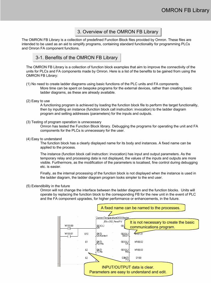
The OMRON FB Library is a collection of predefined Function Block files provided by Omron. These files areintended to be used as an aid to simplify programs, containing standard functionality for programming PLCsand Omron FA component functions.
3-1. Benefits of the OMRON FB Library
The OMRON FB Library is a collection of function block examples that aim to improve the connectivity of theunits for PLCs and FA components made by Omron. Here is a list of the benefits to be gained from using theOMRON FB Library:
(1) No need to create ladder diagrams using basic functions of the PLC units and FA componentsMore time can be spent on bespoke programs for the external devices, rather than creating basicladder diagrams, as these are already available.
(2) Easy to useA functioning program is achieved by loading the function block file to perform the target functionality,then by inputting an instance (function block call instruction: invocation) to the ladder diagramprogram and setting addresses (parameters) for the inputs and outputs.
(3) Testing of program operation is unnecessaryOmron has tested the Function Block library. Debugging the programs for operating the unit and FAcomponents for the PLCs is unnecessary for the user.
(4) Easy to understandThe function block has a clearly displayed name for its body and instances. A fixed name can beapplied to the process.
The instance (function block call instruction: invocation) has input and output parameters. As thetemporary relay and processing data is not displayed, the values of the inputs and outputs are morevisible. Furthermore, as the modification of the parameters is localised, fine control during debuggingetc. is easier.
Finally, as the internal processing of the function block is not displayed when the instance is used inthe ladder diagram, the ladder diagram program looks simpler to the end user.
(5) Extendibility in the futureOmron will not change the interface between the ladder diagram and the function blocks. Units willoperate by replacing the function block to the corresponding FB for the new unit in the event of PLCand the FA component upgrades, for higher performance or enhancements, in the future.
OMRON FB Library
INPUT/OUTPUT data is clear.Parameters are easy to understand and edit.
A fixed name can be named to the processes.
It is not necessary to create the basiccommunications program.

3-2-1. Example of using the OMRON FB Library - 1
Controlling the predefined components made by Omron can be easily achieved from the PLC ladder diagram.
- Ability to configure low-cost communications (RS-232C/485)
Serial communications (Compoway/F protocol)
Temperaturecontroller
Smart sensor
Omron Components
CS/C J SeriesPLC
Access by Function BlockFB
Example: Communication betweenTemperature controller and PLC
OMRON FB Library
Vision sensor

3-2-2. Example of using the OMRON FB Library - 2
High performance communications can be made by DeviceNet level.
- Ability to communicate between PLC and DeviceNet slaves easily.
OMRON FB Library
DeviceNet
Inverter
Generic slaves such as IO terminal
CS/CJ series PLC
Communicate between PLC and the devices
PLC Wireless
Temperature controller
FB
Example: data exchange between PLC and the slave devices
Access by Function block

The OMRON FB Library consist of the following:
3-3. Content of the OMRON FB Library
3-3-1. OMRON FB Part Files
The OMRON FB Part file is prepared using the ladder diagram function block, for defining each function ofthe PLC unit and the FA component.The files contain a program written in ladder diagram and have the extension .CXF.The file name of the OMRON FB Part file begins with ‘_’ (under score).When the OMRON FB Library is installed onto a personal computer, the OMRON FB Part files areclassified in the folder appropriate to each PLC Unit and FA component in the Omron Installation directory.
3-3-2. Library reference
The library reference describes the operation specifications of the OMRON FB Part file, and the specificationsof the input and the output parameters for each. The file format for this is PDF.When the OMRON FB Library is used, the user should select the OMRON FB Part file, set the input / outputparameters, and test the program operations referring to the library reference.
OMRON FB Library

CX-One / CX-Programmer Ver.6.0 installation CD contains the OMRON FB Library files.The user can select to install the OMRON FB Library during the installation of CX-One / CX-ProgrammerVer.6.0.
3-4. File Catalog and Where to Access the OMRON FB Library
3-4-2. CX-One / CX-Programmer installation CD
3-4-3. Accessing OMRON FB Library files from Web server
The latest version OMRON FB Library files are provided by Omron on the Web server.New files will be added to support new or enhanced PLC units and FA components.The download service of the OMRON FB Library is provided as a menu of Omron Web in each country.
Type Target componentsNumber of OMRONFB Part files (at thetime of February ’05)
FA components Temperature controller, Smart sensor, IDsensor, Vision sensor, 2 dimensions barcode reader, Wireless terminal
approx. 80
PLC CPU unit, Memory card, Special CPU IOunit (Ethernet, Controller Link, DeviceNetunit, Temperature control unit
approx. 95
Motion controlcomponents
Position control unitInverterServo motor driver
approx. 70
3-4-1. Catalog of OMRON FB Library files
OMRON FB Library
The internet
The internet
Web server
CX-Programmer Ver.6.0Install CD


This chapter describes how to use OMRON FB Library using the OMRON FB Part file ‘Make ON Time/OFFTime Clock Pulse in BCD’.
1. Explanation of the target program1. Explanation of the target program
1-1. Application Specifications
The target application specifications are as follows :-- Pulse is generated after PLC mode is changed to‘run’ or ‘monitor’ mode.- Output the pulse to address 1.00.- On time of generated pulse is set at D100.- Off time of generated pulse is 2 seconds.
1-2. Specifications of the OMRON FB Part file
The OMRON FB Part file ‘Make ON Time/OFF Time Clock Pulse in BCD’ has the following specifications:-
Explanation of target ProgramExplanation of target Program
Opening a new projectOpening a new project
Import FB LibraryImport
FB LibraryCreating a program
Creating a program Program CheckProgram Check
Offline Operation

Explanation of target ProgramExplanation of target Program
Opening a new projectOpening a new project
Import FB LibraryImport
FB LibraryCreating a program
Creating a program Program CheckProgram Check
Offline Operation
1-3. Input program
Create the following ladder program:-
[Reference] If created as a straightforward ladder diagram, the program would be as below:-

2. Opening a new project and setting the Device Type2. Opening a new project and setting the Device Type
Click
Click the left mouse button
! To use Function Blocks, select the following PLCs: CS1G-H, CS1H-H, CJ1G-H, CJ1H-H, CJ1M
Click the toolbar button [New] in CX-Programmer.
Click the left mouse button.
Click the left mouse button to select CPU type.
Click [OK] to decide the selected CPU type.
Explanation of target ProgramExplanation of target Program
Opening a new projectOpening a new project Import FB LibraryImport FB Library Creating a
programCreating a program Program CheckProgram Check
Offline Operation
Explanation of target ProgramExplanation of target Program
Opening a new projectOpening a new project
Import FB Library
Import FB Library
Creating a program
Creating a program Program CheckProgram Check
Offline Operation

3. Main Window functions3. Main Window functions
The main window functionality is explained here.
Title bar
Menus
Project TreeProject Tree
SectionSection
Project WorkspaceProject Workspace Ladder WindowLadder Window
Enables you to divide a program into several blocks. Each can be created anddisplayed separately.Section
Shows information such as a PLC name, online/offline state, location of the active cell.Status Bar
Shows Function Block definition.
By selecting the icons, you can copy or delete the selected Function Block definition.
- is shown if the file is a OMRON FB Part file. - In the case of a User-defined Function Block, is shown if Ladder, is shown if ST.
Function Block Definition
A screen for creating and editing a ladder program.Ladder Window
Controls programs and data. Enables you to copy element data by executing Drag and Drop between different projects or from within a project.
Project WorkspaceProject Tree
Enables you to select functions by clicking icons. Select [View] -> [Toolbars], displaytoolbars. Dragging toolbars enables you to change the display positions.Toolbars
Enables you to select menu items.Menus
Shows the file name of saved data created in CX-Programmer.Title Bar
Contents / FunctionName
Tool bar
Status bar
Function Block DefinitionFunction Block Definition

4. Import the OMRON FB Part file4. Import the OMRON FB Part file
Click mouse right button→ Insert Function Block→ Library File
Select Function Block definition icon from the project tree using the mouse cursor, right click. Select Insert Function Block, then select a Library file using mouse to navigate.
Select the necessary OMRON FBPart file in the ‘Select FunctionBlock Library’ dialog.
! The default path of the OMRON FB Library is C:\Program Files\Omron\CX-One\Lib\FBL.
Double click mouse left button.→ [OmronLib]→ [Programmable Controller]→ [CPU]Select each of the above inseries.
Left Click‘_CPU007_MakeClockPulse_BCD.cxf’
Left Click the [Open] button
Function Block DefinitionFunction Block Definition
Function Block definition ‘_CPU007_MakeClockPulse_BCD’is registered as part of the project file.
Double click mouse left button
Explanation of target ProgramExplanation of target Program
Opening a new projectOpening a new project Import FB LibraryImport FB Library Creating a
programCreating a program Program CheckProgram Check
Offline Operation
! You can easily check specifications ofOMRON FB part files by selectingregistered OMRON FB part files and [FBLibrary Reference] from a pop-up menuand showing a library reference file.

5. Program Creation
Confirm cursor position is at the upper left of Ladder Window to start programming.
5-1. Enter a Normally Open Contact
Press the [C] key on the keyboard to open the [New Contact] dialog. Use the dropdownbox to select the “P_On” symbol.
C
P_On
ENT
“P_On” is a system defined symbol. Its state is always ON.0 of the upper digit of an address is omitted when shown.[.] (period) is displayed between a channel number and a relay number.
Deleting instructions• Move the cursor to the instruction and
then press the DEL key or• Move the cursor to the right cell of
the instruction and press the BS key.
Explanation of target ProgramExplanation of target Program
Opening a new projectOpening a new project
Import FB Library
Import FB Library
Creating a program
Creating a program Program CheckProgram Check
Offline Operation

5-2. Entering an Instance
Press the [F] key on the keyboard to open the [New Function Block Invocation] dialog.F
Enter text to create an FB instance name. [WorkInputTimingGenerator ]
ENT
Applies a name for the specificprocess in the diagram.
Applies a name for the specificprocess in the diagram.
Shows FB instance (invocation) ‘WorkInputTimingGenerator’.
P
[d100]
ENT Choose an address for the input parameter ‘OnTime’.
5-3. Entering Parameters
or ENT Move the cursor to the left of input parameter.
Enter the address.
Explanation of target ProgramExplanation of target Program
Opening a new projectOpening a new project
Import FB LibraryImport
FB LibraryCreating a program
Creating a program Program CheckProgram Check
Offline Operation

Enter the remaining parameters in the same way.
P Or ENT
#10
ENT
O
1.00
ENT
[Generated Pulse]
ENT
Please add the following prefix forentering constants as parameters: “#” (Hexadecimal/BCD)
Or “&” (Decimal)
Explanation of target ProgramExplanation of target Program
Opening a new projectOpening a new project
Import FB LibraryImport
FB LibraryCreating a program
Creating a program Program CheckProgram Check
Offline Operation

6. Program Error Check (Compile)
Before program transfer, check for errors using the program compile.
Click
Double-click on displayed errors,and the Ladder Diagram cursorwill move to the corresponding error location, displaying the error rung in red.
Double-click on displayed errors,and the Ladder Diagram cursorwill move to the corresponding error location, displaying the error rung in red.
Modify the error.Modify the error.
� Output Window automatically opens at program check.� The cursor moves to an error location by pressing J or F4 key.� Output Window closes by pressing the ESC key.
Explanation of target ProgramExplanation of target Program
Opening a new projectOpening a new project
Import FB Library
Import FB Library
Creating a program
Creating a program Program CheckProgram Check
Offline Operation
Errors and addresses aredisplayed in the Output Window.
Errors and addresses aredisplayed in the Output Window.

7. Going Online
Online/debug functions when working online with CX-Simulator areexplained in this guide (Install CX-Simulator separately).
Online/debug functions when working online with CX-Simulator areexplained in this guide (Install CX-Simulator separately).
Click [OK]
Click [OK]
The background color ofthe Ladder Windowchanges to gray.
The background color ofthe Ladder Windowchanges to gray.
Scan time is displayed(except during Program Mode).
Scan time is displayed(except during Program Mode).
The operating mode ofthe active PLC isshown.
The operating mode ofthe active PLC isshown.
Click
The CX-SimulatorConsole box is shown.
The CX-SimulatorConsole box is shown.
CX-Programmer provides three methods of connecting, depending on usage.
Program transfer starts.
Online to transferOnline
to transfer MonitoringMonitoring Online Edit
Online Edit
Online Operation
Normal online. Enables you to go online with a PLC of the device type and method specified when opening a project. Normal online. Enables you to go online with a PLC of the device type and method specified when opening a project.
Auto online. Automatically recognizes the connected PLC and enables you to go online with a PLC with one button. -> Uploads all data, such as programs, from the PLC.
Auto online. Automatically recognizes the connected PLC and enables you to go online with a PLC with one button. -> Uploads all data, such as programs, from the PLC.
Online with Simulator. Enables you to go online with CX-Simulator with one button (CX-Simulator must be installed.) Online with Simulator. Enables you to go online with CX-Simulator with one button (CX-Simulator must be installed.)

8. Monitoring - 1
The on/off status of contacts and coils can be monitored.
Click
Change the PLC (Simulator) to Monitor mode.
Change the PLC (Simulator) to Monitor mode.
Click [Yes].
The monitored area isdisplayed in a specifiedcolor.
The monitored area isdisplayed in a specifiedcolor.
The current values ofparameters areshown.
The current values ofparameters areshown.
If your program has a large volume of data, the scroll speed of the screen may become slow when monitoring.To resolve this, click the icon below to cancel monitoring, scroll to the address you want to monitor, then restart the monitor mode.
��� toggles PLC monitoring on/off
Online to transferOnline
to transfer MonitoringMonitoring Online Edit
Online Edit
Online Operation

9. Monitoring - 2 Change Parameter Current Value
Change the current value of contact/coils or word data in the Ladder Window.
Change the current value of Inputparameter.Change the current value of Inputparameter.
Move the cursor to the input parameter ‘D100’.
Click mouse right button and select the menu item[Set/Reset(S)] → [Setting Value (V)] Or
Double click mouse left button.
ENT
OrClick [Set]Click [Set]
Online to transferOnline
to transfer MonitoringMonitoring Online Edit
Online Edit
Online Operation
Please add the following prefix forentering constants as parameters: “#” (Hexadecimal/BCD)
Or “&” (Decimal)

10. Online Editing
Move the cursor to the rungrequiring modification.
Select [Program] → [Online Edit] → [Begin]
Shortcut: [Ctrl]+[E]
Edit the address to the required bit number (4.11 in the example)
Select [Program] → [Online Edit] → [Send Change]
Shortcut: [Ctrl]+{Shift]+[E]
Double click
End
You can also select multiplerungs by using the Drag & Dropfacility with the mouse.
Move the cursor to a instruction you want to modify. Double click the left mouse button.
Online to transferOnline
to transfer MonitoringMonitoring Online Edit
Online Edit
Online Operation


Explanation of target ProgramExplanation of target Program Copy of FB partCopy of FB part Change of
FB DefinitionChange of
FB Definition
1. Explanation of target program
1-1. Changing File Specifications
The OMRON FB Part file ‘Make ON Time/OFF Time Clock Pulse in BCD’ is designed to repeatedly turn offthe ENO for the specified OffTime (unit: 100 msec) and on for the specified OnTime (unit: 100 msec). In thisexample, the OMRON FB Part file will be changed to output an invert signal by adding the output parameter‘INV_ENO’.
1-2. Changing the contents of the OMRON FB Part file
To satisfy the requirement described above, the following changes must be made to OMRON FB Part file‘Make ON Time/OFF Time Clock Pulse in BCD’
1. Add an output parameter ‘INV_ENO’.2. Add ladder program to output the ENO for inverting the signal.
OffTime(*100ms)
OnTime(*100ms)
EN ON OFF
ENO ON OFF
INV_ENO ON OFF
This chapter describes how to customize the OMRON FB Library using the OMRON FB Part file ‘Make ONTime/OFF Time Clock Pulse in BCD’.
CautionOMRON cannot guarantee the operation of a customized OMRON FB parts. Please be sure to check the process of your FB part sufficiently before customization and confirm the operation of each FB parts thoroughly after that.
CautionOMRON cannot guarantee the operation of a customized OMRON FB parts. Please be sure to check the process of your FB part sufficiently before customization and confirm the operation of each FB parts thoroughly after that.
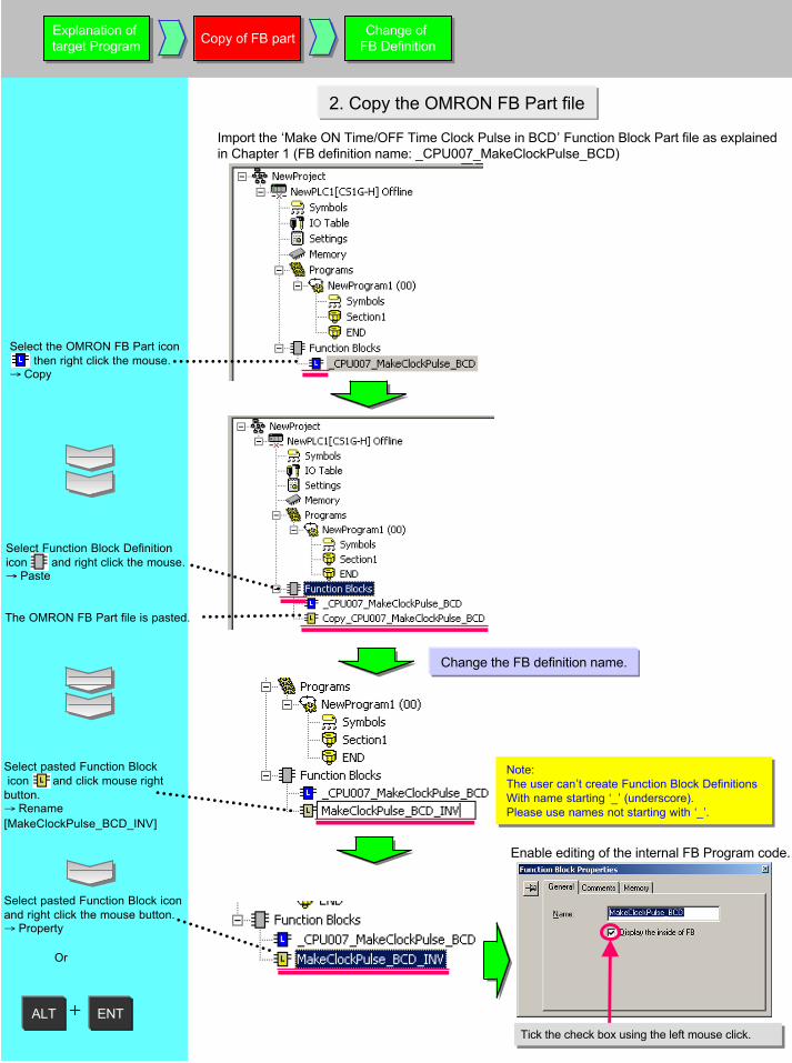
2. Copy the OMRON FB Part file
Select the OMRON FB Part icon then right click the mouse.→ Copy
Import the ‘Make ON Time/OFF Time Clock Pulse in BCD’ Function Block Part file as explained in Chapter 1 (FB definition name: _CPU007_MakeClockPulse_BCD)
Select pasted Function Block icon and click mouse right button.→ Rename[MakeClockPulse_BCD_INV]
Note:The user can’t create Function Block Definitions With name starting ‘_’ (underscore).Please use names not starting with ‘_’.
Note:The user can’t create Function Block Definitions With name starting ‘_’ (underscore).Please use names not starting with ‘_’.
ALT ENT
Select pasted Function Block icon and right click the mouse button.→ Property
Or
Enable editing of the internal FB Program code.
Tick the check box using the left mouse click.Tick the check box using the left mouse click.
Explanation of target ProgramExplanation of target Program Copy of FB partCopy of FB part Change of
FB DefinitionChange of
FB Definition
Change the FB definition name.
Select Function Block Definitionicon and right click the mouse.→ Paste
The OMRON FB Part file is pasted.

3. Add a variable to the Function Block
Open the Function Block Ladder Editor.
Select the Function Block icon using the mouse cursor and double click the left mouse button.
Select Output tab in VariableTable using the mouse cursor And click the left mouse button.
Click the left mouse button and select Insert Variable(I).
Enter a new variable name.Enter a new variable name.
Select BOOL for bit data.Select BOOL for bit data.
Explanation of target ProgramExplanation of target Program Copy of FB partCopy of FB part Change of
FB DefinitionChange of
FB Definition
Opens the FunctionBlock LadderEditor.
Opens the FunctionBlock LadderEditor.
Variable TableVariable Table
Ladder EditorLadder Editor
Variable table
Confirm the entered variable iscorrect.
The original OMRON FB Part file is also able to display its ladder program, but cannot be edited.The original OMRON FB Part file is also able to display its ladder program, but cannot be edited.

4. Changing the Function Block Ladder
Add the required ladder diagram on Function Block Ladder edit field.Move the cursor to the left column of the next rung.
ENO
ENT
4-1. Entering a Contact
/
O
INV_ENO
ENT
Explanation of target ProgramExplanation of target Program Copy of FB partCopy of FB part Change of
FB DefinitionChange of
FB Definition

Explanation of target ProgramExplanation of target Program Copy of FB partCopy of FB part Change of
FB DefinitionChange of
FB Definition
4-2. Checking Usage Status of Variables
As with main ladder program, you can use cross reference pop-up to check usage conditions ofvariables.
Alt 4
Display cross referencepop-up.
Move the cursor.Move the cursor.
You can see that variable ENO is used in an output coil in the step No.20 as well.
Se le c t L DNOT f ro m cr ossreference pop-up by the mousecursor.
The cursor in the FB Ladder Editor moves to the output coil in the step No.20.


2. Explanation of the target program
This example describes how to create an ST program in a Function Block to calculate the average value of ameasured thickness.
1. What is the ST Language?
The ST (Structured Text) language is ahigh-level language code for industrialcontrols (mainly PLCs) defined by the IEC61131-3 standard.It has many control statements, includingIF-THEN-ELSE-END_IF, FOR / WHILE loop,and many mathematical functions such asSIN / LOG. it is suitable for mathematicalprocessing.The ST language supported by CX-Programmer is in conformance with IEC61131-3 standard.The arithmetic functions in CX-ProgrammerVer.5/6 are as follows:
sine (SIN), cosine (COS), tangent(TAN), arc-sine (ASIN), arc-cosine(ACOS), arc-tangent (ATAN),square root (SQRT), absolutevalue (ABS), logarithm (LOG),natural-logarithm (LN), natural-exponential (EXP), exponentiation(EXPT)
Reference: The IEC 61131 standard is an international standard for programming Programmable LogicControllers (PLC), defined by the International Electro-technical Commission (IEC).The standard consists of 7 parts, with part 3 defining the programming of PLCs.
The data type should be set to REAL to store the data.REAL type allows values with 32 bits of length, see range below:-
-3.402823 1038 ~ -1.175494 10-38, , 0,+1.175494 10-38 ~ +3.402823 1038
The data type should be set to REAL to store the data.REAL type allows values with 32 bits of length, see range below:-
-3.402823 1038 ~ -1.175494 10-38, , 0,+1.175494 10-38 ~ +3.402823 1038
FB definition name AverageCalc_3Value
Input symbols x(REAL type), y(REAL type), z(REAL type)
Output symbol score(REAL type)
ST Program definition score := (x + y + z) / 3.0;
FB definition name AverageCalc_3Value
Input symbols x(REAL type), y(REAL type), z(REAL type)
Output symbol score(REAL type)
ST Program definition score := (x + y + z) / 3.0;
Substitute a value to a symbol is expressed by “ := ”.Substitute a value to a symbol is expressed by “ := ”. Enter “ ; ” (semicolon) to complete the code.
Enter “ ; ” (semicolon) to complete the code.
Explanation of target ProgramExplanation of target Program
Create new FB DefinitionCreate new FB Definition
Entering VariablesEntering Variables
Creating ST ProgramCreating
ST Program
Offline Operation
Creating Ladder Program and check
Creating Ladder Program and check

3. Create a Function Block using ST
Create a Function Block using Structured Text.
Select the Function Block iconusing a mouse cursor, and clickthe right mouse button.→ Insert Function Block(I)→ Structured Text(S)
Select the Function Block definition icon using the mouse cursor and right click the mouse button. Select Paste.→ RenameEnter [AverageCalc_3value]
Open Function Block ST EditorOpen Function Block ST Editor
Select Function Block definition Icon by mouse cursor and double click the left mouse button.
Change the Function Block definition nameChange the Function Block definition name
A New Function Block definition is created.
Variable TableVariable Table
ST Edit FieldST Edit Field
Note:The user can’t create Function Block Definitionswith names starting ‘_’ (underscore).Please use names not starting with ‘_’.
Note:The user can’t create Function Block Definitionswith names starting ‘_’ (underscore).Please use names not starting with ‘_’.
Explanation of target ProgramExplanation of target Program
Create new FB DefinitionCreate new FB Definition
Entering VariablesEntering Variables
Creating ST ProgramCreating
ST Program
Offline Operation
Creating Ladder Program and check
Creating Ladder Program and check

4. Entering Variables into Function Blocks
Select Variable Table.
Select the Input tab using the mouse cursor.
Select Insert from the Pop-up menu.
Enter a variable nameEnter a variable name
Select REALSelect REAL
Enter and applicable commentEnter and applicable comment
Enter input symbol x, output symbols y,z by repeating the process above.Enter input symbol x, output symbols y,z by repeating the process above.
Reference: The copy and paste operation is available in FB Header.Reference: The copy and paste operation is available in FB Header.
Input VariablesInput Variables
Output VariablesOutput Variables
Reference: The order of the variables in the FB table becomes the order of parameters on FB instance (invocation) in the normal ladder view. To change the order, it is possible to drag & drop variables within the table.
Reference: The order of the variables in the FB table becomes the order of parameters on FB instance (invocation) in the normal ladder view. To change the order, it is possible to drag & drop variables within the table.
FB instance (invocation)
Input Variables
Output Variables
Enter data for the following.NameData typeComment
Explanation of target ProgramExplanation of target Program
Create new FB DefinitionCreate new FB Definition
Entering VariablesEntering Variables
Creating ST ProgramCreating
ST Program
Offline Operation
Creating Ladder Program and check
Creating Ladder Program and check

5. Entry of ST program
Select the ST Editor text field in the Function Block ST Editor window.
Enter text into the field: “score := (x + y + z) / 3.0;”.Enter text into the field: “score := (x + y + z) / 3.0;”.
Reference: User may type Comments in the ST program. Enter ‘(*’ and ‘*)’ both ends of comment strings, see below.
This is useful for recording change history, process expressions, etc.
Reference: User may type Comments in the ST program. Enter ‘(*’ and ‘*)’ both ends of comment strings, see below.
This is useful for recording change history, process expressions, etc.
When the input expression is a real type calculation, please enter the constant value with decimal point and zero forsingle decimal places, e.g. ‘3.0’.
Explanation of target ProgramExplanation of target Program
Create new FB DefinitionCreate new FB Definition
Entering VariablesEntering Variables
Creating ST ProgramCreating
ST Program
Offline Operation
Creating Ladder Program and check
Creating Ladder Program and check
Note: You can jump to a help topic that showsST control syntax by selecting [ST Help]from a pop-up menu in the ST Editor.
Note: You can jump to a help topic that showsST control syntax by selecting [ST Help]from a pop-up menu in the ST Editor.

6. Entering the FB to the Ladder Program and error checking
Enter the following FB into the ladder program.Instance name: ThicknessAvarageInput parameters: D0, D2, D4Output parameter: D6
Refer page 2-7 for entering FB instances.Entering ST FB instances is the same as entering FB Ladder instances.
Refer page 2-7 for entering FB instances.Entering ST FB instances is the same as entering FB Ladder instances.
Perform a programs check before transferring the program.
Refer page 2-9 for program checking.The functionality is the same as for Function Block Ladder instances.Refer page 2-9 for program checking.The functionality is the same as for Function Block Ladder instances.
It is possible to change or add variables in the Function Block after inputting FB instanceinto the ladder editor. If modified, the Ladder editor changes the color of the left bus-barof the rung containing the changed Function Block.When this occurs, please select the instance in the Ladder Editor using the mousecursor, and select Update Function Block Instance (U) from the pop-up menu.
It is able to jump the referred function block definition by entering [Shift]+[F] key when the cursor is in the function block instance.
It is able to jump the referred function block definition by entering [Shift]+[F] key when the cursor is in the function block instance.
Explanation of target ProgramExplanation of target Program
Create new FB DefinitionCreate new FB Definition
Entering VariablesEntering Variables
Creating ST ProgramCreating
ST Program
Offline Operation
Creating Ladder Program and check
Creating Ladder Program and check

7. Program Transfer
Go online to the PLC with CX-Simulator and transfer the program.
The on/off status of contacts and coils can be monitored.
Click
Change the PLC(Simulator) to Monitormode.
Change the PLC(Simulator) to Monitormode.
Click [Yes]
Refer to page 2-10 for steps to go online and transfer the program.Refer to page 2-10 for steps to go online and transfer the program.
Confirm that the PLC is Monitor mode.
MonitoringMonitoring
Online Operation
Transfer ProgramTransfer Program

8. Monitoring the Function Block execution
Monitors the present value of parameters in the FB instance using the Watch Window.
Alt 3
ENT
Click Browse… button using the mouse left button. Select REAL(32bit floating point)Select REAL(32bit floating point)
Select ThicknessAvarage.xSelect ThicknessAvarage.x
Click [OK] button using theleft mouse button.
When monitoring internal variables at debug phase,collective registration is available in addition to theindividual registration on the Watch Windowthrough the operation shown here. For the details,refer “5-8 Batch Registration to Watch Window”.When the function block is a ladder, conductingmonitoring is available. For the details, refer “5-5Operation Check- 1”
Display the Watch Window.
Open the Edit dialog.
Click the button using theleft mouse button, then selectthe following:[Symbols of type][Name or address]
MonitoringMonitoring
Online Operation
Transfer ProgramTransfer Program

Reference: Example of an ST program using IF-THEN-ELSE-END_IF
The following ST program checks the average value calculated by the example of page 4-7 against a range (upperlimit or lower limit).
FB Definition: OutputOfDecisionResultInput symbols: score(REAL type), setover(REAL type), setunder REAL type)Output symbols: OK (BOOL type), overNG(BOOL type), underNG(BOOL type)
ST program:
IF score > setover THEN (* If score > setover, *) underNG := FALSE; (* Turn off underNG *) OK := FALSE; (* Turn off OK *) overNG := TRUE; (* Turn on o erNG *)
ELSIF score < setunder THEN (* if score =< setover and score < setunder then *) overNG := FALSE; (* Turn on overNG *) OK := FALSE; (* Turn off OK *) underNG := TRUE; (* Turn on underNG *)
ELSE (* if setover > score > setunder then*) underNG := FALSE; (* Turn off underNG *) overNG := FALSE; (* Turn off overNG *) OK := TRUE; (* Turn off OK *)
END_IF; (* end of IF section*)
Example of an FB instance (the instance name is ‘ThicknessDecision’)


This chapter describes how to componentize a user program with an example using function blocks.
1. Overview
2. How to Proceed Program Development
Generally shown below is a workflow to create a user program with componentization in the case ofthe application example below. Deliberate consideration is required especially in program designprocess.
(1) Program Design(2) Creating Components (2-1) Entering FB Component (2-2) Debugging FB Component (2-3) Creating FB Component Library (File Save)(3) Using Components in Application (3-1) Importing Components (3-2) Using Components for Program (3-3) Debugging Program(4) Start-Up
3. Application Example
MeasuringDVD thickness
Inspection Packing
Assortment
Shown here is a DVD inspection machine as an example for application.Process can be primarily categorized into inspection, packing, and assortment.
ProgramDesign
ProgramDesign
Entering/Debugging FBDefinition
Entering/Debugging FBDefinition
Creating FBDefinitionLibrary
Creating FBDefinitionLibrary
Entering MainProgram
Entering MainProgram
DebuggingMain ProgramDebugging
Main Program
Advanced

Application can be materialized by using hardware and software (program) through combinationof requirements.Following sections describe how to proceed program design using an application exampledescribed before.
4. How to Proceed Program Development
4-1 Overview of Design Process
Specifications should be repeatedlydetailed and integrated to divide andclassify them as shown in the right.
4-2 Extracting Requirement Specifications
Shown below are the extracted requirement specifications for this application. Overview of DVD Inspection Machine (Requirement Specifications)Req. 1. DVD should be inserted from a loader.Req. 2. Thickness of DVD should be measured at 3 points. Average thickness of measurements
should be calculated. If it is within its threshold range, DVD should be assorted into astocker for good products, or a stocker for bad products if not.
Req. 3. Good DVDs should be packed into the case.Req. 4. Packed DVDs should be packed into the paper box.Req. 5. Paper boxes should be classified into 2 types. Switching frequency should be counted to
evaluate a life of limit switch adjacent to actuator of selection part.Req. 6. Other requirements* To simplify the description, this document focuses on a part of device (underscored).
Input from Client
RequirementSpecifications
for Device DetailedSpecifications
GeneralSpecifications
GeneralSpecifications
GeneralSpecifications
DetailedSpecifications
DetailedSpecifications
DetailedSpecifications
DetailedSpecifications
Detailing
Integrating
ProgramDesign
ProgramDesign
Entering/Debugging FBDefinition
Entering/Debugging FBDefinition
Creating FBDefinitionLibrary
Creating FBDefinitionLibrary
Entering MainProgram
Entering MainProgram
DebuggingMain ProgramDebugging
Main Program
Advanced
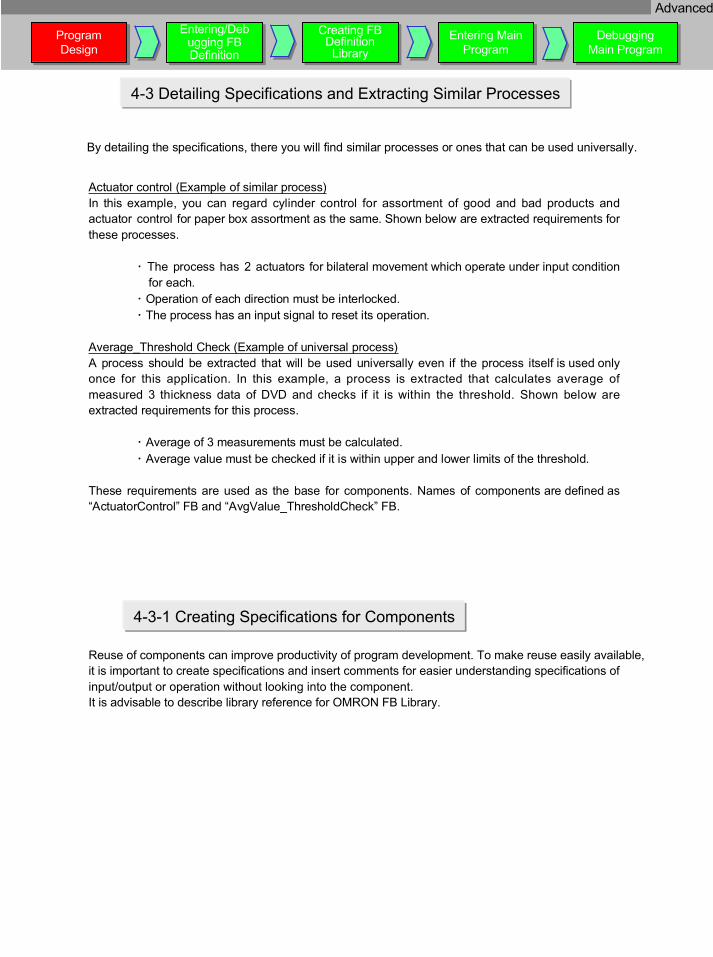
Actuator control (Example of similar process)In this example, you can regard cylinder control for assortment of good and bad products andactuator control for paper box assortment as the same. Shown below are extracted requirements forthese process
�
es.
The process has 2 actuators for bilateral movement which operate under input conditionfor each
�.
Operation of each direction must be interlo�
cked. The process has an input signal to reset its operation.
Average_Threshold Check (Example of universal process)A process should be extracted that will be used universally even if the process itself is used onlyonce for this application. In this example, a process is extracted that calculates average ofmeasured 3 thickness data of DVD and checks if it is within the threshold. Shown below areextracted requirements for this proce
�
ss.
Average of 3 measurements must be calculat�
ed. Average value must be checked if it is within upper and lower limits of the threshold.
These requirements are used as the base for components. Names of components are defined as“ActuatorControl” FB and “AvgValue_ThresholdCheck” FB.
4-3 Detailing Specifications and Extracting Similar Processes
4-3-1 Creating Specifications for Components
Reuse of components can improve productivity of program development. To make reuse easily available,it is important to create specifications and insert comments for easier understanding specifications ofinput/output or operation without looking into the component.It is advisable to describe library reference for OMRON FB Library.
ProgramDesign
ProgramDesign
Entering/Debugging FBDefinition
Entering/Debugging FBDefinition
Creating FBDefinitionLibrary
Creating FBDefinitionLibrary
Entering MainProgram
Entering MainProgram
DebuggingMain ProgramDebugging
Main Program
By detailing the specifications, there you will find similar processes or ones that can be used universally.
Advanced

“ActuatorControl” FBIt should be described in a ladder sequence because it is a process for sequence control.
4-3-2 Example of FB Component Creation
Line comments for operationaloverview and input and outputvariables allow for easierunderstanding.
“AvgValue_ThresholdCheck” FBIt should be described in ST because it is a process for numeric calculation and comparison.
Note: Use general names as long as possible for names of FB and variables in ladder diagram and ST,instead of specific names for the function at creation.Note: Use general names as long as possible for names of FB and variables in ladder diagram and ST,instead of specific names for the function at creation.
[Input Variables]
[Output Variables]
[Internal Variables]None.
[Input Variables]
[Output Variables]
[Internal Variables]
ProgramDesign
ProgramDesign
Entering/Debugging FBDefinition
Entering/Debugging FBDefinition
Creating FBDefinitionLibrary
Creating FBDefinitionLibrary
Entering MainProgram
Entering MainProgram
DebuggingMain ProgramDebugging
Main Program
Advanced

Detailed process components are extracted by now. Components for application will be created bycombining them in the following sections.
4-4. Integrating FBs
Req. 2. “Thickness of DVD should be measured at 3 points. Average thickness of measurementsshould be calculated. If it is within its threshold range, DVD should be assorted into a stocker forgood products, or a stocker for bad products if not.” can be regarded as a process that combines“AvgValue_ThresholdCheck” and “ActuatorControl” investigated in the previous section. “Combining”these components allows creation of integrated component “DVD_ThickSelectControl” FB. Shownbelow is an example of an FB to be created.
4-4-1. Combining Existing Components - DVD_ThickSelectControl
[Input Variables]
[Output Variables]
[Internal Variables]
A function block can be called from within another function block. This is called “nesting”.To nest, declare a variable of FUNCTION BLOCK(FB) type as its internal variable to use thevariable name as an instance.
A function block can be called from within another function block. This is called “nesting”.To nest, declare a variable of FUNCTION BLOCK(FB) type as its internal variable to use thevariable name as an instance.
InputVariablesInputVariables
OutputVariablesOutputVariables
InternalVariablesInternalVariables
This FB has its specific name and variablenames that include “DVD” or “Cylinder”because it is specifically created forapplication.
This FB has its specific name and variablenames that include “DVD” or “Cylinder”because it is specifically created forapplication.
ProgramDesign
ProgramDesign
Entering/Debugging FBDefinition
Entering/Debugging FBDefinition
Creating FBDefinitionLibrary
Creating FBDefinitionLibrary
Entering MainProgram
Entering MainProgram
DebuggingMain ProgramDebugging
Main Program
Advanced
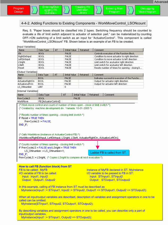
Req. 5. “Paper boxes should be classified into 2 types. Switching frequency should be counted toevaluate a life of limit switch adjacent to actuator of selection part.” can be materialized by countingOFF->ON switching of a limit switch as an input for “ActuatorControl”. This component is called“WorkMoveControl_LSONcount” FB. Shown below is an example of an FB to be created.
4-4-2. Adding Functions to Existing Components - WorkMoveControl_LSONcount
[Input Variables]
[Output Variables]
[Internal Variables]
How to call FB (function block) from STFB to be called: MyFB Instance of MyFB declared in ST: MyInstanceI/O variable of FB to be called: I/O variable to be passed to FB in ST: Input: Input1, Input2 Input: STInput1, STInput2 Output: Output1, Output2 Output: STOutput1, STOutput2
In this example, calling of FB instance from ST must be described as MyInstance(Input1 := STInput1, Input2 := STInput2, Output1 => STOutput1, Output2 => STOutput2);
When all input/output variables are described, description of variables and assignment operators in one to becalled can be omitted. MyInstance(STInput1, STInput2, STOutput1, STOutput2);
By describing variables and assignment operators in one to be called, you can describe only a part ofinput/output variables. MyInstance(Input1 := STInput1, Output2 => STOutput2);
Ladder FB is called from ST.Ladder FB is called from ST.
ProgramDesign
ProgramDesign
Entering/Debugging FBDefinition
Entering/Debugging FBDefinition
Creating FBDefinitionLibrary
Creating FBDefinitionLibrary
Entering MainProgram
Entering MainProgram
DebuggingMain ProgramDebugging
Main Program
Advanced

For components (FB) investigated here to work as a program, a circuit must be created that calls acomponent integrated from main ladder program.* Example here limits to Req.2 and 5.
4-5. Total Program Description
[Global Variables]
Why the instance name is “StageA***”?Although it is not explicitly described in the application example, a program for newly added stage Bcan be created only by describing an instance “StageB***” in the program and setting necessaryparameters, without registering a new function block.As a feature of Omron’s function block, one FB can have more than one instance. By using operation-verified FB definition (algorithm), a program can be created only by assigning its address.
Why the instance name is “StageA***”?Although it is not explicitly described in the application example, a program for newly added stage Bcan be created only by describing an instance “StageB***” in the program and setting necessaryparameters, without registering a new function block.As a feature of Omron’s function block, one FB can have more than one instance. By using operation-verified FB definition (algorithm), a program can be created only by assigning its address.
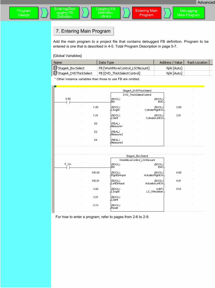
* Other instance variables than those to use FB are omitted.
Either right cylinder ON (2.00) orleft cylinder ON (2.01) as anoutput operates by using a limitswitch (1.00, 1.01) at cylinderdrive to assort DVD and 3measurements (D0-D5) of DVDthickness as inputs and by turningcontact 0.00 ON.
Either right cylinder ON (2.00) orleft cylinder ON (2.01) as anoutput operates by using a limitswitch (1.00, 1.01) at cylinderdrive to assort DVD and 3measurements (D0-D5) of DVDthickness as inputs and by turningcontact 0.00 ON.
Either right actuator ON (4.00) orleft actuator ON (4.01) turns ONbased on condition of a limit switch(3.00, 3.01) at actuator end whenoperation input (W0.00) and leftmove input (W0.01) to move a boxcontaining DVD to the right or left.Also, switching count of the limitswitch is provided to D10-13.
Either right actuator ON (4.00) orleft actuator ON (4.01) turns ONbased on condition of a limit switch(3.00, 3.01) at actuator end whenoperation input (W0.00) and leftmove input (W0.01) to move a boxcontaining DVD to the right or left.Also, switching count of the limitswitch is provided to D10-13.
ProgramDesign
ProgramDesign
Entering/Debugging FBDefinition
Entering/Debugging FBDefinition
Creating FBDefinitionLibrary
Creating FBDefinitionLibrary
Entering MainProgram
Entering MainProgram
DebuggingMain ProgramDebugging
Main Program
Advanced

This section verifies total program structure including components (function blocks) created here.
4-5-1. Total Program Structure
[Main Program]
Instance names and FB names can be illustrated as follows: (FB name is described in [ ])
In a structured program, especially to change a lower level component (FB), it is important to understandparent/children relationship and components’ sharing when process flow must be cleared in case of debugging, etc. Itis advisable to create an understandable diagram of total program structure as design documentation.
CX-Programmer Ver.6.0 provides “FB instance viewer” when [Alt]+[5] key is pressed for easier understanding ofsoftware structure constructed by FBs. Also, address can be checked that is assigned to FB instance.
ProgramDesign
ProgramDesign
Entering/Debugging FBDefinition
Entering/Debugging FBDefinition
Creating FBDefinitionLibrary
Creating FBDefinitionLibrary
Entering MainProgram
Entering MainProgram
DebuggingMain ProgramDebugging
Main Program
Main program StageA_DVDThickSelect[DVD_ThickSelectControl]
StageA_BoxSelect[WorkMoveControl_LSONcount]
DVD ThickJudge[AvgValue_ThresholdCheck]
WorkMove [ActuatorControl]
WorkMove [ActuatorControl]
Advanced

This section describes how to enter an actually-designed program and debug it.
New project must be created and “ActuatorControl” FB of Page 5-4 must be entered.
5. Entering FB Definition
ProgramDesign
ProgramDesign
Entering/Debugging FBDefinition
Entering/Debugging FBDefinition
Creating FBDefinitionLibrary
Creating FBDefinitionLibrary
Entering MainProgram
Entering MainProgram
DebuggingMain ProgramDebugging
Main Program
5-1. New Project Creation and PLC Model/CPU Type Setting
Refer to page 2-3 and create a new project.
5-2. Creating Ladder Definition FB
Create Ladder definition FB.
Move the mouse cursor to afunction block icon , thenright-click. Select→ Insert Function Block→ Ladder
Now new FB is created.
! Select a PLC model from the followings touse function blocks.
CS1G-H, CS1H-H, CJ1G-H, CJ1H-H, CJ1M
Advanced

Change FB definition name.
ProgramDesign
ProgramDesign
Entering/Debugging FBDefinition
Entering/Debugging FBDefinition
Creating FBDefinitionLibrary
Creating FBDefinitionLibrary
Entering MainProgram
Entering MainProgram
DebuggingMain ProgramDebugging
Main Program
Caution:A user cannot create function block definition namestarting from "_".The name must start from a character other than"_".
Caution:A user cannot create function block definition namestarting from "_".The name must start from a character other than"_".
Open FB ladder editor.Open FB ladder editor.
Move the mouse cursor to acopied function block icon ,then right-click. Select→ RenameEnter [ActuatorControl].
Move the mouse cursor to afunction block icon , thendouble-click to open thefunction block ST editor.
Select the variables table and register variables in the function block.All variables of “ActuatorControl” FB of page 5-4 must be registered.
Note: Order of variables must be the same as FB instance order.To change order of variables, select a variable name then drag and drop it.
Note: Order of variables must be the same as FB instance order.To change order of variables, select a variable name then drag and drop it.
Select ladder input screen, then enter a ladder program.All variables of “ActuatorControl” FB of page 5-4 must beregistered.
Note: Although you can enter a circuit in the FB ladder editor similar to the mainladder editor, entering of address in the FB is invalid.
Note: Although you can enter a circuit in the FB ladder editor similar to the mainladder editor, entering of address in the FB is invalid.
Note: To enter variable list in a line comment, you can select a variable fromvariables table then copy it. You can use it for more efficient input.
Note: To enter variable list in a line comment, you can select a variable fromvariables table then copy it. You can use it for more efficient input.
Ladder Input ScreenLadder Input Screen
Variables TableVariables Table
5-3. Entering FB Ladder Program
Advanced

Connect to CX-Simulator online, transfer a program, then set PLC (simulator) to monitor mode.
5-4. Transferring Program
ProgramDesign
ProgramDesign
Entering/Debugging FBDefinition
Entering/Debugging FBDefinition
Creating FBDefinitionLibrary
Creating FBDefinitionLibrary
Entering MainProgram
Entering MainProgram
DebuggingMain ProgramDebugging
Main Program
For how to connect online and transfer aprogram, see page 2-10.For how to connect online and transfer aprogram, see page 2-10.
Change current parameter value of FB invocation on the main ladder, then check the operation of“ActuatorControl” FB.Monitor the instance of ActuatorControl FB first.
5-5. Operation Check-1
Move the cursor to FBinvocation, then double-clickor click button.
FB ladder instance (undercondition of address assigned)is monitored.
Advanced

1 must be displayed.1 must be displayed.
5-6. Operation Check-2
ProgramDesign
ProgramDesign
Entering/Debugging FBDefinition
Entering/Debugging FBDefinition
Creating FBDefinitionLibrary
Creating FBDefinitionLibrary
Entering MainProgram
Entering MainProgram
DebuggingMain ProgramDebugging
Main Program
Display the main ladder and FB instance (FB ladder invoked by the main ladder) at the sametime, then check the operation while changing current parameter value of FB invocation in themain ladder.
(1) Initial State: Turn 0.03 ON. => 0.04 and 0.05 must be OFF. FB instance ladder monitor screenmust be under state that corresponds to the value.
(2) Actuator forward direction operation-1: Turn 0.00 ON => 0.04 must be turned ON. FB instanceladder monitor screen must be under state that corresponds to the value.
(3) Actuator forward direction operation-2: Turn 0.03 OFF => 0.04 must be ON and 0.05 must beOFF. FB instance ladder monitor screen must be under state that corresponds to the value.
(4) Actuator forward direction operation-3: Turn 0.02 ON => 0.04 must be OFF and 0.05 must beOFF. FB instance ladder monitor screen must be under state that corresponds to the value.
Move the cursor to 0.03 andpress [ENT] key.
Enter 1 and press [Set] button.Enter 1 and press [Set] button.
Enter following parameter values of FB invocation and check if expected output should be provided.In this example only (1) is shown, but all combination of conditions must be verified.
Advanced

Select a name to register,then press [OK] button.Select a name to register,then press [OK] button.
ProgramDesign
ProgramDesign
Entering/Debugging FBDefinition
Entering/Debugging FBDefinition
Creating FBDefinitionLibrary
Creating FBDefinitionLibrary
Entering MainProgram
Entering MainProgram
DebuggingMain ProgramDebugging
Main Program
5-7. Entering/Debugging Other FB Definition
Thus far, entering and debugging for “ActuatorControl” FB are described. Other FB definitionmust be entered and debugged as well.
5-8. Batch Registration to Watch Window
For debugging, you can use batch registration of FB instance address to Watch Window insteadof FB ladder monitor.
Move the cursor to FBinvocation you want toregister, right-click, thenselect [Register in WatchWindow] in the menu.
Select Usage and Data typeif necessary.
Advanced

ProgramDesign
ProgramDesign
Entering/Debugging FBDefinition
Entering/Debugging FBDefinition
Creating FBDefinitionLibrary
Creating FBDefinitionLibrary
Entering MainProgram
Entering MainProgram
DebuggingMain ProgramDebugging
Main Program
6. Creating FB Definition Library
To reuse operation-verified FB definition, it must be incorporated into library (file).Check the hierarchy using project workspace and FB instance viewer, then determine the FBdefinition you want to incorporate into library. In this case, it is “DVD_ThickSelectControl” FB.
Select“DVD_ThickSelectControl” FB,right-click and select [SaveFunction Block to File] fromthe context menu.
Default folder for saving is C:\Program Files\Omron\CX-One\FBL.It can be changed by CX-Programmer option setting “FB library storage folder” .OMRON FB Library is under omronlib folder.Create a folder so that you should be able to classify it easily, such as Userlib\DVD.
Default folder for saving is C:\Program Files\Omron\CX-One\FBL.It can be changed by CX-Programmer option setting “FB library storage folder” .OMRON FB Library is under omronlib folder.Create a folder so that you should be able to classify it easily, such as Userlib\DVD.
Select [Save].
When saving FB definition that calls another FB, both FB definition are saved.When retrieving a project, calling relationship is maintained as saved.It is easier to manage FB definition because saved FB definition is integrated.
When saving FB definition that calls another FB, both FB definition are saved.When retrieving a project, calling relationship is maintained as saved.It is easier to manage FB definition because saved FB definition is integrated.
Advanced
ProgramDesign
ProgramDesign
Entering/Debugging FBDefinition
Entering/Debugging FBDefinition
Creating FBDefinitionLibrary
Creating FBDefinitionLibrary
Entering MainProgram
Entering MainProgram
DebuggingMain ProgramDebugging
Main Program
7. Entering Main Program
Add the main program to a project file that contains debugged FB definition. Program to beentered is one that is described in 4-5. Total Program Description in page 5-7.
* Other instance variables than those to use FB are omitted.
[Global Variables]
For how to enter a program, refer to pages from 2-6 to 2-9.
Advanced

ProgramDesign
ProgramDesign
Entering/Debugging FBDefinition
Entering/Debugging FBDefinition
Creating FBDefinitionLibrary
Creating FBDefinitionLibrary
Entering MainProgram
Entering MainProgram
DebuggingMain ProgramDebugging
Main Program
8. Debugging Main Program
Main program must be debugged considering following
�s:
Program areas that are irrelevant t
�o FB
Program areas that are relevant to an input parameter
� to FB
Program areas that refer to an output parameter from FB
Main program in this example has no such area, thus explanation is omitted.
Advanced

How to delete unused Function Block definitions
Memory allocation for Function Blocks
When you delete unused Function Block definitions, it is not enough just to delete the Function Block invocations (instructions).This is because the Function Block instance definitions are registered in the global symbol table.At this situation, when the compile (program check) is done, then the unused function block instances will be shown on the output window. You can identify the unused function block instance definitions and delete them easily.The Function Block definitions and Function Block instances are a part of user program in the CPU unit even if they are not called, so it is recommended to delete unused Function Block definitions and instances before transferring the program to the CPU unit.
F7 keyExecute Compile
Result of Compilation
Double click mouse left buttonDouble click mouse left button
Function Block definition will be deleted.Function Block definition will be deleted.
Click mouse left button
It is necessary to allocate required memory for each function block instances to execute Function Blocks.CX-Programmer allocates the memory automatically based on the following setting dialog information.( PLC menu -> Function Block Memory -> Function Block Memory Allocation)There are 4 types of areas, ‘Not retain’, ‘Retain’, ‘Timers’, and ‘Counters’. Please change the settings if requires.
⇐ Notice when changing the settingsIf you change the ‘Not retain’ or ‘Retain’ area, please consider the allocated memory areas for the special IO unitand CPU SIO unit.
⇐ Special memory area for the Function BlocksCS1/CJ1-H/CJ1M CPUs (unit version: 3.0 or higher) have a special memory area which is extended hold (H)relay area.The address of the area is from H512 to H1535. CX-Programmer sets the area as a default.Please note that the area cannot be used for the operands of ladder instructions.
Supplemental Information
Del key
Useful Functions
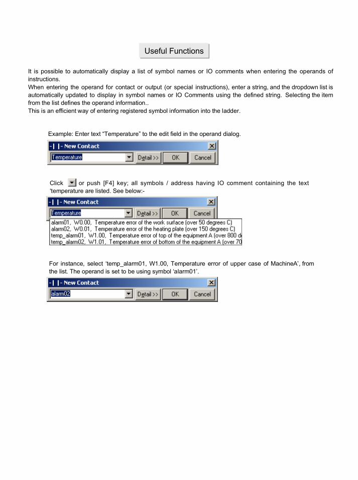
It is possible to automatically display a list of symbol names or IO comments when entering the operands ofinstructions.When entering the operand for contact or output (or special instructions), enter a string, and the dropdown list isautomatically updated to display in symbol names or IO Comments using the defined string. Selecting the itemfrom the list defines the operand information..This is an efficient way of entering registered symbol information into the ladder.
Example: Enter text “Temperature” to the edit field in the operand dialog.
Click or push [F4] key; all symbols / address having IO comment containing the text‘temperature are listed. See below:-
For instance, select ‘temp_alarm01, W1.00, Temperature error of upper case of MachineA’, fromthe list. The operand is set to be using symbol ‘alarm01’.
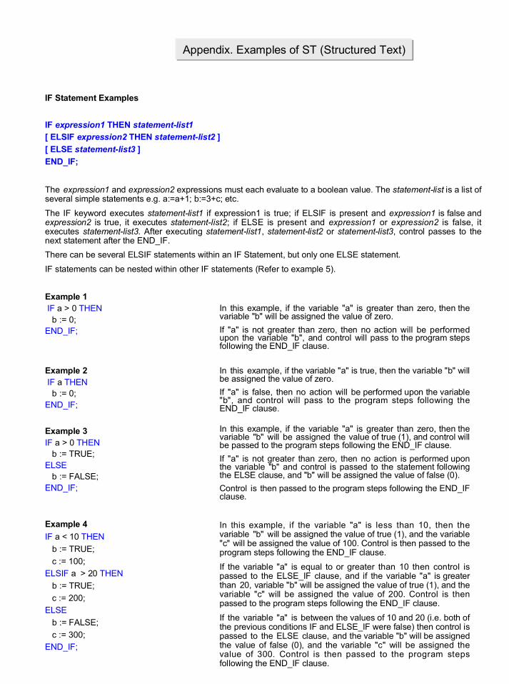
IF Statement Examples
IF expression1 THEN statement-list1[ ELSIF expression2 THEN statement-list2 ]
[ ELSE statement-list3 ]
END_IF;
The expression1 and expression2 expressions must each evaluate to a boolean value. The statement-list is a list ofseveral simple statements e.g. a:=a+1; b:=3+c; etc.
The IF keyword executes statement-list1 if expression1 is true; if ELSIF is present and expression1 is false andexpression2 is true, it executes statement-list2; if ELSE is present and expression1 or expression2 is false, itexecutes statement-list3. After executing statement-list1, statement-list2 or statement-list3, control passes to thenext statement after the END_IF.
There can be several ELSIF statements within an IF Statement, but only one ELSE statement.
IF statements can be nested within other IF statements (Refer to example 5).
Example 1 IF a > 0 THEN b := 0;END_IF;
Example 2 IF a THEN b := 0;END_IF;
Example 3IF a > 0 THEN b := TRUE;ELSE b := FALSE;END_IF;
Example 4
IF a < 10 THEN
b := TRUE;
c := 100;ELSIF a > 20 THEN
b := TRUE;
c := 200;ELSE
b := FALSE;
c := 300;END_IF;
Appendix. Examples of ST (Structured Text)
In this example, if the variable "a" is greater than zero, then thevariable "b" will be assigned the value of zero.
If "a" is not greater than zero, then no action will be performedupon the variable "b", and control will pass to the program stepsfollowing the END_IF clause.
In this example, if the variable "a" is true, then the variable "b" willbe assigned the value of zero.
If "a" is false, then no action will be performed upon the variable"b", and control will pass to the program steps following theEND_IF clause.
In this example, if the variable "a" is greater than zero, then thevariable "b" will be assigned the value of true (1), and control willbe passed to the program steps following the END_IF clause.
If "a" is not greater than zero, then no action is performed uponthe variable "b" and control is passed to the statement followingthe ELSE clause, and "b" will be assigned the value of false (0).
Control is then passed to the program steps following the END_IFclause.
In this example, if the variable "a" is less than 10, then thevariable "b" will be assigned the value of true (1), and the variable"c" will be assigned the value of 100. Control is then passed to theprogram steps following the END_IF clause.
If the variable "a" is equal to or greater than 10 then control ispassed to the ELSE_IF clause, and if the variable "a" is greaterthan 20, variable "b" will be assigned the value of true (1), and thevariable "c" will be assigned the value of 200. Control is thenpassed to the program steps following the END_IF clause.
If the variable "a" is between the values of 10 and 20 (i.e. both ofthe previous conditions IF and ELSE_IF were false) then control ispassed to the ELSE clause, and the variable "b" will be assignedthe value of false (0), and the variable "c" will be assigned thevalue of 300. Control is then passed to the program stepsfollowing the END_IF clause.

IF Statement Examples
Example 5
IF a THEN
b := TRUE;ELSE
IF c>0 THEN
d := 0; ELSE
d := 100;
END_IF; d := 400;
END_IF;
WHILE Statement Examples
WHILE expression DO statement-list;
END_WHILE;
The WHILE expression must evaluate to a boolean value. The statement-list is a list of several simple statements.
The WHILE keyword repeatedly executes the statement-list while the expression is true. When the expressionbecomes false, control passes to the next statement after the END_WHILE.
Example 1
WHILE a < 10 DO a := a + 1;
b := b * 2.0;
END_WHILE;
Example 2
WHILE a DO
b := b + 1; IF b > 10 THEN
a:= FALSE; END_IF;
END_WHILE;
Example 3
WHILE (a + 1) >= (b * 2) DO a := a + 1;
b := b / c;
END_WHILE;
In this example (an example of a nested IF .. THENstatement), if the variable "a" is true (1), then the variable "b"will be assigned the value of true (1), and control will bepassed to the program steps following the associatedEND_IF clause.
If "a" is false (0), then no action is performed upon thevariable "b" and control is passed to the statement followingthe ELSE clause (in this example, another IF .. THENstatement, which is executed as described in Example 3,although it should be noted that any of the supportedIEC61131-3 statements may be used).
After the described IF .. THEN statement is executed, thevariable "d" will be assigned the value of 400.
Control is then passed to the program steps following theEND_IF clause.
In this example, the WHILE expression will be evaluated andif true (i.e. variable "a" is less than 10) then the statement-list(a:=a+1; and b:=b*2.0;) will be executed. After execution ofthe statement-list, control will pass back to the start of theWHILE expression. This process is repeated while variable"a" is less than 10. When the variable "a" is greater than orequal to 10, then the statement-list will not be executed andcontrol will pass to the program steps following theEND_WHILE clause.
In this example, the WHILE expression will be evaluated andif true (i.e. variable "a" is true), then the statement-list (b:=b+1;and the IF .. THEN statement) will be executed. Afterexecution of the statement-list, control will pass back to thestart of the WHILE expression. This process is repeated whilevariable "a" is true. When variable "a" is false, the statement-list will not be executed and control will pass to the programsteps following the END_WHILE clause.
In this example, the WHILE expression will be evaluated andif true (i.e. variable "a" plus 1 is greater than or equal tovariable "b" multiplied by 2) then the statement-list (a:=a+1;and b:=b/c;) will be executed. After execution of thestatement-list, control will pass back to the start of the WHILEexpression. This process is repeated while the WHILEexpression equates to true. When the WHILE expression isfalse, then the statement-list will not be executed and controlwill pass to the program steps following the END_WHILEclause.

WHILE Statement Examples
Example 4
WHILE (a - b) <= (b + c) DO
a := a + 1; b := b * a;
END_WHILE;
REPEAT Statement Examples
REPEAT statement-list;
UNTIL expression
END_REPEAT;
The REPEAT expression must evaluate to a boolean value. The statement-list is a list of several simple statements.
The REPEAT keyword repeatedly executes the statement-list while the expression is false. When the expressionbecomes true, control passes to the next statement after END_REPEAT.
Example 1
REPEAT a := a + 1;
b := b * 2.0;
UNTIL a > 10END_REPEAT;
Example 2
REPEAT
b := b + 1; IF b > 10 THEN
a:= FALSE;
END_IF;UNTIL a
END_REPEAT;
Example 3
REPEAT
a := a + 1;
b := b / c;
UNTIL (a + 1) >= (b * 2)END_REPEAT;
Example 4
REPEAT
a := a + 1;
b := b * a;
UNTIL (a - b) <= (b + c)END_REPEAT;
In this example, the WHILE expression will be evaluated and iftrue (i.e. variable "a" minus variable "b" is less than or equal tovariable "b" plus variable "c") then the statement-list (a:=a+1; andb:=b*a;) will be executed. After execution of the statement-list,control will pass back to the start of the WHILE expression. Thisprocess is repeated while the WHILE expression is true. Whenthe WHILE expression is false, then the statement-list will not beexecuted and control will pass to the program steps following theEND_WHILE clause.
In this example, the statement-list (a:=a+1; and b:=b*2.0;) will beexecuted. After execution of the statement-list the UNTIL expressionis evaluated and if false (i.e. variable "a" is less than or equal to 10),then control will pass back to the start of the REPEAT expression andthe statement-list will be executed again. This process is repeatedwhile the UNTIL expression equates to false. When the UNTILexpression equates to true (i.e. variable "a" is greater than 10) thencontrol will pass to the program steps following the END_REPEATclause.
In this example, the statement-list (b:=b+1; and the IF .. THENstatement) will be executed. After execution of the statement-list theUNTIL expression is evaluated and if false (i.e. variable "a" is false),then control will pass back to the start of the REPEAT expression andthe statement-list will be executed again. This process is repeatedwhile the UNTIL expression equates to false. When the UNTILexpression equates to true (i.e. variable "a" is true) then control willpass to the program steps following the END_REPEAT clause.
In this example, the statement-list (a:=a+1; and b:=b/c;) will beexecuted. After execution of the statement-list the UNTIL expressionis evaluated and if false (i.e. variable "a" plus 1 is less than variable"b" multiplied by 2) then control will pass back to the start of theREPEAT expression and the statement-list will be executed again.This process is repeated while the UNTIL expression equates to false.When the UNTIL expression equates to true (i.e. variable "a" plus 1 isgreater than or equal to variable "b" multiplied by 2) then control willpass to the program steps following the END_REPEAT clause.
In this example, the statement-list (a:=a+1; and b:=b*a;) will beexecuted. After execution of the statement-list the UNTIL expressionis evaluated and if false (i.e. variable "a" minus variable "b" is greaterthan variable "b" plus variable "c"), then control will pass back to thestart of the REPEAT expression and the statement-list will beexecuted again. This process is repeated while the UNTIL expressionequates to false. When the UNTIL expression equates to true (i.e.variable "a" minus variable "b" is less than or equal to variable "b" plusvariable "c") then control will pass to the program steps following theEND_REPEAT clause.

FOR Statement Examples
FOR control variable := integer expression1 TO integer expression2 [ BY integer expression3 ] DO
statement-list;
END_FOR;
The FOR control variable must be of an integer variable type. The FOR integer expressions must evaluate to thesame integer variable type as the control variable. The statement-list is a list of several simple statements.
The FOR keyword repeatedly executes the statement-list while the control variable is within the range of integerexpression1 to integer expression2. If the BY is present then the control variable will be incremented by integerexpression3 otherwise by default it is incremented by one. The control variable is incremented after every executedcall of the statement-list. When the control variable is no longer in the range integer expression1 to integerexpression2, control passes to the next statement after the END_FOR.
FOR statements can be nested within other FOR statements.
Example 1
FOR a := 1 TO 10 DO
b := b + a;
END_FOR;
Example 2
FOR a := 1 TO 10 BY 2 DO
b := b + a; c := c + 1.0;
END_FOR;
Example 3
FOR a := 10 TO 1 BY -1 DO
b := b + a; c := c + 1.0;
END_FOR;
Example 4
FOR a := b + 1 TO c + 2 DO d := d + a;
e := e + 1;
END_FOR;
In this example, the FOR expression will initially be evaluated andvariable "a" will be initialized with the value 1. The value ofvariable "a" will then be compared with the 'TO' value of the FORstatement and if it is less than or equal to 10 then the statement-list (i.e. b:=b+a;) will be executed. Variable "a" will then beincremented by 1 and control will pass back to the start of theFOR statement. Variable "a" will again be compared with the 'TO'value and if it is less than or equal to 10 then the statement-listwill be executed again. This process is repeated until the value ofvariable "a" is greater than 10, and then control will pass to theprogram steps following the END_FOR clause.
In this example, the FOR expression will initially be evaluated andvariable "a" will be initialized with the value 1. The value ofvariable "a" will then be compared with the 'TO' value of the FORstatement and if it is less than or equal to 10 then the statement-list (i.e. b:=b+a; and c:=c+1.0;) will be executed. Variable "a" willthen be incremented by 2 and control will pass back to the start ofthe FOR statement. Variable "a" will again be compared with the'TO' value and if it is less than or equal to 10 then the statement-list will be executed again. This process is repeated until the valueof variable "a" is greater than 10, and then control will pass to theprogram steps following the END_FOR clause.
In this example, the FOR expression will initially be evaluated andvariable "a" will be initialized with the value 10. The value ofvariable "a" will then be compared with the 'TO' value of the FORstatement and if it is greater than or equal to 1 then the statement-list (i.e. b:=b+a; and c:=c+1.0;) will be executed. Variable "a" willthen be decremented by 1 and control will pass back to the startof the FOR statement. Variable "a" will again be compared withthe 'TO' value and if it is greater than or equal to 1 then thestatement-list will be executed again. This process is repeateduntil the value of variable "a" is less than 1, and then control willpass to the program steps following the END_FOR clause.
In this example, the FOR expression will initially be evaluated andvariable "a" will be initialized with the value of variable "b" plus 1.The 'TO' value of the FOR statement will be evaluated to thevalue of variable "c" plus 2. The value of variable "a" will then becompared with the 'TO' value and if it is less than or equal to itthen the statement-list (i.e. d:=d+a; and e:=e+1;) will be executed.Variable "a" will then be incremented by 1 and control will passback to the start of the FOR statement. Variable "a" will again becompared with the 'TO' value and if it is less than or equal to itthen the statement-list will be executed again. This process isrepeated until the value of variable "a" is greater than the 'TO'value, and then control will pass to the program steps followingthe END_FOR clause.

FOR Statement Examples
Example 5
FOR a := b + c TO d - e BY f DO
g := g + a; h := h + 1.0;
END_FOR;
CASE Statement Examples
CASE expression OF
case label1 [ , case label2 ] [ .. case label3 ] : statement-list1;[ ELSE
statement-list2 ]
END_CASE;
The CASE expression must evaluate to an integer value. The statement-list is a list of several simple statements.The case labels must be valid literal integer values e.g. 0, 1, +100, -2 etc..
The CASE keyword evaluates the expression and executes the relevant statement-list associated with a case labelwhose value matches the initial expression. Control then passes to the next statement after the END_CASE. If nomatch occurs within the previous case labels and an ELSE command is present the statement-list associated withthe ELSE keyword is executed. If the ELSE keyword is not present, control passes to the next statement after theEND_CASE.
There can be several different case labels statements (and associated statement-list) within a CASE statement butonly one ELSE statement.
The “,” operator is used to list multiple case labels associated with the same statement-list.
The “..” operator denotes a range case label. If the CASE expression is within that range then the associatedstatement-list is executed, e.g. case label of 1..10 : a:=a+1; would execute the a:=a+1 if the CASE expression isgreater or equal to 1 and less than 10.
Example 1
CASE a OF
2 : b := 1; 5 : c := 1.0;
END_CASE;
Example 2
CASE a + 2 OF
-2 : b := 1;
5 : c := 1.0;ELSE
d := 1.0;
END_CASE;
In this example, the FOR expression will initially be evaluated and variable "a"will be initialized with the value of variable "b" plus variable "c". The 'TO' valueof the FOR statement will be evaluated to the value of variable "d" minusvariable "e". The value of variable "a" will then be compared with the 'TO' value.If the value of variable "f" is positive and the value of variable "a" is less than orequal to the 'TO' value then the statement-list (i.e. g:=g+a; and h:=h+1.0;) willbe executed. If the value variable "f" is negative and the value of variable "a" isgreater than or equal to the 'TO' value then the statement-list (i.e. g:=g+a; andh:=h+1.0;) will also be executed. Variable "a" will then be incremented ordecremented by the value of variable "f" and control will pass back to the startof the FOR statement. Variable "a" will again be compared with the 'TO' valueand the statement-list executed if appropriate (as described above).
This process is repeated until the value of variable "a" is greater than the 'TO'value (if the value of variable "f" is positive) or until the value of variable "a" isless than the 'TO' value (if the value of variable "f" is negative), and thencontrol will pass to the program steps following the END_FOR clause.
In this example, the CASE statement will be evaluated and then compared witheach of the CASE statement comparison values (i.e. 2 and 5 in this example).
If the value of variable "a" is 2 then that statement-list will be executed (i.e. b:=1;).Control will then pass to the program steps following the END_CASE clause.
If the value of variable "a" is 5 then that statement-list will be executed (i.e. c:=1.0;).Control will then pass to the program steps following the END_CASE clause.
If the value of variable "a" does not match any of the CASE statement comparisonvalues then control will pass to the program steps following the END_CASE clause.
In this example, the CASE statement will be evaluated and then compared witheach of the CASE statement comparison values (i.e. -2 and 5 in this example).
If the value of variable "a" plus 2 is -2 then that statement-list will be executed (i.e.b:=1;). Control will then pass to the program steps following the END_CASE clause.If the value of variable "a" plus 2 is 5 then that statement-list will be executed (i.e.c:=1.0;). Control will then pass to the program steps following the END_CASEclause. If the value of variable "a" plus 2 is not -2 or 5, then the statement-list in theELSE condition (i.e. d:=1.0;) will be executed. Control will then pass to the programsteps following the END_CASE clause.

CASE Statement Examples
Example 3 CASE a + 3 * b OF 1, 3 : b := 2; 7, 11 : c := 3.0;ELSE d := 4.0;END_CASE;
Example 4 CASE a OF-2, 2, 4 : b := 2; c := 1.0;6..11, 13 : c := 2.0;1, 3, 5 : c := 3.0;ELSE b := 1; c := 4.0;END_CASE;
In this example, the CASE statement will be evaluated and thencompared with each of the CASE statement comparison values (i.e. 1or 3 and 7 or 11 in this example).
If the value of variable "a" plus 3 multiplied by variable "b" is 1 or 3,then that statement-list will be executed (i.e. b:=2;). Control will thenpass to the program steps following the END_CASE clause.
If the value of variable "a" plus 3 multiplied by variable "b" is 7 or 11,then that statement-list will be executed (i.e. c:=3.0;). Control will thenpass to the program steps following the END_CASE clause.
If the value of variable "a" plus 3 multiplied by variable "b" is not 1, 3,7 or 11, then the statement-list in the ELSE condition (i.e. d:=4.0;) willbe executed. Control will then pass to the program steps following theEND_CASE clause.
In this example, the CASE statement will be evaluated and thencompared with each of the CASE statement comparison values, i.e. (-2, 2 or 4) and (6 to 11 or 13) and (1, 3 or 5) in this example.
If the value of variable "a" equals -2, 2 or 4, then that statement-listwill be executed (i.e. b:=2; and c:=1.0;). Control will then pass to theprogram steps following the END_CASE clause.
If the value of variable "a" equals 6, 7, 8, 9, 10, 11 or 13 then, thatstatement-list will be executed (i.e. c:=2.0;). Control will then pass tothe program steps following the END_CASE clause.
If the value of variable "a" is 1, 3 or 5, then that statement-list will beexecuted (i.e. c:=3.0;). Control will then pass to the program stepsfollowing the END_CASE clause.
If the value of variable "a" is none of those above, then the statement-list in the ELSE condition (i.e. b:=1; and c:=4.0;) will be executed.Control will then pass to the program steps following the END_CASEclause.

EXIT Statement Examples
WHILE expression DO statement-list1; EXIT;END_WHILE;statement-list2;
REPEAT statement-list1; EXIT;UNTIL expressionEND_REPEAT;statement-list2; FOR control variable := integer expression1 TO integer expression2 [ BY integer expression3 ] DO statement-list1; EXIT;END_FOR;statement-list2;
The statement-list is a list of several simple statements.
The EXIT keyword discontinues the repetitive loop execution to go to the next statement, and can only be used inrepetitive statements (WHILE, REPEAT, FOR statements). When the EXIT keyword is executed after statement-list1 in the repetitive loop, the control passes to statement-list2 immediately.
Example 1
WHILE a DO IF c = TRUE THEN
b:=0;EXIT;
END_IF; IF b > 10 THEN
a:= FALSE; END_IF;
END_WHILE;
d:=1;
Example 2
a:=FALSE;
FOR i:=1 TO 20 DO
FOR j:=0 TO 9 DO IF i>=10 THEN
n:=i*10+j;
a:=TRUE;EXIT; END_IF;
END_FOR;
IF a THEN EXIT; END_IF;END_FOR;
d:=1;
If the first IF expression is true (i.e. variable "c" is true), thestatement-list (b:=0; and EXIT;) is executed during theexecution of the WHILE loop. After the execution of the EXITkeyword, the WHILE loop is discontinued and the controlpasses to the next statement (d:=1;) after the END_WHILEclause.
If the first IF expression is true (i.e. i>=10 is true) in the insideFOR loop, the statement-list (n:=i*10+j; and a:=TRUE; andEXIT;) is executed during the execution of the FOR loop.After the execution of the EXIT keyword, the inside FOR loopis discontinued and the control passes to the next IFstatement after the END_FOR clause. If this IF expression istrue (i.e. the variable "a" is true), EXIT keyword is executed ,the outside FOR loop is discontinued after END_FOR clause,and the control passes to the next statement (d:=1;).

RETURN Statement Examples
statement-list1;RETURN;
statement-list2;
The statement-list is a list of several simple statements.
The RETURN keyword breaks off the execution of the inside of the Function Block after statement-list1, and thenthe control returns to the program which calls the Function Block without executing statement-list2.
Example 1
IF a_1*b>100 THEN
c:=TRUE;RETURN;END_IF;
IF a_2*(b+10)>100 THEN
c:=TRUE;RETURN;END_IF;
IF a_3*(b+20)>100 THEN
c:=TRUE;END_IF;
Array Examples
variable name [subscript index]
An array is a collection of like variables. The size of an array can be defined in the Function Block variable table.
An individual variable can be accessed using the array subscript operator [ ].
The subscript index allows a specific variable within an array to be accessed. The subscript index must be either apositive literal value, an integer expression or an integer variable. The subscript index is zero based. A subscriptindex value of zero would access the first variable, a subscript index value of one would access the second variableand so on.
Warning
If the subscript index is either an integer expression or integer variable, you must ensure that the resultingsubscript index value is within the valid index range of the array. Accessing an array with an invalid indexmust be avoided. Refer to Example 5 for details of how to write safer code when using variable arrayoffsets.
Example 1
a[0] := 1;
a[1] := -2;a[2] : = 1+2;
a[3] : = b;
a[4] : = b+1;
Example 2
c[0] := FALSE;
c[1] := 2>3;
If the first or second IF statement is true (i.e. "a_1*b" is largerthan 100, or "a_2*(b+10)" is larger than 100), the statement(c:=TRUE; and RETURN;) is executed. The execution of theRETURN keyword breaks off the execution of the inside ofthe Function Block and the control returns to the programwhich calls the Function Block.
In this example variable "a" is an array of 5 elements and hasan INT data type. Variable "b" also has an INT data type.When executed, the first element in the array will be set to thevalue 1, the second element will be set to -2, the thirdelement will be set to 3 (i.e. 1+2), the forth element will be setto the value of variable "b" and the fifth element will be set tothe value of variable "b" plus 1.
In this example variable "c" is an array of 2 elements and hasa BOOL data type. When executed, the first element in thearray will be set to false and the second element will be set tofalse (i.e. 2 is greater than 3 evaluates to false).

Array Examples
Example 3
d[9]:= 2.0;
Example 4
a[1] := b[2];
Example 5
a[b] := 1;
a[b+1] := 1;a[(b+c) *( d-e)] := 1;
Note: As the integer variables and expressions are being used to access the array, the actual index valuewill not be known until run time, so the user must ensure that the index is within the valid range of thearray a. For example, a safer way would be to check the array index is valid:
f := (b+c) *( d-e);
IF (f >0) AND (f<5) THEN
a[f] := 1;END_IF;
Where variable "f" has an INT data type.
Example 6
a[b[1]]:= c;
a[b[2] + 3]:= c;
In this example, variable "d" is an array of 10 elements andhas a REAL data type. When executed, the last element inthe array (the 10th element) will be set to 2.0.
In this example, variable "a" and variable "b" are arrays of thesame data type. When executed, the value of the secondelement in variable "a" will be set to the value of the thirdelement in variable "b".
This example shows how an array element expression can beused within another array element expression.
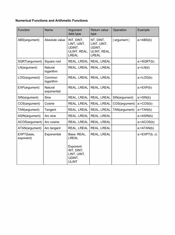
Function Name Argument data type
Return value type
Operation Example
ABS(argument) Absolute value INT, DINT, LINT, UINT, UDINT, ULINT, REAL, LREAL
NT, DINT, LINT, UINT, UDINT, ULINT, REAL, LREAL
| argument |
a:=ABS(b)
SQRT(argument) Square root REAL, LREAL REAL, LREAL a:=SQRT(b)
LN(argument) Natural logarithm
REAL, LREAL REAL, LREAL a:=LN(b)
LOG(argument) Common logarithm
REAL, LREAL REAL, LREAL a:=LOG(b)
EXP(argument) Natural exponential
REAL, LREAL REAL, LREAL a:=EXP(b)
SIN(argument) Sine REAL, LREAL REAL, LREAL SIN(argument) a:=SIN(b)
COS(argument) Cosine REAL, LREAL REAL, LREAL COS(argument) a:=COS(b)
TAN(argument) Tangent REAL, LREAL REAL, LREAL TAN(argument) a:=TAN(b)
ASIN(argument) Arc sine REAL, LREAL REAL, LREAL a:=ASIN(b)
ACOS(argument) Arc cosine REAL, LREAL REAL, LREAL a:=ACOS(b)
ATAN(argument) Arc tangent REAL, LREAL REAL, LREAL a:=ATAN(b)
EXPT(base, exponent)
Exponential Base: REAL, LREAL
Exponent: INT, DINT, LINT, UINT, UDINT, ULINT
REAL, LREAL a:=EXPT(b, c)
Numerical Functions and Arithmetic Functions

Certain Terms and Conditions of Sale1. Offer; Acceptance. These terms and conditions (these "Terms") are deemed
part of all catalogs, manuals or other documents, whether electronic or in writ-ing, relating to the sale of goods or services (collectively, the "Goods") byOmron Electronics LLC and its subsidiary companies ("Seller"). Seller herebyobjects to any terms or conditions proposed in Buyer's purchase order or otherdocuments which are inconsistent with, or in addition to, these Terms. Pleasecontact your Omron representative to confirm any additional terms for salesfrom your Omron company.
2. Prices. All prices stated are current, subject to change without notice bySeller. Buyer agrees to pay the price in effect at time of shipment.
3. Discounts. Cash discounts, if any, will apply only on the net amount ofinvoices sent to Buyer after deducting transportation charges, taxes andduties, and will be allowed only if (i) the invoice is paid according to Seller'spayment terms and (ii) Buyer has no past due amounts owing to Seller.
4. Orders. Seller will accept no order less than $200 net billing. 5. Governmental Approvals. Buyer shall be responsible for, and shall bear all
costs involved in, obtaining any government approvals required for the impor-tation or sale of the Goods.
6. Taxes. All taxes, duties and other governmental charges (other than generalreal property and income taxes), including any interest or penalties thereon,imposed directly or indirectly on Seller or required to be collected directly orindirectly by Seller for the manufacture, production, sale, delivery, importation,consumption or use of the Goods sold hereunder (including customs dutiesand sales, excise, use, turnover and license taxes) shall be charged to andremitted by Buyer to Seller.
7. Financial. If the financial position of Buyer at any time becomes unsatisfactoryto Seller, Seller reserves the right to stop shipments or require satisfactorysecurity or payment in advance. If Buyer fails to make payment or otherwisecomply with these Terms or any related agreement, Seller may (without liabilityand in addition to other remedies) cancel any unshipped portion of Goods soldhereunder and stop any Goods in transit until Buyer pays all amounts, includ-ing amounts payable hereunder, whether or not then due, which are owing to itby Buyer. Buyer shall in any event remain liable for all unpaid accounts.
8. Cancellation; Etc. Orders are not subject to rescheduling or cancellationunless Buyer indemnifies Seller fully against all costs or expenses arising inconnection therewith.
9. Force Majeure. Seller shall not be liable for any delay or failure in deliveryresulting from causes beyond its control, including earthquakes, fires, floods,strikes or other labor disputes, shortage of labor or materials, accidents tomachinery, acts of sabotage, riots, delay in or lack of transportation or therequirements of any government authority.
10. Shipping; Delivery. Unless otherwise expressly agreed in writing by Seller:a. Shipments shall be by a carrier selected by Seller;b. Such carrier shall act as the agent of Buyer and delivery to such carrier
shall constitute delivery to Buyer;c. All sales and shipments of Goods shall be FOB shipping point (unless oth-
erwise stated in writing by Seller), at which point title to and all risk of loss ofthe Goods shall pass from Seller to Buyer, provided that Seller shall retain asecurity interest in the Goods until the full purchase price is paid by Buyer;
d. Delivery and shipping dates are estimates only. e. Seller will package Goods as it deems proper for protection against normal
handling and extra charges apply to special conditions.11. Claims. Any claim by Buyer against Seller for shortage or damage to the
Goods occurring before delivery to the carrier must be presented in writing toSeller within 30 days of receipt of shipment and include the original transporta-tion bill signed by the carrier noting that the carrier received the Goods fromSeller in the condition claimed.
12. Warranties. (a) Exclusive Warranty. Seller's exclusive warranty is that theGoods will be free from defects in materials and workmanship for a period oftwelve months from the date of sale by Seller (or such other period expressedin writing by Seller). Seller disclaims all other warranties, express or implied.(b) Limitations. SELLER MAKES NO WARRANTY OR REPRESENTATION,EXPRESS OR IMPLIED, ABOUT NON-INFRINGEMENT, MERCHANTABIL-ITY OR FITNESS FOR A PARTICULAR PURPOSE OF THE GOODS.BUYER ACKNOWLEDGES THAT IT ALONE HAS DETERMINED THAT THEGOODS WILL SUITABLY MEET THE REQUIREMENTS OF THEIRINTENDED USE. Seller further disclaims all warranties and responsibility ofany type for claims or expenses based on infringement by the Goods or other-wise of any intellectual property right. (c) Buyer Remedy. Seller's sole obliga-tion hereunder shall be to replace (in the form originally shipped with Buyerresponsible for labor charges for removal or replacement thereof) the non-complying Good or, at Seller's election, to repay or credit Buyer an amountequal to the purchase price of the Good; provided that in no event shall Sellerbe responsible for warranty, repair, indemnity or any other claims or expensesregarding the Goods unless Seller's analysis confirms that the Goods wereproperly handled, stored, installed and maintained and not subject to contami-nation, abuse, misuse or inappropriate modification. Return of any goods byBuyer must be approved in writing by Seller before shipment. Seller shall notbe liable for the suitability or unsuitability or the results from the use of Goodsin combination with any electrical or electronic components, circuits, systemassemblies or any other materials or substances or environments. Anyadvice, recommendations or information given orally or in writing, are not to beconstrued as an amendment or addition to the above warranty.
13. Damage Limits; Etc. SELLER SHALL NOT BE LIABLE FOR SPECIAL, INDI-RECT OR CONSEQUENTIAL DAMAGES, LOSS OF PROFITS OR PRODUC-TION OR COMMERCIAL LOSS IN ANY WAY CONNECTED WITH THEGOODS, WHETHER SUCH CLAIM IS BASED IN CONTRACT, WARRANTY,NEGLIGENCE OR STRICT LIABILITY. Further, in no event shall liability ofSeller exceed the individual price of the Good on which liability is asserted.
14. Indemnities. Buyer shall indemnify and hold harmless Seller, its affiliates andits employees from and against all liabilities, losses, claims, costs andexpenses (including attorney's fees and expenses) related to any claim, inves-tigation, litigation or proceeding (whether or not Seller is a party) which arisesor is alleged to arise from Buyer's acts or omissions under these Terms or inany way with respect to the Goods. Without limiting the foregoing, Buyer (atits own expense) shall indemnify and hold harmless Seller and defend or settleany action brought against Seller to the extent that it is based on a claim thatany Good made to Buyer specifications infringed intellectual property rights ofanother party.
15. Property; Confidentiality. The intellectual property embodied in the Goods isthe exclusive property of Seller and its affiliates and Buyer shall not attempt toduplicate it in any way without the written permission of Seller. Notwithstand-ing any charges to Buyer for engineering or tooling, all engineering and toolingshall remain the exclusive property of Seller. All information and materialssupplied by Seller to Buyer relating to the Goods are confidential and propri-etary, and Buyer shall limit distribution thereof to its trusted employees andstrictly prevent disclosure to any third party.
16. Miscellaneous. (a) Waiver. No failure or delay by Seller in exercising any rightand no course of dealing between Buyer and Seller shall operate as a waiverof rights by Seller. (b) Assignment. Buyer may not assign its rights hereunderwithout Seller's written consent. (c) Amendment. These Terms constitute theentire agreement between Buyer and Seller relating to the Goods, and no pro-vision may be changed or waived unless in writing signed by the parties. (d) Severability. If any provision hereof is rendered ineffective or invalid, suchprovision shall not invalidate any other provision. (e) Setoff. Buyer shall haveno right to set off any amounts against the amount owing in respect of thisinvoice. (f) As used herein, "including" means "including without limitation".
Certain Precautions on Specifications and Use1. Suitability of Use. Seller shall not be responsible for conformity with any stan-
dards, codes or regulations which apply to the combination of the Good in theBuyer's application or use of the Good. At Buyer's request, Seller will provideapplicable third party certification documents identifying ratings and limitationsof use which apply to the Good. This information by itself is not sufficient for acomplete determination of the suitability of the Good in combination with theend product, machine, system, or other application or use. The following aresome examples of applications for which particular attention must be given.This is not intended to be an exhaustive list of all possible uses of this Good,nor is it intended to imply that the uses listed may be suitable for this Good: (i) Outdoor use, uses involving potential chemical contamination or electrical
interference, or conditions or uses not described in this document. (ii) Energy control systems, combustion systems, railroad systems, aviation
systems, medical equipment, amusement machines, vehicles, safety equipment, and installations subject to separate industry or governmentregulations.
(iii) Systems, machines and equipment that could present a risk to life orproperty. Please know and observe all prohibitions of use applicable tothis Good.
NEVER USE THE PRODUCT FOR AN APPLICATION INVOLVING SERIOUSRISK TO LIFE OR PROPERTY WITHOUT ENSURING THAT THE SYSTEMAS A WHOLE HAS BEEN DESIGNED TO ADDRESS THE RISKS, AND THATTHE SELLER'S PRODUCT IS PROPERLY RATED AND INSTALLED FORTHE INTENDED USE WITHIN THE OVERALL EQUIPMENT OR SYSTEM.
2. Programmable Products. Seller shall not be responsible for the user's pro-gramming of a programmable Good, or any consequence thereof.
3. Performance Data. Performance data given in this catalog is provided as aguide for the user in determining suitability and does not constitute a warranty.It may represent the result of Seller's test conditions, and the user must corre-late it to actual application requirements. Actual performance is subject to theSeller's Warranty and Limitations of Liability.
4. Change in Specifications. Product specifications and accessories may bechanged at any time based on improvements and other reasons. It is our prac-tice to change part numbers when published ratings or features are changed,or when significant construction changes are made. However, some specifica-tions of the Good may be changed without any notice. When in doubt, specialpart numbers may be assigned to fix or establish key specifications for yourapplication. Please consult with your Seller's representative at any time to con-firm actual specifications of purchased Good.
5. Errors and Omissions. The information in this catalog has been carefullychecked and is believed to be accurate; however, no responsibility is assumedfor clerical, typographical or proofreading errors, or omissions.

R133-E1-01 4/04 ©2005 OMRON ELECTRONICS LLC Specifications subject to change without notice.Printed in the U.S.A.
OMRON ELECTRONICS LLC
1 Commerce DriveSchaumburg, IL 60173847.843.7900For US technical support or other inquiries: 800.556.6766
OMRON CANADA, INC.885 Milner AvenueToronto, Ontario M1B 5V8416.286.6465
OMRON ON-LINEGlobal - http://www.omron.comUSA -http://www.omron.com/oeiCanada -http://www.omron.ca