the broken promise of device tree -
TRANSCRIPT
Supporting 200 different expansionboards
The broken promise of device tree

DevicetreeFrom devicetree.org:
The Device Tree is a data structure for describing hardware. Rather than hard coding every detail of a device into an operating system, many aspect of the hardware can be described in a data structure that is passed to the operating system at boot time. The device tree is used both by Open Firmware, and in the standalone Flattened Device Tree (FDT) form.
Devicetree
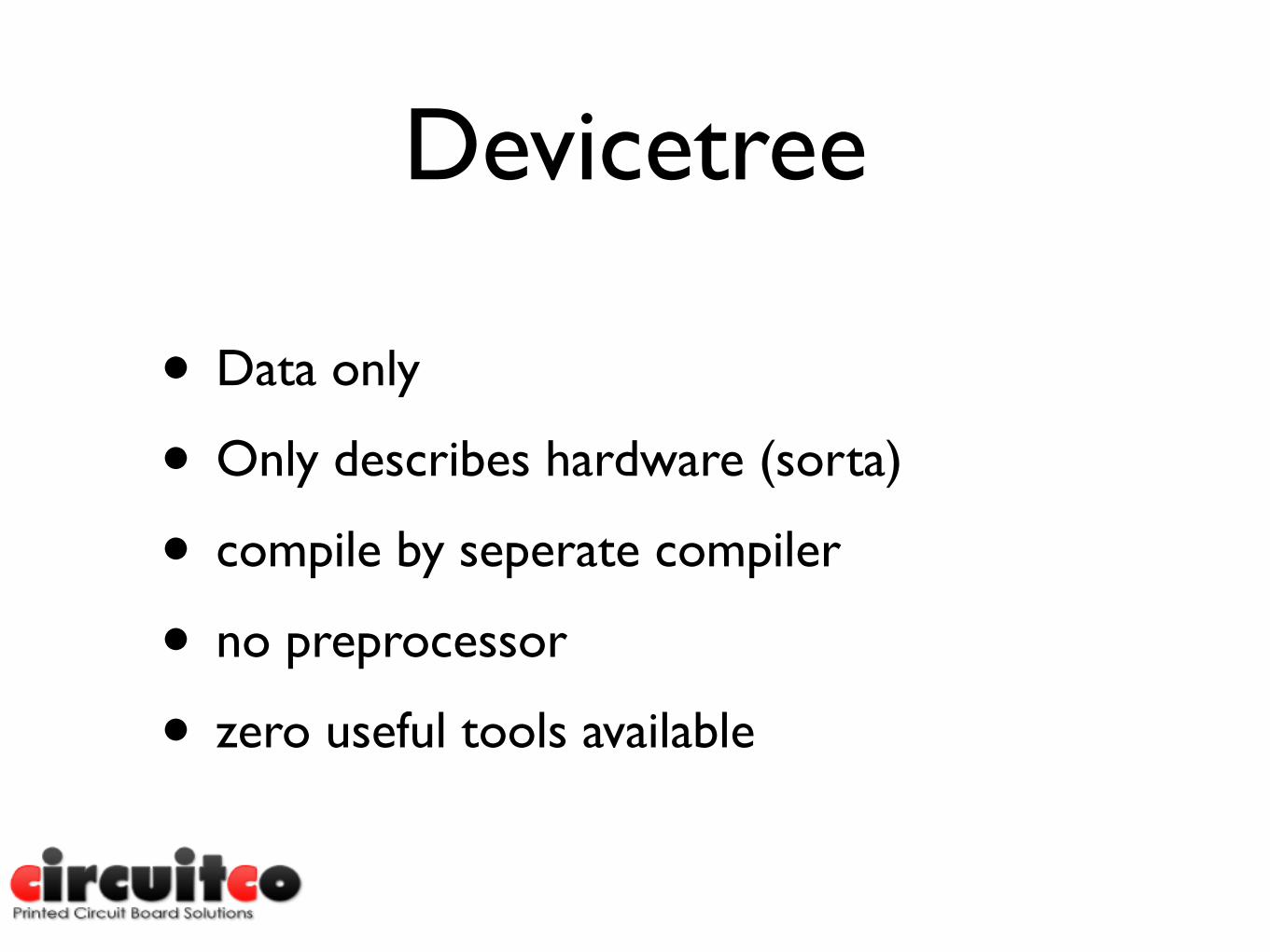
• Data only
• Only describes hardware (sorta)
• compile by seperate compiler
• no preprocessor
• zero useful tools available
Example
• Point browser to https://github.com/koenkooi/linux/blob/3.7-for-panto-rebase/arch/arm/boot/dts/am33xx.dtsi
Beaglebone overview

Beaglebone overview
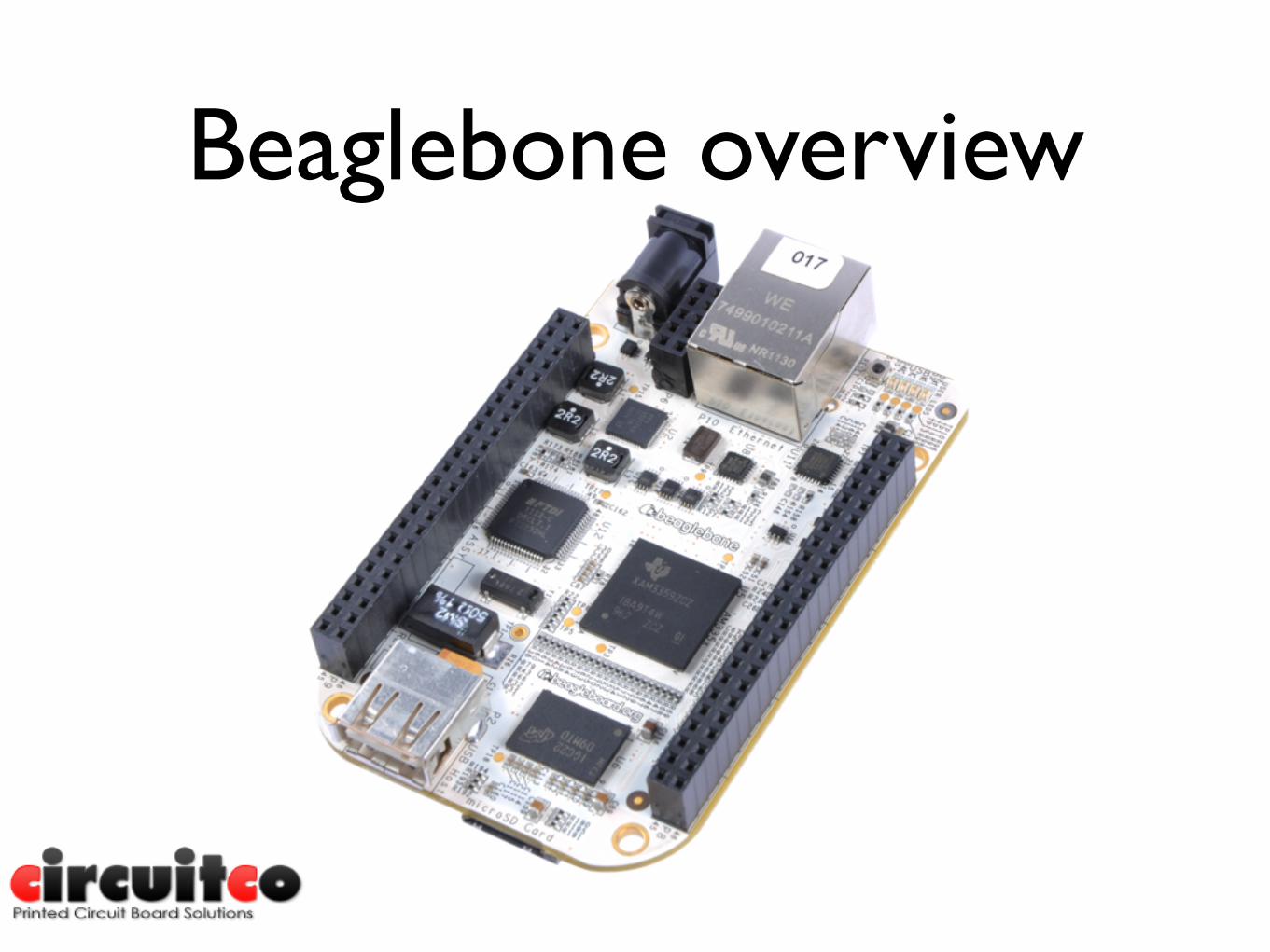
• Small, cheap board with a cortex A8 CPU
• 104 pins exposed on 3 expansion connectors
• Runs linux
• Targeted at people moving up from microcontroller based boards like the arduino

Capes
• Equivalent of ‘shields’ for arduino and ‘boosterpacks’ for msp430
• Standard allows up to 4 stacked capes
• EEPROM for ID and config info
Capes
• A lot of different types:
• Displays
• Wifi/Bluetooth/NFC/Radar
• Sensors
• CNC
• And a combination of the above

Weatherstation cape
I2C sensors
I2C EEPROM
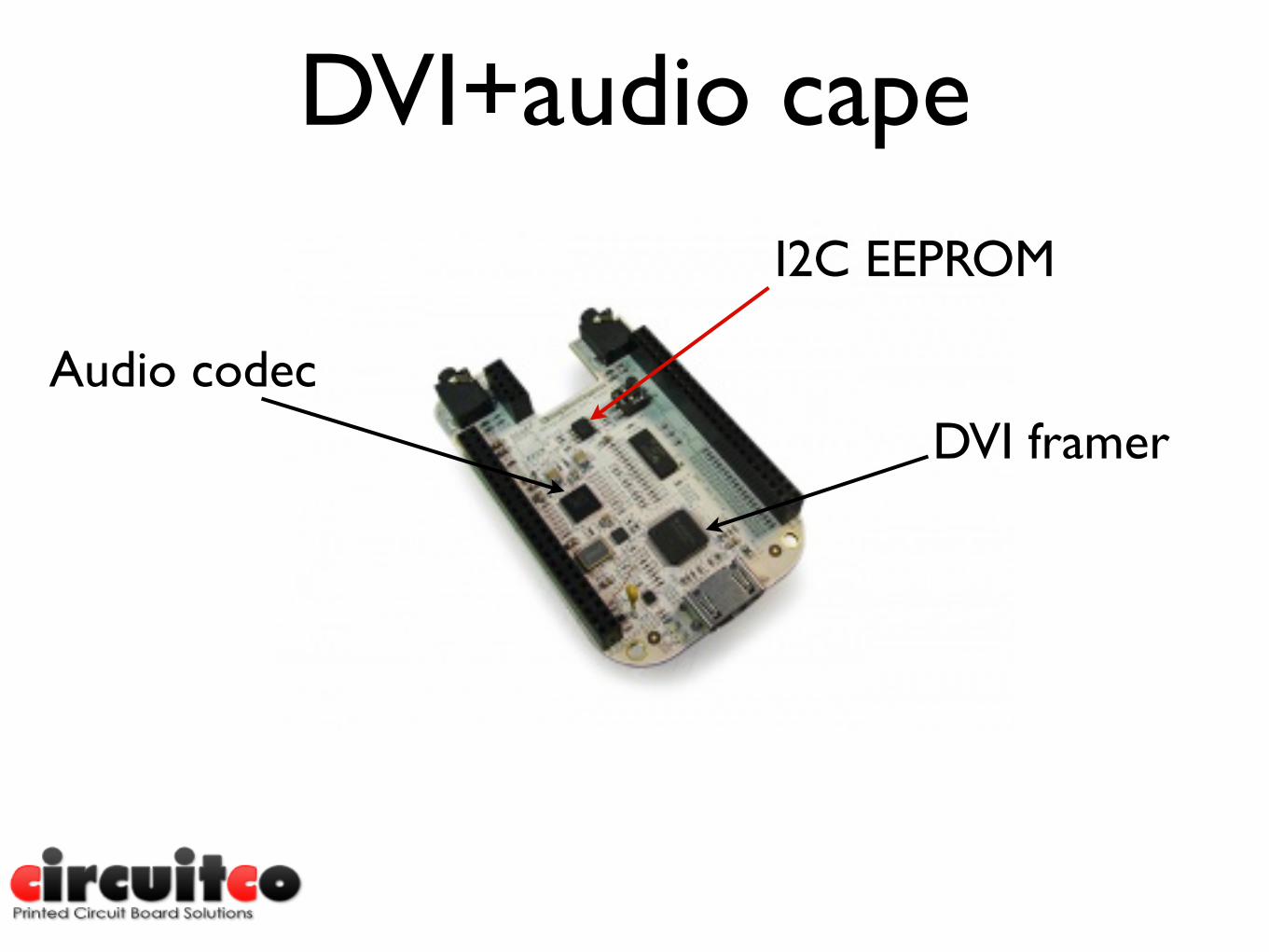
DVI+audio cape
I2C EEPROM
DVI framerAudio codec

BeBoPr capePWM
LED
Analog input
8 GPIO inputs
PRUss driven stepper motor drivers
I2C EEPROM(bottom)
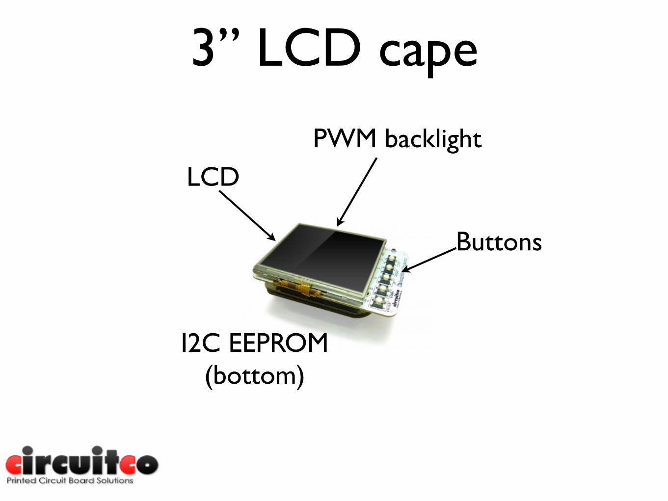
3” LCD cape
LCDPWM backlight
Buttons
I2C EEPROM(bottom)

Camera capeGPIO
GPMC bus
I2C EEPROM
Camera sensor
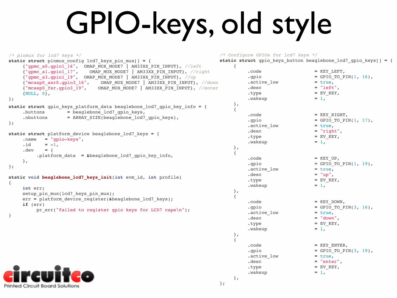
GPIO-keys, old style/* pinmux for lcd7 keys */static struct pinmux_config lcd7_keys_pin_mux[] = {! {"gpmc_a0.gpio1_16", OMAP_MUX_MODE7 | AM33XX_PIN_INPUT}, //left! {"gpmc_a1.gpio1_17", OMAP_MUX_MODE7 | AM33XX_PIN_INPUT}, //right! {"gpmc_a3.gpio1_19", OMAP_MUX_MODE7 | AM33XX_PIN_INPUT}, //up! {"mcasp0_axr0.gpio3_16", OMAP_MUX_MODE7 | AM33XX_PIN_INPUT}, //down! {"mcasp0_fsr.gpio3_19", OMAP_MUX_MODE7 | AM33XX_PIN_INPUT}, //enter! {NULL, 0},};
/* Configure GPIOs for lcd7 keys */static struct gpio_keys_button beaglebone_lcd7_gpio_keys[] = {! {! ! .code = KEY_LEFT,! ! .gpio = GPIO_TO_PIN(1, 16),! ! .active_low = true,! ! .desc = "left",! ! .type = EV_KEY,! ! .wakeup = 1,! },! {! ! .code = KEY_RIGHT,! ! .gpio = GPIO_TO_PIN(1, 17),! ! .active_low = true,! ! .desc = "right",! ! .type = EV_KEY,! ! .wakeup = 1,! },! {! ! .code = KEY_UP,! ! .gpio = GPIO_TO_PIN(1, 19),! ! .active_low = true,! ! .desc = "up",! ! .type = EV_KEY,! ! .wakeup = 1,! },! {! ! .code = KEY_DOWN,! ! .gpio = GPIO_TO_PIN(3, 16),! ! .active_low = true,! ! .desc = "down",! ! .type = EV_KEY,! ! .wakeup = 1,! },! {! ! .code = KEY_ENTER,! ! .gpio = GPIO_TO_PIN(3, 19),! ! .active_low = true,! ! .desc = "enter",! ! .type = EV_KEY,! ! .wakeup = 1,! },};
static struct gpio_keys_platform_data beaglebone_lcd7_gpio_key_info = {! .buttons = beaglebone_lcd7_gpio_keys,! .nbuttons = ARRAY_SIZE(beaglebone_lcd7_gpio_keys),};
static struct platform_device beaglebone_lcd7_keys = {! .name = "gpio-keys",! .id = -1,! .dev = {! ! .platform_data = &beaglebone_lcd7_gpio_key_info,! },};
static void beaglebone_lcd7_keys_init(int evm_id, int profile){! int err;! setup_pin_mux(lcd7_keys_pin_mux);! err = platform_device_register(&beaglebone_lcd7_keys);! if (err)! ! pr_err("failed to register gpio keys for LCD7 cape\n");}

GPIO-keys, DTgpio_keys {! ! ! compatible = "gpio-keys";! ! ! pinctrl-names = "default";! ! ! pinctrl-0 = <&bone_lcd3_cape_keys_00A0_pins>;
! ! ! #address-cells = <1>;! ! ! #size-cells = <0>;
! ! ! button@1 {! ! ! ! debounce_interval = <50>;! ! ! ! linux,code = <105>;! ! ! ! label = "left";! ! ! ! gpios = <&gpio2 16 0x0>;! ! ! ! gpio-key,wakeup;! ! ! ! autorepeat;! ! ! };! ! ! button@2 {! ! ! ! debounce_interval = <50>;! ! ! ! linux,code = <106>;! ! ! ! label = "right";! ! ! ! gpios = <&gpio2 17 0x0>;! ! ! ! gpio-key,wakeup;! ! ! ! autorepeat;! ! ! };! ! ! button@3 {! ! ! ! debounce_interval = <50>;! ! ! ! linux,code = <103>;! ! ! ! label = "up";! ! ! ! gpios = <&gpio4 19 0x0>;! ! ! ! gpio-key,wakeup;! ! ! ! autorepeat;! ! ! };! ! ! button@4 {! ! ! ! debounce_interval = <50>;! ! ! ! linux,code = <108>;! ! ! ! label = "down";! ! ! ! gpios = <&gpio2 28 0x0>;! ! ! ! gpio-key,wakeup;! ! ! ! autorepeat;! ! ! };! ! ! button@5 {! ! ! ! debounce_interval = <50>;! ! ! ! linux,code = <28>;! ! ! ! label = "enter";! ! ! ! gpios = <&gpio1 7 0x0>;! ! ! ! gpio-key,wakeup;! ! ! };! ! };
! ! bone_lcd3_cape_keys_00A0_pins: pinmux_bone_lcd3_cape_keys_00A0_pins {! ! ! pinctrl-single,pins = <! ! ! ! 0x040 0x2f! /* gpmc_a0.gpio1_16, INPUT | PULLDIS | MODE7 */! ! ! ! 0x044 0x2f! /* gpmc_a1.gpio1_17, INPUT | PULLDIS | MODE7 */! ! ! ! 0x1a4 0x2f! /* mcasp0_fsr.gpio3_19, INPUT | PULLDIS | MODE7 */! ! ! ! 0x078 0x2f! /* gpmc_ben1.gpio1_28, INPUT | PULLDIS | MODE7 */! ! ! ! 0x164 0x2f! /* ecap0_in_pwm0_out.gpio0_7, INPUT | PULLDIS | MODE7 */! ! ! >;! ! }
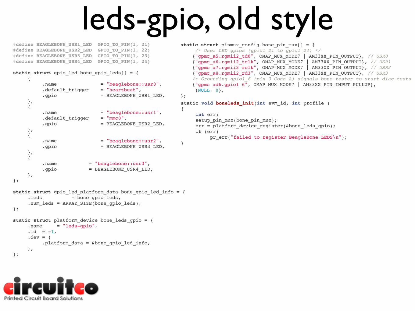
leds-gpio, old style#define BEAGLEBONE_USR1_LED GPIO_TO_PIN(1, 21)#define BEAGLEBONE_USR2_LED GPIO_TO_PIN(1, 22)#define BEAGLEBONE_USR3_LED GPIO_TO_PIN(1, 23)#define BEAGLEBONE_USR4_LED GPIO_TO_PIN(1, 24)
static struct gpio_led bone_gpio_leds[] = {! {! ! .name! ! ! = "beaglebone::usr0",! ! .default_trigger! = "heartbeat",! ! .gpio! ! ! = BEAGLEBONE_USR1_LED,! },! {! ! .name! ! ! = "beaglebone::usr1",! ! .default_trigger! = "mmc0",! ! .gpio! ! ! = BEAGLEBONE_USR2_LED,! },! {! ! .name! ! ! = "beaglebone::usr2",! ! .gpio! ! ! = BEAGLEBONE_USR3_LED,! },! {! ! .name = "beaglebone::usr3",! ! .gpio = BEAGLEBONE_USR4_LED,! },};
static struct gpio_led_platform_data bone_gpio_led_info = {! .leds! ! = bone_gpio_leds,! .num_leds!= ARRAY_SIZE(bone_gpio_leds),};
static struct platform_device bone_leds_gpio = {! .name! = "leds-gpio",! .id! = -1,! .dev!= {! ! .platform_data!= &bone_gpio_led_info,! },};
static struct pinmux_config bone_pin_mux[] = {! /* User LED gpios (gpio1_21 to gpio1_24) */ {"gpmc_a5.rgmii2_td0", OMAP_MUX_MODE7 | AM33XX_PIN_OUTPUT}, // USR0 {"gpmc_a6.rgmii2_tclk", OMAP_MUX_MODE7 | AM33XX_PIN_OUTPUT}, // USR1 {"gpmc_a7.rgmii2_rclk", OMAP_MUX_MODE7 | AM33XX_PIN_OUTPUT}, // USR2 {"gpmc_a8.rgmii2_rd3", OMAP_MUX_MODE7 | AM33XX_PIN_OUTPUT}, // USR3 /* Grounding gpio1_6 (pin 3 Conn A) signals bone tester to start diag tests */ {"gpmc_ad6.gpio1_6", OMAP_MUX_MODE7 | AM33XX_PIN_INPUT_PULLUP},! {NULL, 0},};
static void boneleds_init(int evm_id, int profile ){! int err;! setup_pin_mux(bone_pin_mux);! err = platform_device_register(&bone_leds_gpio);! if (err)! ! pr_err("failed to register BeagleBone LEDS\n");}

leds-gpio, DT! ! userled_pins: pinmux_userled_pins {! ! ! pinctrl-single,pins = <! ! ! ! 0x54 0x7! /* gpmc_a5.gpio1_21, OUTPUT | MODE7 */! ! ! ! 0x58 0x17!/* gpmc_a6.gpio1_22, OUTPUT_PULLUP | MODE7 */! ! ! ! 0x5c 0x7! /* gpmc_a7.gpio1_23, OUTPUT | MODE7 */! ! ! ! 0x60 0x17!/* gpmc_a8.gpio1_24, OUTPUT_PULLUP | MODE7 */! ! ! >;! ! };
! ! gpio-leds {! ! ! compatible = "gpio-leds";! ! ! pinctrl-names = "default";! ! ! pinctrl-0 = <&userled_pins>;
! ! ! led0 {! ! ! ! label = "beaglebone:green:usr0";! ! ! ! gpios = <&gpio2 21 0>;! ! ! ! linux,default-trigger = "heartbeat";! ! ! ! default-state = "off";! ! ! };
! ! ! led1 {! ! ! ! label = "beaglebone:green:usr1";! ! ! ! gpios = <&gpio2 22 0>;! ! ! ! linux,default-trigger = "mmc0";! ! ! ! default-state = "off";! ! ! };
! ! ! led2 {! ! ! ! label = "beaglebone:green:usr2";! ! ! ! gpios = <&gpio2 23 0>;! ! ! ! linux,default-trigger = "cpu0";! ! ! ! default-state = "off";! ! ! };
! ! ! led3 {! ! ! ! label = "beaglebone:green:usr3";! ! ! ! gpios = <&gpio2 24 0>;! ! ! ! default-state = "off";! ! ! };! ! };

Talking points
• pinctrl
• resource tracking
• evm/bone split
• uboot/uimage/dtb lockstep
• pdata only
• keycodes and other non-hardware bits
There's an if() in my boardfile, now what?