the benefits of using the mechanical toolset in autocad · the mechanical toolset (previously...
TRANSCRIPT

The Benefits of Using the Mechanical Toolset in AutoCAD®
A productivity study detailing the differences between AutoCAD® and the Mechanical toolset.
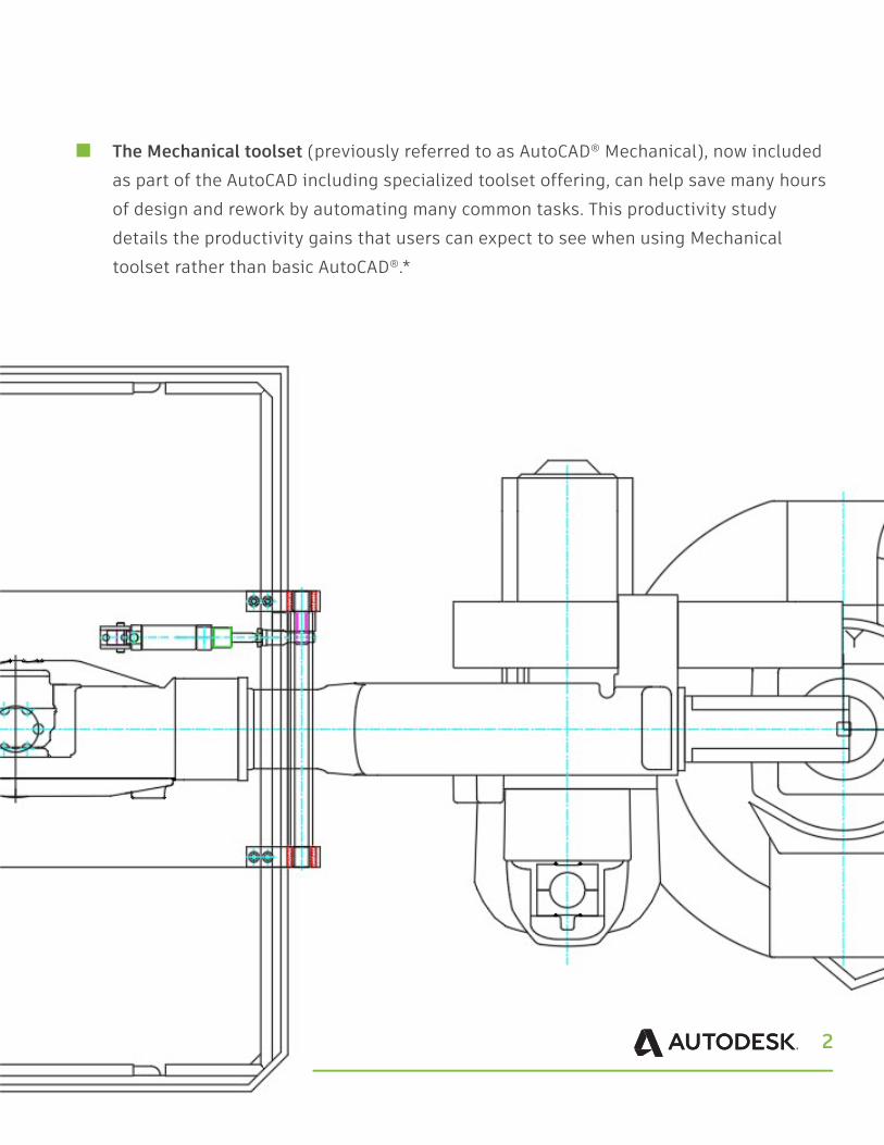
The Mechanical toolset (previously referred to as AutoCAD® Mechanical), now included as part of the AutoCAD including specialized toolset offering, can help save many hours of design and rework by automating many common tasks. This productivity study details the productivity gains that users can expect to see when using Mechanical toolset rather than basic AutoCAD®.*
2
3
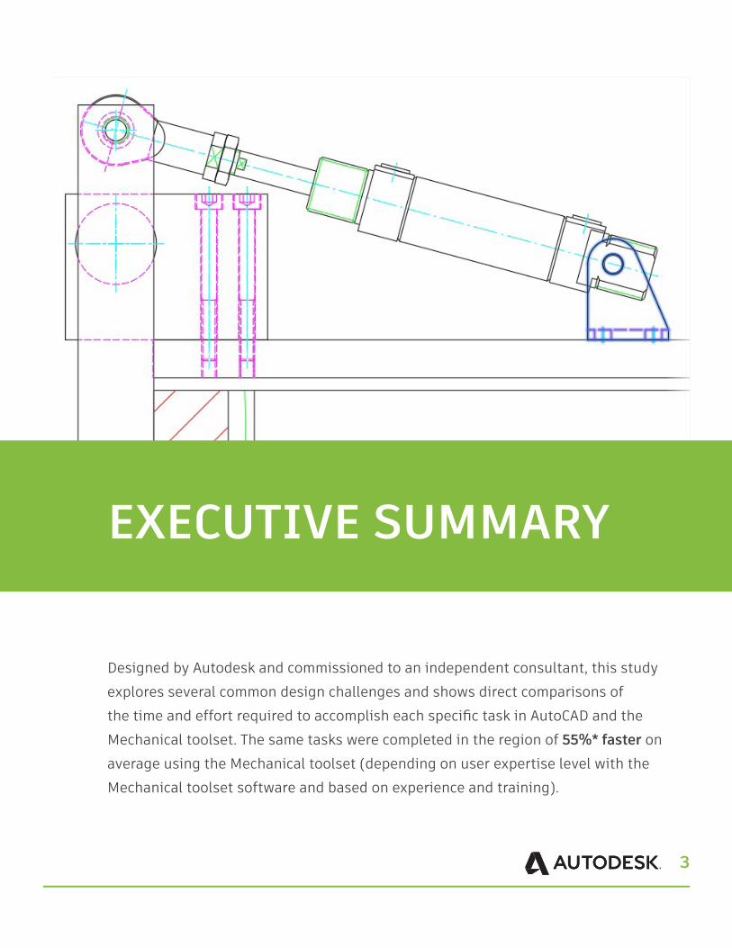
Designed by Autodesk and commissioned to an independent consultant, this study explores several common design challenges and shows direct comparisons of the time and effort required to accomplish each specific task in AutoCAD and the Mechanical toolset. The same tasks were completed in the region of 55%* faster on average using the Mechanical toolset (depending on user expertise level with the Mechanical toolset software and based on experience and training).
EXECUTIVE SUMMARY
4
For 2D CAD work, a total time reduction of approximately 55% is possible with the Mechanical toolset.
The risk of error is greatly reduced with more standardized functions and the availability of standardized parts.
KEY FINDINGS
5
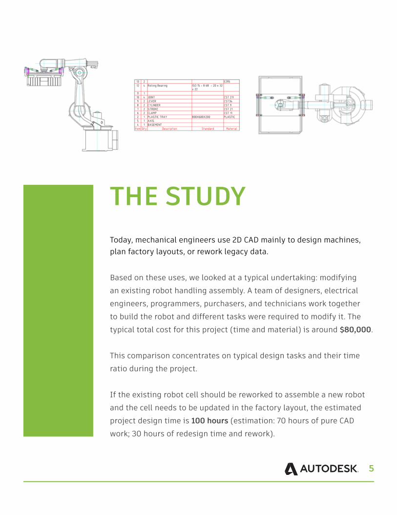
THE STUDYToday, mechanical engineers use 2D CAD mainly to design machines, plan factory layouts, or rework legacy data.
Based on these uses, we looked at a typical undertaking: modifying an existing robot handling assembly. A team of designers, electrical engineers, programmers, purchasers, and technicians work together to build the robot and different tasks were required to modify it. The typical total cost for this project (time and material) is around $80,000.
This comparison concentrates on typical design tasks and their time ratio during the project.
If the existing robot cell should be reworked to assemble a new robot and the cell needs to be updated in the factory layout, the estimated project design time is 100 hours (estimation: 70 hours of pure CAD work; 30 hours of redesign time and rework).
6
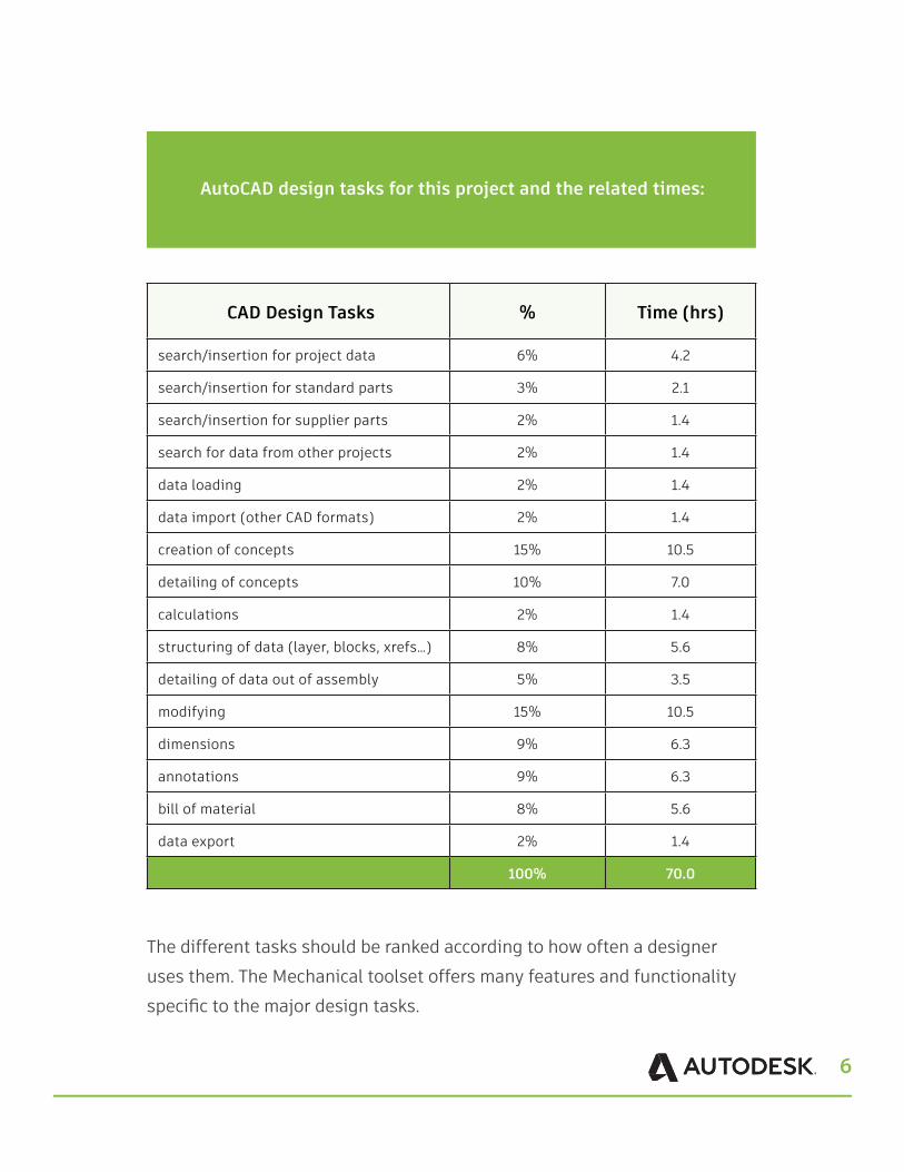
AutoCAD design tasks for this project and the related times:
The different tasks should be ranked according to how often a designer uses them. The Mechanical toolset offers many features and functionality specific to the major design tasks.
CAD Design Tasks % Time (hrs)
search/insertion for project data 6% 4.2
search/insertion for standard parts 3% 2.1
search/insertion for supplier parts 2% 1.4
search for data from other projects 2% 1.4
data loading 2% 1.4
data import (other CAD formats) 2% 1.4
creation of concepts 15% 10.5
detailing of concepts 10% 7.0
calculations 2% 1.4
structuring of data (layer, blocks, xrefs…) 8% 5.6
detailing of data out of assembly 5% 3.5
modifying 15% 10.5
dimensions 9% 6.3
annotations 9% 6.3
bill of material 8% 5.6
data export 2% 1.4
100% 70.0

7
Before we start, here are some things to note about the preconditions regarding this study:
A designer had to create the same results: one using basic AutoCAD and one using the Mechanical toolset. They reworked components of the existing robot handling assembly and updated the robot with this data. To have proper results, only the pure CAD work was measured, not the redesign needed. AutoCAD was compared against the Mechanical toolset.
We assumed that the AutoCAD user had already predefined templates with certain layer definitions, BOM structures, a basic library with standard parts, and other settings. The time to prepare all of this is not included in the comparison (even though the Mechanical toolset offers all of this out-of-the-box).
Now, let’s look at some of the tasks in detail before we evaluate the complete list.
8
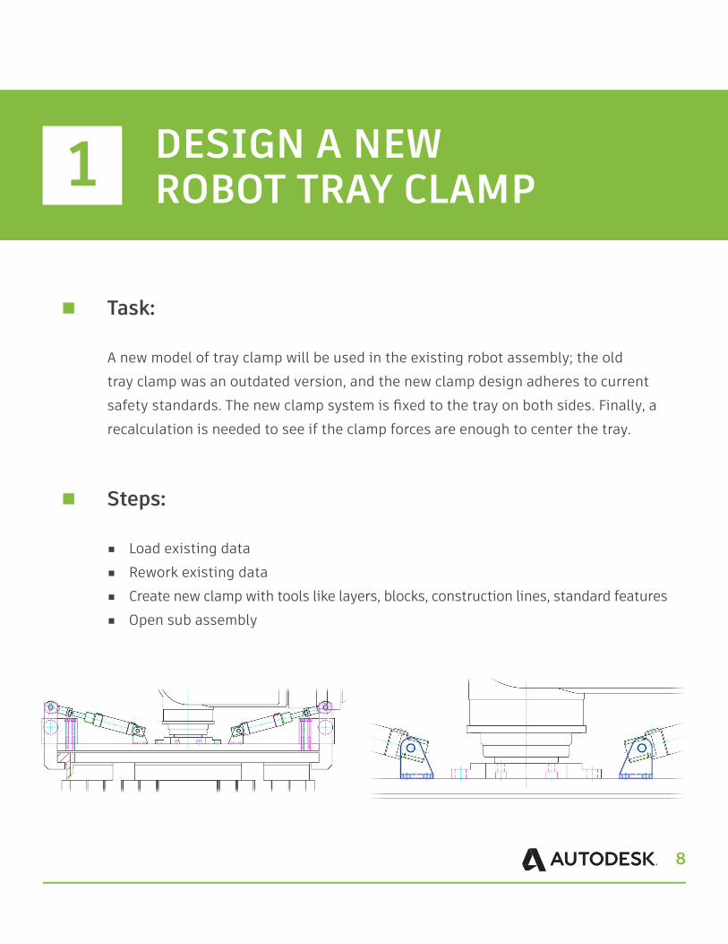
Task:
A new model of tray clamp will be used in the existing robot assembly; the old tray clamp was an outdated version, and the new clamp design adheres to current safety standards. The new clamp system is fixed to the tray on both sides. Finally, a recalculation is needed to see if the clamp forces are enough to center the tray.
Steps:
■ Load existing data ■ Rework existing data ■ Create new clamp with tools like layers, blocks, construction lines, standard features ■ Open sub assembly
DESIGN A NEW ROBOT TRAY CLAMP1
9
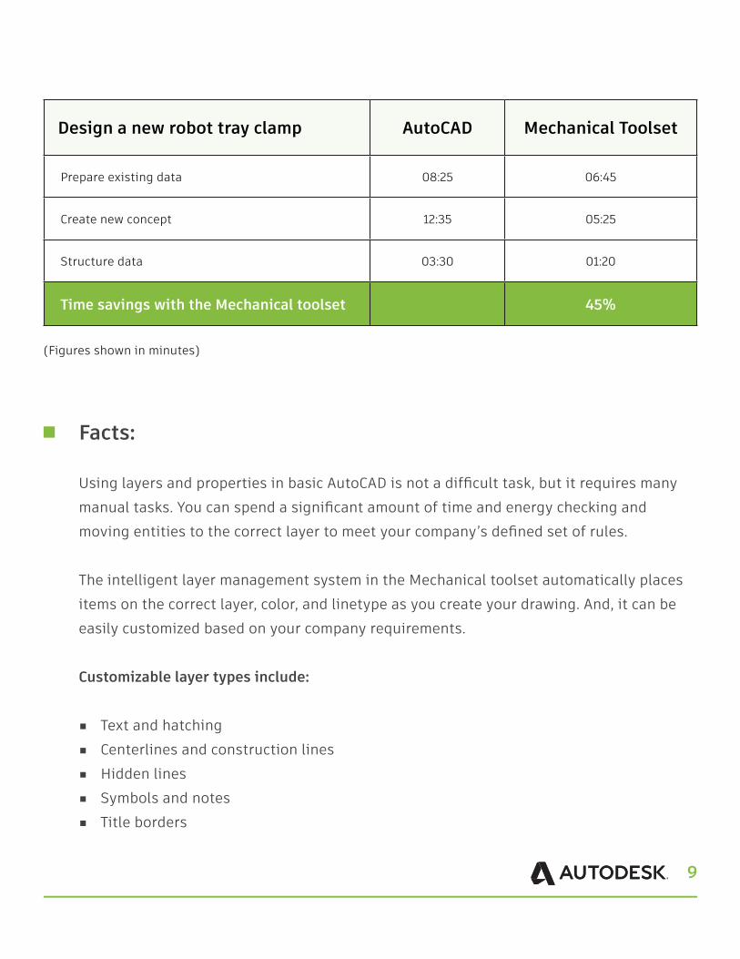
Design a new robot tray clamp AutoCAD Mechanical Toolset
Prepare existing data 08:25 06:45
Create new concept 12:35 05:25
Structure data 03:30 01:20
Time savings with the Mechanical toolset 45%
(Figures shown in minutes)
Facts:
Using layers and properties in basic AutoCAD is not a difficult task, but it requires many manual tasks. You can spend a significant amount of time and energy checking and moving entities to the correct layer to meet your company’s defined set of rules.
The intelligent layer management system in the Mechanical toolset automatically places items on the correct layer, color, and linetype as you create your drawing. And, it can be easily customized based on your company requirements.
Customizable layer types include:
■ Text and hatching ■ Centerlines and construction lines ■ Hidden lines ■ Symbols and notes ■ Title borders
10
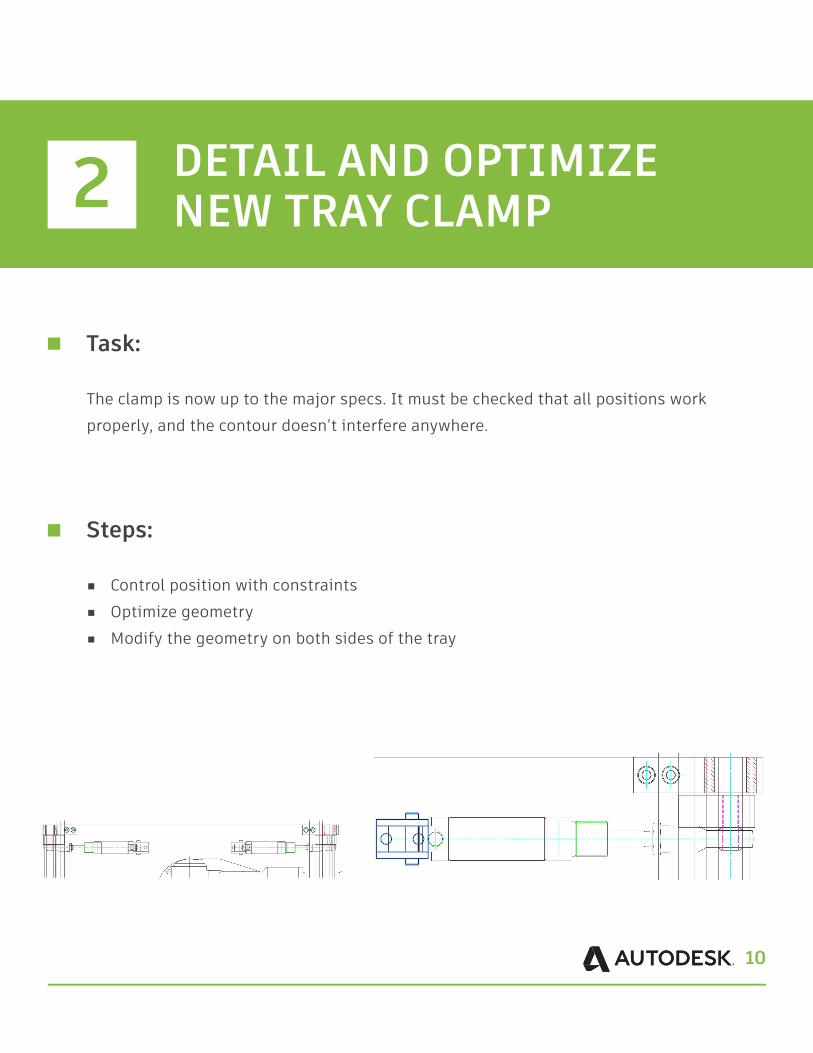
Task:
The clamp is now up to the major specs. It must be checked that all positions work properly, and the contour doesn’t interfere anywhere.
Steps:
■ Control position with constraints■ Optimize geometry ■ Modify the geometry on both sides of the tray
2 DETAIL AND OPTIMIZENEW TRAY CLAMP
11
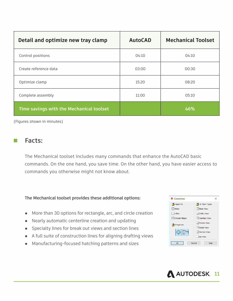
Detail and optimize new tray clamp AutoCAD Mechanical Toolset
Control positions 04:10 04:10
Create reference data 03:00 00:30
Optimize clamp 15:20 08:20
Complete assembly 11:00 05:10
Time savings with the Mechanical toolset 46%
(Figures shown in minutes)
Facts:
The Mechanical toolset includes many commands that enhance the AutoCAD basic commands. On the one hand, you save time. On the other hand, you have easier access to commands you otherwise might not know about.
The Mechanical toolset provides these additional options:
■ More than 30 options for rectangle, arc, and circle creation ■ Nearly automatic centerline creation and updating ■ Specialty lines for break out views and section lines ■ A full suite of construction lines for aligning drafting views ■ Manufacturing-focused hatching patterns and sizes
12
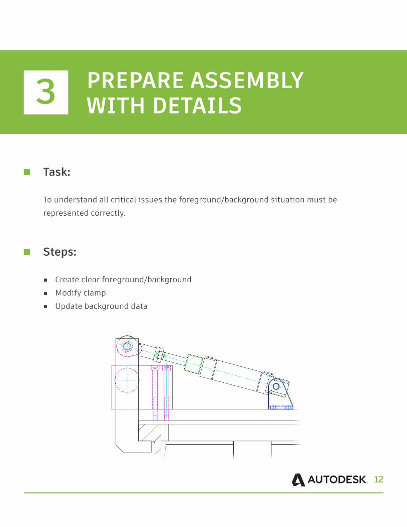
Task:
To understand all critical issues the foreground/background situation must be represented correctly.
Steps:
■ Create clear foreground/background ■ Modify clamp ■ Update background data
3 PREPARE ASSEMBLY WITH DETAILS

13
Prepare assembly with details AutoCAD Mechanical Toolset
Modify background contour 06:20 00:50
Modify holes in clamp 03:00 01:10
Update background contour 05:00 00:00
Time savings with the Mechanical toolset 86%
(Figures shown in minutes)
Facts:
The basic AutoCAD software requires a lot of manual work and geometry manipulation to accurately represent parts and features that are partially or completely hidden in drawing views. Even in the simplest situation where one plate partially obstructs the view of another plate, several lines must be broken, trimmed, and then hidden in the drawing view. This design process is labor-intensive and tedious, reducing the time available for mechanical design.
Ramp up productivity by defining simple foreground and background selections that automatically redraw geometry to show hidden or dashed lines of parts that are obstructed by other parts in a design. Hidden lines automatically update when changes occur, virtually eliminating the need to manually redraw geometry due to design changes. For the first time in 2D, identical parts can have different geometrical appearances when hidden, but the Mechanical toolset recognizes that they are still identical parts if you need to change the design or get an accurate count for the parts list. This means you spend less time and effort updating your 2D designs.
14
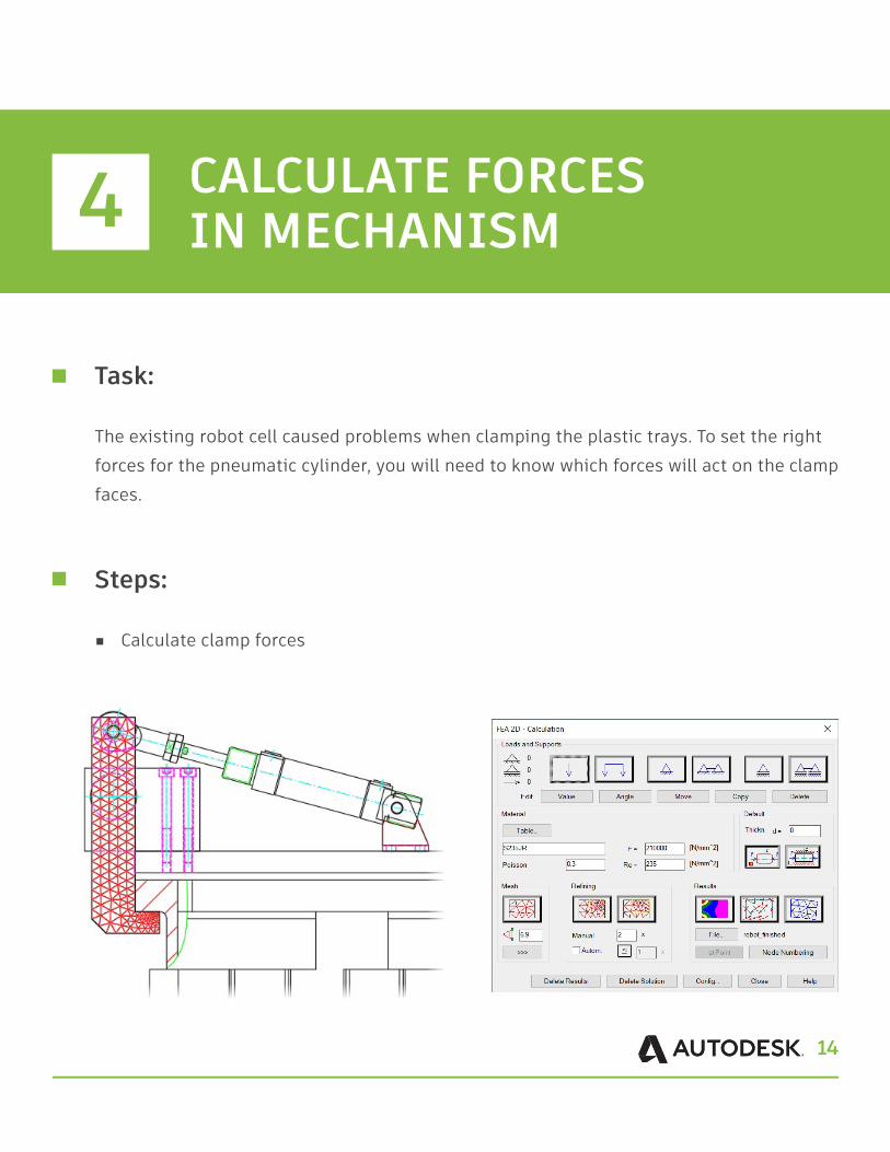
Task:
The existing robot cell caused problems when clamping the plastic trays. To set the right forces for the pneumatic cylinder, you will need to know which forces will act on the clamp faces.
Steps:
■ Calculate clamp forces
4 CALCULATE FORCES IN MECHANISM
15
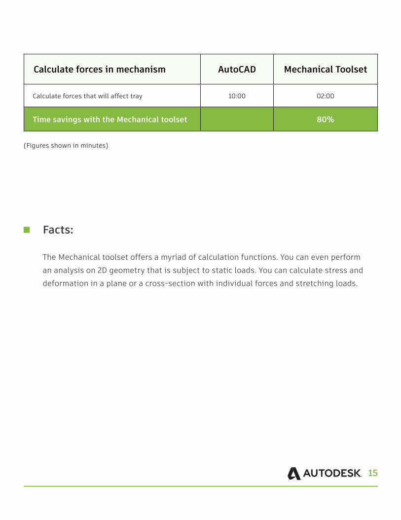
Calculate forces in mechanism AutoCAD Mechanical Toolset
Calculate forces that will affect tray 10:00 02:00
Time savings with the Mechanical toolset 80%
(Figures shown in minutes)
Facts:
The Mechanical toolset offers a myriad of calculation functions. You can even perform an analysis on 2D geometry that is subject to static loads. You can calculate stress and deformation in a plane or a cross-section with individual forces and stretching loads.
16
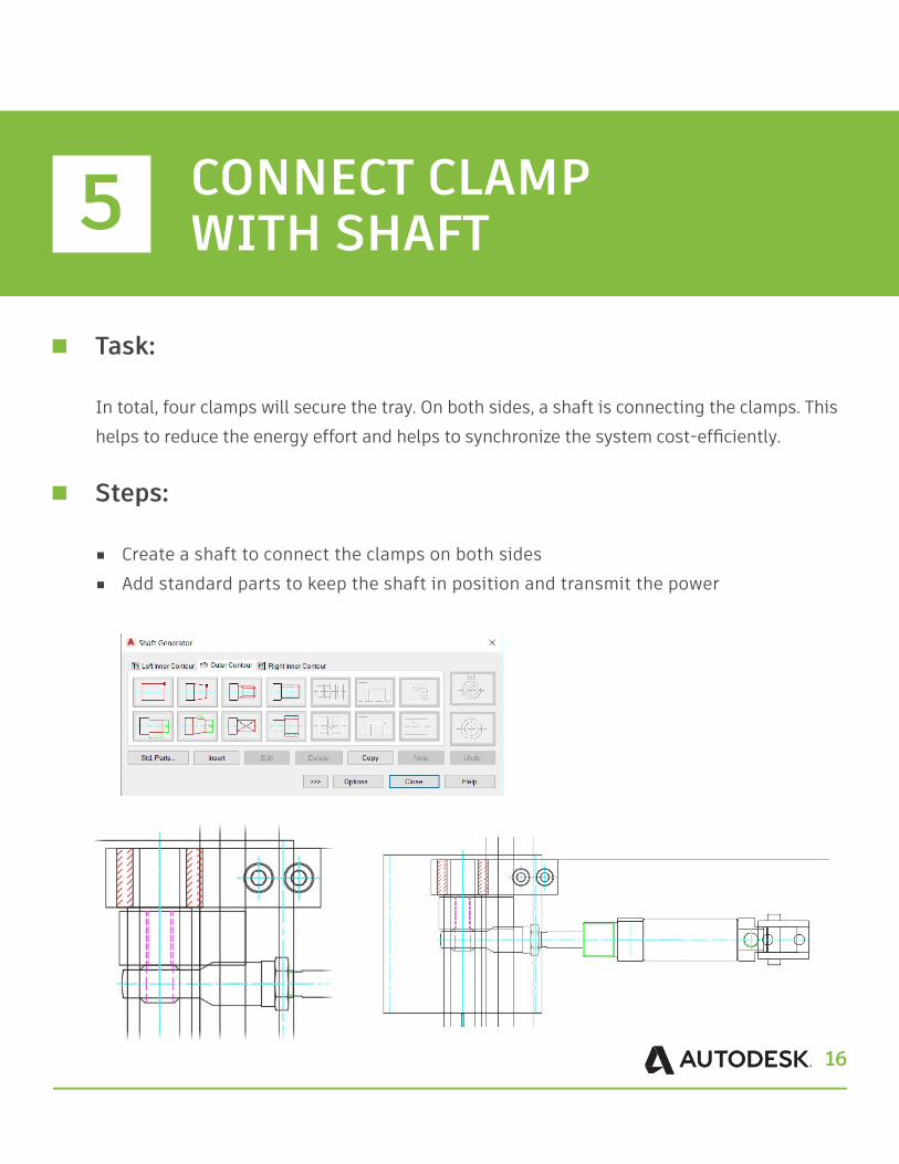
Task:
In total, four clamps will secure the tray. On both sides, a shaft is connecting the clamps. This helps to reduce the energy effort and helps to synchronize the system cost-efficiently.
Steps:
■ Create a shaft to connect the clamps on both sides ■ Add standard parts to keep the shaft in position and transmit the power
5 CONNECT CLAMP WITH SHAFT
17
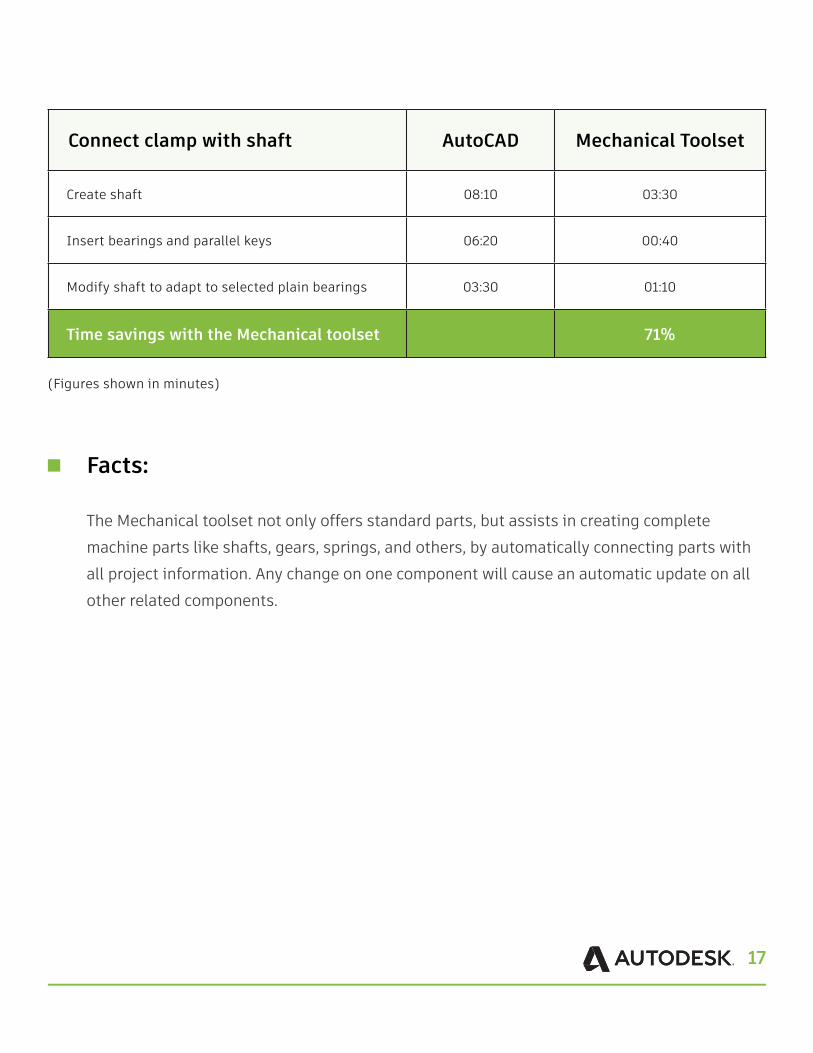
Connect clamp with shaft AutoCAD Mechanical Toolset
Create shaft 08:10 03:30
Insert bearings and parallel keys 06:20 00:40
Modify shaft to adapt to selected plain bearings 03:30 01:10
Time savings with the Mechanical toolset 71%
(Figures shown in minutes)
Facts:
The Mechanical toolset not only offers standard parts, but assists in creating complete machine parts like shafts, gears, springs, and others, by automatically connecting parts with all project information. Any change on one component will cause an automatic update on all other related components.
18
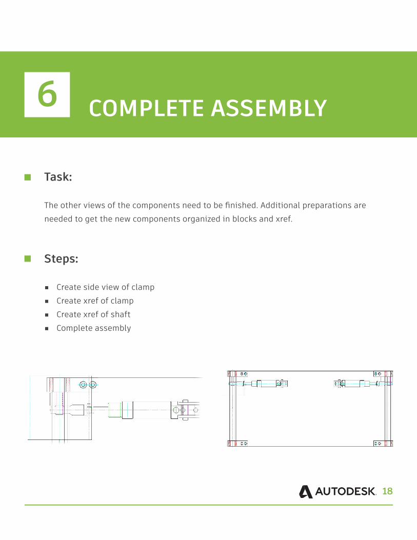
Task:
The other views of the components need to be finished. Additional preparations are needed to get the new components organized in blocks and xref.
Steps:
■ Create side view of clamp ■ Create xref of clamp ■ Create xref of shaft ■ Complete assembly
6 COMPLETE ASSEMBLY
19
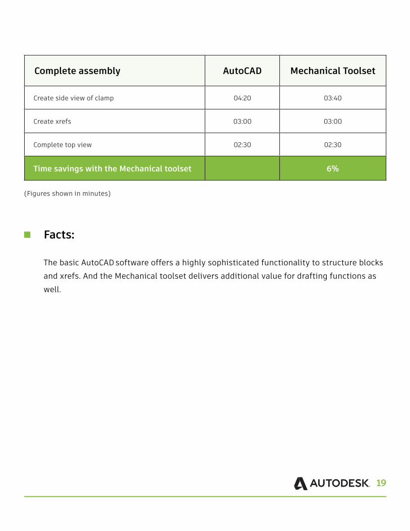
Complete assembly AutoCAD Mechanical Toolset
Create side view of clamp 04:20 03:40
Create xrefs 03:00 03:00
Complete top view 02:30 02:30
Time savings with the Mechanical toolset 6%
(Figures shown in minutes)
Facts:
The basic AutoCAD software offers a highly sophisticated functionality to structure blocks and xrefs. And the Mechanical toolset delivers additional value for drafting functions as well.
20
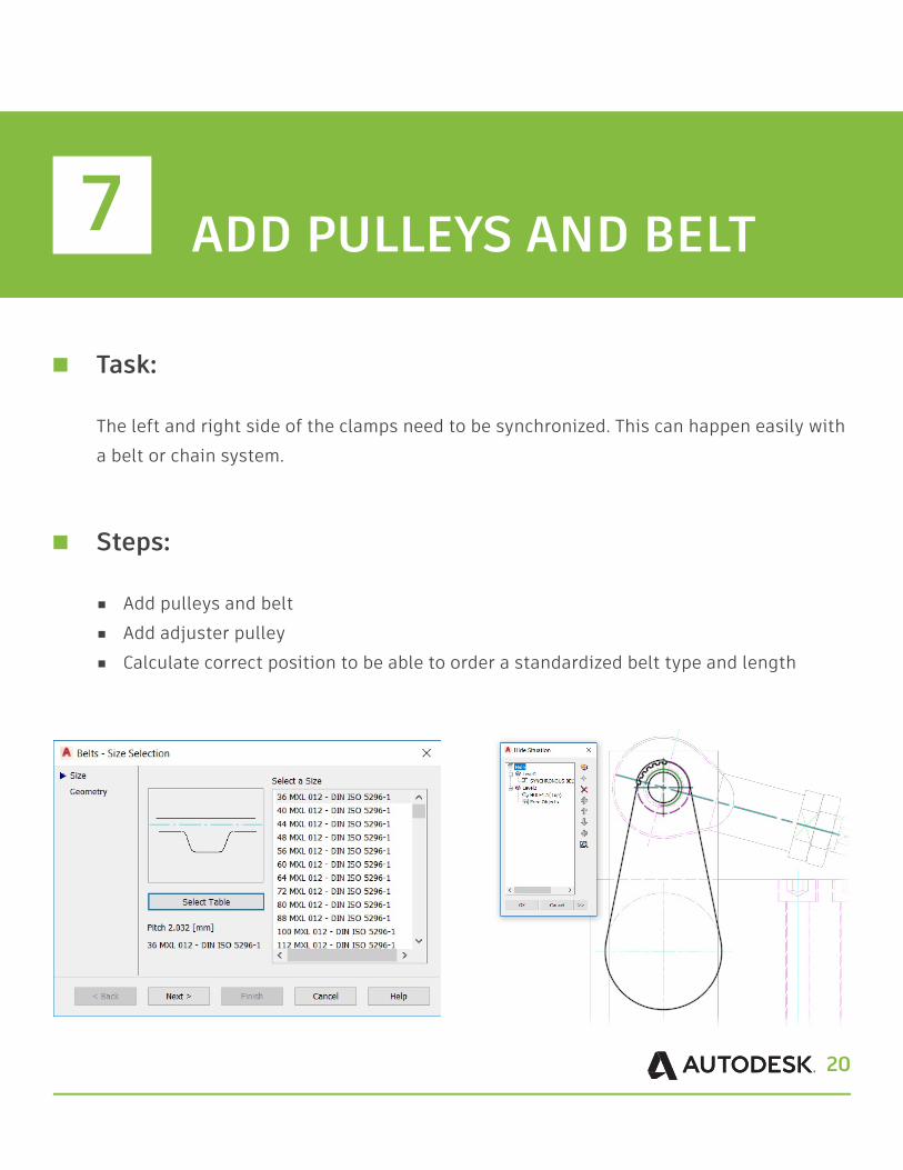
Task:
The left and right side of the clamps need to be synchronized. This can happen easily with a belt or chain system.
Steps:
■ Add pulleys and belt■ Add adjuster pulley ■ Calculate correct position to be able to order a standardized belt type and length
7 ADD PULLEYS AND BELT
21
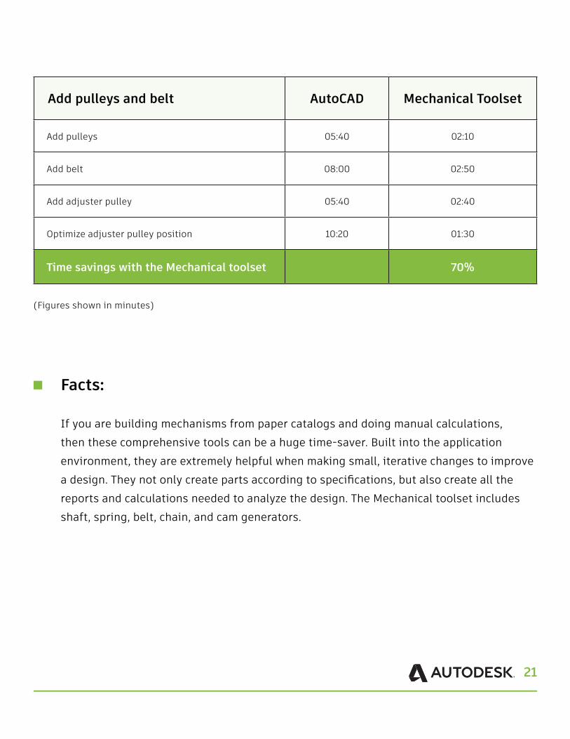
Add pulleys and belt AutoCAD Mechanical Toolset
Add pulleys 05:40 02:10
Add belt 08:00 02:50
Add adjuster pulley 05:40 02:40
Optimize adjuster pulley position 10:20 01:30
Time savings with the Mechanical toolset 70%
(Figures shown in minutes)
Facts:
If you are building mechanisms from paper catalogs and doing manual calculations, then these comprehensive tools can be a huge time-saver. Built into the application environment, they are extremely helpful when making small, iterative changes to improve a design. They not only create parts according to specifications, but also create all the reports and calculations needed to analyze the design. The Mechanical toolset includes shaft, spring, belt, chain, and cam generators.
22
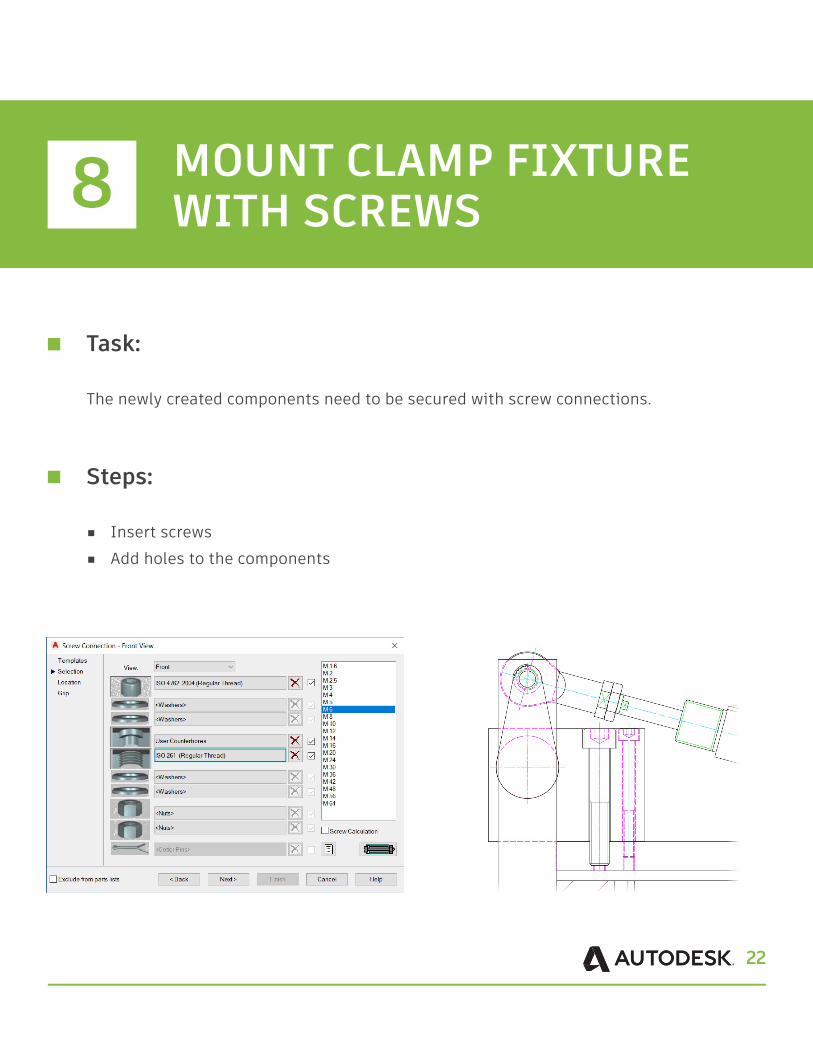
Task:
The newly created components need to be secured with screw connections.
Steps:
■ Insert screws ■ Add holes to the components
8 MOUNT CLAMP FIXTURE WITH SCREWS
23
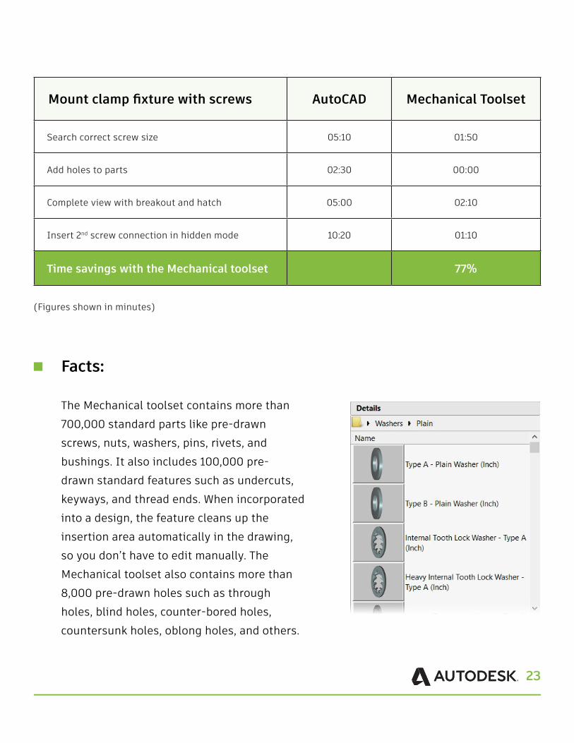
Mount clamp fixture with screws AutoCAD Mechanical Toolset
Search correct screw size 05:10 01:50
Add holes to parts 02:30 00:00
Complete view with breakout and hatch 05:00 02:10
Insert 2nd screw connection in hidden mode 10:20 01:10
Time savings with the Mechanical toolset 77%
(Figures shown in minutes)
Facts:
The Mechanical toolset contains more than 700,000 standard parts like pre-drawn screws, nuts, washers, pins, rivets, and bushings. It also includes 100,000 pre-drawn standard features such as undercuts, keyways, and thread ends. When incorporated into a design, the feature cleans up the insertion area automatically in the drawing, so you don’t have to edit manually. The Mechanical toolset also contains more than 8,000 pre-drawn holes such as through holes, blind holes, counter-bored holes, countersunk holes, oblong holes, and others.
24
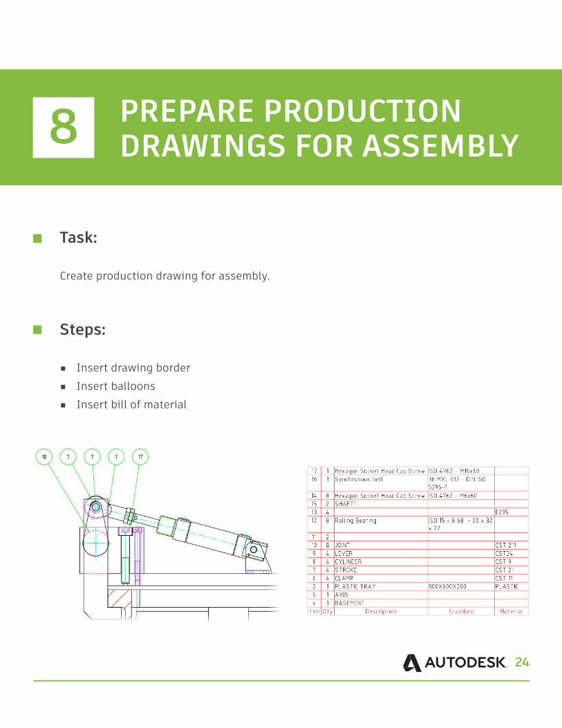
Task:
Create production drawing for assembly.
Steps:
■ Insert drawing border ■ Insert balloons ■ Insert bill of material
8 PREPARE PRODUCTION DRAWINGS FOR ASSEMBLY
25
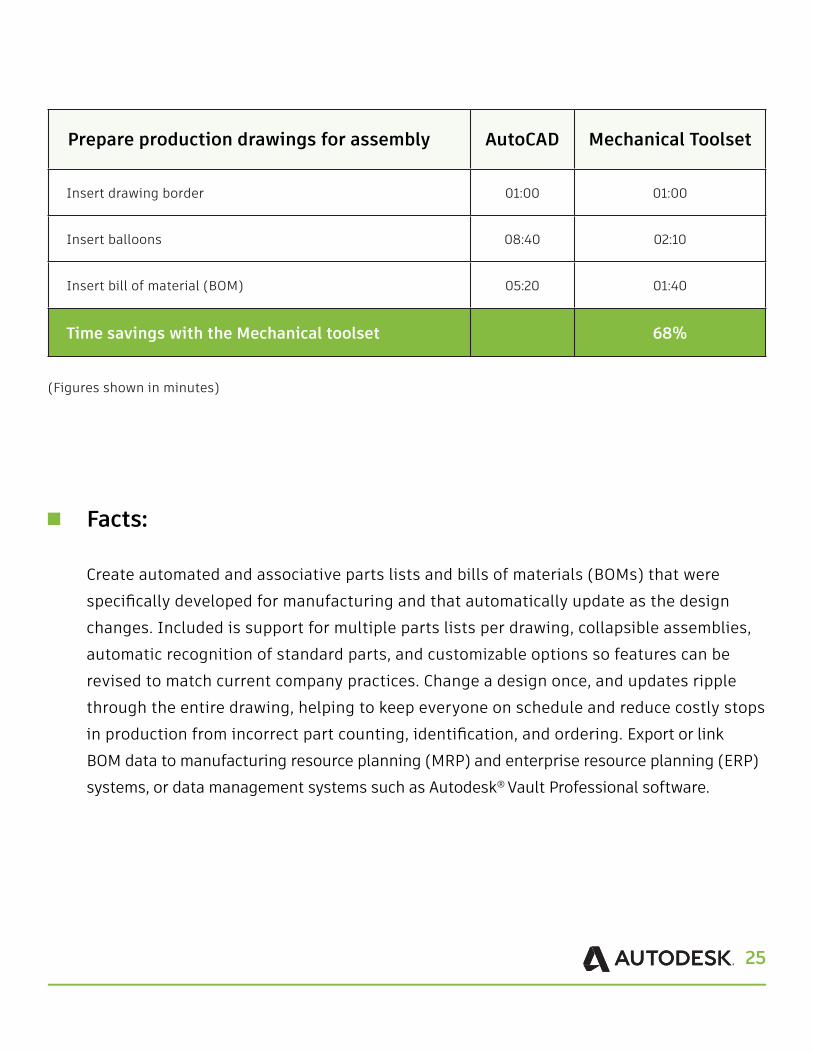
Prepare production drawings for assembly AutoCAD Mechanical Toolset
Insert drawing border 01:00 01:00
Insert balloons 08:40 02:10
Insert bill of material (BOM) 05:20 01:40
Time savings with the Mechanical toolset 68%
(Figures shown in minutes)
Facts:
Create automated and associative parts lists and bills of materials (BOMs) that were specifically developed for manufacturing and that automatically update as the design changes. Included is support for multiple parts lists per drawing, collapsible assemblies, automatic recognition of standard parts, and customizable options so features can be revised to match current company practices. Change a design once, and updates ripple through the entire drawing, helping to keep everyone on schedule and reduce costly stops in production from incorrect part counting, identification, and ordering. Export or link BOM data to manufacturing resource planning (MRP) and enterprise resource planning (ERP) systems, or data management systems such as Autodesk® Vault Professional software.
26
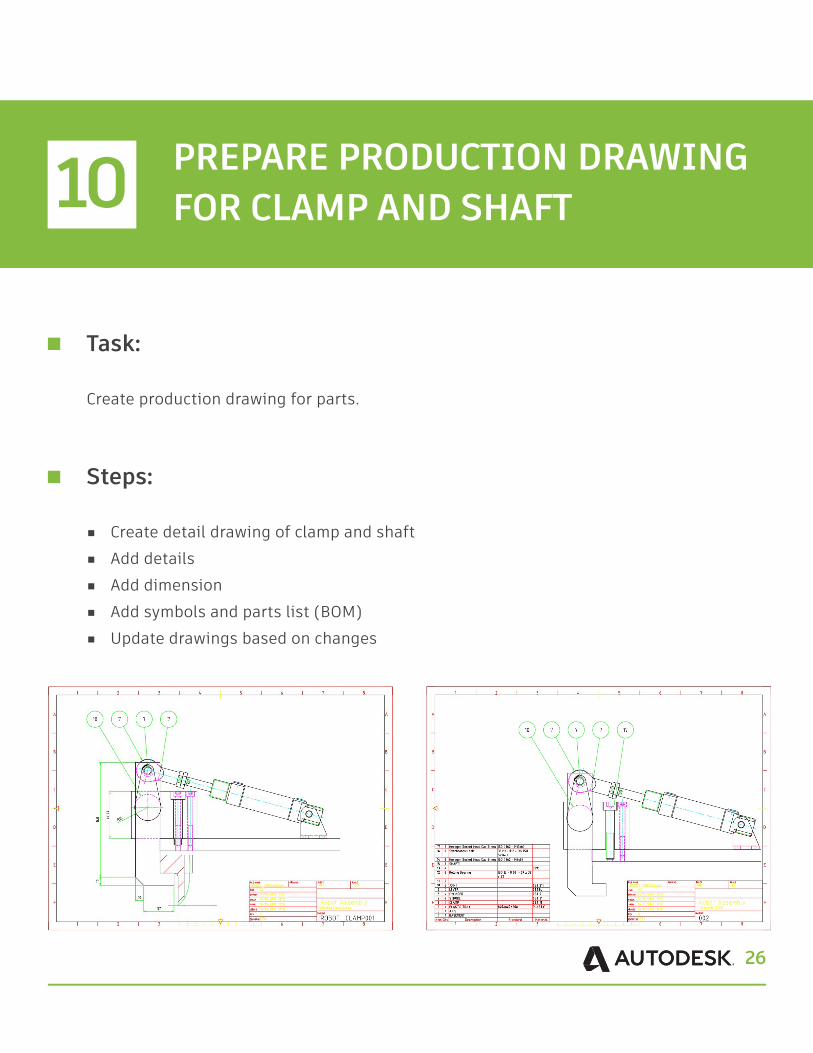
Task:
Create production drawing for parts.
Steps:
■ Create detail drawing of clamp and shaft ■ Add details ■ Add dimension ■ Add symbols and parts list (BOM)■ Update drawings based on changes
10 PREPARE PRODUCTION DRAWING FOR CLAMP AND SHAFT

27
Prepare production drawings for clamp and shaft AutoCAD Mechanical Toolset
Create missing views/details on parts 11:10 04:00
Add dimensions 07:10 04:30
Add annotations 05:00 03:20
Modify drawing scale 03:10 00:30
Add details and parts list (BOM) 02:00 01:10
Insert screw connection in hidden mode 10:10 01:10
Time savings with the Mechanical toolset 62%
(Figures shown in minutes)
Facts:
Powerful and smart dimensions
With the streamlined tools in the Mechanical toolset, you can create dimensions using abbreviated dialog boxes that conveniently control and expand only the relevant variables for manufacturing. With automatic dimensioning, you can create multiple dimensions with minimal input, resulting in instant groups of ordinate, parallel, or symmetric items that are appropriately spaced. Smart dimensioning tools force overlapping dimensions to automatically space themselves appropriately while integrating tolerance and fit list information into the design. Dimension input can even drive and change design geometry to fit certain sizes.
28
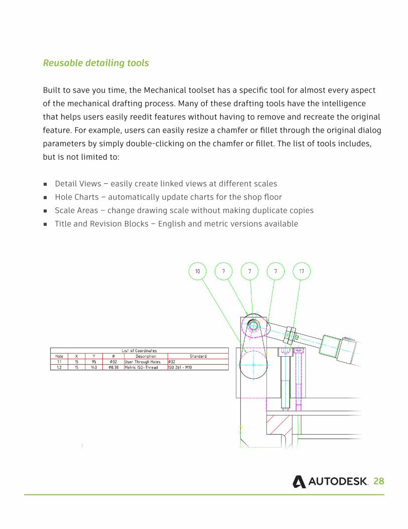
Reusable detailing tools
Built to save you time, the Mechanical toolset has a specific tool for almost every aspect of the mechanical drafting process. Many of these drafting tools have the intelligence that helps users easily reedit features without having to remove and recreate the original feature. For example, users can easily resize a chamfer or fillet through the original dialog parameters by simply double-clicking on the chamfer or fillet. The list of tools includes, but is not limited to:
■ Detail Views – easily create linked views at different scales ■ Hole Charts – automatically update charts for the shop floor ■ Scale Areas – change drawing scale without making duplicate copies ■ Title and Revision Blocks – English and metric versions available
29
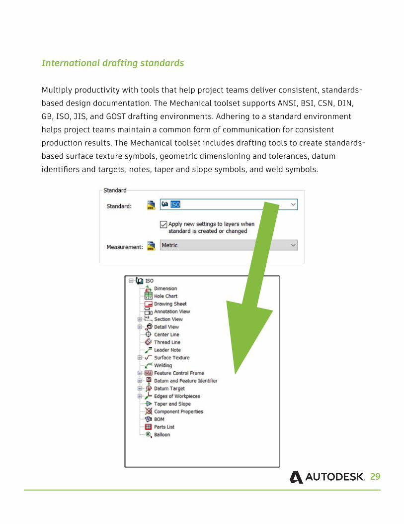
International drafting standards
Multiply productivity with tools that help project teams deliver consistent, standards-based design documentation. The Mechanical toolset supports ANSI, BSI, CSN, DIN, GB, ISO, JIS, and GOST drafting environments. Adhering to a standard environment helps project teams maintain a common form of communication for consistent production results. The Mechanical toolset includes drafting tools to create standards-based surface texture symbols, geometric dimensioning and tolerances, datum identifiers and targets, notes, taper and slope symbols, and weld symbols.
30
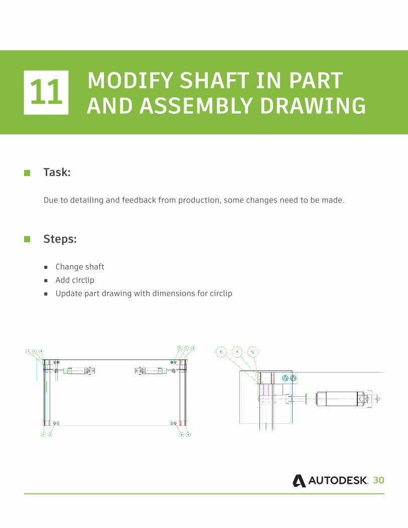
Task:
Due to detailing and feedback from production, some changes need to be made.
Steps:
■ Change shaft ■ Add circlip ■ Update part drawing with dimensions for circlip
11 MODIFY SHAFT IN PART AND ASSEMBLY DRAWING
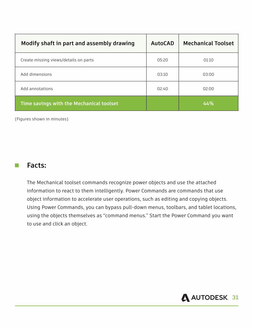
31
Modify shaft in part and assembly drawing AutoCAD Mechanical Toolset
Create missing views/details on parts 05:20 01:10
Add dimensions 03:10 03:00
Add annotations 02:40 02:00
Time savings with the Mechanical toolset 44%
(Figures shown in minutes)
Facts:
The Mechanical toolset commands recognize power objects and use the attached information to react to them intelligently. Power Commands are commands that use object information to accelerate user operations, such as editing and copying objects. Using Power Commands, you can bypass pull-down menus, toolbars, and tablet locations, using the objects themselves as “command menus.” Start the Power Command you want to use and click an object.
32
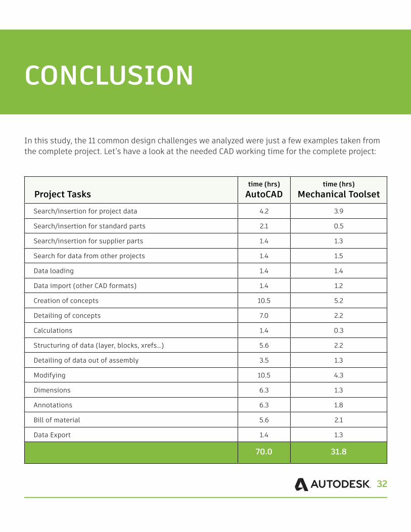
In this study, the 11 common design challenges we analyzed were just a few examples taken from the complete project. Let’s have a look at the needed CAD working time for the complete project:
CONCLUSION
Project Tasks
time (hrs)AutoCAD
time (hrs)Mechanical Toolset
Search/insertion for project data 4.2 3.9
Search/insertion for standard parts 2.1 0.5
Search/insertion for supplier parts 1.4 1.3
Search for data from other projects 1.4 1.5
Data loading 1.4 1.4
Data import (other CAD formats) 1.4 1.2
Creation of concepts 10.5 5.2
Detailing of concepts 7.0 2.2
Calculations 1.4 0.3
Structuring of data (layer, blocks, xrefs…) 5.6 2.2
Detailing of data out of assembly 3.5 1.3
Modifying 10.5 4.3
Dimensions 6.3 1.3
Annotations 6.3 1.8
Bill of material 5.6 2.1
Data Export 1.4 1.3
70.0 31.8
33
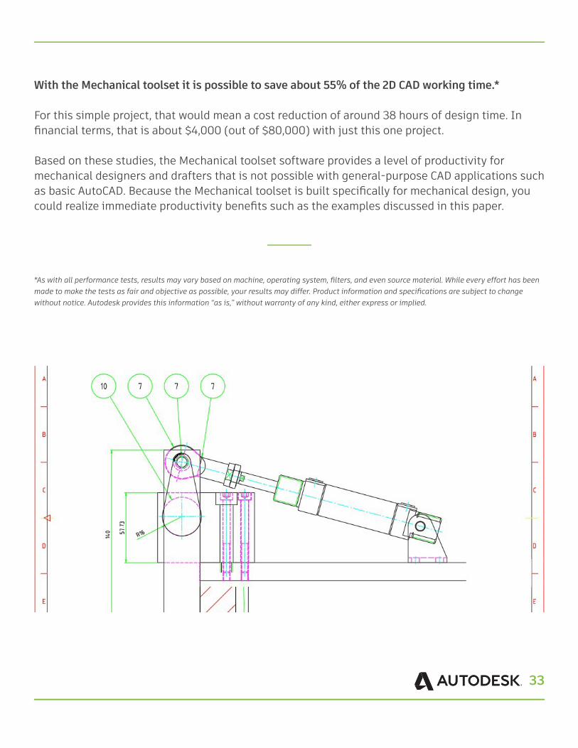
With the Mechanical toolset it is possible to save about 55% of the 2D CAD working time.*
For this simple project, that would mean a cost reduction of around 38 hours of design time. In financial terms, that is about $4,000 (out of $80,000) with just this one project.
Based on these studies, the Mechanical toolset software provides a level of productivity for mechanical designers and drafters that is not possible with general-purpose CAD applications such as basic AutoCAD. Because the Mechanical toolset is built specifically for mechanical design, you could realize immediate productivity benefits such as the examples discussed in this paper.
*As with all performance tests, results may vary based on machine, operating system, filters, and even source material. While every effort has been made to make the tests as fair and objective as possible, your results may differ. Product information and specifications are subject to change without notice. Autodesk provides this information “as is,” without warranty of any kind, either express or implied.

Autodesk, the Autodesk logo, AutoCAD® are registered trademarks or trademarks of Autodesk, Inc., and/or its subsidiaries and/or affiliates in the USA and/or other countries. All other brand names, product names, or trademarks belong to their respective holders. Autodesk reserves the right to alter product and services offerings, and specifications and pricing at any time without notice, and is not responsible for typographical or graphical errors that may appear in this document. © 2018
Autodesk, Inc. All rights reserved.