the belts or ropes are used to transmit power from one shaft to another by means of pulleys which...
TRANSCRIPT

BELTS, ROPES & CHAIN DRIVES
The belts or ropes are used to transmit power from one shaft to another by means of pulleys which rotate at the same speed or at different speeds. The amount of power transmitted depends upon the following factors :
1. The velocity of the belt.2. The tension under which the belt is placed on the
pulleys.3. The arc of contact between the belt and the
smaller pulley.4. The conditions under which the belt is used.

SELECTION OF A BELT DRIVEFollowing are the various important factors upon which the selection of a belt drive depends:
1. Speed of the driving and driven shafts, 2. Speed reduction ratio,3. Power to be transmitted, 4. Centre distance between the shafts,5. Positive drive requirements, 6. Shafts layout,7. Space available, and 8. Service conditions.

TYPES OF BELT DRIVES
The belt drives are usually classified into the following three groups :
1. Light drives. These are used to transmit small powers at belt speeds upto about 10 m/s, as in agricultural machines and small machine tools.
2. Medium drives. These are used to transmit medium power at belt speeds over 10 m/s but up to 22 m/s, as in machine tools.
3. Heavy drives. These are used to transmit large powers at belt speeds above 22 m/s, as in compressors and generators.

TYPES OF BELTS
Though there are many types of belts used these days, yet the following are important from the subject point of view :
1. Flat belt.:- The flat belt, as shown in Fig.(a), is mostly used in the factories and workshops, where a moderate amount of power is to be transmitted, from one pulley to another when the two pulleys are not more than 8 metres apart.
2. V-belt. The V-belt, as shown in Fig.(b), is mostly used in the factories and workshops, where a moderate amount of power is to be transmitted, from one pulley to another, when the two pulleys are very near to each other.
3. Circular belt or rope. The circular belt or rope, as shown in Fig(c), is mostly used in the factories and workshops, where a great amount of power is to be transmitted, from one pulley to another, when the two pulleys are more than 8 meters apart.


MATERIAL USED FOR BELTS
The material used for belts and ropes must be strong, flexible, and durable. It must have a high coefficient of friction. The belts, according to the material used, are classified as follows :
1. Leather belts. The most important material for the belt is leather. The best leather belts are made from 1.2 metres to 1.5 metres long strips cut from either side of the back bone of the top grade steer hides. The hair side of the leather is smoother and harder than the flesh side, but the flesh side is Stronger. The leather may be either oak-tanned or mineral salt tanned e.g. chrome tanned. In order to increase the thickness of belt, the strips are cemented together. The belts are specified according to the number of layers e.g. single, double or triple ply and according to the thickness of hides used e.g. light, medium or heavy. The leather belts must be periodically cleaned and dressed or treated with a compound or dressing containing neats foot or other suitable oils so that the belt will remain soft and flexible.
2. Cotton or fabric belts. Most of the fabric belts are made by folding canvass or cotton duck to three or more layers (depending upon the thickness desired) and stitching together. These belts are woven also into a strip of the desired width and thickness. They are impregnated with some filler like linseed oil in order to make the belts water proof and to prevent injury to the fibres. The cotton belts are cheaper and suitable in warm climates, in damp atmospheres and in exposed positions. Since the cotton belts require little attention, therefore these belts are mostly used in farm machinery, belt conveyor etc.
3. Rubber belt. The rubber belts are made of layers of fabric impregnated with rubber composition and have a thin layer of rubber on the faces. These belts are very flexible but are quickly destroyed if allowed to come into contact with heat, oil or grease. One of the principal advantage of these belts is that they may be easily made endless. These belts are found suitable for saw mills, paper mills where they are exposed to moisture.

TYPES OF FLAT BELT DRIVES
1. Open belt drive. The open belt drive, as shown in Fig. is used with shafts arrangedparallel and rotating in the same direction. In this case, the driver A pulls the belt from one side (i.e.lower side RQ) and delivers it to the other side (i.e. upper side LM). Thus the tension in the lower side belt will be more than that in the upper side belt. The lower side belt (because of more tension) isknown as tight side whereas the upper side belt (because of less tension) is known as slack side, asshown in Fig.

2. Crossed or twist belt drive. The crossed or twist belt drive, as shown in Fig. is used
with shafts arranged parallel and rotating in the opposite directions. In this case, the driver pulls the belt from one side (i.e. RQ) and delivers it to the
other side (i.e. LM). Thus the tension in the belt RQ will be more than that in the belt LM. The
belt RQ (because of more tension) is known as tight side, whereas the belt LM (because of less
tension) is known as slack side, as shown in Fig. A little consideration will show that at a point where the belt crosses, it rubs
against each other and there will be excessive wear and tear. In order to avoid this, the shafts
should be placed at a maximum distance of 20 b, where b is the width of belt and the speed of the belt
should be less than 15 m/s.

3. Quarter turn belt drive. The quarter turn belt drive also known as right angle belt drive, as shown in Fig. (a), is used with shafts arranged at right angles and rotating in one definite direction.In order to prevent the belt from leaving the pulley, the width of the face of the pulley should be greater or equal to 1.4 b, where b is the width of belt.In case the pulleys cannot be arranged, as shown in Fig. (a), or when the reversiblemotion is desired, then a quarter turn belt drive with guide pulley, as shown in Fig. (b), may be used.

4. Compound belt drive. A compound belt drive, as shown in Fig. is used when power is transmitted from one shaft to another through a number of pulleys.

VELOCITY RATIO OF BELT DRIVE
It is the ratio between the velocities of the driver and the follower or driven. It may be expressed, mathematically, as discussed below :
Let d1 = Diameter of the driver, d2 = Diameter of the follower,
N1 = Speed of the driver in r.p.m., and N2 = Speed of the follower in r.p.m. ∴ Length of the belt that passes over the driver, in one minute = π d1.N1 Similarly, length of the belt that passes over the follower, in one minute = π d2 . N2 Since the length of belt that passes over the driver in one minute is equal to the length of belt that passes over the follower in one minute, therefore π d1 . N1 = π d2 . N2
When the thickness of the belt (t) is considered, then velocity ratio,

SLIP OF BELT
In the previous articles, we have discussed the motion of belts and shafts assuming a firm frictional grip between the belts and the shafts. But sometimes, the frictional grip becomes insufficient. This may cause some forward motion of the driver without carrying the belt with it. This may also cause some forward motion of the belt without carrying the driven pulley with it. This is called slip of the belt and is generally
expressed as a percentage. The result of the belt slipping is to reduce the velocity ratio of the system. As the slipping of the belt is a common phenomenon, thus the belt should never be used where a definite velocity ratio is of importance (as in the case of hour, minute and second arms in a watch).

Let % = Slip between the driver and the belt,

CREEP OF BELT When the belt passes from the slack side to the tight side, a certain
portion of the belt extends and it contracts again when the belt passes from the tight side to
slack side. Due to these changes of length, there is a relative motion between the belt and the pulley
surfaces. This relative motion is termed as creep. The total effect of creep is to reduce slightly
the speed of the driven pulley or follower. Considering creep, the velocity ratio is
given by
Where σ1 and σ2 = Stress in the belt on the tight and slack side respectively, and E = Young’s modulus for the material of the belt.

LENGTH OF AN OPEN BELT DRIVE
We have already discussed that in an open belt drive, both the pulleys rotate in the same direction as shown in Fig.
Let r1 and r2 = Radii of the larger and smaller pulleys,
x = Distance between the centres of two pulleys (i.e. O1 O2), and
L = Total length of the belt.

Let the belt leaves the larger pulley at E and G and the smaller pulley at F and H as shown in Fig. Through O2, draw O2 M parallel to FE.From the geometry of the figure, we find that O2 M will be perpendicular to O1 E.Let the angle MO2 O1 = α radians. We know that the length of the belt, L = Arc GJE + EF + Arc FKH + HG = 2 (Arc JE + EF + Arc FK) ...(i) From the geometry of the figure, we find that


POWER TRANSMITTED BY A BELT
Fig. shows the driving pulley (or driver) A and the driven pulley (or follower) B. We
have already discussed that the driving pulley pulls the belt from one side and delivers the same to theother side. It is thus obvious that the tension on the former side (i.e. tight side) will be greater than the latter side (i.e. slack side) as shown in Fig.
Let T1 and T2 = Tensions in the tight and slack side of the belt respectively in newtons, r1 and r2 = Radii of the driver and follower respectively, and v = Velocity of the belt in m/s. The effective turning (driving) force at the circumference of the follower is the
difference between the two tensions (i.e. T1 – T2). ∴ Work done per second = (T1 – T2) v N-m/s and power transmitted, P = (T1 – T2) v W ...(∵ 1 N-m/s = 1 W) A little consideration will show that the torque exerted on the driving pulley is
(T1 – T2) r1. Similarly, the torque exerted on the driven pulley i.e. follower is (T1 – T2) r2.

DETERMINATION OF ANGLE OF CONTACT
When the two pulleys of different diameters are connected by means of an open belt as
shown in Fig. (a), then the angle of contact or lap (θ) at the smaller pulley must be taken into consideration.
Let r1 = Radius of larger pulley, r2 = Radius of smaller pulley, and x = Distance between centers of two pulleys (i.e. O1 O2).
∴ Angle of contact or lap,
A little consideration will show that when the two pulleys are connected by means of a crossed belt then the angle of contact or lap (θ) on both the pulleys is same.


CENTRIFUGAL TENSION
Since the belt continuously runs over the pulleys, therefore, some centrifugal force is caused, whose effect is to increase the tension on both, tight as well as the slack sides. The tension caused by centrifugal force is called centrifugal tension. At lower
belt speeds (less than 10 m/s), the centrifugal tension is very small, but at higher belt speeds (more than 10 m/s), its effect is considerable and thus should be taken into account. Consider a small portion PQ of the belt subtending an angle dӨ the centre of the pulley as shown in Fig.
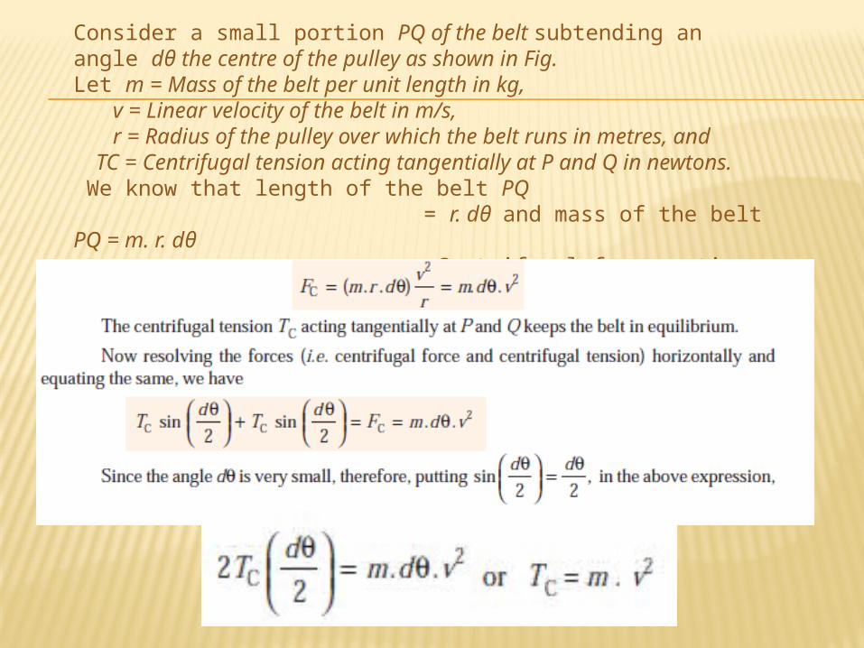
Consider a small portion PQ of the belt subtending an angle dθ the centre of the pulley as shown in Fig. Let m = Mass of the belt per unit length in kg, v = Linear velocity of the belt in m/s, r = Radius of the pulley over which the belt runs in metres, and TC = Centrifugal tension acting tangentially at P and Q in newtons. We know that length of the belt PQ = r. dθ and mass of the belt PQ = m. r. dθ ∴ Centrifugal force acting on the belt PQ,

MAXIMUM TENSION IN THE BELT
A little consideration will show that the maximum tension in the belt (T) is equal to the total
tension in the tight side of the belt (Tt1). Let σ = Maximum safe stress in N/mm2, b = Width of the belt in mm, and t = Thickness of the belt in mm. We know that maximum tension in the belt, T = Maximum stress × cross-sectional area of belt = σ. b. t When centrifugal tension is neglected, then T (or Tt1) = T1, i.e. Tension in the tight side of the belt and when centrifugal tension is considered, then T (or Tt1) = T1 + TC

V-BELT DRIVE
We have already discussed that a V-belt is mostly used in factories and workshops where a great amount of power is to be transmitted from one pulley to another when the two
pulleys are very near to each other. The V-belts are made of fabric and cords moulded in rubber and
covered with fabric andrubber, as shown in Fig.(a). These belts are moulded to a trapezoidal shape and are made
endless. These are particularly suitable for short drives i.e. when the shafts are at a short distance
apart. The included angle for the V-belt is usually from 30° – 40°. In case of flat belt drive, the belt
runs over the pulleys whereas in case of V-belt drive, the rim of the pulley is grooved in which the
V-belt runs. The effect of the groove is to increase the frictional grip of the V-belt on the pulley and
thus to reduce the tendency of slipping. In order to have a good grip on the pulley, the V-belt is in
contact with the side faces of the groove and not at the bottom. The power is transmitted by the
wedging action between the belt and the V-groove in the pulley.

A clearance must be provided at the bottom of the groove, as shown in Fig. (b), in order to prevent touching to the bottom as it becomes narrower from wear. The V-belt drive, may be inclined at any angle with tight side either at top or bottom. In order to increase the power output, several V- belts may be operated side by side. It may be noted that in multiple V-belt drive, all the belts should stretch at the same rate so that the load is equally divided between them. When one of the set of belts break, the entire set should be replaced at the same time. If only one belt is replaced, the new unworn and unstressed belt will be more tightly stretched and will move with different velocity.Advantages and Disadvantages of V-belt Drive
Over Flat Belt DriveAdvantages
1. The V-belt drive gives compactness due to the small distance between the centres of pulleys.2. The drive is positive, because the slip between the belt and the pulley groove is negligible.3. Since the V-belts are made endless and there is no joint trouble, therefore the drive is smooth.4. It provides longer life, 3 to 5 years.

Disadvantages
1. The V-belt drive cannot be used with large centre distances.2. The V-belts are not so durable as flat belts.3. The construction of pulleys for V-belts is more complicated than pulleys for flat belts.4. Since the V-belts are subjected to certain amount of creep, therefore these are not suitablefor constant speed application such as synchronous machines, and timing devices.5. The belt life is greatly influenced with temperature changes, improper belt tension andmismatching of belt lengths.6. The centrifugal tension prevents the use of V-belts at speeds below 5 m/s and above 50m/s.

ROPE DRIVE
The rope drives are widely used where a large amount of power is to be transmitted, from one pulley to another, over a considerable distance. It may be noted that the use of flat belts is limited for the transmission of moderate power from one pulley to another when the two pulleys are not morethan 8 metres apart. If large amounts of power are to be transmitted by the flat belt, then it would result in excessive belt cross-section. It may be noted that frictional grip in case of rope drives is more
than that in V-drive. One of the main advantage of rope drives is that a number of separate drives may
be taken from the one driving pulley. For example, in many spinning mills, the line shaft on each floor
is driven by ropes passing directly from the main engine pulley on the ground floor.
The rope drives use the following two types of ropes : 1. Fibre ropes, and 2. Wire ropes. The fibre ropes operate successfully when the pulleys are about 60
metres apart, while the wire ropes are used when the pulleys are upto 150 metres apart.

CHAIN DRIVES We have seen in belt and rope drives that slipping may occur. In order
to avoid slipping, steel chains are used. The chains are made up of rigid links which are hinged together in order to provide the necessary flexibility for warping around the driving and driven wheels. The wheels have projecting teeth and fit into the corresponding recesses, in the links of the chain as shown in Fig. The wheels and the chain are thus constrained to move together without slipping and ensures perfect velocity ratio. The toothed wheels are known as sprocket wheels or simply sprockets. These wheels resemble to spur gears. The chains are mostly used to transmit motion and power from one shaft to another, when the distance between the centres of the shafts is short such as in bicycles, motor cycles, agricultural machinery, road rollers, etc.

ADVANTAGES AND DISADVANTAGES OF CHAIN DRIVE OVER BELT OR ROPE DRIVE
Advantages
1. As no slip takes place during chain drive, hence perfect velocity ratio is obtained.
2. Since the chains are made of metal, therefore they occupy less space in width than a belt or rope drive.
3. The chain drives may be used when the distance between the shafts is less.
4. The chain drive gives a high transmission efficiency (upto 98 per cent). 5. The chain drive gives less load on the shafts. 6. The chain drive has the ability of transmitting motion to several shafts by
one chain only.
Disadvantages
1. The production cost of chains is relatively high. 2. The chain drive needs accurate mounting and careful maintenance. 3. The chain drive has velocity fluctuations especially when unduly stretched.
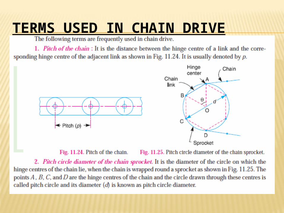
TERMS USED IN CHAIN DRIVE

RELATION BETWEEN PITCH AND PITCH CIRCLE DIAMETER