the basics of matchmovingcatalogimages.wiley.com/images/db/pdf/0782144039.excerpt.pdf1 the basics of...
TRANSCRIPT
1
■ T
HE
BA
SIC
S O
F M
AT
CH
MO
VIN
G
Chapter Contents
A Typical Matchmove
From 3D to 2D and Back Again
The Matchmove Process
Matchmoving in the Production Pipeline
Perspective Matching Tutorial
The Basics ofMatchmoving
Anytime a computer-generated (CG) element
needs to be placed into a live-action sequence or
vice versa, a matchmove is required. But what
exactly is matchmoving?
Matchmoving is the process of matching CG ele-
ments into live-action footage. As a result, it’s a
crucial part of many visual effects shots. Despite
its importance, it is completely invisible in the
final shot—that is, if it’s done right.
In this chapter, I explain the key steps involved in
a matchmove and how matchmovers work with
the rest of the visual effects team. I’ve also included
a tutorial that is designed to help you get comfort-
able working with cameras and perspective.1
4403c01.qxd 1/27/05 12:44 PM Page 1
COPYRIG
HTED M
ATERIAL
2
CH
AP
TE
R1
:T
HE
BA
SIC
S O
F
MA
TC
HM
OV
ING
■
A Typical Matchmove
In order to better understand what matchmovers do, let’s consider a typical visualeffects shot. The director has called for a CG creature to crash out of window of abuilding and run across the street and into an alley. Because the monster will need tointeract with the window, the visual effects supervisor decides that in addition to themonster, the window-shattering effect should also be done in the computer.
On the day of shooting, the director makes artistic decisions as to how he wantsto shoot the scene and eventually decides on a camera position that he likes. There isan opening on the building where the window should be, although the panes of glassare missing. The director and the cameraman practice the camera move a few timesand watch the video playback to see how it looks. When they are filming, they movethe camera as though it were following the monster crashing through the window andrunning across the street, even though the monster isn’t there. Extras react to the imag-inary beast, and props around the window are rigged with monofilament string (fishingline) to be pulled down on cue as though they were knocked over. Once the director ishappy with the shot, the film is sent off to be digitized and then given to the visualeffects artists to add the monster.
When the visual effects studio receives the digitized sequence (known as a plate),they decide that they will need an animator to animate the creature and a technicaldirector (TD) to do the glass-shattering effect. And, of course, they’ll need a match-mover to matchmove the plate.
The visual effects artists’ goals are to make their 3D elements look as realistic asthe scene that was filmed. The animator will need to make the creature move as thoughit were really crashing through a window, and the TD will need to make the windowshatter like a real window. The matchmover needs to figure out where the camera wasand how it was moving when the scene was filmed.
Matchmovers play an important role in this case, because in order for the crea-ture and window to appear matched realistically with the scene, they need to make surethat the CG objects are “filmed” the same way with their CG camera as the real setwas filmed with the real camera. Consider the window that needs to shatter—if theperspective of the window doesn’t match the perspective in the plate, it will look out of place. Furthermore, if the real camera moves to the left and the CG window staysput, everyone will know it’s a fake.
In our example effects shot, the visual effects supervisor measures key items on the set. For example, she measures the size of the opening of the window as wellas its height off the ground. She measures the distance across the street and the sizeof the opening to the alleyway. She draws a rough picture of the set and makes notesabout positions of certain props and lights that might be useful to know. She also
4403c01.qxd 1/27/05 12:44 PM Page 2
3
■ A
TY
PIC
AL
MA
TC
HM
OV
E
measures how high the camera is off the ground, what lens is used, and how far it isfrom the window.
Typically the animator, TD, and matchmover all start at the same time. Sincethere are some measurements of the set, the animator knows how high the creatureneeds to jump to get through the window and how far to make it run across the street.The TD knows the size of the window that needs to shatter and how high it is off theground. This is enough information to allow them to start setting up their scenes.
While they’re doing that, the matchmover starts by first examining the footageto get an idea of how the camera was moving during the shot. He brings the footageinto his matchmoving software and begins to track the 2D features in the scene as theymove around the screen. 2D tracking usually involves identifying things in the scene thatdon’t move (such as the corner of a building) and then letting the software follow thatfeature as the footage plays.
Once the matchmover has tracked a number of 2D tracks, the software analyzesthese tracks and computes the position of the camera in relation to the items in thescene. At the end of this process, the matchmover exports a scene to his 3D-animationpackage that includes an animated camera and the 3D positions for all of the featureshe tracked.
Once the matchmover is happy with the camera he has generated, he goes aboutfitting that camera into a CG scene that is the same size as the one the animator andTD are using. When he’s finished, he is able to look through his CG camera at the CGwindow and creature, and they appear in the right perspective and scale when com-pared to the original live-action footage.
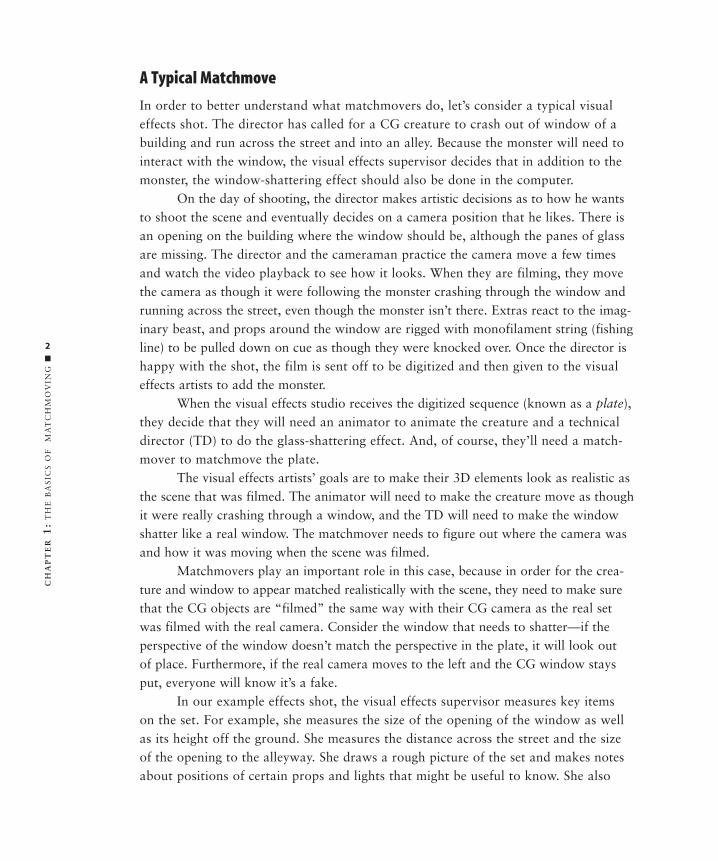
Finally, he saves the scene with the matchmove camera in it. The animator andTD both use this camera to render their animations. If they’ve placed their window andcreature in the right place in the environment, then they don’t need to worry aboutwhether the perspective matches or whether movement of the camera is the same. Aslong as they’ve rendered it using the matchmove camera, it will appear matched intothe footage (Figure 1.1).
Figure 1.1 In the original “clean” plate (left) we see the image before the CG elements are placed in the shot. In the 3D-animation
software, a CG camera is positioned in the environment (middle) in such a way that when the CG vehicle is viewed through it
(right), the perspective matches that of the plate.
4403c01.qxd 1/27/05 12:44 PM Page 3
4
CH
AP
TE
R1
:T
HE
BA
SIC
S O
F
MA
TC
HM
OV
ING
■
From 3D to 2D and Back Again
No discussion of matchmoving would be complete without discussing cameras. For match-movers, it is important to understand how real-world cameras work and how they makethe images we see on the screen. I’ll discuss cameras more in-depth in Chapter 6, “Cam-eras,” but for now there are a few basic concepts about real-world cameras that areimportant to know before getting started.
When a real camera films a scene, it is basically doing one thing: capturing thethree-dimensional world as a two-dimensional image. That is, it gathers light from the3D world around us and records it in a 2D form, such as a piece of film or a digitalimage. Let’s consider for a moment exactly how this happens.
The light from the scene passes through the camera lens and is focused onto filmthat rests in the film gate on the back of the camera’s inner chamber. The shutter closes,the film advances, the shutter opens again, and the process repeats. In the case of digitalcameras, the film and film gate are replaced by a CCD (Charge-Coupled Device) thatelectronically captures the light information and records it to some sort of memory device.
The cameras in a 3D-animation program are based on real cameras, but they are represented in a slightly different manner. 3D-animation cameras represent a math-ematically perfect model of the optics and construction of a real camera. Like real-worldcameras, they have a focal length and a film back (the equivalent of a film gate). Butrather than capturing light from the real world, they are simply capturing informationof the synthetic, computer-generated environment in which they have been placed.
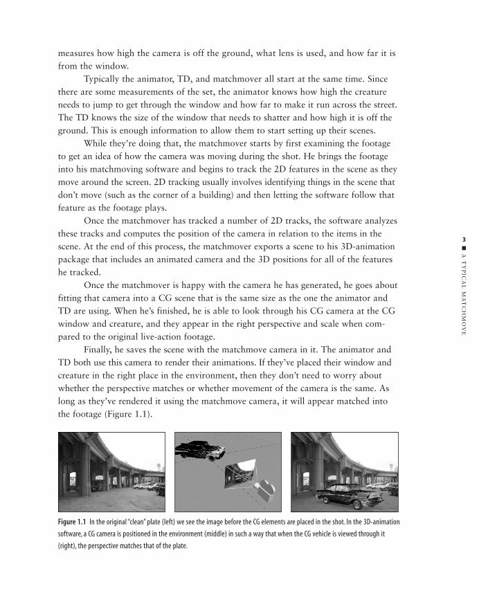
Whether you’re dealing with exposed film or a 3D render, the resulting image isa projection. That is, the three-dimensional scene is flattened out into a two-dimensionalrepresentation of that scene. We have become so accustomed to these flattened imagesthat we hardly notice them anymore, but every time we watch TV or a film, we arewatching a flat recording of a three-dimensional scene (Figure 1.2).
Figure 1.2 When a camera captures
an image of the three-dimensional
world, it is really capturing the light
from the scene that is projected
across its image plane.
4403c01.qxd 1/27/05 12:44 PM Page 4
5
■ T
HE
MA
TC
HM
OV
ING
PR
OC
ES
S
The Matchmoving Process
So if a camera’s purpose is to take the three-dimensional world and make a two-dimensional image, a matchmover’s job is the exact opposite. A matchmover must take a two-dimensional image and create a three-dimensional world. The portal betweenthese two halves is the camera. If information about the camera can be reconstructed, it will go a long way toward figuring out how the 3D environment must have been atthe time of filming. This information—the 3D environment and the camera—is what a matchmover will ultimately deliver to the animators to work with.
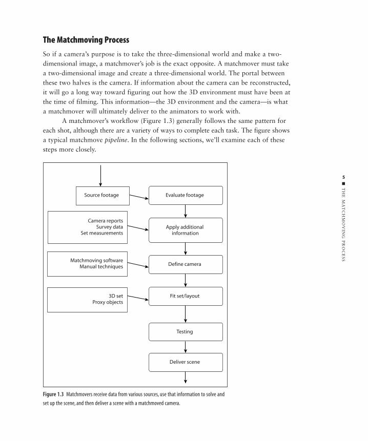
A matchmover’s workflow (Figure 1.3) generally follows the same pattern foreach shot, although there are a variety of ways to complete each task. The figure shows a typical matchmove pipeline. In the following sections, we’ll examine each of thesesteps more closely.
Figure 1.3 Matchmovers receive data from various sources, use that information to solve and
set up the scene, and then deliver a scene with a matchmoved camera.
Evaluate footageSource footage
Camera reportsSurvey data
Set measurements
Matchmoving softwareManual techniques
3D setProxy objects
Define camera
Fit set/layout
Testing
Deliver scene
Apply additional information
4403c01.qxd 1/27/05 12:44 PM Page 5
6
CH
AP
TE
R1
:T
HE
BA
SIC
S O
F
MA
TC
HM
OV
ING
■
Evaluate the Footage
This is perhaps the most important step in the matchmoving process, and unfortunatelyit is often overlooked. There are many ways to solve a matchmove, and careful scrutinyof the plate can help decide the appropriate tool to use, what pitfalls to watch out for,and how long it might take. This last item is particularly important, since clients andsupervisors often put it at the top of their list of questions.
One reason the evaluation process is so often glossed over is that many of thethings that determine the difficulty of matchmove require some experience to judge.Some typical questions asked during the evaluation of a shot could include:
• What does the camera seem to be doing? Is it moving, and if so, how? Is itlocked off or panning? How fast is it moving?
• What is visible in the shot? Are there tracking markers? Is anything blocking the markers?
• What format is the plate? Was it shot on film? DV? HD? Is there excessive compression, grain, or noise on the images?
• What needs to be placed in the shot? How accurate does it have to be?
• Who will be using the matchmove, and how will they be using it?
Of course, these only scratch the surface, but the more questions you ask, themore you will know what you need to do. The tutorials in this book are designed tohelp you learn what these key questions are and how to deal with their implications. Amore thorough list of questions are included in Appendix A. The Evaluation Checklistthere can be used as a guideline to help determine the difficulty of a matchmove.
Applying Information
As I’ve said, solving a matchmove can be like solving a puzzle (it’s no coincidence thatit’s referred to as “solving” a matchmove). And as such, the more information there is,the easier it should be to achieve good results.
The amount of information given to matchmovers can run the gamut. Theremight only be an image sequence and nothing else, or perhaps someone was allowedon set to record all the camera information and take measurements. Usually it’s some-where in between. But the good news is that a surprisingly small amount of data cango a long way toward solving the matchmove.
The following are typical data a matchmover might include:
Camera information Such as focal length, aperture, and film type.
Set measurements Including camera height, focus distance, and measurements of vari-ous items in the shot.
Survey data This is very detailed measuring of the set, usually done by a professionalsurveyor.
4403c01.qxd 1/27/05 12:44 PM Page 6
7
■ T
HE
MA
TC
HM
OV
ING
PR
OC
ES
S
Define the Camera
As stated before, the matchmover’s job is to define all of the internal and externalparameters of the camera, and there are many ways to do that. Knowing which methodto use and under what circumstances comes with experience, but sometimes the onlyway to solve the matchmove is to experiment and see what works best. In broad terms,there are two major ways of solving for the camera: manual and automatic.
The manual methods harken back to the days before software existed to helpmatchmovers. This category would include perspective matching (matching the perspec-tive of a single background image, rather than an image sequence, which is covered laterin this chapter) and old-fashioned hand-tracking. This method of tracking a sequenceinvolves making a speculation as to the camera’s position and then refining it overmany iterations until a match is achieved. Tracking a camera by hand is no small feat.It can often take weeks to truly figure out what is happening, because the process isnothing more than making educated guesses and tweaking them until they work.
In the past five or six years, software has emerged that allows a matchmover totrack cameras somewhat automatically using a sophisticated technology known as pho-togrammetry. These software packages (which are covered in the next chapter) usuallyhave a similar workflow to them. First, features in the image such as props in the sceneor tape markers (commonly used on blue screen footage to mark points on the wall)are “tracked” as they move around the image in 2D. Then the software performs a cal-ibration (or solve) for the camera by mathematically analyzing the movements of the2D tracking markers. These packages usually generate an animated camera and 3Dmarkers or nulls that represent the three-dimensional location of features that havebeen tracked in 2D. Matchmovers use this method most often since it is the easiest wayto achieve a solution.
Some methods borrow from both manual and automatic techniques. Oftentimes,these are customized solutions that revolve around both types of workflows. For example,the 2D tracking information from matchmoving software could be used with a customscript that allows the matchmover to solve for pan shots.
Set Fitting
While cameras are the primary concern, they are only half of the process of matchmov-ing. Matchmovers must not only uncover all the facts about the camera, but they mustalso reconstruct the spatial layout of the environment on the live-action plate.
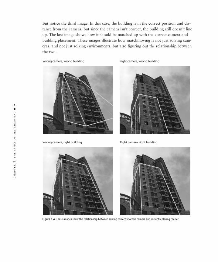
Figure 1.4 shows why this information is important. The first image shows anincorrect camera and building placement—what a mess. The second image has thecorrect camera, but the building is too close to the camera; therefore it doesn’t match.
4403c01.qxd 1/27/05 12:44 PM Page 7
8
CH
AP
TE
R1
:T
HE
BA
SIC
S O
F
MA
TC
HM
OV
ING
■
But notice the third image. In this case, the building is in the correct position and dis-tance from the camera, but since the camera isn’t correct, the building still doesn’t lineup. The last image shows how it should be matched up with the correct camera andbuilding placement. These images illustrate how matchmoving is not just solving cam-eras, and not just solving environments, but also figuring out the relationship betweenthe two.
Figure 1.4 These images show the relationship between solving correctly for the camera and correctly placing the set.
Right camera, right buildingWrong camera, right building
Right camera, wrong buildingWrong camera, wrong building
4403c01.qxd 1/27/05 12:44 PM Page 8
9
■ T
HE
MA
TC
HM
OV
ING
PR
OC
ES
S
How much of the environment does the matchmover need to reproduce? Thatdepends on what is being placed into the footage. If it is simply a character walking by, the animators and TDs might only need a simple ground plane. Other scenes mightneed rough geometry in order to cast 3D shadows. In some cases, such as digital setextensions, the matchmove might require an extremely accurate camera, detailed geom-etry, and spot-on positioning. Before beginning a matchmove, it is important to findout what type of 3D object is going into the scene and exactly where it will be placed.
3D environments might come from a variety of sources. Oftentimes, match-movers create the rough geometry themselves or are provided a set to “fit” into theplate. And in some situations, the matchmover may provide a rough set from which amore detailed set is later constructed by a modeler. Many times, matchmovers use 3Dmarkers they’ve calculated during the matchmove to provide information about thespatial relationships of the scene. But regardless of where the information comes from,it is often the matchmover’s responsibility to establish the environment and set up thescene so that other artists further down the production pipeline don’t need to worryabout it.
Testing the Matchmove
Once the matchmove is solved, it needs to be tested for accuracy. A bad matchmoveusually shows up as an obvious disconnect between the live-action plate and the CGelements. For example, the CG element seems to follow the motion and rotation of thelive-action scene, but then suddenly the CG element pops to another location or gradu-ally drifts away from the feature it’s supposed to be resting on. Testing the matchmoveconsists of compositing the 3D objects over the image sequence and watching as thesequence moves to see if there are any unusual pops, drifts, or jitter.
Most often, matchmovers will have low-resolution objects, or proxy objects, inthe scene to help them determine the quality of their matchmove. One of the best waysto see if an object is slipping is to place a checkerboard texture on it and render it out.This will help highlight slippage in 3D space.
A thorough testing is crucial, because a bad matchmove conceivably could workits way all the way through the pipeline and not be noticed until the end. And by thistime there is usually a lot less time to deal with the problem and a lot more pressure.
Delivering the Scene
Last but not least, the final scene is delivered to other artists down the line. This stepwill vary greatly depending on whether the scene goes to a single artist working alone,or the scene is being turned over in a large production pipeline.
4403c01.qxd 1/27/05 12:44 PM Page 9
10
CH
AP
TE
R1
:T
HE
BA
SIC
S O
F
MA
TC
HM
OV
ING
■
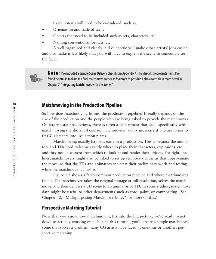
Certain items will need to be considered, such as:
• Orientation and scale of scene
• Objects that need to be included such as sets, characters, etc.
• Naming conventions, formats, etc.A well-organized and clearly laid-out scene will make other artists’ jobs easier
and also make it less likely that you will have to explain the scene to someone afterthe fact.
Matchmoving in the Production Pipeline
So how does matchmoving fit into the production pipeline? It really depends on thesize of the production and the people who are being asked to provide the matchmoves.On larger-scale productions, there is often a department that deals specifically withmatchmoving the shots. Of course, matchmoving is only necessary if you are trying tofit CG elements into live-action plates.
Matchmoving usually happens early in a production. This is because the anima-tors and TDs need to know exactly where to place their characters, explosions, etc.,and they need a camera from which to look at and render their objects. For tight dead-lines, matchmovers might also be asked to set up temporary cameras that approximatethe move, so that the TDs and animators can start their preliminary work and testingwhile the matchmove is finished.
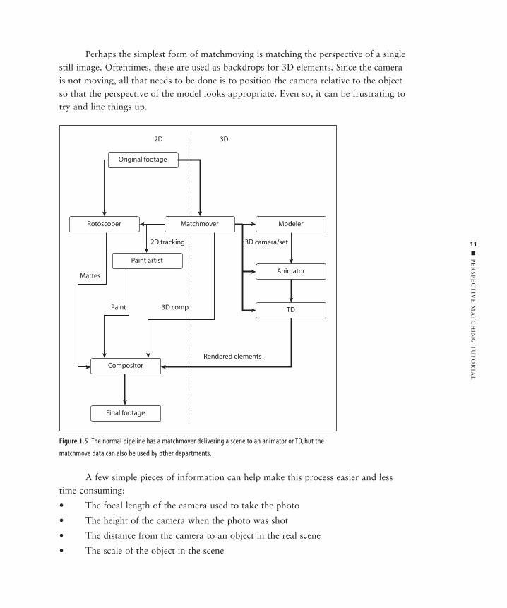
Figure 1.5 shows a fairly common production pipeline and where matchmovingfits in. The matchmover takes the original footage at full resolution, solves the match-move, and then delivers a 3D scene to an animator or TD. In some studios, matchmovedata might be useful to other departments such as roto, paint, or compositing. (SeeChapter 12, “Multipurposing Matchmove Data,” for more on this.)
Perspective Matching Tutorial
Now that you know how matchmoving fits into the big picture, we’re ready to getdown to actually working on a shot. In this tutorial, you’ll create a simple matchmovescene that solves a problem many CG artists have faced at one time or another: per-spective matching.
N o t e : I’ve included a sample Scene Delivery Checklist in Appendix A.This checklist represents items I’ve
found helpful in making my final matchmove scenes as foolproof as possible. I also cover this in more detail in
Chapter 7,“Integrating Matchmoves with the Scene.”
4403c01.qxd 1/27/05 12:44 PM Page 10
11
■ P
ER
SP
EC
TIV
E M
AT
CH
ING
TU
TO
RIA
L
Perhaps the simplest form of matchmoving is matching the perspective of a singlestill image. Oftentimes, these are used as backdrops for 3D elements. Since the camerais not moving, all that needs to be done is to position the camera relative to the objectso that the perspective of the model looks appropriate. Even so, it can be frustrating totry and line things up.
Figure 1.5 The normal pipeline has a matchmover delivering a scene to an animator or TD, but the
matchmove data can also be used by other departments.
A few simple pieces of information can help make this process easier and lesstime-consuming:
• The focal length of the camera used to take the photo
• The height of the camera when the photo was shot
• The distance from the camera to an object in the real scene
• The scale of the object in the scene
Original footage
Rotoscoper
Paint artist
Compositor
Final footage
Matchmover Modeler
Animator
TD
2D tracking
Mattes
Paint 3D comp
3D camera/set
Rendered elements
2D 3D
4403c01.qxd 1/27/05 12:44 PM Page 11
12
CH
AP
TE
R1
:T
HE
BA
SIC
S O
F
MA
TC
HM
OV
ING
■
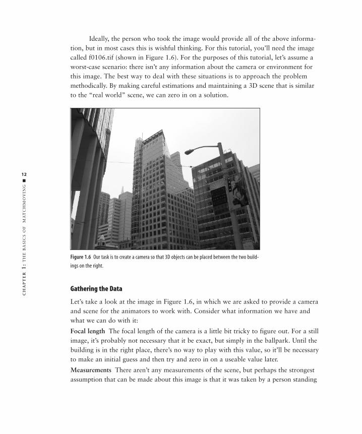
Ideally, the person who took the image would provide all of the above informa-tion, but in most cases this is wishful thinking. For this tutorial, you’ll need the imagecalled f0106.tif (shown in Figure 1.6). For the purposes of this tutorial, let’s assume aworst-case scenario: there isn’t any information about the camera or environment forthis image. The best way to deal with these situations is to approach the problemmethodically. By making careful estimations and maintaining a 3D scene that is similarto the “real world” scene, we can zero in on a solution.
Figure 1.6 Our task is to create a camera so that 3D objects can be placed between the two build-
ings on the right.
Gathering the Data
Let’s take a look at the image in Figure 1.6, in which we are asked to provide a cameraand scene for the animators to work with. Consider what information we have andwhat we can do with it:
Focal length The focal length of the camera is a little bit tricky to figure out. For a stillimage, it’s probably not necessary that it be exact, but simply in the ballpark. Until thebuilding is in the right place, there’s no way to play with this value, so it’ll be necessaryto make an initial guess and then try and zero in on a useable value later.
Measurements There aren’t any measurements of the scene, but perhaps the strongestassumption that can be made about this image is that it was taken by a person standing
4403c01.qxd 1/27/05 12:44 PM Page 12
13
■ P
ER
SP
EC
TIV
E M
AT
CH
ING
TU
TO
RIA
L
at street level. Therefore, it’s reasonable to assume that the camera is a little less than 2 meters off the ground.
Distance We don’t have any idea of the distance to the buildings or the scale of thebuildings themselves. If we were given a model that was based on the blueprints of the building, we would have some solid data to work with, but since we don’t, we’llhave to make a guess at this as well.
Setting Up the Camera
As is often the case with a matchmove, the process is not a linear one. Usually, it is aniterative one, where we do one or two things to get a rough result and then make a fewmore passes to refine it and build on known facts, until at some point we have matchedit to the required level of accuracy. This example is no exception. Below, I show thesteps to get the building matched.
1. Evaluate the scene. Since we’re not dealing with images in motion, the key thingto figure out when matching the perspective of an image is where your 3D mod-els need to go. Let’s say that we want a spaceship to fly in between these twobuildings and cast shadows on them as it goes by. That means we need to knowthe camera’s position as well as the position of each of the buildings.
2. Make a camera and create an image plane or background image using the stillimage. First we need a camera to work with. This should be a freely movingcamera (as opposed to a targeted or aimed camera). Since the ultimate goal is to align the objects with the plate, we will need to set up the camera or environ-ment so that the image is seen as a backdrop behind the 3D objects when welook through the camera.
3. Estimate focal length and aperture on the camera. The two main things we’llneed to know for the camera setup are the focal length and the film back. Aswe’ve already covered, we don’t know the exact value for this lens, so we’ll haveto guess. I took a guess of 35mm for this lens as a starting point.
4. Estimate the film back value. In this case, I don’t know the specific value forthe film back. If I knew the brand of camera, I could look up the specs for it on the Internet and plug in those values. If you don’t know the film back, it’s
N o t e : This book uses metric measurements, because that is the standard practice in most studios.
4403c01.qxd 1/27/05 12:44 PM Page 13
14
CH
AP
TE
R1
:T
HE
BA
SIC
S O
F
MA
TC
HM
OV
ING
■
best to go with a standard value of 0.980″ × 0.735″ or use the default settingsin your animation program. The reasons for these values are a bit complicated,so I’ll save the explanation for Chapter 6, but for now this will give us some-thing to work with.
5. Set the height of the camera. Since this is the strongest assumption we can makeabout the camera, we’ll enter it in first. We’ll assume an average height for thecamera of about 1.75 meters off the ground, so place the camera at 1.75m up onthe Y-axis.
Not All Film Backs Are the Same
Don’t worry if you find yourself a little bit confused by all of this film back business. It can bewildereven the most seasoned visual effects pros. Oftentimes, 3D artists just guess at the value or usepreset values in the software.
To make matters even more confusing, every 3D animation and matchmove program uses differentterminology and has different ways of entering the information. Matchmove programs use theterm “film back,” whereas most 3D animation programs call this the “aperture.” For example, 3DStudio Max calls it the Horizontal Aperture and only allows you to enter the horizontal measure-ment in millimeters. Lightwave uses the Vertical Aperture only, and Maya allows you to enter bothHorizontal and Vertical Aperture measurements, but only in inches! You should consult the docu-mentation for your software to see where you need to enter this information and how.
Adding Rough Geometry and Refining the Camera
Now that we have a camera set up, we need to start fleshing out the geometry in thescene. When the animators get ready to put the UFO in between the buildings, they’llneed to know where the buildings are. The task of identifying the location of objects inthe scene often falls on the shoulders of matchmovers. This geometry needs to be accu-rate to the image so that any additional objects that are added to the scene will appearto be in the correct location. You usually don’t need to build geometry for the entirescene, just the portions that will interact directly with the CG objects.
I’ve found that creating geometry for a scene can be done in conjunction withthe initial camera setup. Often you’ll need to make continual refinements to the cameraand geometry until you’ve zeroed in on the correct placement for both. The good newsis, once you’ve built one or two objects, the rest become much simpler to build. Also,
4403c01.qxd 1/27/05 12:44 PM Page 14
15
■ P
ER
SP
EC
TIV
E M
AT
CH
ING
TU
TO
RIA
L
once you’ve built objects to work with, you’ll find it much easier to find the camera’sexact position.
1. Create a building of an estimated height. This is where it starts to get tricky,since we really have little to go on here. I estimated the size by looking at thewindows. I figured that each floor of the building was about 4 meters tall. So Icounted the number of floors and multiplied it by 4m. I guessed that the build-ing was a little under 14 floors, so 55 meters seemed about right. Likewise, Itried to use visual clues to estimate the width and depth of the building. Aftermy initial guess, I came up with values for my building of X = 16.5m, Y = 55m,and Z = 20m.
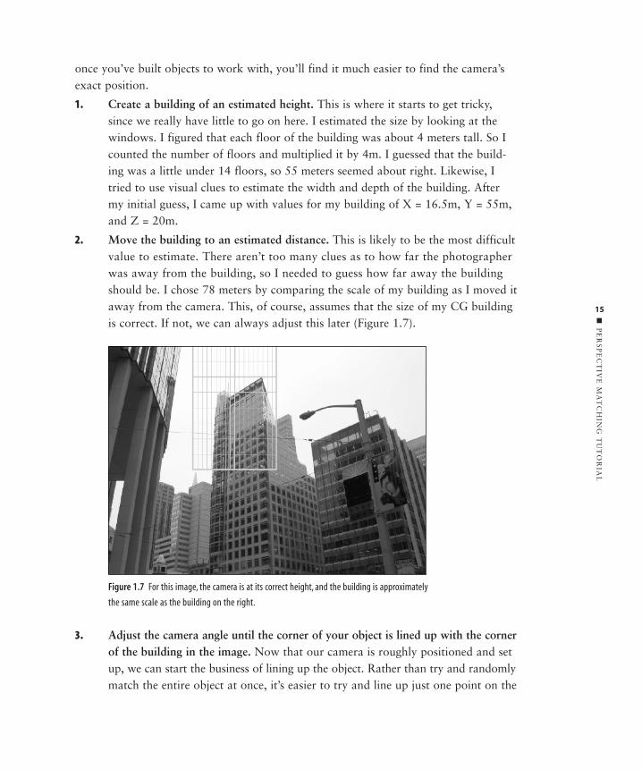
2. Move the building to an estimated distance. This is likely to be the most difficultvalue to estimate. There aren’t too many clues as to how far the photographerwas away from the building, so I needed to guess how far away the buildingshould be. I chose 78 meters by comparing the scale of my building as I moved itaway from the camera. This, of course, assumes that the size of my CG buildingis correct. If not, we can always adjust this later (Figure 1.7).
Figure 1.7 For this image, the camera is at its correct height, and the building is approximately
the same scale as the building on the right.
3. Adjust the camera angle until the corner of your object is lined up with the cornerof the building in the image. Now that our camera is roughly positioned and setup, we can start the business of lining up the object. Rather than try and randomlymatch the entire object at once, it’s easier to try and line up just one point on the
4403c01.qxd 1/27/05 12:44 PM Page 15
16
CH
AP
TE
R1
:T
HE
BA
SIC
S O
F
MA
TC
HM
OV
ING
■
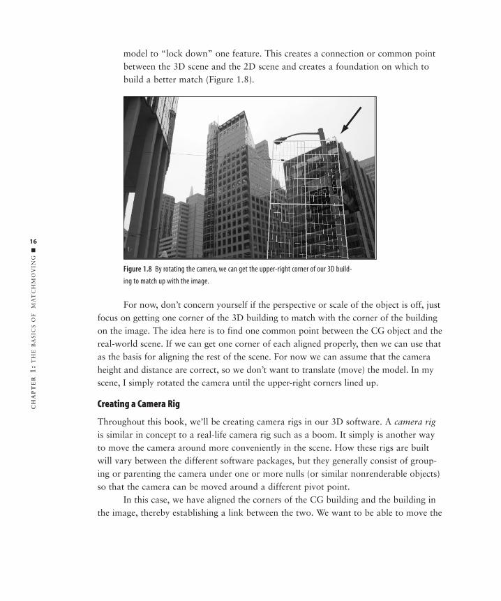
model to “lock down” one feature. This creates a connection or common pointbetween the 3D scene and the 2D scene and creates a foundation on which tobuild a better match (Figure 1.8).
Figure 1.8 By rotating the camera, we can get the upper-right corner of our 3D build-
ing to match up with the image.
For now, don’t concern yourself if the perspective or scale of the object is off, justfocus on getting one corner of the 3D building to match with the corner of the buildingon the image. The idea here is to find one common point between the CG object and thereal-world scene. If we can get one corner of each aligned properly, then we can use thatas the basis for aligning the rest of the scene. For now we can assume that the cameraheight and distance are correct, so we don’t want to translate (move) the model. In myscene, I simply rotated the camera until the upper-right corners lined up.
Creating a Camera Rig
Throughout this book, we’ll be creating camera rigs in our 3D software. A camera rigis similar in concept to a real-life camera rig such as a boom. It simply is another wayto move the camera around more conveniently in the scene. How these rigs are builtwill vary between the different software packages, but they generally consist of group-ing or parenting the camera under one or more nulls (or similar nonrenderable objects)so that the camera can be moved around a different pivot point.
In this case, we have aligned the corners of the CG building and the building inthe image, thereby establishing a link between the two. We want to be able to move the
4403c01.qxd 1/27/05 12:44 PM Page 16
17
■ P
ER
SP
EC
TIV
E M
AT
CH
ING
TU
TO
RIA
L
camera while maintaining that alignment, so we’ll create a rig that does exactly that.Here are the steps to create and position a camera rig:
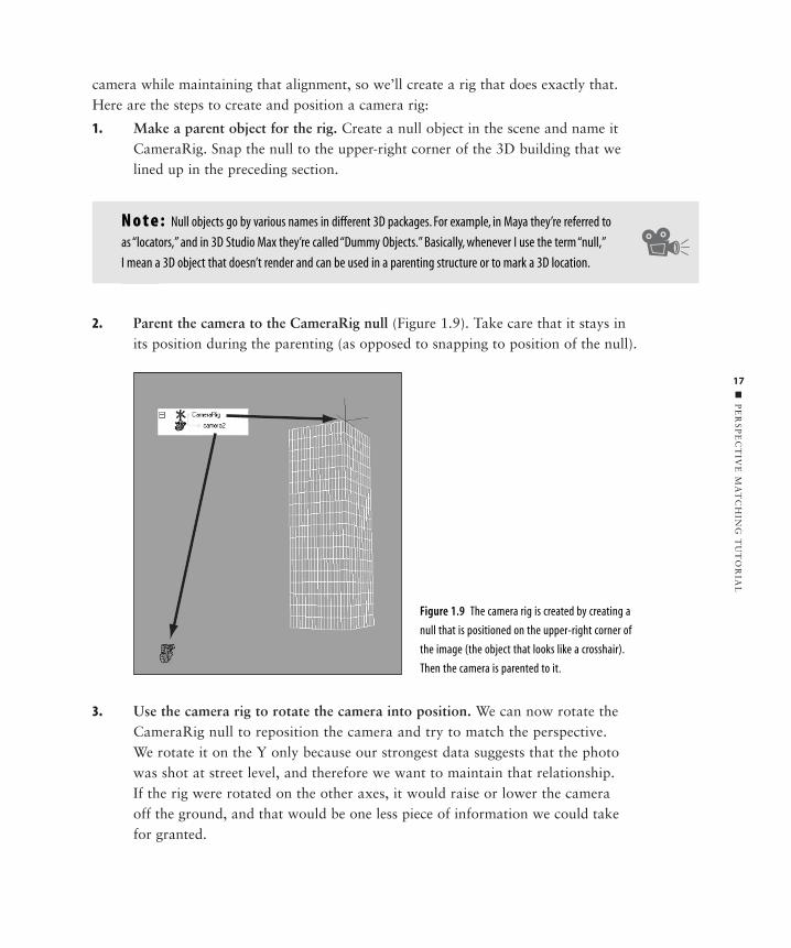
1. Make a parent object for the rig. Create a null object in the scene and name itCameraRig. Snap the null to the upper-right corner of the 3D building that welined up in the preceding section.
2. Parent the camera to the CameraRig null (Figure 1.9). Take care that it stays inits position during the parenting (as opposed to snapping to position of the null).
3. Use the camera rig to rotate the camera into position. We can now rotate theCameraRig null to reposition the camera and try to match the perspective. We rotate it on the Y only because our strongest data suggests that the photowas shot at street level, and therefore we want to maintain that relationship. If the rig were rotated on the other axes, it would raise or lower the camera off the ground, and that would be one less piece of information we could takefor granted.
Figure 1.9 The camera rig is created by creating a
null that is positioned on the upper-right corner of
the image (the object that looks like a crosshair).
Then the camera is parented to it.
N o t e : Null objects go by various names in different 3D packages. For example, in Maya they’re referred to
as “locators,” and in 3D Studio Max they’re called “Dummy Objects.” Basically, whenever I use the term “null,”
I mean a 3D object that doesn’t render and can be used in a parenting structure or to mark a 3D location.
4403c01.qxd 1/27/05 12:44 PM Page 17
18
CH
AP
TE
R1
:T
HE
BA
SIC
S O
F
MA
TC
HM
OV
ING
■
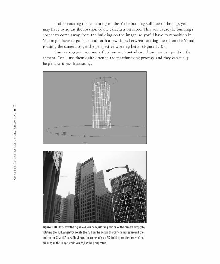
If after rotating the camera rig on the Y the building still doesn’t line up, youmay have to adjust the rotation of the camera a bit more. This will cause the building’scorner to come away from the building on the image, so you’ll have to reposition it.You might have to go back and forth a few times between rotating the rig on the Y androtating the camera to get the perspective working better (Figure 1.10).
Camera rigs give you more freedom and control over how you can position thecamera. You’ll use them quite often in the matchmoving process, and they can reallyhelp make it less frustrating.
Figure 1.10 Note how the rig allows you to adjust the position of the camera simply by
rotating the null. When you rotate the null on the Y-axis, the camera moves around the
null on the X- and Z-axes. This keeps the corner of your 3D building on the corner of the
building in the image while you adjust the perspective.
4403c01.qxd 1/27/05 12:44 PM Page 18
19
■ P
ER
SP
EC
TIV
E M
AT
CH
ING
TU
TO
RIA
L
Evaluating and Adjusting the Camera
Up until this point, we’ve been working with approximations for our camera andbuilding. Now we have everything we need to “tighten” up the matchmove and findthe exact settings for the camera and the right size and shape for the building. In thisphase, we are trying to bring the scene into perfect alignment.
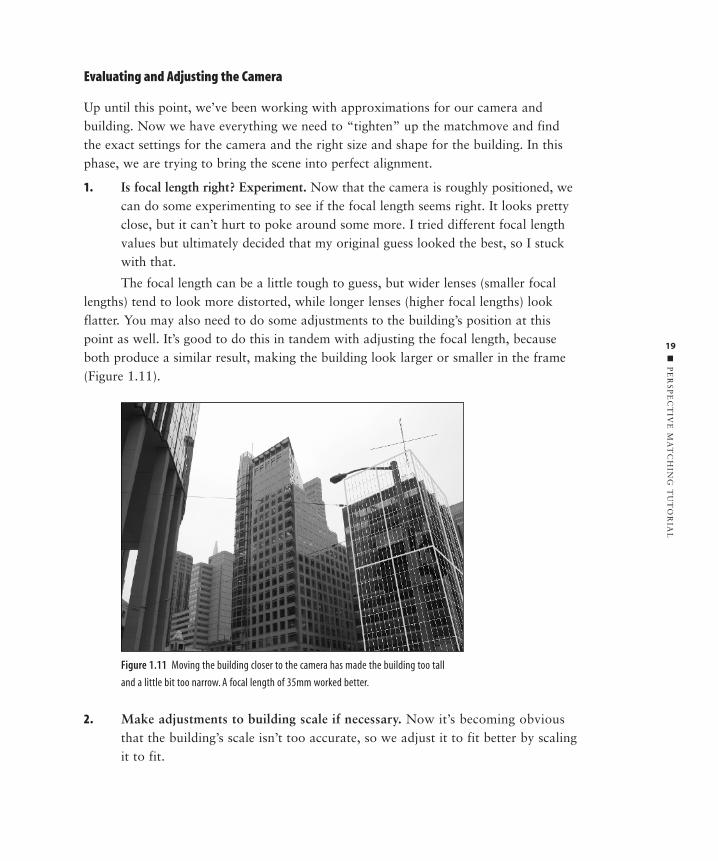
1. Is focal length right? Experiment. Now that the camera is roughly positioned, wecan do some experimenting to see if the focal length seems right. It looks prettyclose, but it can’t hurt to poke around some more. I tried different focal lengthvalues but ultimately decided that my original guess looked the best, so I stuckwith that.
The focal length can be a little tough to guess, but wider lenses (smaller focallengths) tend to look more distorted, while longer lenses (higher focal lengths) lookflatter. You may also need to do some adjustments to the building’s position at thispoint as well. It’s good to do this in tandem with adjusting the focal length, becauseboth produce a similar result, making the building look larger or smaller in the frame(Figure 1.11).
Figure 1.11 Moving the building closer to the camera has made the building too tall
and a little bit too narrow. A focal length of 35mm worked better.
2. Make adjustments to building scale if necessary. Now it’s becoming obviousthat the building’s scale isn’t too accurate, so we adjust it to fit better by scalingit to fit.
4403c01.qxd 1/27/05 12:44 PM Page 19
20
CH
AP
TE
R1
:T
HE
BA
SIC
S O
F
MA
TC
HM
OV
ING
■
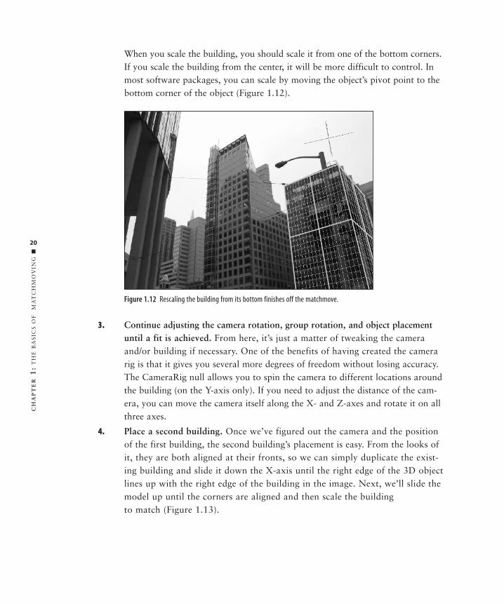
When you scale the building, you should scale it from one of the bottom corners.If you scale the building from the center, it will be more difficult to control. Inmost software packages, you can scale by moving the object’s pivot point to thebottom corner of the object (Figure 1.12).
Figure 1.12 Rescaling the building from its bottom finishes off the matchmove.
3. Continue adjusting the camera rotation, group rotation, and object placementuntil a fit is achieved. From here, it’s just a matter of tweaking the cameraand/or building if necessary. One of the benefits of having created the camera rig is that it gives you several more degrees of freedom without losing accuracy.The CameraRig null allows you to spin the camera to different locations aroundthe building (on the Y-axis only). If you need to adjust the distance of the cam-era, you can move the camera itself along the X- and Z-axes and rotate it on allthree axes.
4. Place a second building. Once we’ve figured out the camera and the positionof the first building, the second building’s placement is easy. From the looks ofit, they are both aligned at their fronts, so we can simply duplicate the exist-ing building and slide it down the X-axis until the right edge of the 3D objectlines up with the right edge of the building in the image. Next, we’ll slide themodel up until the corners are aligned and then scale the building to match (Figure 1.13).
4403c01.qxd 1/27/05 12:44 PM Page 20
21
■ P
ER
SP
EC
TIV
E M
AT
CH
ING
TU
TO
RIA
L
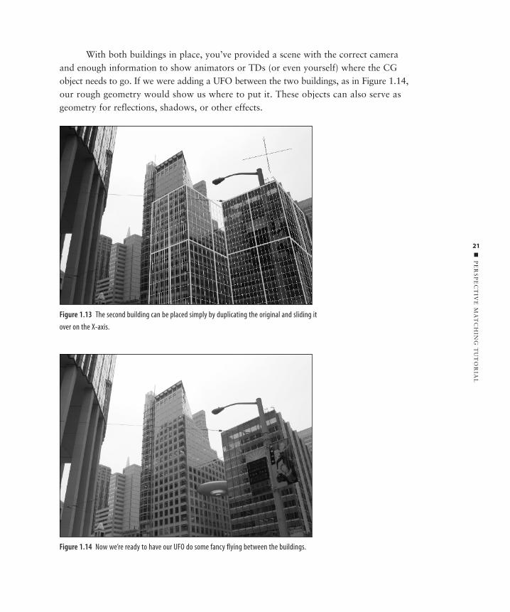
With both buildings in place, you’ve provided a scene with the correct cameraand enough information to show animators or TDs (or even yourself) where the CGobject needs to go. If we were adding a UFO between the two buildings, as in Figure 1.14,our rough geometry would show us where to put it. These objects can also serve asgeometry for reflections, shadows, or other effects.
Figure 1.13 The second building can be placed simply by duplicating the original and sliding it
over on the X-axis.
Figure 1.14 Now we’re ready to have our UFO do some fancy flying between the buildings.
4403c01.qxd 1/27/05 12:44 PM Page 21

22
CH
AP
TE
R1
:T
HE
BA
SIC
S O
F
MA
TC
HM
OV
ING
■
Moving Toward Moving Pictures
So as you can see, matchmoving doesn’t have to be a completely blind process of ran-dom guesses. By building on the information at hand, you can infer the informationyou don’t have. Although we are working on a still image here, the same techniquescan be applied to a moving sequence as well.
This method works well for these relatively simple still image situations, but formore complicated shots, it is useful to enlist the help of matchmoving software. Startingwith the next chapter, I cover how these programs work, and how they can be usedeffectively to help solve even the toughest shots.
4403c01.qxd 1/27/05 12:44 PM Page 22