the basics of laser-cutting - fablab maastricht
TRANSCRIPT

The Basics of Laser-Cutting
Laser‐cutting delivers results that are, in many cases, faster and more accurate than traditional methods. Understanding some background information on how the process works, plus knowing a few tricks, will help you make the most of the technology.
Figure 1. One of the Design Lab's laser‐cutters. Contents
1. How the process works.
2. Is the laser the right choice? 2.1 Objects that can be cut, and ones that can’t
2.2 Selecting material for cutting
3. Supplying design information. 3.1 Drawing ’laser‐friendly’ CAD
3.2 What to keep and what not to keep
4. Ordering and payment 4.0 How much will it cost?
4.1 When things go wrong
4.2 Order confirmation and payment
4.3 The queuing system
Figure 2. Sheet material being cut.

1. How the process works
Imagine taking a really small blow‐torch and attaching it to a mechanical arm controlled by a computer – that, in its most basic form, is laser‐cutting. What we’re talking about is, essentially, a controlled way to burn through various materials. We’re deliberately using the term ‘burn’ because heat, flame, smoke and fumes are constant side effects of the laser‐cutting process – which, if not handled correctly, will cause problems for the job being cut, the person operating the system and the cutting equipment itself.
The process starts with a sheet of material being laid flat on a perforated table inside of the laser cabinet (see figs.1&2). The lid of the machine is then closed. Next, a CAD file is loaded into the software that controls the position of the laser and the laser beam itself is turned on. Before the actual cutting begins, an extraction system is activated, causing air to flow into the chamber, around the material and out again helping to control the flame, smoke and fumes mentioned above. Cutting then takes place and, on completion, the material is removed from the machine ready for collection.
2.0 Is the laser the right choice? Used for certain types of work, laser‐cutting is undoubtedly the best option – however, it is not always going to be the ideal solution. There are a number of factors to be considered when deciding whether or not to use the laser.
2.1 Objects that can be cut, and ones that can’t.
The laser is designed to work with objects that are flat in shape, and no more than 12mm in thickness. Objects that do not fit this category need a different approach – consult either your tutors or Digital Workshop staff for more information.
2.2 Selecting material for cutting.
The Digital Workshop groups materials into those that can be laser‐cut safely with its equipment and those that can’t. Materials that don’t cut safely usually produce dangerous/toxic fumes or have a high fire‐risk and therefore present a danger to staff and/or equipment. The workshop will not laser‐cut these materials at any time! If you intend to supply a material for cutting that is not included on the list of the ones commonly used by the Digital Workshop(see figure 3.) you should check in advance with staff that you are making a suitable choice. To help with this, you should obtain a Material Safety Data Sheet (MSDS) and a small sample from the material supplier – this will show technical information on the material and help Digital Workshop staff to evaluate it. Of the materials that can be cut, some work better than others in terms of the quality of the result. If you wish to use a material that won’t cut well, you will be advised of this by staff and the decision to proceed will be yours to make (on the understanding that you will not give given any refund if you are unhappy with the results).

Figure 3.
Materials commonly used by the Digital Workshop for Laser‐cutting
Material Cutting Quality Usually Stocked Sheet Size (mm) Thickness (mm) Porous(may stain)*
Clear Acrylic Excellent Yes 800 x 600 1.5, 2.0, 3.0, 4.5, 6.0 No
Coloured Acrylic Excellent No No
Paste board (white) Very Good Yes 900 x 600 1.0 Yes
Boxboard (Grey) Very Good Yes 900 x 600 1.2, 1.8 Yes
Medium Density Fibreboard (MDF) Good Yes 800 x 600 3.0, 6.0 Yes
Plywood Fair No Yes
*Smoke from the laser process can stain some porous materials – for an additional charge, the Digital Workshop can apply a protective masking film to prevent this.
If you want to supply your own material, check the Yellow Pages or internet for suppliers. Figure 4 lists a variety of suppliers used by the Digital Workshop.
Figure 4.
Materials suppliers used by the Digital Workshop
Material Company Location Phone
Acrylic Plastix Princes Highway, Arncliffe 9599 2499
Mulford Plastics Holker Street, Silverwater 9911 8111
FX Plastics Sydenham Road, Marrickville 9550 5844
All Plastics Eastern Valley Way, Chatswood 1300 792 481
Paste board & Box board Oxford Art Oxford Street, Darlinghurst 9360 4066
(MDF) & Plywood Mr Ply & Wood McEvoy Street, Alexandria 9557 7122
Bunnings Bourke Road, Mascot 9700 8599

3.0 Supplying design information.
Chances are, that by the time you’re ready to get something laser‐ cut, you’re going to be very familiar with the subject of your project and all the reasoning behind it. To ensure that Digital Workshop staff (who have no prior knowledge of your project) and the laser equipment (which is high‐tech, but not telepathic) properly understands what you want, you will need to supply your information in a way that meets certain rules.
3.1 Drawing ‘laser‐friendly’ CAD.
File types & existing drawings. Use the Adobe Illustrator (.ai) file format. Files created in other software packages should be converted to this format.
If you have existing drawings, you will probably need to edit them before they will work with the laser. The laser is not smart enough to know which lines on a drawing are the ones you want to cut as opposed to those that you don’t ‐ if the laser can see a line on your drawing, it’s going to cut it (dimension lines included)! To fix this, create a separate CAD file for your laser‐cutting and delete any lines that you don’t want cut.
Page size: The lasers used by the Digital Workshop can cut a sheet of material up to a size of 900mm long by 600mm wide in a Landscape format. Make your drawing page this size even if you will only be drawing on a portion of it. Failing to do this may result in scaling problems when your file is opened by the Digital Workshop. Also consider the available sheet size of the material you will be using when positioning your design elements on the page – there’s not much point in spreading them out to the full extent of the 900mm by 600mm page area if the only material you can buy is 700mm by 500mm. If the Digital Workshop is supplying the material, you can check with the table in this document (figure 3.) for the range of available sizes.
Colour model: Use an RGB colour model for your drawings, other colour models will not work with the laser software.
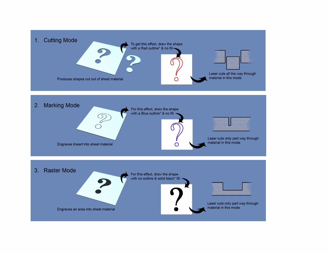
Line colour and weight: The laser can cut in three different modes, each of which produces a different result (see the following diagrams). By giving different combinations of outline and fill to your drawing, you tell the laser which of these modes to use. The colours used are pure RGB Red (255,000,000) pure RGB Blue (000,000,255) and RGB Black (000,000,000). Using other colours will cause problems. In all cases, the line weight should be set to 0.001mm (0.025 points). Helpful hint – when setting line weight in Adobe Illustrator you will have to key‐in these values manually as the available pre‐sets in the drop‐down box do not go this low.
Polylines: Try to use polylines for drawing rather than individual line segments – this usually results in faster cutting times.
Layers: Make sure that each CAD file you submit for laser‐cutting has only one layer.

Draw connecting tabs: If your design has a lot of small pieces, there’s a good chance that a few of these will get lost somewhere between picking them up from the laser and getting them home. Also, because the table that supports the material in the laser is perforated, there’s the possibility of pieces falling through it and getting lost. This problem can be solved as shown below. Draw the gaps around 1.5mm wide.
Duplicate lines: When drawing CAD, you sometimes end up with multiple copies of lines directly on top of each other. The diagram below shows why this is a problem ‐ and gives a solution for it.
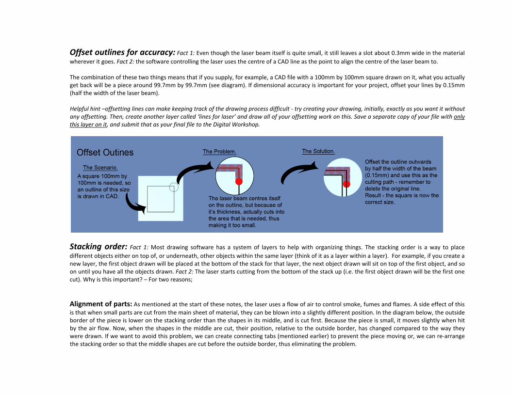
Offset outlines for accuracy: Fact 1: Even though the laser beam itself is quite small, it still leaves a slot about 0.3mm wide in the material wherever it goes. Fact 2: the software controlling the laser uses the centre of a CAD line as the point to align the centre of the laser beam to. The combination of these two things means that if you supply, for example, a CAD file with a 100mm by 100mm square drawn on it, what you actually get back will be a piece around 99.7mm by 99.7mm (see diagram). If dimensional accuracy is important for your project, offset your lines by 0.15mm (half the width of the laser beam). Helpful hint –offsetting lines can make keeping track of the drawing process difficult ‐ try creating your drawing, initially, exactly as you want it without any offsetting. Then, create another layer called ‘lines for laser’ and draw all of your offsetting work on this. Save a separate copy of your file with only this layer on it, and submit that as your final file to the Digital Workshop.
Stacking order: Fact 1: Most drawing software has a system of layers to help with organizing things. The stacking order is a way to place different objects either on top of, or underneath, other objects within the same layer (think of it as a layer within a layer). For example, if you create a new layer, the first object drawn will be placed at the bottom of the stack for that layer, the next object drawn will sit on top of the first object, and so on until you have all the objects drawn. Fact 2: The laser starts cutting from the bottom of the stack up (i.e. the first object drawn will be the first one cut). Why is this important? – For two reasons; Alignment of parts: As mentioned at the start of these notes, the laser uses a flow of air to control smoke, fumes and flames. A side effect of this is that when small parts are cut from the main sheet of material, they can be blown into a slightly different position. In the diagram below, the outside border of the piece is lower on the stacking order than the shapes in its middle, and is cut first. Because the piece is small, it moves slightly when hit by the air flow. Now, when the shapes in the middle are cut, their position, relative to the outside border, has changed compared to the way they were drawn. If we want to avoid this problem, we can create connecting tabs (mentioned earlier) to prevent the piece moving or, we can re‐arrange the stacking order so that the middle shapes are cut before the outside border, thus eliminating the problem.

Heat distortion: Laser‐cutting generates heat in the material as it cuts. This heat will gradually be lost, unless the laser beam returns to that area again before the cooling process has finished – in which case, heat will build up in that area. With some materials, this is not a concern – with others, such as acrylic (a thermoplastic), it can be a big problem because the excess heat will cause some parts to distort (see diagram). Generally, the problem is greatest in places where laser‐cutting leaves a narrow strip of material, the width of which is about the same as the thickness of the material being cut. By arranging adjacent lines on the CAD drawing so that they are not close together in the stacking order, we can force the laser to jump from place to place and prevent concentration of heat in any one spot.

Changing the Stacking Order in Adobe Illustrator: Make sure that the Layers palette is visible on screen. If you have one or more objects on a layer you will see a triangle to the left hand side of the layer name. Click the triangle once and you will see an expanded list of all the objects on that layer – these will be arranged in stacking order. To change the order of an object, click the object and its corresponding position in the stack will also be highlighted. You can then drag the name in the stack either up above or down below other objects to rearrange it.
3.2 What to keep, and what not to keep. As mentioned earlier, the detail of your design won’t make a lot of sense to the staff operating the laser – there are going to be multiple pieces on each sheet and, without some type of system, no way of telling if you want to keep all of them, or just some (think of an intricate window frame ‐ Do you need to keep only the pieces where the window panes are, the frames, or both?) To make your needs obvious, provide a separate graphic with all the pieces you want to keep shown filled in a solid colour ‐ choose any colour other than red, blue or black (remember, these are our cutting colours). This separate graphic can be in Adobe Illustrator .ai or .jpeg format and should be given the same name as your relevant CAD file with the addition of ‘_summary graphic’ at the end. e.g. (if your CAD file is named ‘File01’, your graphic will be called ‘File01_summary graphic’.
4.0 Ordering and payment.
The Digital Workshop provides laser‐cutting as a ‘user‐pays’ service.
4.1 How much will it cost?
The cost of laser‐cutting is based on a few things; how long the equipment will take to cut your file, the cost of any materials supplied by the Digital Workshop, and a set‐up fee per file. To receive costing details, you need to submit your CAD file/s together with a ‘Laser‐Cutting Order form’ to the ‘DLAB_LaserCutting’ folder within the submit section of ‘Data on emustore’. After cost is calculated, you will be notified by email of the details and asked to provide payment if you wish to proceed.
4.2 When things go wrong.
There may be times when the Digital Workshop cannot complete your enquiry. This may be for a number of reasons, such as CAD files that don’t meet all the criteria, incomplete information or use of a material that cannot be cut. If this happens, you will be emailed with an indication on what went wrong and what you need to do to resubmit. Please note that editing of CAD files is the customer’s responsibility.

4.3 Order confirmation and payment.
Your job enters a queue for cutting once you have paid for it and presented a valid receipt to staff at the Squarehouse Shop (Room G09, adjacent to the Digital Workshop). You can pay using either an FBE Print Card at the Squarehouse Shop (see the FBE website for operating hours) or with other methods at the UNSW Cashier’s Office (you will need a green ‘L20’ form for this method).
4.4 The queuing system.
The queue for laser‐cutting is prioritized as follows; Research‐based work first, Post‐graduate work second, Undergraduate work third. (Post‐graduate and Undergraduate categories are themselves prioritized by course stage). Helpful hint: Get in as early as possible with your order – the queue of people waiting may be a lot longer than you think!