the base feature constraints, and sketching, 3 sketching, constraints, and the base feature 49...
TRANSCRIPT
47
Chapter
Sketching, Constraints, and the Base Feature
ObjectivesAfter completing this chapter, you will be able to:
Describe the procedure for creating a base sketch.Sketch curves, including lines and arcs.Explain the geometric constraints that Inventor can apply.Apply and display geometric constraints.Add dimensions to constrain a sketch.Extrude solid parts from a sketch.
User’s FilesThe student website provides several files required for this chapter. Download the ZIP file for this chapter and extract the files to the default folders.www.g-wlearning.com/CAD
Process for Creating a Single Part
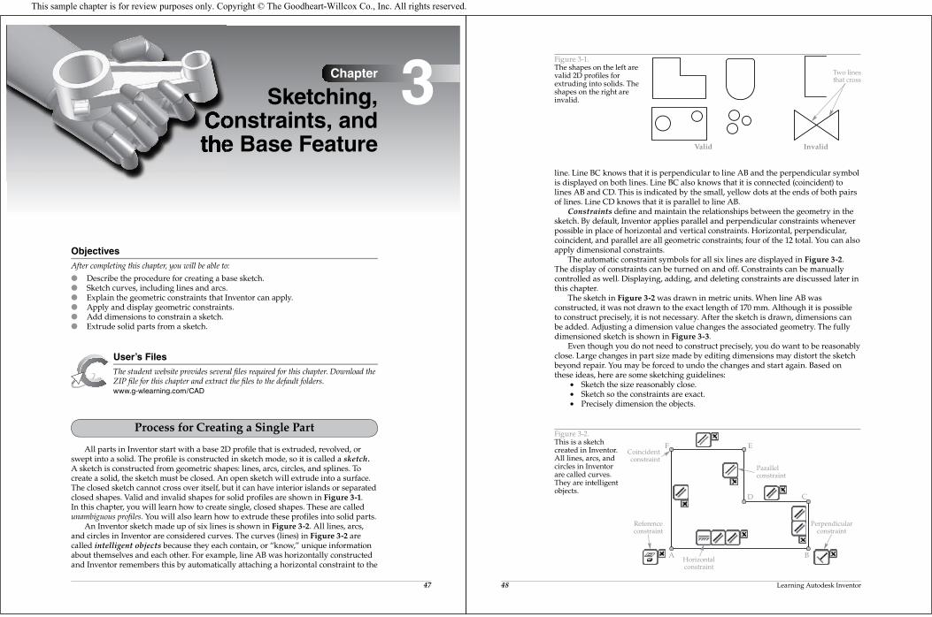
All parts in Inventor start with a base 2D profile that is extruded, revolved, orswept into a solid. The profile is constructed in sketch mode, so it is called a sketch.A sketch is constructed from geometric shapes: lines, arcs, circles, and splines. Tocreate a solid, the sketch must be closed. An open sketch will extrude into a surface.The closed sketch cannot cross over itself, but it can have interior islands or separatedclosed shapes. Valid and invalid shapes for solid profiles are shown in Figure 3-1.In this chapter, you will learn how to create single, closed shapes. These are calledunambiguous profiles. You will also learn how to extrude these profiles into solid parts.
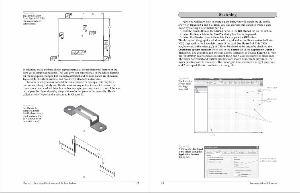
An Inventor sketch made up of six lines is shown in Figure 3-2. All lines, arcs,and circles in Inventor are considered curves. The curves (lines) in Figure 3-2 arecalled intelligent objects because they each contain, or “know,” unique informationabout themselves and each other. For example, line AB was horizontally constructedand Inventor remembers this by automatically attaching a horizontal constraint to the
3
48 Learning Autodesk Inventor
line. Line BC knows that it is perpendicular to line AB and the perpendicular symbolis displayed on both lines. Line BC also knows that it is connected (coincident) tolines AB and CD. This is indicated by the small, yellow dots at the ends of both pairsof lines. Line CD knows that it is parallel to line AB.
Constraints define and maintain the relationships between the geometry in thesketch. By default, Inventor applies parallel and perpendicular constraints wheneverpossible in place of horizontal and vertical constraints. Horizontal, perpendicular,coincident, and parallel are all geometric constraints; four of the 12 total. You can alsoapply dimensional constraints.
The automatic constraint symbols for all six lines are displayed in Figure 3-2.The display of constraints can be turned on and off. Constraints can be manuallycontrolled as well. Displaying, adding, and deleting constraints are discussed later inthis chapter.
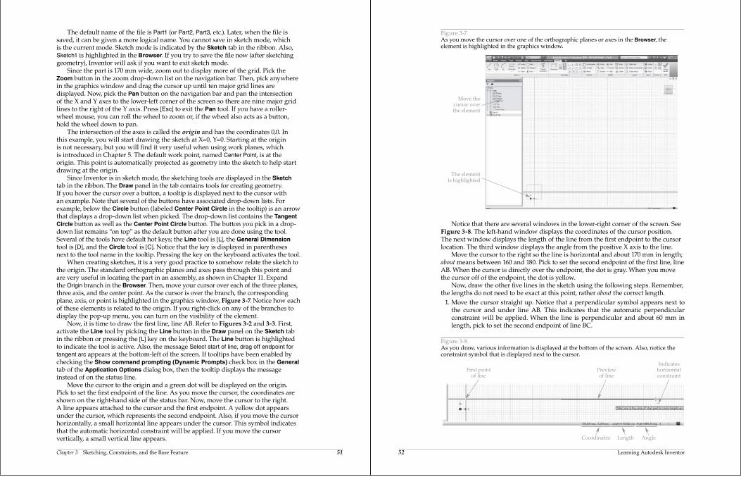
The sketch in Figure 3-2 was drawn in metric units. When line AB wasconstructed, it was not drawn to the exact length of 170 mm. Although it is possibleto construct precisely, it is not necessary. After the sketch is drawn, dimensions canbe added. Adjusting a dimension value changes the associated geometry. The fullydimensioned sketch is shown in Figure 3-3.
Even though you do not need to construct precisely, you do want to be reasonablyclose. Large changes in part size made by editing dimensions may distort the sketchbeyond repair. You may be forced to undo the changes and start again. Based onthese ideas, here are some sketching guidelines:
Sketch the size reasonably close. Sketch so the constraints are exact. Precisely dimension the objects.
Figure 3-1.The shapes on the left arevalid 2D profiles forextruding into solids. Theshapes on the right areinvalid.
Valid Invalid
Two linesthat cross
A B
CD
EF
Perpendicularconstraint
Horizontalconstraint
Coincidentconstraint
Parallelconstraint
Referenceconstraint
Figure 3-2.This is a sketchcreated in Inventor.All lines, arcs, andcircles in Inventorare called curves.They are intelligentobjects.
This sample chapter is for review purposes only. Copyright © The Goodheart-Willcox Co., Inc. All rights reserved.
Chapter 3 Sketching, Constraints, and the Base Feature 49
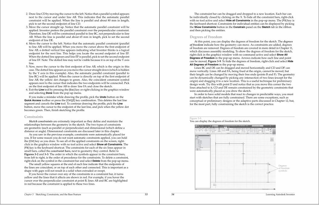
In addition, make the base sketch representative of the fundamental feature of thepart, yet as simple as possible. This will give you control of all of the added featuresfor making quick changes. For example, a bracket and its base sketch are shown inFigure 3-4. The fillets, cutouts, and holes were all added as features.
In some cases, you may not add the dimensions. For example, this may be apreliminary design study and the dimensions may not be known. Of course, thedimensions can be added later. In another example, you may want to control the sizeof the part (its dimensions) by the position of other parts in the assembly. This iscalled an adaptive part and is discussed in Chapter 12.
Figure 3-3.This is the sketchfrom Figure 3-2 fullydimensioned andconstrained.
A
B
Figure 3-4.A—This is thecompleted part.B—The base sketchused to create thepart (shown in anisometric view).
50 Learning Autodesk Inventor
Sketching
Now you will learn how to create a part. First, you will sketch the 2D profileshown in Figures 3-2 and 3-3. Then, you will extrude this sketch to create a part.Begin by starting a new metric part file: 1. Pick the New button on the Launch panel in the Get Started tab on the ribbon. 2. Select the Metric tab in the New File dialog box that is displayed. 3. Select the Standard (mm).ipt template file and pick the OK button.This brings up the graphics window with a grid and a coordinate system indicator(CSI) displayed in the lower-left corner of the grid. See Figure 3-5. This CSI isnot, however, at the origin (0,0). A CSI can be placed at the origin by checking theCoordinate system indicator check box in the Sketch tab of the Application Optionsdialog box. The grid lines and axes can also be turned on or off. See Figure 3-6. Withthe Presentation color scheme set current, the X and Y axes are shown as black lines.The major horizontal and vertical grid lines are shown as medium gray lines. Themajor grid lines are 20 mm apart. The minor grid lines are shown as light gray linesand 2 mm apart; this is considered a 2 mm grid.
CSI
Axes
Major gridlines
Minor gridlines
Figure 3-5.The Inventorscreen afterstarting anew part.
Check to displaya CSI at the origin
Figure 3-6.A CSI can be displayedat the origin using theApplication Optionsdialog box.
Chapter 3 Sketching, Constraints, and the Base Feature 51
The default name of the file is Part1 (or Part2, Part3, etc.). Later, when the file issaved, it can be given a more logical name. You cannot save in sketch mode, whichis the current mode. Sketch mode is indicated by the Sketch tab in the ribbon. Also,Sketch1 is highlighted in the Browser. If you try to save the file now (after sketchinggeometry), Inventor will ask if you want to exit sketch mode.
Since the part is 170 mm wide, zoom out to display more of the grid. Pick theZoom button in the zoom drop-down list on the navigation bar. Then, pick anywherein the graphics window and drag the cursor up until ten major grid lines aredisplayed. Now, pick the Pan button on the navigation bar and pan the intersectionof the X and Y axes to the lower-left corner of the screen so there are nine major gridlines to the right of the Y axis. Press [Esc] to exit the Pan tool. If you have a roller-wheel mouse, you can roll the wheel to zoom or, if the wheel also acts as a button,hold the wheel down to pan.
The intersection of the axes is called the origin and has the coordinates 0,0. Inthis example, you will start drawing the sketch at X=0, Y=0. Starting at the originis not necessary, but you will find it very useful when using work planes, whichis introduced in Chapter 5. The default work point, named Center Point, is at theorigin. This point is automatically projected as geometry into the sketch to help startdrawing at the origin.
Since Inventor is in sketch mode, the sketching tools are displayed in the Sketch tab in the ribbon. The Draw panel in the tab contains tools for creating geometry.If you hover the cursor over a button, a tooltip is displayed next to the cursor withan example. Note that several of the buttons have associated drop-down lists. Forexample, below the Circle button (labeled Center Point Circle in the tooltip) is an arrowthat displays a drop-down list when picked. The drop-down list contains the Tangent Circle button as well as the Center Point Circle button. The button you pick in a drop-down list remains “on top” as the default button after you are done using the tool.Several of the tools have default hot keys; the Line tool is [L], the General Dimensiontool is [D], and the Circle tool is [C]. Notice that the key is displayed in parenthesesnext to the tool name in the tooltip. Pressing the key on the keyboard activates the tool.
When creating sketches, it is a very good practice to somehow relate the sketch tothe origin. The standard orthographic planes and axes pass through this point andare very useful in locating the part in an assembly, as shown in Chapter 11. Expandthe Origin branch in the Browser. Then, move your cursor over each of the three planes,three axis, and the center point. As the cursor is over the branch, the correspondingplane, axis, or point is highlighted in the graphics window, Figure 3-7. Notice how eachof these elements is related to the origin. If you right-click on any of the branches todisplay the pop-up menu, you can turn on the visibility of the element.
Now, it is time to draw the first line, line AB. Refer to Figures 3-2 and 3-3. First,activate the Line tool by picking the Line button in the Draw panel on the Sketch tabin the ribbon or pressing the [L] key on the keyboard. The Line button is highlightedto indicate the tool is active. Also, the message Select start of line, drag off endpoint for tangent arc appears at the bottom-left of the screen. If tooltips have been enabled bychecking the Show command prompting (Dynamic Prompts) check box in the Generaltab of the Application Options dialog box, then the tooltip displays the messageinstead of on the status line.
Move the cursor to the origin and a green dot will be displayed on the origin.Pick to set the first endpoint of the line. As you move the cursor, the coordinates areshown on the right-hand side of the status bar. Now, move the cursor to the right.A line appears attached to the cursor and the first endpoint. A yellow dot appearsunder the cursor, which represents the second endpoint. Also, if you move the cursorhorizontally, a small horizontal line appears under the cursor. This symbol indicatesthat the automatic horizontal constraint will be applied. If you move the cursorvertically, a small vertical line appears.
52 Learning Autodesk Inventor
Notice that there are several windows in the lower-right corner of the screen. SeeFigure 3-8. The left-hand window displays the coordinates of the cursor position.The next window displays the length of the line from the first endpoint to the cursorlocation. The third window displays the angle from the positive X axis to the line.
Move the cursor to the right so the line is horizontal and about 170 mm in length;about means between 160 and 180. Pick to set the second endpoint of the first line, lineAB. When the cursor is directly over the endpoint, the dot is gray. When you movethe cursor off of the endpoint, the dot is yellow.
Now, draw the other five lines in the sketch using the following steps. Remember,the lengths do not need to be exact at this point, rather about the correct length.
1. Move the cursor straight up. Notice that a perpendicular symbol appears next tothe cursor and under line AB. This indicates that the automatic perpendicularconstraint will be applied. When the line is perpendicular and about 60 mm inlength, pick to set the second endpoint of line BC.
The elementis highlighted
Move thecursor overthe element
Figure 3-7.As you move the cursor over one of the orthographic planes or axes in the Browser, theelement is highlighted in the graphics window.
Coordinates AngleLength
Previewof line
Indicateshorizontalconstraint
First pointof line
Figure 3-8.As you draw, various information is displayed at the bottom of the screen. Also, notice theconstraint symbol that is displayed next to the cursor.
Chapter 3 Sketching, Constraints, and the Base Feature 53
2. Draw line CD by moving the cursor to the left. Notice that a parallel symbol appearsnext to the cursor and under line AB. This indicates that the automatic parallelconstraint will be applied. When the line is parallel and about 80 mm in length,pick to set the second endpoint of line CD.
3. Move the cursor straight up. Notice that the automatic parallel constraint will beapplied. Inventor prefers the parallel constraint over the perpendicular constraint.Therefore, line DE will be constrained parallel to line BC, not perpendicular to lineAB. When the line is parallel and about 65 mm in length, pick to set the secondendpoint of line DE.
4. Move the cursor to the left. Notice that the automatic parallel constraint (parallelto line AB) will be applied. When you move the cursor above the first endpoint ofline AB, a dotted vertical line appears indicating what Inventor thinks is a logicalendpoint for the next line. This helps you locate the second endpoint of line EF.When the dotted line appears and line EF is parallel, pick to set the second endpointof line EF. Note: The dotted line may not be visible because it is on top of the Y axisline.
5. Now, move the cursor to the first endpoint of line AB, which is the origin in thiscase. The dotted line appears as you move the cursor straight down (which is hiddenby the Y axis in this example). Also, the automatic parallel constraint (parallel toline BC) will be applied. When the cursor is directly on top of the first endpoint ofline AB, the yellow dot changes to green. Also, the coincident constraint symbolappears next to the cursor that indicates the two endpoints will be connected. Pickon the first endpoint of line AB to draw line FA and close the sketch.
6. Exit the Line tool by pressing the [Esc] key or right-clicking in the graphics windowand selecting Done from the pop-up menu.
If you make a mistake while drawing the profile, pick the Undo button on theQuick Access toolbar or press the [Ctrl][Z] key combination. This deletes the last linesegment and cancels the Line tool. To continue drawing the profile, pick the Linebutton, move the cursor to the endpoint of the last line, and pick when the yellow dotbecomes green. Then, finish sketching the profile.
ConstraintsSketch constraints are extremely important as they define and maintain the
relationships between the geometry in the sketch. The two types of constraintsare geometric (such as parallel or perpendicular) and dimensional (which define adistance or angle). Dimensional constraints are discussed later in this chapter.
As you saw in the previous example, constraints were automatically placed foryou. If for some reason you do not want automatic constraints applied, you can holdthe [Ctrl] key as you draw. To see all of the applied constraints on the screen, right-click in the graphics window with no tool active and select Show all Constraints. The[F8] key is the keyboard shortcut. The constraints for each of the six lines appear insmall bars, called the constraint bars, next to geometry they control. Refer toFigures 3-2 and 3-3. The order in which the symbols appear in the constraint bars,from left to right, is the order of precedence for the constraints. To delete a constraint,right-click on the symbol in the constraint bar and select Delete from the pop-up menu.
The small yellow squares at the end of each line indicate that the endpoints ofthe lines are coincident, or on top of each other and connected. This is important as ashape with gaps will not result in a solid when extruded or swept.
If you hover the cursor over any of the constraints in a constraint bar, it turnsyellow and the lines that it affects are shown in red. For example, if you hover thecursor over the perpendicular constraint at point B, lines AB and BC are highlightedin red because the constraint is applied to these two lines.
54 Learning Autodesk Inventor
The constraint bar can be dragged and dropped to a new location. Each bar canbe individually closed by clicking on the X. To hide all the constraint bars, right-clickwith no tool active and select Hide all Constraints in the pop-up menu. The [F9] key isthe keyboard shortcut. Constraints for individual entities can be displayed by pickingthe Show Constraints button in the Constrain panel on the Sketch tab in the ribbonand then picking the entities.
Degrees of FreedomAt this point, you can display the degrees of freedom for the sketch. The degrees
of freedom indicate how the geometry can move. As constraints are added, degreesof freedom are removed. Degrees of freedom are covered in more detail in Chapter 11,which discusses assembly modeling. To show the degrees of freedom for the sketch,right-click in the graphics window with no command active and select Show All Degrees of Freedom in the pop-up menu. Arrows indicate how each line and pointcan be moved, Figure 3-9. To hide the degrees of freedom, right-click and select Hide All Degrees of Freedom in the pop-up menu.
Lines BC and DE can be dragged and moved horizontally and CD and DF canmove vertically. Lines AB and FA, being fixed at the origin, cannot be moved, buttheir length can be changed by moving their free ends (points B and F). The geometrycan be dynamically changed by picking any intersection of two lines (except for theorigin) and dragging it to a new location. This is a useful technique for preliminarydesign work. Try this with point D and notice that as you move this corner the twolines attached to it, CD and DE remain constrained by the geometric constraints thatwere automatically placed as you drew the sketch.
In order to have solid models that react to changes in predictable ways, you muststart with sketches that are fully constrained. There are some exceptions, such asconceptual or preliminary designs or the adaptive parts discussed in Chapter 12, but,for the most part, fully constraining the sketch is the correct practice.
Degreesof freedomsymbols
Figure 3-9.You can display the degrees of freedom for the sketch.
Chapter 3 Sketching, Constraints, and the Base Feature 55
DimensionsGeometric constraints alone will not fully constrain a sketch. Apply as many as
possible and then add dimensions until the sketch is fully constrained. The numberof dimensions required is displayed at the right-hand side of the status bar. In thisexample, Inventor reports that four dimensions are required.
You have two choices for applying the dimensions needed to accurately size thepart. You can apply automatic dimensions, in which case Inventor decides where thedimensions should be placed. Alternately, you can manually apply and place eachdimension.
To manually apply a dimension, pick the Dimension button (labeled General Dimension in the tooltip) on the Constrain panel in the Sketch tab of the ribbon orpress the [D] key. Then, pick the geometry to which you want the dimension applied.Finally, drag the dimension to the desired location. To cancel the Dimension tool,press the [Esc] key.
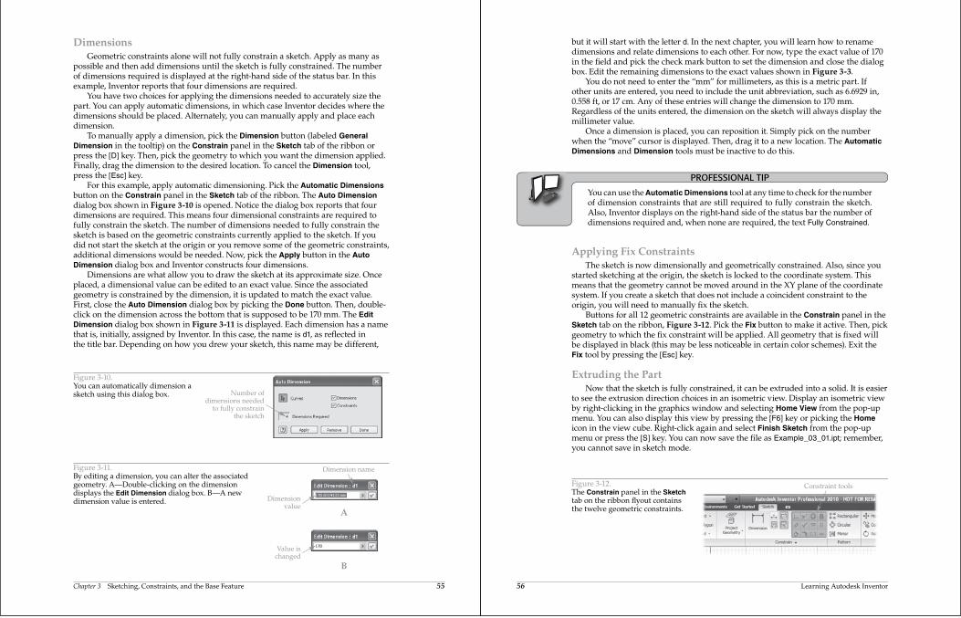
For this example, apply automatic dimensioning. Pick the Automatic Dimensionsbutton on the Constrain panel in the Sketch tab of the ribbon. The Auto Dimensiondialog box shown in Figure 3-10 is opened. Notice the dialog box reports that fourdimensions are required. This means four dimensional constraints are required tofully constrain the sketch. The number of dimensions needed to fully constrain thesketch is based on the geometric constraints currently applied to the sketch. If youdid not start the sketch at the origin or you remove some of the geometric constraints,additional dimensions would be needed. Now, pick the Apply button in the Auto Dimension dialog box and Inventor constructs four dimensions.
Dimensions are what allow you to draw the sketch at its approximate size. Onceplaced, a dimensional value can be edited to an exact value. Since the associatedgeometry is constrained by the dimension, it is updated to match the exact value.First, close the Auto Dimension dialog box by picking the Done button. Then, double-click on the dimension across the bottom that is supposed to be 170 mm. The Edit Dimension dialog box shown in Figure 3-11 is displayed. Each dimension has a namethat is, initially, assigned by Inventor. In this case, the name is d1, as reflected inthe title bar. Depending on how you drew your sketch, this name may be different,
Number ofdimensions needed
to fully constrainthe sketch
Figure 3-10.You can automatically dimension asketch using this dialog box.
Dimensionvalue
Value ischanged
Dimension name
A
B
Figure 3-11.By editing a dimension, you can alter the associatedgeometry. A—Double-clicking on the dimensiondisplays the Edit Dimension dialog box. B—A newdimension value is entered.
56 Learning Autodesk Inventor
but it will start with the letter d. In the next chapter, you will learn how to renamedimensions and relate dimensions to each other. For now, type the exact value of 170in the field and pick the check mark button to set the dimension and close the dialogbox. Edit the remaining dimensions to the exact values shown in Figure 3-3.
You do not need to enter the “mm” for millimeters, as this is a metric part. Ifother units are entered, you need to include the unit abbreviation, such as 6.6929 in,0.558 ft, or 17 cm. Any of these entries will change the dimension to 170 mm.Regardless of the units entered, the dimension on the sketch will always display themillimeter value.
Once a dimension is placed, you can reposition it. Simply pick on the numberwhen the “move” cursor is displayed. Then, drag it to a new location. The Automatic Dimensions and Dimension tools must be inactive to do this.
PROFESSIONAL TIP
You can use the Automatic Dimensions tool at any time to check for the numberof dimension constraints that are still required to fully constrain the sketch.Also, Inventor displays on the right-hand side of the status bar the number ofdimensions required and, when none are required, the text Fully Constrained.
Applying Fix ConstraintsThe sketch is now dimensionally and geometrically constrained. Also, since you
started sketching at the origin, the sketch is locked to the coordinate system. Thismeans that the geometry cannot be moved around in the XY plane of the coordinatesystem. If you create a sketch that does not include a coincident constraint to theorigin, you will need to manually fix the sketch.
Buttons for all 12 geometric constraints are available in the Constrain panel in theSketch tab on the ribbon, Figure 3-12. Pick the Fix button to make it active. Then, pickgeometry to which the fix constraint will be applied. All geometry that is fixed willbe displayed in black (this may be less noticeable in certain color schemes). Exit theFix tool by pressing the [Esc] key.
Extruding the PartNow that the sketch is fully constrained, it can be extruded into a solid. It is easier
to see the extrusion direction choices in an isometric view. Display an isometric viewby right-clicking in the graphics window and selecting Home View from the pop-upmenu. You can also display this view by pressing the [F6] key or picking the Homeicon in the view cube. Right-click again and select Finish Sketch from the pop-upmenu or press the [S] key. You can now save the file as Example_03_01.ipt; remember,you cannot save in sketch mode.
Constraint toolsFigure 3-12.The Constrain panel in the Sketchtab on the ribbon flyout containsthe twelve geometric constraints.
Chapter 3 Sketching, Constraints, and the Base Feature 57
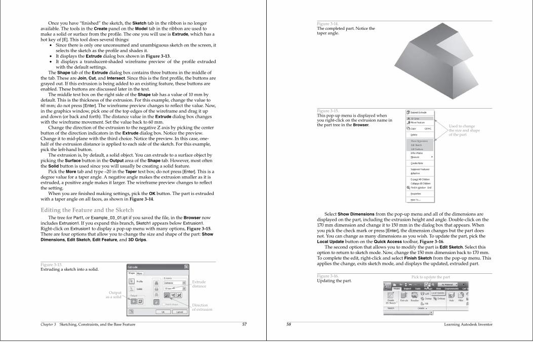
Once you have “finished” the sketch, the Sketch tab in the ribbon is no longeravailable. The tools in the Create panel on the Model tab in the ribbon are used tomake a solid or surface from the profile. The one you will use is Extrude, which has ahot key of [E]. This tool does several things:
Since there is only one unconsumed and unambiguous sketch on the screen, itselects the sketch as the profile and shades it.
It displays the Extrude dialog box shown in Figure 3-13. It displays a translucent-shaded wireframe preview of the profile extruded
with the default settings.The Shape tab of the Extrude dialog box contains three buttons in the middle of
the tab. These are Join, Cut, and Intersect. Since this is the first profile, the buttons aregrayed out. If this extrusion is being added to an existing feature, these buttons areenabled. These buttons are discussed later in the text.
The middle text box on the right side of the Shape tab has a value of 10 mm bydefault. This is the thickness of the extrusion. For this example, change the value to60 mm; do not press [Enter]. The wireframe preview changes to reflect the value. Now,in the graphics window, pick one of the top edges of the wireframe and drag it upand down (or back and forth). The distance value in the Extrude dialog box changeswith the wireframe movement. Set the value back to 60 mm.
Change the direction of the extrusion to the negative Z axis by picking the centerbutton of the direction indicators in the Extrude dialog box. Notice the preview.Change it to mid-plane with the third choice. Notice the preview. In this case, one-half of the extrusion distance is applied to each side of the sketch. For this example,pick the left-hand button.
The extrusion is, by default, a solid object. You can extrude to a surface object bypicking the Surface button in the Output area of the Shape tab. However, most oftenthe Solid button is used since you will usually be creating a solid feature.
Pick the More tab and type –20 in the Taper text box; do not press [Enter]. This is adegree value for a taper angle. A negative angle makes the extrusion smaller as it isextruded, a positive angle makes it larger. The wireframe preview changes to reflectthe setting.
When you are finished making settings, pick the OK button. The part is extrudedwith a taper angle on all faces, as shown in Figure 3-14.
Editing the Feature and the SketchThe tree for Part1, or Example_03_01.ipt if you saved the file, in the Browser now
includes Extrusion1. If you expand this branch, Sketch1 appears below Extrusion1.Right-click on Extrusion1 to display a pop-up menu with many options, Figure 3-15.There are four options that allow you to change the size and shape of the part: Show Dimensions, Edit Sketch, Edit Feature, and 3D Grips.
Directionof extrusion
Extrudedistance
Outputas a solid
Figure 3-13.Extruding a sketch into a solid.
58 Learning Autodesk Inventor
Select Show Dimensions from the pop-up menu and all of the dimensions aredisplayed on the part, including the extrusion height and angle. Double-click on the170 mm dimension and change it to 150 mm in the dialog box that appears. Whenyou pick the check mark or press [Enter], the dimension changes but the part doesnot. You can change as many dimensions as you wish. To update the part, pick theLocal Update button on the Quick Access toolbar, Figure 3-16.
The second option that allows you to modify the part is Edit Sketch. Select thisoption to return to sketch mode. Now, change the 150 mm dimension back to 170 mm.To complete the edit, right-click and select Finish Sketch from the pop-up menu. Thisapplies the change, exits sketch mode, and displays the updated, extruded part.
Figure 3-14.The completed part. Notice thetaper angle.
Figure 3-15.This pop-up menu is displayed whenyou right-click on the extrusion name inthe part tree in the Browser. Used to change
the size and shapeof the part
Pick to update the partFigure 3-16.Updating the part.
Chapter 3 Sketching, Constraints, and the Base Feature 59
The third option that allows you to modify the part is Edit Feature. This optiondisplays the Extrude dialog box in which changes can be made to the extrudeddistance, direction, taper angle, and sketch dimensions. Change the taper to 0 in theMore tab. Then, pick the OK button and the part is updated.
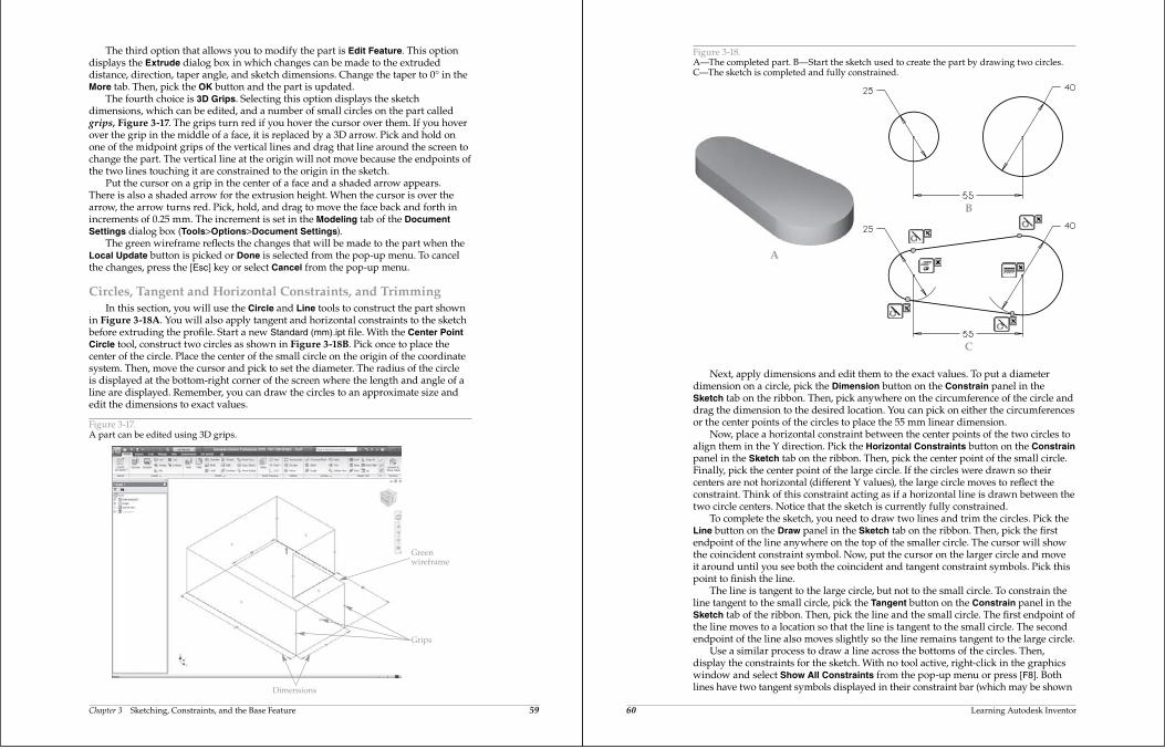
The fourth choice is 3D Grips. Selecting this option displays the sketchdimensions, which can be edited, and a number of small circles on the part calledgrips, Figure 3-17. The grips turn red if you hover the cursor over them. If you hoverover the grip in the middle of a face, it is replaced by a 3D arrow. Pick and hold onone of the midpoint grips of the vertical lines and drag that line around the screen tochange the part. The vertical line at the origin will not move because the endpoints ofthe two lines touching it are constrained to the origin in the sketch.
Put the cursor on a grip in the center of a face and a shaded arrow appears.There is also a shaded arrow for the extrusion height. When the cursor is over thearrow, the arrow turns red. Pick, hold, and drag to move the face back and forth inincrements of 0.25 mm. The increment is set in the Modeling tab of the Document Settings dialog box (Tools>Options>Document Settings).
The green wireframe reflects the changes that will be made to the part when theLocal Update button is picked or Done is selected from the pop-up menu. To cancelthe changes, press the [Esc] key or select Cancel from the pop-up menu.
Circles, Tangent and Horizontal Constraints, and TrimmingIn this section, you will use the Circle and Line tools to construct the part shown
in Figure 3-18A. You will also apply tangent and horizontal constraints to the sketchbefore extruding the profile. Start a new Standard (mm).ipt file. With the Center Point Circle tool, construct two circles as shown in Figure 3-18B. Pick once to place thecenter of the circle. Place the center of the small circle on the origin of the coordinatesystem. Then, move the cursor and pick to set the diameter. The radius of the circleis displayed at the bottom-right corner of the screen where the length and angle of aline are displayed. Remember, you can draw the circles to an approximate size andedit the dimensions to exact values.
Greenwireframe
Grips
Dimensions
Figure 3-17.A part can be edited using 3D grips.
60 Learning Autodesk Inventor
Next, apply dimensions and edit them to the exact values. To put a diameterdimension on a circle, pick the Dimension button on the Constrain panel in theSketch tab on the ribbon. Then, pick anywhere on the circumference of the circle anddrag the dimension to the desired location. You can pick on either the circumferencesor the center points of the circles to place the 55 mm linear dimension.
Now, place a horizontal constraint between the center points of the two circles toalign them in the Y direction. Pick the Horizontal Constraints button on the Constrainpanel in the Sketch tab on the ribbon. Then, pick the center point of the small circle.Finally, pick the center point of the large circle. If the circles were drawn so theircenters are not horizontal (different Y values), the large circle moves to reflect theconstraint. Think of this constraint acting as if a horizontal line is drawn between thetwo circle centers. Notice that the sketch is currently fully constrained.
To complete the sketch, you need to draw two lines and trim the circles. Pick theLine button on the Draw panel in the Sketch tab on the ribbon. Then, pick the firstendpoint of the line anywhere on the top of the smaller circle. The cursor will showthe coincident constraint symbol. Now, put the cursor on the larger circle and moveit around until you see both the coincident and tangent constraint symbols. Pick thispoint to finish the line.
The line is tangent to the large circle, but not to the small circle. To constrain theline tangent to the small circle, pick the Tangent button on the Constrain panel in theSketch tab of the ribbon. Then, pick the line and the small circle. The first endpoint ofthe line moves to a location so that the line is tangent to the small circle. The secondendpoint of the line also moves slightly so the line remains tangent to the large circle.
Use a similar process to draw a line across the bottoms of the circles. Then,display the constraints for the sketch. With no tool active, right-click in the graphicswindow and select Show All Constraints from the pop-up menu or press [F8]. Bothlines have two tangent symbols displayed in their constraint bar (which may be shown
Figure 3-18.A—The completed part. B—Start the sketch used to create the part by drawing two circles.C—The sketch is completed and fully constrained.
A
B
C
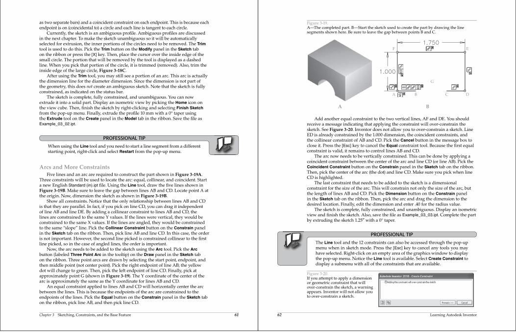
Chapter 3 Sketching, Constraints, and the Base Feature 61
as two separate bars) and a coincident constraint on each endpoint. This is because eachendpoint is on (coincidental to) a circle and each line is tangent to each circle.
Currently, the sketch is an ambiguous profile. Ambiguous profiles are discussedin the next chapter. To make the sketch unambiguous so it will be automaticallyselected for extrusion, the inner portions of the circles need to be removed. The Trimtool is used to do this. Pick the Trim button on the Modify panel in the Sketch tabon the ribbon or press the [X] key. Then, place the cursor over the inside edge of thesmall circle. The portion that will be removed by the tool is displayed as a dashedline. When you pick that portion of the circle, it is trimmed (removed). Also, trim theinside edge of the large circle, Figure 3-18C.
After using the Trim tool, you may still see a portion of an arc. This arc is actuallythe dimension line for the diameter dimension. Since the dimension is not part ofthe geometry, this does not create an ambiguous sketch. Note that the sketch is fullyconstrained, as indicated on the status bar.
The sketch is complete, fully constrained, and unambiguous. You can nowextrude it into a solid part. Display an isometric view by picking the Home icon onthe view cube. Then, finish the sketch by right-clicking and selecting Finish Sketchfrom the pop-up menu. Finally, extrude the profile 10 mm with a 0 taper usingthe Extrude tool on the Create panel in the Model tab in the ribbon. Save the file asExample_03_02.ipt.
PROFESSIONAL TIP
When using the Line tool and you need to start a line segment from a differentstarting point, right-click and select Restart from the pop-up menu.
Arcs and More ConstraintsFive lines and an arc are required to construct the part shown in Figure 3-19A.
Three constraints will be used to locate the arc: equal, collinear, and coincident. Starta new English Standard (in).ipt file. Using the Line tool, draw the five lines shown inFigure 3-19B. Make sure to leave the gap between lines AB and CD. Locate point A atthe origin. Now, dimension the sketch as shown in Figure 3-19B.
Show all constraints. Notice that the only relationship between lines AB and CDis that they are parallel. In fact, if you pick on line CD, you can drag it independentof line AB and line DE. By adding a collinear constraint to lines AB and CD, thelines are constrained to the same Y values. If the lines were vertical, they would beconstrained to the same X values. If the lines are angled, they would be constrainedto the same “slope” line. Pick the Collinear Constraint button on the Constrain panelin the Sketch tab on the ribbon. Then, pick line AB and line CD. In this case, the orderis not important. However, the second line picked is constrained collinear to the firstline picked, so in the case of angled lines, the order is important.
Now, the arc needs to be added to the sketch using the Arc tool. Pick the Arcbutton (labeled Three Point Arc in the tooltip) on the Draw panel in the Sketch tabon the ribbon. Three point arcs are drawn by selecting the start point, endpoint, andthen middle point (not center point). Pick the right endpoint of line AB; the yellowdot will change to green. Then, pick the left endpoint of line CD. Finally, pick atapproximately point G (shown in Figure 3-19). The Y coordinate of the center of thearc is approximately the same as the Y coordinate for lines AB and CD.
An equal constraint applied to lines AB and CD will horizontally center the arcbetween the lines. This is because the endpoints of the arc are constrained to theendpoints of the lines. Pick the Equal button on the Constrain panel in the Sketch tabon the ribbon, pick line AB, and then pick line CD.
62 Learning Autodesk Inventor
Add another equal constraint to the two vertical lines, AF and DE. You shouldreceive a message indicating that applying the constraint will over-constrain thesketch. See Figure 3-20. Inventor does not allow you to over-constrain a sketch. LineED is already constrained by the 1.000 dimension, the coincident constraints, andthe collinear constraint of AB and CD. Pick the Cancel button in the message box toclose it. Press the [Esc] key to cancel the Equal constraint tool. Because the first equalconstraint is valid, it remains to control lines AB and CD.
The arc now needs to be vertically constrained. This can be done by applying acoincident constraint between the center of the arc and line CD (or line AB). Pick theCoincident Constraint button on the Constrain panel in the Sketch tab on the ribbon.Then, pick the center of the arc (the dot) and line CD. Make sure you pick when lineCD is highlighted.
The last constraint that needs to be added to the sketch is a dimensionalconstraint for the size of the arc. This will constrain not only the size of the arc, butthe length of lines AB and CD. Pick the Dimension button on the Constrain panelin the Sketch tab on the ribbon. Then, pick the arc and drag the dimension to thedesired location. Finally, edit the dimension and enter .40 for the radius value.
The sketch is complete, fully constrained, and unambiguous. Display an isometricview and finish the sketch. Also, save the file as Example_03_03.ipt. Complete the partby extruding the sketch 1.25 with a 0 taper.
PROFESSIONAL TIP
The Line tool and the 12 constraints can also be accessed through the pop-upmenu when in sketch mode. Press the [Esc] key to cancel any tools you mayhave selected. Right-click on an empty area of the graphics window to displaythe pop-up menu. Notice the Line tool is available. Select Create Constraint todisplay a submenu with all of the constraints that are available.
A B
A B C D
F E
G
Figure 3-19.A—The completed part. B—Start the sketch used to create the part by drawing the linesegments shown here. Be sure to leave the gap between points B and C.
Figure 3-20.If you attempt to apply a dimensionor geometric constraint that willover-constrain the sketch, a warningappears. Inventor will not allow youto over-constrain a sketch.
Chapter 3 Sketching, Constraints, and the Base Feature 63
PRACTICE 3-1Complete the practice problem on the student website.www.g-wlearning.com/CAD
Drawing an Arc from within the Line ToolTangent and perpendicular arcs can also be constructed from within the Line
tool. For example, the sketch shown in Figure 3-21 can be constructed, not includingdimensions, using only one session of the Line tool. This is a little tricky, but, oncemastered, you will find it very useful.
Start a new metric Standard (mm).ipt file. Draw a line from point A (at the origin)to point B about 170 mm long. Now, move the cursor over point B and let it “hover.”The yellow dot will change to gray. Pick and drag the cursor to the right and up, as ifyou were sketching an arc. Release the mouse button when the radius is about 40, asshown on the right-hand side of the status bar. The arc segment is constructed. Then,draw line CD normally. Finally, use the same “drag off” method to draw the secondarc from point D to point A.
Show all constraints. Make sure both arcs are tangent to both lines. If not, add thenecessary tangent constraint. Now, if you were going to finish the part, you can adddimensions and adjust their values. Then, finish the sketch and extrude the part.
PRACTICE 3-2Complete the practice problem on the student website.www.g-wlearning.com/CAD
Things That Can Go Wrong with Sketches
There are several mistakes you can make in the construction of sketches that willgenerate errors when you attempt to create a solid feature. The two most commonerrors are having gaps at corners and having overlapping lines. For example, openthe Example_03_04.ipt file. There is a very small gap between the two lines in theupper-right corner, as shown in Figure 3-22.
Pick the Extrude button in the Create panel in the Model tab on the ribbon. In theExtrude dialog box, notice that the Surface button is on in the Output area. Because ofthe gap, Inventor assumes this sketch is to be extruded into a surface. However, youwant this to be a solid, not a surface, so pick the Solid button. A new button—witha red cross—appears below the Output area. See Figure 3-23. This button indicatesa solid cannot be created because a problem exists. If you hover the cursor over thebutton, the tooltip is Examine Profile Problems.
A
D
B
C
Figure 3-21.All curves in this sketchcan be drawn in a singlesession of the Line tool.
64 Learning Autodesk Inventor
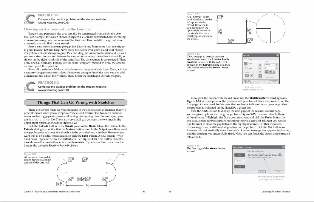
Figure 3-22.At a “normal” zoomlevel, the sketch on theleft appears to beclosed. However, ifyou zoom in on theupper-right corner ofthe sketch, there is asmall gap, as shown inthe detail.
Pick to open theSketch Doctor wizard
Figure 3-23.If you attempt to extrude an opensketch into a solid, the Examine Profile Problems button (with the red cross)appears in the Extrude dialog box. Pickthis button to open the Sketch Doctorwizard.
Now, pick the button with the red cross and the Sketch Doctor wizard appears,Figure 3-24. A description of the problem and possible solutions are provided on thefirst page of the wizard. In this case, the problem is indicated as an open loop. Also,the problem is indicated on the sketch by a green dot.
Pick the Next> button to display the next page of the wizard. On this page,you are given options for fixing the problem, Figure 3-25. Inventor refers to theseas “treatments.” Highlight the Close Loop treatment and pick the Finish button. Inthis case, a message box appears indicating there is a gap and asking if you wouldlike Inventor to close the gap between the highlighted lines. In other instances,this message may be different, depending on the problem. Pick the Yes button andInventor will automatically close the sketch. Another message box appears indicatingthat the problem was successfully fixed. Now, you can finish the sketch and extrude itinto a solid.
Description of the problemand suggested solutions
Figure 3-24.The first page of the Sketch Doctorwizard.
Chapter 3 Sketching, Constraints, and the Base Feature 65
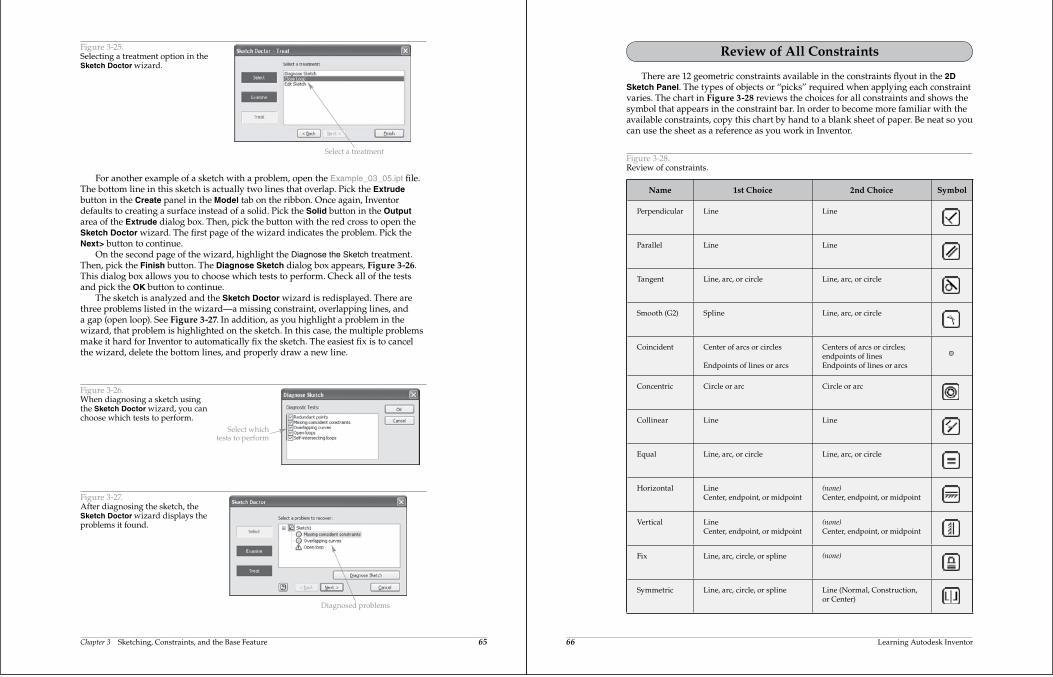
For another example of a sketch with a problem, open the Example_03_05.ipt file.The bottom line in this sketch is actually two lines that overlap. Pick the Extrudebutton in the Create panel in the Model tab on the ribbon. Once again, Inventordefaults to creating a surface instead of a solid. Pick the Solid button in the Outputarea of the Extrude dialog box. Then, pick the button with the red cross to open theSketch Doctor wizard. The first page of the wizard indicates the problem. Pick theNext> button to continue.
On the second page of the wizard, highlight the Diagnose the Sketch treatment.Then, pick the Finish button. The Diagnose Sketch dialog box appears, Figure 3-26.This dialog box allows you to choose which tests to perform. Check all of the testsand pick the OK button to continue.
The sketch is analyzed and the Sketch Doctor wizard is redisplayed. There arethree problems listed in the wizard—a missing constraint, overlapping lines, anda gap (open loop). See Figure 3-27. In addition, as you highlight a problem in thewizard, that problem is highlighted on the sketch. In this case, the multiple problemsmake it hard for Inventor to automatically fix the sketch. The easiest fix is to cancelthe wizard, delete the bottom lines, and properly draw a new line.
Select a treatment
Figure 3-25.Selecting a treatment option in theSketch Doctor wizard.
Select whichtests to perform
Figure 3-26.When diagnosing a sketch usingthe Sketch Doctor wizard, you canchoose which tests to perform.
Diagnosed problems
Figure 3-27.After diagnosing the sketch, theSketch Doctor wizard displays theproblems it found.
66 Learning Autodesk Inventor
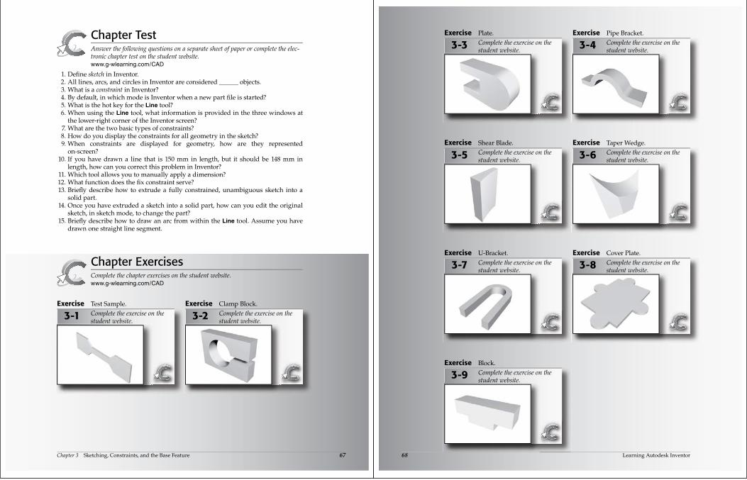
Name 1st Choice 2nd Choice Symbol
Perpendicular Line Line
Parallel Line Line
Tangent Line, arc, or circle Line, arc, or circle
Smooth (G2) Spline Line, arc, or circle
Coincident Center of arcs or circles
Endpoints of lines or arcs
Centers of arcs or circles;endpoints of linesEndpoints of lines or arcs
Concentric Circle or arc Circle or arc
Collinear Line Line
Equal Line, arc, or circle Line, arc, or circle
Horizontal LineCenter, endpoint, or midpoint
(none)Center, endpoint, or midpoint
Vertical LineCenter, endpoint, or midpoint
(none)Center, endpoint, or midpoint
Fix Line, arc, circle, or spline (none)
Symmetric Line, arc, circle, or spline Line (Normal, Construction,or Center)
Review of All Constraints
There are 12 geometric constraints available in the constraints flyout in the 2D Sketch Panel. The types of objects or “picks” required when applying each constraintvaries. The chart in Figure 3-28 reviews the choices for all constraints and shows thesymbol that appears in the constraint bar. In order to become more familiar with theavailable constraints, copy this chart by hand to a blank sheet of paper. Be neat so youcan use the sheet as a reference as you work in Inventor.
Figure 3-28.Review of constraints.
Chapter 3 Sketching, Constraints, and the Base Feature 67
Chapter TestAnswer the following questions on a separate sheet of paper or complete the elec-tronic chapter test on the student website.www.g-wlearning.com/CAD
1. Define sketch in Inventor. 2. All lines, arcs, and circles in Inventor are considered ______ objects. 3. What is a constraint in Inventor? 4. By default, in which mode is Inventor when a new part file is started? 5. What is the hot key for the Line tool? 6. When using the Line tool, what information is provided in the three windows at
the lower-right corner of the Inventor screen? 7. What are the two basic types of constraints? 8. How do you display the constraints for all geometry in the sketch? 9. When constraints are displayed for geometry, how are they represented
on-screen? 10. If you have drawn a line that is 150 mm in length, but it should be 148 mm in
length, how can you correct this problem in Inventor? 11. Which tool allows you to manually apply a dimension? 12. What function does the fix constraint serve? 13. Briefly describe how to extrude a fully constrained, unambiguous sketch into a
solid part. 14. Once you have extruded a sketch into a solid part, how can you edit the original
sketch, in sketch mode, to change the part? 15. Briefly describe how to draw an arc from within the Line tool. Assume you have
drawn one straight line segment.
Chapter ExercisesComplete the chapter exercises on the student website.www.g-wlearning.com/CAD
3-1Exercise Test Sample.
Complete the exercise on the student website.
3-2Exercise Clamp Block.
Complete the exercise on the student website.
68 Learning Autodesk Inventor
3-3 3-4
3-5 3-6
3-7 3-8
3-9
Exercise Plate.
Complete the exercise on the student website.
Exercise Pipe Bracket.
Complete the exercise on the student website.
Exercise Shear Blade.
Complete the exercise on the student website.
Exercise Taper Wedge.
Complete the exercise on the student website.
Exercise U-Bracket.
Complete the exercise on the student website.
Exercise Cover Plate.
Complete the exercise on the student website.
Exercise Block.
Complete the exercise on the student website.