the assessment of changes in the microstructure of a gas turbine blade...
TRANSCRIPT

Journal of KONES Powertrain and Transport, Vol. 19, No. 2 2012
THE ASSESSMENT OF CHANGES IN THE MICROSTRUCTURE OF A GAS TURBINE BLADE WITH A NON-DESTRUCTIVE
THERMOGRAPHIC METHOD
Artur Ku aszka, Józef B achnio
Air Force Institute of Technology Ksi cia Boles awa Street 6, 01-494 Warsaw Poland
tel.: 022 6851-213, fax. 0-22 6851 041 e-mail: [email protected], [email protected]
Dariusz Zasada, Pawe Jó wik
Military University of Technology
Kaliskiego Street 2, 00-908 Warszawa, Poland tel.: +48 22 683-93-49, +48 22 683 71-35
e-mail: [email protected], [email protected]
Abstract
Diagnostic methods applied nowadays to examine condition of a gas turbine blade have been discussed in the Introduction section. What follows in the body of the paper is presentation of findings on the assessment of changes in the microstructure of a gas turbine blade with a non-destructive thermographic method. A laboratory experiment performed on new turbine rotor blades made of the EI 867WD alloy has been described. The experiment consisted in holding the blades at different temperatures in the exhaust-gas environment produced by an aircraft engine supplied with jet fuel. The pulsed thermography method has been used to determine and analyse the temperature distribution upon the examined area while cooling-down after the earlier uniform warming it up with a heat pulse. Diffusion and effusion of heat in the alloy have been examined. Both phenomena are determined with thermal properties and other physical properties such as size, shape, weight, structure, chemical composition, thickness of the protective coating of the blade. Examination of the microstructure of the blade material has shown the increased thickness of the coating, grain size, and in particular disadvantageous modification in the strengthening ’ phase against temperature. Finding the relationship between parameters of thermal responses of blade materials to heat pulse against the average size of precipitates of the ’ phase and thickness of the aluminium protective coating enables inferences on changes in the blade material’s condition. With this relationship as the basis and knowing permissible changes to the microstructure one can determine the ‘fit-for-use’ and ‘unfit-for-use’ (i.e. serviceable and unserviceable) conditions of the blades. Assuming the material criterion, i.e. some disadvantageous change in the morphology of precipitates of the ’ phase in the EI 867WD alloy under examination, the ‘fit-for-use’ (serviceability) thresholds for blades affected with different temperatures have been defined.
Keywords: gas turbine, blade, pulsed thermography diagnosing, health/maintenance status 1. Introduction
Gas turbines are key structural components of power engineering units or engines widely
applied to power engineering, traction, marine or avionic solutions. They are rotary fluid-flow machines that convert enthalpy of a working agent into mechanical work. Power of the turbine is the crucial factor that defines performances of the driving unit, i.e. any improvement of the turbine efficiency entails increase of the turbine power and savings on unit consumption of fuel and vice versa. At the same time, the turbine that is subjected to huge thermal and mechanical impacts (in particular bladed rotary rims) is vital for reliability and lifetime of structural subassemblies where the turbine is embedded.
ISSN: 1231-4005 e-ISSN: 2354-0133 DOI: 10.5604/12314005.1137935
A. Ku aszka, J. B achnio, D. Zasada, P. Jó wik
In consequence, turbines benefit from continuous technical progress both in terms of new design solutions and composition of materials the aircraft engines are made of, which leads to enhanced efficiency and better performances and, subsequently, improved cost-effectiveness and optimization of their weight and overall dimensions.
Turbine blades are the components that are mostly exposed to failures, whilst technical condition of them is crucial for reliability and operation lifetime of the turbine as a whole and the subassembly, where the turbine is incorporated [2, 7, 8]. The major reasons for failures of gas turbine blades include thermal fatigue and overheating of the material [8, 12, 15]. It is caused by unfavourable operating conditions associated with incorrect settings of engine parameters, fuel quality or manufacturing deficiencies, e.g. application of protective coatings with insufficient strength or technological errors in application of such coatings onto parent material of blades.
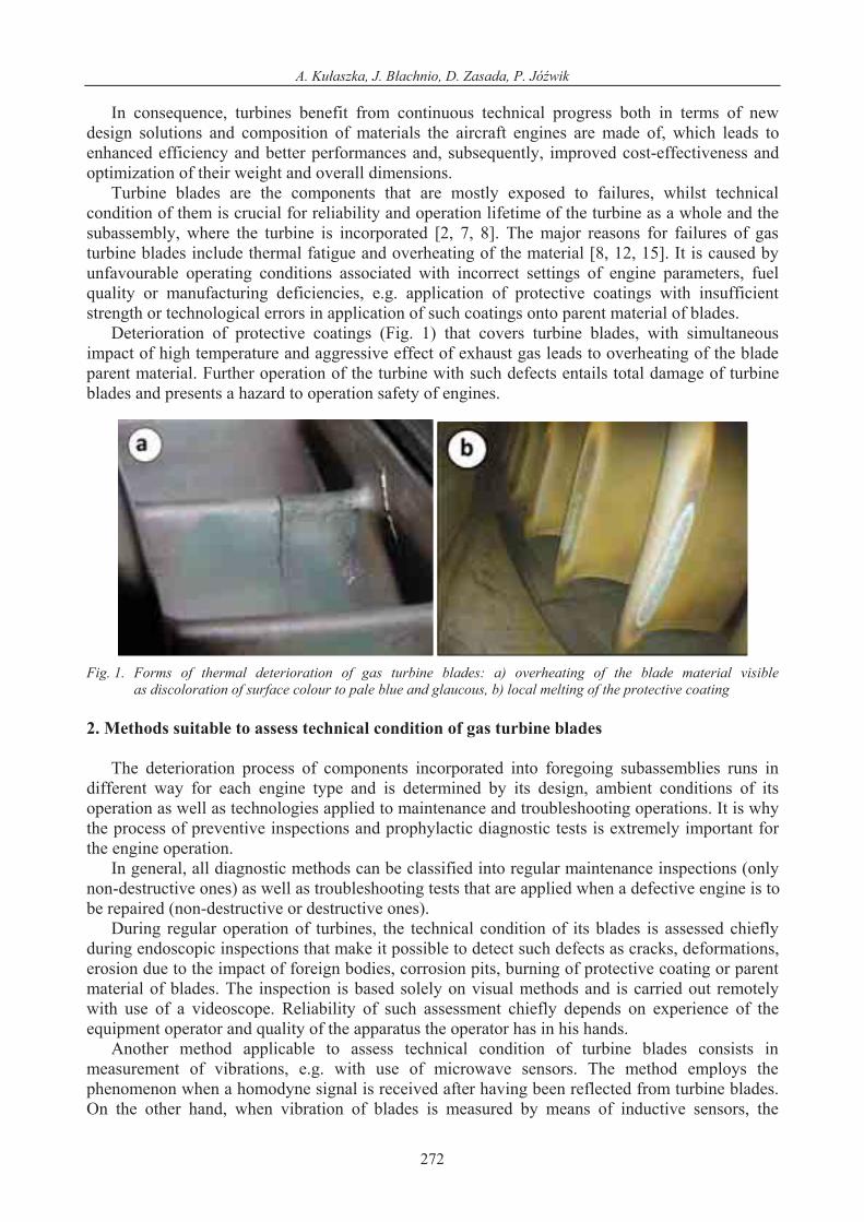
Deterioration of protective coatings (Fig. 1) that covers turbine blades, with simultaneous impact of high temperature and aggressive effect of exhaust gas leads to overheating of the blade parent material. Further operation of the turbine with such defects entails total damage of turbine blades and presents a hazard to operation safety of engines.
Fig. 1. Forms of thermal deterioration of gas turbine blades: a) overheating of the blade material visible as discoloration of surface colour to pale blue and glaucous, b) local melting of the protective coating
2. Methods suitable to assess technical condition of gas turbine blades
The deterioration process of components incorporated into foregoing subassemblies runs in different way for each engine type and is determined by its design, ambient conditions of its operation as well as technologies applied to maintenance and troubleshooting operations. It is why the process of preventive inspections and prophylactic diagnostic tests is extremely important for the engine operation.
In general, all diagnostic methods can be classified into regular maintenance inspections (only non-destructive ones) as well as troubleshooting tests that are applied when a defective engine is to be repaired (non-destructive or destructive ones).
During regular operation of turbines, the technical condition of its blades is assessed chiefly during endoscopic inspections that make it possible to detect such defects as cracks, deformations, erosion due to the impact of foreign bodies, corrosion pits, burning of protective coating or parent material of blades. The inspection is based solely on visual methods and is carried out remotely with use of a videoscope. Reliability of such assessment chiefly depends on experience of the equipment operator and quality of the apparatus the operator has in his hands.
Another method applicable to assess technical condition of turbine blades consists in measurement of vibrations, e.g. with use of microwave sensors. The method employs the phenomenon when a homodyne signal is received after having been reflected from turbine blades. On the other hand, when vibration of blades is measured by means of inductive sensors, the
272

The Assessment of Changes in the Microstructure of a Gas Turbine Blade with a Non-Destructive Thermographic Method
method of measurements is based on variations of the magnetic field caused by rotating turbine blades that interfere with the field. The direct method is used to check condition of the edges of blades installed on the aircraft fuselage with use of eddy-current sensors.
Troubleshooting and repairing processes offer easier access to turbine blades, therefore their technical condition can be assessed more accurately by direct investigation. The scope of non-destructive test methods includes visual inspection, dye penetration, ultrasonic tests and X-ray imaging.
However, all these methods proved insufficient to enable unambiguous assessment how structure of blade material is altered due to overheating. The assessment of overheating status is still performed by visual inspection and consequential decisions are then verified by metallographic investigations. 3. Thermographic methods
Thermographic methods [3, 5, 11] are rated among innovative and rapidly developing non-destructive diagnostic procedures since they enable to measure spot temperatures and then to develop a map of temperature distribution based on detection of infrared radiation emitted by the surface under examination. ‘Thermography’ in dedicated studies is frequently referred to as ‘thermovision’.
Power of electromagnetic radiation emitted by surface of a specific solid body within the entire range of spectrum depends on the surface temperature and peaks of radiation power are located within the infrared bandwidth. The infrared radiation falls into the range of electromagnetic radiation with the wavelength from 0.75 to 100 m, which is outside the very narrow window (from 0.4 to 0.7 m) that is visible for human eye. When an appropriate detector of infrared radiation is available and the relationship between the radiation power and temperature of the heat-emitting surface is known together with the characteristic curve for the output signal of the detector as the function of that radiation power it is possible to find out surface temperature in a touchless manner. Similarly, to other methods of non-destructive tests the infrared thermography technique can be classified into a passive and an active option. 3.1. Active infrared thermography
The essence of active thermography consists in determination of thermal response received from a material already stimulated with an external pulse of heat [11]. Nowadays an intense growth of interest is witnessed to research studies on application of active infrared thermography to detection of flaws in surface-adjacent layer of materials. When some amount of energy is delivered to the material surface, e.g. in the form of a pulse of heat, the surface temperature begins to change rapidly when the stimulation is ended. Owing to diffusion of heat, the thermal front starts travelling towards deeper layers of the material. The presence of areas that differ in thermal properties (containing flaws) from the ones without such flaws results in variation of the diffusion velocity (Fig. 2).
t2
TB = TA
TBTA
t1 t4 (equilibrium)
t3
TB > TA
TB TA
defect
Time
Fig. 2. Variation of the surface temperature of a sample after stimulation with an external pulse of heat [5]
273

A. Ku aszka, J. B achnio, D. Zasada, P. Jó wik
Thus, monitoring of the temperature field on the material sample that is being cooled down enables location of flaws. The simplest method suitable to process the respond signal recorded by means of an infrared thermograph during cooling down the surface under test consists in computation of the temperature contrast [5, 11] that is defined by the following relationship:
Ca(t)=Tp(t)-Tpj(t), (1) where: Ca(t) – absolute contrast, Tp(t) – temperature at a discrete point on the surface under test, Tpj(t) – temperature at the corresponding point over the homogenous (flawless) material.
The values of an absolute contrast are positive at surface locations over the areas of the material that may contain flaws. With regard to the stimulation method several options of the active stimulation can be distinguished, including the pulsed thermography, the lock-in thermography with modulated heating and the pulsed phase thermography) [5].
The pulsed thermography is considered as a relatively simple technique of the active thermography. It consists in determination and analysis of the temperature distribution over the surface under test when it is being cooled down after preliminary uniform heating by means of a thermal pulse (Fig. 3). Monitoring of the temperature field on the surface of the cooling sample makes it possible not only to analyze discontinuities in the cooling sample but also to detect unfavourable amendments to the microstructure of the material under test.
The thermal diffusivity, a, is the basic physical parameter that is indispensable to determine variable and time-dependent fields and gradients of temperature. The diffusivity is directly related to such an important thermophysical parameter as the thermal conductivity . However, it must be mentioned that the thermal conductivity defines the material as a thermal conductor under steady conditions of heat exchange, whilst the thermal diffusivity represents the criterion for a specific material under transient conditions of heat exchange.
Thermal diffusivity of a, of immobile, isotropic and opaque solids, with the density of , the specific heat under constant pressure Cp and at presence of external heat sources with their productivity of qv is usually a function with the values that substantially depend on temperature, i.e. T (x,y,z,t). The time and space distribution of that function is defined by the Fourier-Kirchhoff equation [11]. For the Cartesian coordinate system the equation adopts the following form:
Fig. 3. Application diagram for the pulsed thermography [5]
274

The Assessment of Changes in the Microstructure of a Gas Turbine Blade with a Non-Destructive Thermographic Method
p
v
p C
q
z
T
y
T
x
T
TCTa
t
T222
2 1 . (2)
Upon the assumption that thermal conductance is constant for a specific material ( =const), and no internal heat source exists in the medium, the equation (2) adopts the form:
Ta
t
T 2 . (3)
Thermal diffusivity, a, is the measure how well the specific material is able to conduct heat (i.e. reflects its thermal conductance) and how much heat that medium is able to accumulate (i.e. is associated with the thermal capacitance). Therefore, it can be expressed by means of the following formula:
pCa . (4)
As one can see, higher values of thermal diffusivity, a, of the material entail acceleration of the phenomenon associated with equalization of temperature as a function of time.
When the material comprises flaws, diffusion velocity drops down. Consequently, the surface temperature over a flaw is different from the temperature of areas that are free of flaws – the foregoing interrelationship changes its nature. For instance, such a defect as delamination of plies in sandwich materials can be revealed by plotting the corresponding graph ln(T-T0) = ln(t) (Fig. 5). For homogenous materials, the graph presents a straight line with its slope of 1/2.
3
3.5
4
4.5
5
5.5
6
6.5
7
4 5 6 7 8 9 1
ln(t)
ln(T
- T
o)
0
r = 5 m m
r = 1 cm
r = 8 m m
wall
s lope = -0.5
D1 D2 D3
r=5 mm r = 8mm r = 10 mm
Fig. 4. Detection of delamination by means of the pulsed thermography [5]
Obviously, this method, similarly to other one, has its limitations, as it enables to detect flaws only in surface-adjacent layers of materials due to the fact that temperature contrast rapidly fades out in pace with the depth of penetration [11]. The completed studies demonstrated that flaws located in deeper layers are manifested some later and the contrast is much lower. Actually, the time of td between terminations of the thermal pulse until the moment when flaws are revealed is proportional to the square of the depth z of the flaw location.
2ztd
. (5)
Whilst the contrast of C rapidly decreases in pace of the flaw depth.
275

A. Ku aszka, J. B achnio, D. Zasada, P. Jó wik
3
1
zC . (6)
The experiments made it also possible to find out that the radius of the smallest detectable flaw must be at least twice as big as the depth where the flaw is located.
The drawback of the pulse thermography is the requirements that the examined surface must be homogenous in terms of heat emission, which entails the need to have it coated before examination with uniform films, e.g. graphite. The drawback is not existent for test methods that base on another parameter, i.e. the phase angle of thermal wave. This approach is applied to the method of the lock-in thermography with modulated heating and the pulsed phase thermography. 3.2. Pulse thermography
The pulse thermography has already been applied to a series of research studies, including the
ones intended to assess applicability of the method to examine obstruction-free condition of cooling ducts for turbine blades. The overall improvement of the turbine efficiency and increase of the power factor are directly related to the temperature of exhaust gas. Since elevation of this temperature lead to problems with the material strength, interiors of turbine blades must be cooled down with airstreams that pass through labyrinths of air ducts with sophisticated shapes. It is the design solution that makes the manufacturing process of turbine blades more difficult as well as diagnostics of their technical condition. Operational experience and examination of turbine blades at overhaul workshops demonstrated that a frequent reason for their damages, besides defects of materials, are disturbances in their internal cooling system caused by insufficient throughput of cooling ducts. Fig. 5 shows images of a typical blade, where imaging was carried out by means of a conventional optical method, the RAW method as well as the Thermographic Signal Reconstruction (TSR) method that is implemented to tomography devices. Application of the pulse thermography with accordingly developed software makes it possible easily inspect the internal system of blade ducts (the labyrinth) and lack of congestions. The advantage of this method over the X-ray inspection is the lack of dangerous radiation the test engineer is exposed to, hence no special test rooms with radiation-proof insulation are necessary for execution of tests. The unit prices of thermographic inspection are lower as no expensive consumable must be purchased. The waiting time until test results are available is also shorter. Another method that is based on measurements of fluid volume that passes through cooling channels of blades is less accurate and more time-consuming as compared to thermographic tests.
Fig. 5. Images for blades of high-pressure (HP) turbine incorporated into an avionic engine and examined with use of various methods: visual (optical) inspections, RAW and TSR techniques [5]
276
The Assessment of Changes in the Microstructure of a Gas Turbine Blade with a Non-Destructive Thermographic Method
3.3. Results of thermographic tests completed for blades of gas turbines heated at presence of exhaust gas from aviation kerosene
Examination of turbine blades with use of the pulse thermography enables to detect
discontinuities of the material in the subsurface layers and to assess alterations of microstructures in blades of a gas turbine.
The tests were carried out for new rotor blades of a gas turbine being a part of an avionic turbojet engine. The blades were made of the EI–867 WD alloy. They receive no artificial cooling during operation in the engine. The manufacturing process of blades includes metal forming. The blade alloy belongs to a very scarce group of alloys that are free of titanium and reduced content of chromium that makes it susceptible to corrosion. It is why the blades are coated with protective layers of aluminium deposits. The TU 14-1-232-72 standard (technical conditions) specifies requirements with regard to chemical composition of the EI–867 WD superalloy (Tab. 1).
Tab. 1 Percentage chemical breakdown of the EI–867 WD alloy according to the Russian standard HN62MWKJu
C Mo Si Cr Ni Co Mo W Al B Fe Other
max max max max
0.1 0.3 0.6 9.0 Rest
14 10.3 5.0 4.5 0.02 4.0 0.3 V, 01 Ba max
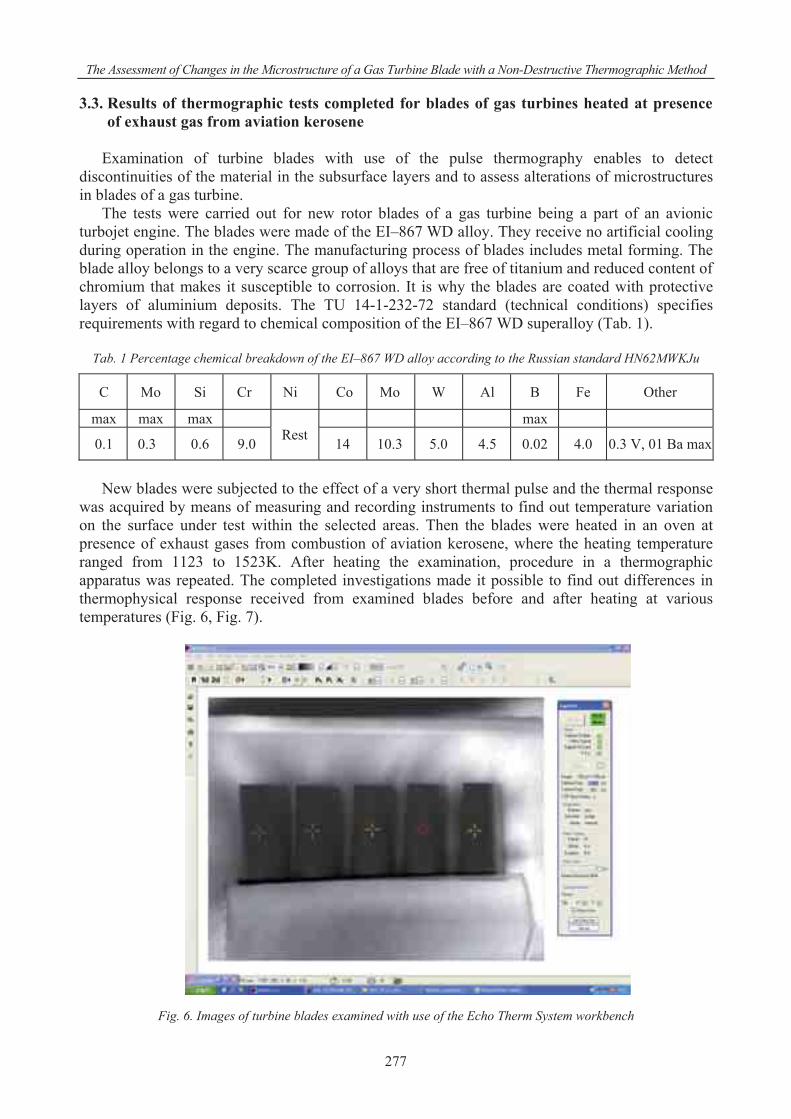
New blades were subjected to the effect of a very short thermal pulse and the thermal response
was acquired by means of measuring and recording instruments to find out temperature variation on the surface under test within the selected areas. Then the blades were heated in an oven at presence of exhaust gases from combustion of aviation kerosene, where the heating temperature ranged from 1123 to 1523K. After heating the examination, procedure in a thermographic apparatus was repeated. The completed investigations made it possible to find out differences in thermophysical response received from examined blades before and after heating at various temperatures (Fig. 6, Fig. 7).
Fig. 6. Images of turbine blades examined with use of the Echo Therm System workbench
277

A. Ku aszka, J. B achnio, D. Zasada, P. Jó wik
Fig. 7. The graph ln(T-To) = ln(t) for the response of turbine blades to a heat pulse – a new one and the blades
heated at the temperatures of 1123 K, 1323 K and 1523 K
The completed metallographic investigations of blades heated at various temperatures evidenced that high temperature leads to alterations of microstructures, both of the coating material and the EI–867 WD alloy, where gradual growth of the aluminium protective coating is observed in pace with the temperature growth (Fig. 8).
Fig. 8. The graph for the thickness of aluminium coating on turbine blades – a new one and the blades heated at the temperatures of 1123 K, 1323 K and 1523 K
The graph demonstrated that heat resistance of blades subjects to deterioration. The growth of
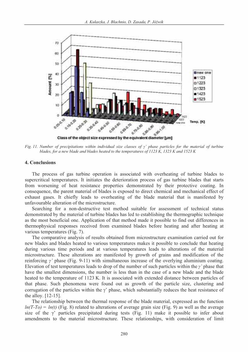
grains by more than 50% is observed in the alloy microstructure (Fig. 9), which adversely affects mechanical properties of the alloy [4, 13]. In particular, these alterations are clearly visible within the reinforcing ’ phase as modification of the structure is observed for that phase (Fig. 10, 11). The temperature of 1123 K is conducive to growth of small particles within the ’ phase. At the temperature of 1323 K, mid-sized particles of that phase expand. Finally, at the temperature of 1523 K the particles with the largest initial size exercise further growth due to coagulation. In consequence, the number of particles with the fines sizes gradually decreased in pace with the temperature growth and is much less than in the material of new blades and the ones subjected to heating at the temperature of 1123 K. At the same time the distance between individual particles of the ’ phase is getting larger and larger. The revealed growth, clustering and corrugation of particles within the ’ phase leads to substantial deterioration of heat resistance demonstrated by
278

The Assessment of Changes in the Microstructure of a Gas Turbine Blade with a Non-Destructive Thermographic Method
the alloy [10, 13]. When the number of particles developed to the ’ phase is adopted as the criterion of the material applicability for further operation, one is able to determine a threshold limit for the blade lifetime.
Fig. 9. Alteration of the average grain size for the EI-867WD alloy used to manufacture the turbine blades, for a new
blade and blades heated at various temperatures. The average grain size is expressed as the diameter of an equivalent circle with the same surface as of the grain
Fig. 10. The microstructure of blades heated for 2 hours at the temperatures of a) – 1123K, b) - 1323K, c) – 1523K (magn. x 20,000) – visible effects of coagulation, alteration of particle shapes and corrugation of particles within the ’ phase
279
A. Ku aszka, J. B achnio, D. Zasada, P. Jó wik
Fig. 11. Number of precipitations within individual size classes of ’ phase particles for the material of turbine
blades, for a new blade and blades heated to the temperatures of 1123 K, 1323 K and 1523 K 4. Conclusions
The process of gas turbine operation is associated with overheating of turbine blades to
supercritical temperatures. It initiates the deterioration process of gas turbine blades that starts from worsening of heat resistance properties demonstrated by their protective coating. In consequence, the parent material of blades is exposed to direct chemical and mechanical effect of exhaust gases. It chiefly leads to overheating of the blade material that is manifested by unfavourable alteration of the microstructure.
Searching for a non-destructive test method suitable for assessment of technical status demonstrated by the material of turbine blades has led to establishing the thermographic technique as the most beneficial one. Application of that method made it possible to find out differences in thermophysical responses received from examined blades before heating and after heating at various temperatures (Fig. 7).
The comparative analysis of results obtained from microstructure examination carried out for new blades and blades heated to various temperatures makes it possible to conclude that heating during various time periods and at various temperatures leads to alterations of the material microstructure. These alterations are manifested by growth of grains and modification of the reinforcing ’ phase (Fig. 9-11) with simultaneous increase of the overlying aluminium coating. Elevation of test temperatures leads to drop of the number of such particles within the ’ phase that have the smallest dimensions, the number is less than in the case of a new blade and the blade heated to the temperature of 1123 K. It is associated with extended distance between particles of that phase. Such phenomena were found out as growth of the particle size, clustering and corrugation of the particles within the ’ phase, which substantially reduces the heat resistance of the alloy. [12-15].
The relationship between the thermal response of the blade material, expressed as the function ln(T-To) = ln(t) (Fig. 8) related to alterations of average grain size (Fig. 9) as well as the average size of the ’ particles precipitated during tests (Fig. 11) make it possible to infer about amendments to the material microstructure. These relationships, with consideration of limit
280

The Assessment of Changes in the Microstructure of a Gas Turbine Blade with a Non-Destructive Thermographic Method
thresholds for the permitted alterations, make it possible to state by means of only the non-destructive tests whether the turbine blades are suitable for further operation or not. References [1] B achnio, J., Examination of changes in microstructure of turbine blades the use of non-
destructive methods, Journal of Polish CIMAC, Vol. 5, No. 2, 2010. [2] B achnio, J., Pawlak, W. J., Damageability of gas turbine blades - evaluation of exhaust gas
temperature in front of the turbine using a non-linear observer. Advances in Gas Turbine Technology, InTech, 2011.
[3] Carl, V., Becker, E., Sperling, A., Thermography inspection system for gas turbine blades, 7th European Conference on non-destructive testing, Copenhagen 1998.
[4] Dubiel, B., Zmiany mikrostruktury podczas pe zania monokrystalicznych nadstopów niklu, AGH, Rozprawy, Monografie Nr 235, Kraków 2011.
[5] EchoTherm User Manual, Thermal Wave Imaging, Inc. 2009. [6] Hodor, K., Struktura gradientowa warstwy wierzchniej nadstopów na bazie Ni i Fe-Ni,
Rozprawa doktorska, Akademia Górniczo-Hutnicza, Kraków 2002. [7] Karczewski, Z., Endoscopic diagnostics of marine engines, Diagnostyka, 3(47), 2008. [8] Ku aszka, A., Chalimoniuk, M., Sprawozdania z prac badawczych, Wyd. ITWL, Warszawa
2000-2011 (niepublikowane). [9] Lewitowicz, J., Podstawy eksploatacji statków powietrznych, T.4, Wyd. ITWL, Warszawa
2008. [10] Majka, H., Sieniawski, J., Badania kinetyki i koagulacji fazy ' w superstopie niklu
EI-867, Archiwum Nauki o Materia ach, T. 4, Nr 4, 1998. [11] Oliferuk, W., Termografia podczerwieni w nieniszcz cych badaniach materia ów i urz dze ,
Biuro Gamma, Warszawa 2008. [12] Paton, B., aroprocznost litiejnych nikieliewych sp awow i zaszczuta ich ot okislienija,
Naukowa Dumka, Kijew 1997. [13] Pozna ska, A., ywotno opatek silników lotniczych ze stopu EI-867 w aspekcie
odkszta cenia niejednorodnego i zmian strukturalnych, Rozprawa doktorska. Politechnika Rzeszowska, Rzeszów 2000.
[14] Szczotok, A., Chmiela, B., Soza ska, M., Grain Imaging and Measurement on Cross-Section of Turbine Blade Using EBSD and Optical Methods, In ynieria Materia owa, Nr 1, 2009.
[15] Tajra, S., Otani, R., Tieorija wysokotiempieraturnoj procznosti matieria ow, Mieta urgija, Moskwa 1986.
281
