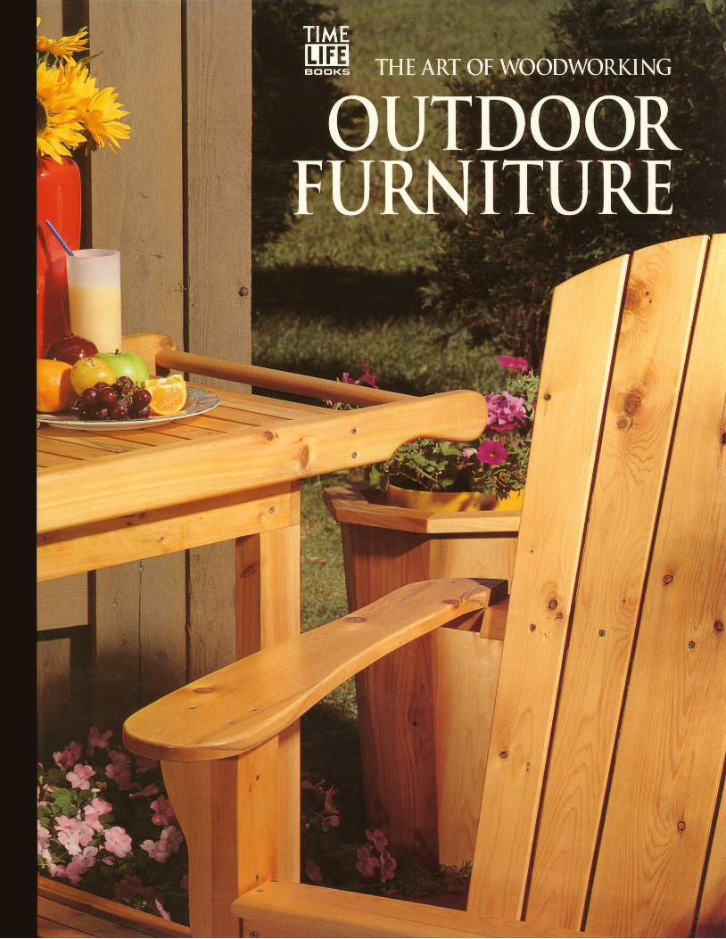
the art of woodworking - outdoor furniture
TRANSCRIPT

IItIItI
THE ART OF WOODWORKING
HOMEWORI$HOP
WORKSHOP GUIDE
TABLE SAW SAFETY TIPS
. Use a sa fe ty guard whenever poss ib le . . Do no i s ta r t a cu t un t i l the b lade is run- r Use the r ip fence or the mi te r gauge fo r
Before mak ing a beve l cu t , con f i rm tha t n ing a t fu l l speed. a l l cu t t ing opera i ons ; never a t tempt to
the guard w i l l be c lear o f the b lade. cu t f reehand.. Before us ing the saw each t ime, inspec t
. Do not leave the saw running when rt is rts safety features. Make sure there is no . Before r ipp ng a board, ensure that the
unat tended. b ind ing or misa l ignment o f mov ing par ts . edge in contac t w i th the r ip fence is smooth
Do not use the saw unti l such problems and completely straight and that the suro l f you are interrupted, complete the are corrected. face against the table is f lat.
opera t ion under way be fore tu rn ing o f fthe saw and look ing up , . A lways feed wood in to the saw b lade o Stand to one s ide o f any workp iece dur
aga ins t the d i rec t ion o f b lade ro ta t ion . ing any cu t t ing opera t ion so you w i l l no to Fo l low the manufac turer ' s ins t ruc t ions be in ju red in case o f k ickback .
to change accessor ies ; unp ug the saw . l v lake sure the r ip fence is locked
f i rs t . Make sure tha t saw b lades and cu t in pos i t ion be fore r ipp ing . r l f you have to reach pas t the b lade,
te rs a re sharp , c lean and undamaged. make sure to keep your hands a t leas t.Do no t use the mi te r gauge in combina- 3 inches away f rom i t ,
o Before cu t t ing a workp iece , remove t ion wt th the r ip fence to make a cu l
any loose knots f rom i t us ing a hammer . except when the b lade does no t cu t r Use a wooden s t rck , ra ther than your
Inspec t sa lvaged wood fo r nar ls and comple te ly th rough the workp iece , such f ngers , to c lear wood scraps f rom the
screws before cutt ing. as for a dado or a groove. saw table.
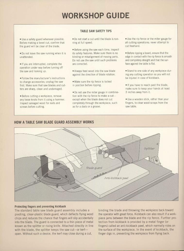
HOW A TABLE SAW BLADE GUARD ASSEMBLY W()RKS
IIIIIIIII
III
IItI
IIIIIII
Protecting fingers and preventing kickbackThe s tanda rd t ab le saw b lade gua rd assemb ly i nc ludes apivot ing, c lear-p last ic b lade guard, which def lects f ly ing woodchips and reduces the chance that f ingers wi l l s l ip acc identa l lyin to the b lade. The guard is connected to a th in p iece of metalknown as t he sp l i t t e r o r r i v i ng kn i f e . A t t ached d i rec t l y i n l i newi th the b lade, the spl i t ter keeps the saw cut-or ker f -open. Wi thout such a device, the ker f may c lose dur ing a cut ,
binding the blade and throwing the workpiece back towardthe operator with great force. Kickback can also result if a work-piece jams between the blade and the r ip fence. Further pro-tect ion from kickback is provided by a metal f inger (orf ingers) cal led an ant i-k ickback pawl, which normal ly r ides onthe surface of the workpiece. In the event of k ickback, thef inger digs in, prevent ing the workpiece from f ly ing back.
I
OUTDOORFURNITURE
tIIIIIIIIIIIIIIIIIIIIIIIIItIIIIt
IIII
IIIIIIIIIIIIIIIIIIIIIIIItIIt
THE ART OF WOODVVORKING
OLITDOOR
ST. REMY PRESSMONTREAL
FURNITURE
TIME-LIFE BOOKSALEXANDRIA, VIRGINIA
PUBLISHERPRESIDENT
Series EditorSeries Art Director
Senior EditorEditor
Art DirectorsDesigners
Picture EditorWriters
C o n tr ib u tin g I llu str ato r s
AdministratorProduction Manager
CoordinatorSystem Coordinator
PhotographerIndexer
Kenneth WinchesterPierre L6veilld
Pierre Home-DouglasFrancine LemieuxMarc CassiniAndrew JonesJean-Pierre Bourgeois, Solange LabergeHdldne Dion, fean-Guy Doiron,Francois DaxheletChristopher JacksonJohn Dowling, Adam Van SertimaGilles Beauchemin, Michel Blais,Ronald Durepos, Michael Stockdale,James Th6rienNatalie WatanabeMichelle TurbideDominique Gagn6Eric BeaulieuRobert ChartierChristine M. Jacobs
THE ART OF WOODWORKING was produced byST.REMYPRESS
THECONSULTANTS
Craig Gilborn is the former director of the AdirondackMuseum in Blue Mountain Lake, NewYork. He is also a builderof outdoor furniture and author of AdirondackAnd RusticFumitur e, p:ubl.ished by Abrams.
Giles Miller-Mead taught advanced cabinetmaking at Montrealtechnical schools for more than ten years. A native of NewZealand,he has worked as a restorer ofantique furniture
The Art of woodworking. Outdoor furniture.D. Cm. -
Inciudes index.ISBN 0-8094-9543-0l. Outdoor furniture.2. Furniture making.3. Garden ornaments and furniture. I. Time-LifeBooks. II. Series: Art of Woodworking.TTI97.5.09A78 1995684.1'8-dc20 95-35782
CIP
For information about any Time-Life book,please call I -800-621-7 026, or write:Reader InformationTime-Life Customer ServiceP.O. Box C-32068Richmond, Virginia2326r-2068
@ 1996 Time-Life Books Inc.All rights reserved.No part of this book may be reproduced in any form or byany electronic or mechanical means, including informationstorage and retrieval devices or systems, without prior writ-ten permission from the publisher, except that brief passagesmay be quoted for reviews.Second printing 1999. Printed in U.S.A.Published simultaneously in Canada.
TIME-LIFE is a trademark of Time Warner Inc. U.S.A.
IItI
IItIIIIIIIItIIIIIIIIIIIIIIII
Time-Life Books is a division of Time Life Inc.
TIMELIFEINC.
President and CEO George Artandi
TIME-LIFEBOOKS
P ub lish er / M an a gin g E dit o r
Director of MarketingConsubingEditor
Director of Editorial AdministrationDirectors of Book Production
Production ManagerQuality Assurance Manager
Neil Kagan
Wells P. Spencelohn R. SullivanBarbara LevittMarjann Caldwell, Patricia PascaleKen SabolJames King
CONTENTS
L2T4
L61 820
6 INTRODUCTION
FACING THE ELEMENTSA gallery of outdoorfurniture designsSelecting wood|oinery and hardwareFinishing
CHAIRSAnatomy of an Adirondack chairBuilding an Adirondack chairAnatomy of a curved chairFashioning a curved chairAnatomy of a lounge chairMaking a lounge chair
BENCHESAnatomy of a garden benchBuilding a garden benchPark benchAnatomy of a tree benchBuitding a tree bench
TABLESPatio tableFolding picnic table and benchMaking a folding picnic tableKeyed tenon bench
IO2 SWINGSAND GLIDERS104 Anatomy of a porch swing106 Building a porch swingII2 Anatomy of a glider baseII4 Building a glider base
ll8 GARDEN PROJECTSI20 Anatomy of an eight-sided
planterI2I Building an eight-sided planter126 Anatomy of a serving trolleyI27 Fashioning a serving trolley131 Anatomy of a garden arborI32 Building a garden arbor
I4O GLOSSARY
I42 INDEX
T44 ACKNOWLEDGMENTS
22242634364446
545658647072
7880909298
INTRODUCTION
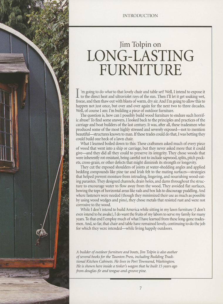
Iim Tolpin on
LONG-LASTINGFI.]RNITI-IRE
f 'm
going to do what to that lovely chair and table set? Well, I intend to expose itI to the direct heat and ultraviolet rays of the sun. Then I'll let it get soaking wet,freeze, and then thaw out with blasts of warm, dry air. And I'm going to allow this tohappen not just once, but over and over again for the next two to three decades.Well, of course I am: I'm building a piece of outdoor furniture.
The question is, how can I possibly build wood furniture to endure such horrif-ic abuse? To find some answers, I looked back to the principles and practices of thecarriage and boat builders of the last century. It was, after all, these tradesmen whoproduced some of the most highly stressed and severely exposed-not to mentionbeautiful-structures known to man.If these trades could do that,I was betting theycould build one heck of a lawn chair.
\Ahat I learned boiled down to this: These craftsmen asked much of every Dreceof wood that went into a ship or carriage, but they never asked more that it couldgive-and they did all they could to preserve its integrity. They chose woods thatwere inherently rot-resistant, being careful not to include sapwood, splits, pitch pock-ets, cross-grain, or other defects that might diminish its strength or longevity.
They cut the exposed shoulders of joints at water-shedding angles and appliedbedding compounds like pine tar and Irish felt to the mating surfaces-strategiesthat helped prevent moisture from intruding,lingering, and nourishing wood-eat-ing parasites. They designed channels, drain holes, and dams throughout the struc-ture to encourage water to flow away from the wood. They avoided flat surfaces,bowing the tops of horizontal areas like rails and box lids to discourage puddling. Andwhere fasteners were needed (though they minimized their use as much as possibleby using wood wedges and pins), they chose metals that resisted rust and were notcorrosive to the wood.
While I don't intend to build America while sitting in my lawn furniture (l don'teven intend to be awake), I do want the fruits of my labors to sele my family for manyyears. To that end I employ much of what I have learned from these long-gone trades-men. And, so far, that chair and table have remained lovely, continuing to do the jobfor which they were intended-while living happily outdoors.
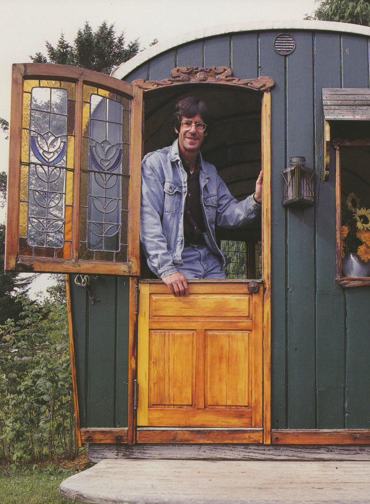
A builder of outdoor furniture and boats, Jim Tolpin k also authorof several books for the Taunton Press, including Building Tradi-tional Ktchen Cabinets. He lives in Port Townsend, Washington.He is shown here inside q tinker's wagon that he built 15 years agofrom douglas-fir and tongue-and-groove pine.
INTRODUCTION
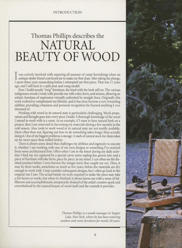
Thomas Phillips describes the
NATURALBEAUTYOFWOODf *ur actively involved with repairing all manner of camp furnishings when anI antique dealer friend convinced me to make my first chair. After taking the plunge,I spent three years researching before I attempted my first piece. That was 11 yearsago, and I still have it: a split post-and-rung model.
Now I build mostly"twig" furniture, the kind with the bark still on. The variousindigenous woods I work with provide me with color, form, and texture, allowing anartistic freedom of expression virtually unlimited by straight lines. Originally thiswork evolved to complement my lifestyle, and it has since become a very rewardingsideline, providing a business and personal recognition far beyond anything I everdreamed of.
Working with wood in its natural state is particularly challenging. Much prepa-ration and thought goes into every piece I build. A thorough knowledge of the woodI intend to work with is a must. As an example, if I want to have natural bark on aproject, then I am restricted to harvesting my materials during a few months in thecold season. Also, tools to work wood in its natural state are not readily available.More often than not, figuring out how to do something takes longer than actuallydoing it. One of my biggest problems is storage: A stash of natural stock for chairs takesup far more space than milled limber.
There is always some detail that challenges my abilities and ingenuity to executeit, whether I am working with one of my own designs or something I've receivedfrom some architectural firm. Often when I am in the forest during my daily activ-ities I find my eye captured by a special curve some sapling has grown into and apiece of furniture will take form, piece by piece, in my mind. I can often see the fin-ished product before I even harvest the unique form that caught my eye. Then, itmay be three weels, sometimes as much as five years, before the materials are dryenough to work with. I may consider subsequent designs, but I often go back to theoriginal one I saw. The actual hands-on work required to make the piece may takea few hours or weeks, but when it's finished, it always leaves me with a sense of ful-fillment and accomplishment, temporarily drained of the artist's creative spark andoverwhelmed by the natural beauty of wood itself and the warmth it provides.
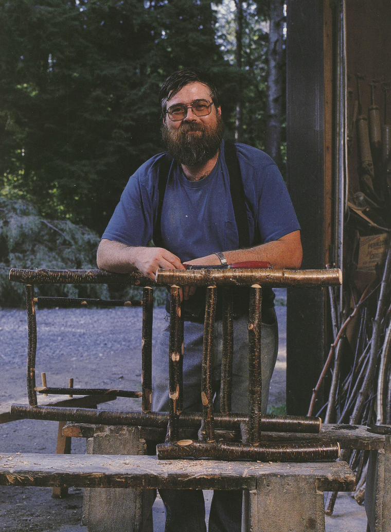
Thomas Phillips is awoods manager in TupperLake, New Yoil<" where he has been restoring
outdoor and rustic furniture for neaily 20 years.
tLI
tII
INTRODUCTION
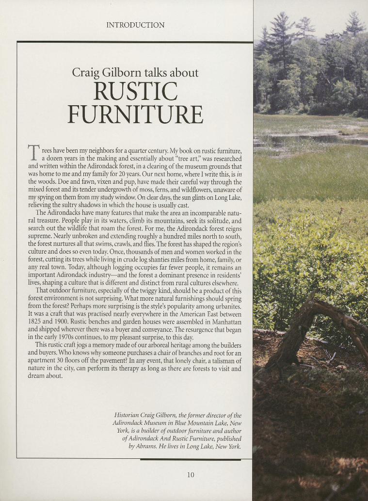
Craig Gilborn talks about
RUSTICFURNITURE
f rees have been my neighbors for a quarter century. My book on rustic furniture,I a dozen years in the making and essentially about "tree artj'was researched
andwritten within theAdirondack forest, in a clearing of the museum grounds thatwas home to me and my family for 20 years. Our next home, where I write this, is inthe woods. Doe and fawn, vixen and pup, have made their careful way through themixed forest and its tender undergrowth of moss, ferns, and wildflowers, unaware ofmyspying on them from mystudywindow. On clear days, the sun glints on l,ong lake,relieving the sultry shadows in which the house is usually cast.
The Adirondacks have many features that make the area an incomparable natu-ral treasure. People play in itswaters, climb its mountains, seek its iolitude, andsearch out the wildlife that roam the forest. For me, the Adirondack forest reignssupreme. Nearly unbroken and extending roughly a hundred miles north to south,the forest nurtures all that swims, crawls, and flies. The forest has shaped the regiontculture and does so even today. Once, thousands of men and women worked in theforest, cutting its trees while living in crude log shanties miles from home, family, orany real town. Today, although logging occupies far fewer people, it remains animportant Adirondack industry-and the forest a dominant presence in residents'lives, shaping a culture that is different and distinct from rural cultures elsewhere.
That outdoor furniture, especially of the twiggy kind, should be a product of thisforest environment is not surprising. What more natural furnishings should springfrom the forest? Perhaps more surprising is the stylet popularity among urbanites.It was a'craft that was practised nearly everywhere in the American East between1825 and 1900. Rustic benches and garden houses were assembled in Manhattanand shipped wherever there was a buyer and conveyance. The resurgence that beganin the early 1970s continues, to my pleasant surprise, to this day.
This rustic craft jogs a memory made of our arboreal heritage among the buildersand buyers. Who knows why someone purchases a chair of branches and root for anapartment 30 floors offthe pavement? In any event, that lonely chair, a talisman ofnature in the ciry can perform its therapy as long as there are forests to visit anddream about.
Historian Craig Gilborn, the former director of theAdirondack Museum in Blue Mountain Lake, New
York, is a builder of outdoor furniture and authorof Adirondack And Rustic Furniture, published
by Abrams. He lives in Long Lake, Narv York.

,t*fl;
7 .- s; t
CI
e
{D' {Q
I' a
IIIIIa
F
tIIIII
ilt';, :l i . . r l . i Iii u;4.;, I;'.;'tj,,
' r
II
tIrIIIItIIIIIIIIIIIIIIIttI
II
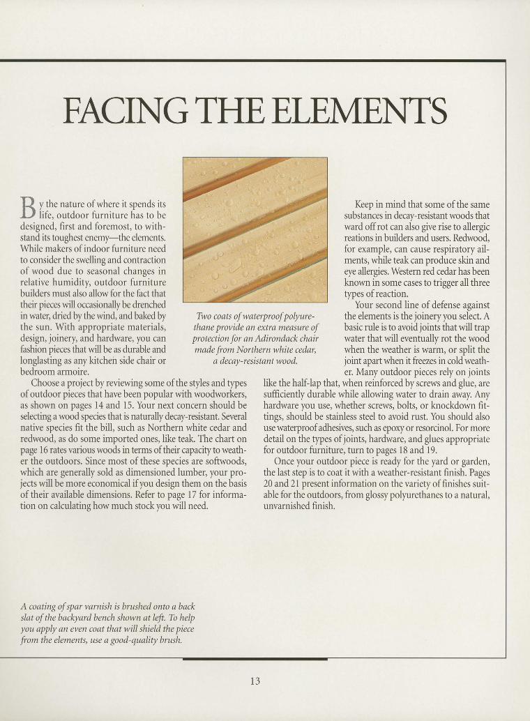
Two coats of waterproof polyure-thane provide 0n extra measure ofprotection for an Adirondack chairmade from Northern white cedar,
a decay-resistant woo d.
Keeo in mind that some of the samesubstances in decay-resistant woods thatward offrot can also give rise to allergicreations in builders and users. Redwood,for example, can cause respiratory ail-ments, while teak can produce skin andeye allergies. Western red cedar has beenknown in some cases to trigger all threetypes ofreaction.
Your second line ofdefense againstthe elements is the joineryyou selict. Abasic rule is to avoid joints that will trapwater that will eventually rot the woodwhen the weather is warm, or split theioint auart when it freezes in cold weath-er. Many outdoor pieces rely on joints
like the half-lap that, when reinforced by screws and glue, aresufficiently durable while allowing water to drain away. Anyhardware you use, whether screws, bolts, or knockdown fit-tings, should be stainless steel to avoid rust. You should alsouse waterproof adhesives, such as epoxy or resorcinol. For moredetailon the types of joints, hardware, and glues appropriatefor outdoor furniture, turn to pages 18 and 19.
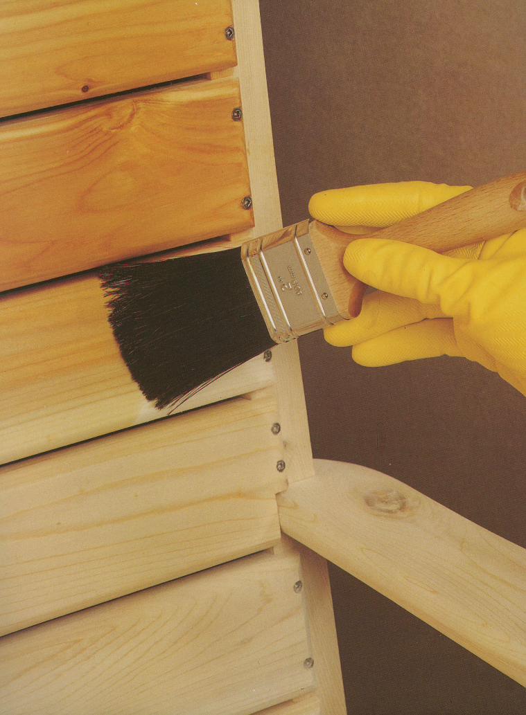
Once your outdoor piece is ready for the yard or garden,the last step is to coat it with a weather-resistant finish. Pages20 and 21 present information on the variety of finishes suit-able for the outdoors, from glossy polyurethanes to a natural,unvarnished finish.
A coating of spar varnish is brushed onto a backslat of the bacleyard bench shown at left. To helpyou apply an eyen coat that will shield the piece
from the elements, use a good-quality brush.
FACING THE ELE,MENTS
y the nature of where it spends itslife, outdoor furniture has to be
designed, first and foremost, to with-stand its toughest enemy-the elements.While makers of indoor furniture needto consider the swelling and contractionof wood due to seasonal changes inrelative humidity, outdoor furniturebuilders must also allow for the fact thattheir pieces will occasionallybe drenchedin water, dried by the wind, and baked bythe sun. With appropriate materials,design, joinery, and hardware, you canfashion oieces that will be as durable andlonglastlng as any kitchen side chair orbedroom armoire.
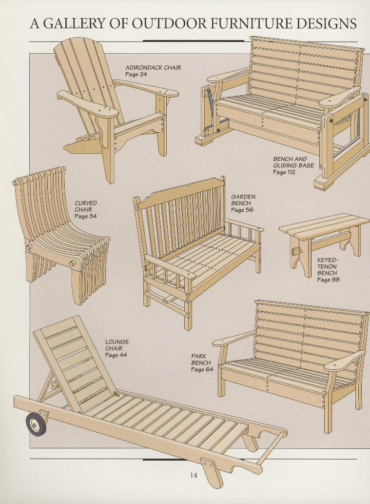
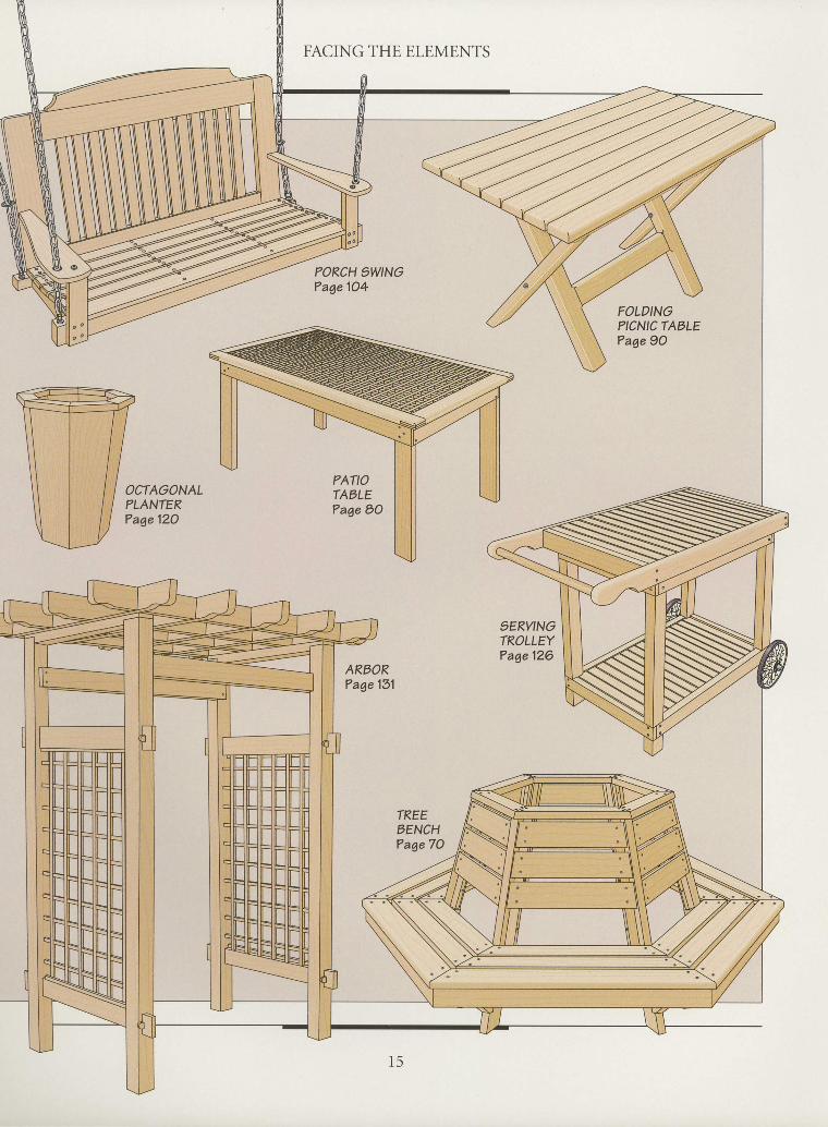
Choose a project by reviewing some of the styles and typesof outdoor pieces that have been popular with woodworkers,as shown on pages 14 and 15. Your next concern should beselecting a wood species that is naturally decay-resistant. Severalnative species fit the bill, such as Northern white cedar andredwood, as do some imported ones, like teak. The chart onpage 16 rates various woods in terms of their capacity to weath-er the outdoors. Since most of these species are softwoods,which are generally sold as dimensionid lumber, your pro-jects willbe more economical ifyou design them on the basisof their available dimensions. Refer to page 17 for informa-tion on calculating how much stock you will need.
1 3
A GALLERY OFI
OUTDOORFURNITUREDESIGNS II
ADIRONDACK CHAIRTage 24
LOUNGECHAIRTage 44
tIIII
tIIIIIIIIIIIIttIII
EENCH ANDOLIDING BASETage 112
CURVEDCHAIR?age34
KEYED.rENONBENCH?age 9O
III
FACING THE ELEMENTS
PORCH 1WINGTage 1O4
OCTAGONALPLANTERTage 12O
IIIIIIIIttII
IIIIIIIII
9ERVINGTROLLEYTage 126
ARBOR?age 131
III
SELECTINGWOOD
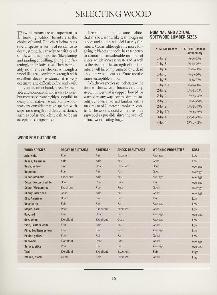
E.* dec is ions are as impor tan t toL bui ldins outdoor lurni ture as thechoice of w6od. The chart below ratesseveral species in terms of resistance todecay, strength, capacity to withstandshock, working properties (like planingand sanding or drilling, gluing, and fas-tening), and relative cost. There is prob-ably no one ideal choice. Although awood like teak combines strength withexcellent decay resistance, it is veryexpensive, and difficult to find and work.Pine, on the other hand, is readily avail-able and economical, and is easy to work,but most species are highly susceptible todecay and relatively weak. Many wood-workers consider native species withsuperior strength and decay resistance,such as cedar and white oak, to be anacceptable compromise.
Keep in mind that the same qualitiesthat make a wood like teak tough onblades and cutters will yield sturdy fur-niture. Cedar, although it is more for-giving to blades and tools, has a tendencyto contain a considerable number ofknots, which increase waste and as wellas the risk that the strength of the fur-niture will be compromised by a deadknot that was not cut out. Knots are alsomore susceptible to rot.
Whichever species you select, take thetime to choose your boards carefully.Avoid lumber that is cupped, bowed, orwarped in any way. For maximum sta-bilitv. choose air-dried lumber with amaximum of 20 uercent moisture con-tent. The wood should contain as littlesapwood as possible since the sap willattract wood-eating bugs.
N()MINAL AND ACTUALSOFTW()OD LUMBER SIZES
NOMlNAt (inches) ACTUAT (inches)Surfaced dry
I-by-Z 3la-by-Itlz
1-by-3 3lq-by-2tlz
1-by-4 3l+by-3tlz
1-by-6 3l+by-5Uz
1-by-8 3lq-by-7rlq
1-by- 10 3lq-by-9tlq
2-by-2 lUz-by-7112
2-by-4 ltlz-by-3112
2-by-6 ltlz-by-5112
2-by-8 lUz-by-7llt
2-by- 10 ltlz-by'9llt
3-by-4 2Uz-by-3rlz
4-by-4 3tlz-by-3rlz
IIIIIIIIIIIIIIIIIIIIIIIIIItItIII
W()OD FOR ()UTDOORS
W()OD SPECIES
Ash, white
Beech, American
Birch, yellow
Butternut
Cedal, alomatic
Cedar, Northern white
Cedar, Western red
Cheny, American
Elm, American
Douglas-fir
Maple, hard
0ak, red
0ak, white
Pine, Eastern white
Pine, Southem yellow
Poplar, yellow
Redwood
Spruce, sitka
Teak
Walnut, black
DECAY RESISTANCE
PoorFai
Fai r
Poor
Excel lent
Good
Excel lent
Good
Good
Fair
Poor
Fai
Excel lent
Fai
Fair
Fai
Excel lent
Poor
Excel lent
Good
STRENGTHFair
Fai r
Good
Fai
Fair
Poor
Poor
Fair
Fai r
Fair
Excel lent
Good
Excel lent
Fair
Fai r
Fav
Poor
Fair
Excel lent
Fair
SHOCK RESISTANCE
Excel lent
Fai r
Excel lent
Fai r
Fai r
Poor
Poor
Fair
Fak
Fai
Excel lent
Fau
Good
Fair
Good
Fair
Poor
Fair
Excel lent
Excel lent
WORKING PR()PERTIESAverageGood
Good
Good
Average
Fa i r
Good
Good
Fai
Average
Good
Average
Average
Good
Average
Good
Good
Average
Fair
Good
c0sTLow
Low
Average
Average
Average
Average
Average
Average
LOW
LOW
LOW
Average
Low
Low
LOW
LOW
Average
Average
High
H igh
1 6
FACING THE ELEMENTS
IIIIIIIItIIIIIIIIIIIIItIIIItIItI
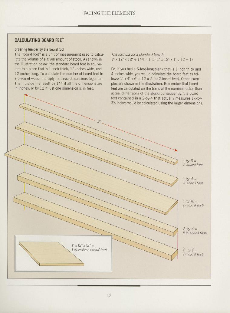
CATCULATING BOARD FEET
Ordering lumber by the board footThe "board foot" is a unit of measurement used to calcu-late the volume of a given amount of stock. As shown inthe illustration below, the standard board foot is equiva-lent to a piece that is 1 inch thick, 12 inches wide, and12 inches long. To calculate the number of board feet ina piece of wood, multiply its three dimensions together.Then, divide the result by I44 i f al l the dimensions arein inches, or by 12 i f just one dimension is in feet.
The formula for a standard board:I " x 12" x 12" + I44 = I (o r 1 " x 12" x I ' - 12 = I )
So, if you had a 6-foot-long plank that is 1 inch thick and4 inches wide, you would calculaie the board feet as fol-lows: 1" x 4" x 6' = 12 = 2 (or 2 board feet). Other exam-ples are shown in the illustration. Remember that boardfeet are calculated on the basis of the nominal rather thanactual dimensions of the stock; consequently, the boardfeet contained in a 2-by-4 that actual ly measures 1%-by-3% inches would be calculated using the larger dimensions.
A l
1-by-3 =2 board feet
1-by'6 =4 board feet
1-by-12 =B board feet
2-by-4 =5 % board feeL
2'by-6 =B board feet
1 " x 1 2 " x 1 2 " =1 Etandard board foof,
t 7
IOINERY AND HARDWARE
I oinery presents unique challenges to
J the outdoor furniture maker. Manyof the standard ioints used for indoorfurniture are incapable of withstandingthe abuses wrought by weather. Theblind mortise-and-tenon joint, for exam-ple, is normally an excellent choice forjoining chair rails and legs, but it doesnot fare well outdoors. Water canbecome trapped in the mortise, caus-ing the joint to swell and leading towood decay. A variation on the samejoint, the through mortise-and-tenon(page 19), solves that problem by allow-ing water to drain out. Cutting angledshoulders helps prevent water frombecoming trapped. Lap joints and rab-bet joints also work well. For extra pro-tection against water, you can coat themating surfaces of joints with a preser-vative such as pine tar or an adhesivecaulking compound.
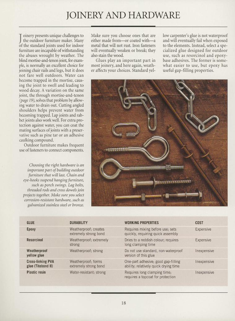
Outdoor furniture makes frequentuse of fasteners to connect components.
Choosingthe righthardware is animportant part of building outdoorfurniture that will last. Chain and
eye-hooks suspend hanging furniture,such as porch swings. Lag bolts,
threaded rods and cross dowels joinprojects together. Make sure you selectcorrosion-resistant hardware, such as
galvanized stainless steel or bronze.
GtUE
Epoxy
Resorcinol
Weatherproofyellow glue
Gross-linking PVAglue (Titebond ll)
Plastic resin
Make sure you choose ones that areeither made from-or coated with-ametal that will not rust. Iron fastenerswill eventually weaken or break; theyalso stain the wood.
Glues play an important part inmost joinery, and here again, weath-er affects your choices. Standard yel-
low carpenter's glue is not waterproofand will eventually fail when exposedto the elements. Instead, select a spe-cialized glue designed for outdooruse, such as resorcinol and epoxy-base adhesives. The former is some-what easier to use, but epoxy hasuseful gap-f i l l in g propert ies.
DURABITITY
Weatherproof; createsextremely strong bond
Weatherproof ; extremelystrong
Weatherproof; strong
Weatherproof; formsextremely strong bond
Water-resistant; strong
WORKING PROPERTIES
Requires mixing before use; setsquickly, requir ing quick assembly
Dries to a reddish colour; requireslong clamping t ime
Do not use standard, non-waterproofversion of this glue
0ne-part adhesive; good gap-fil l ingability; relatively quick drying time
Requires long clamping t ime;requires a topcoat for protection
cosTExpensive
Expensive
I nexpensive
I nexpensive
I nexpensive
IItIIItIIIIIItIIIIIIIIIttIIIIttI
1 8
FACING THE ELEMENTS
ItIIIIItIIIIIIIIIIIIIIIIIIIIIItI
FINISHING
f he finish on any project has two pur-I poses: to beautifr the wood and pro-
tect it. However, if you have built yourfurniture from rot-resistant and stablewood, you may choose to leave the woodunfinished. This cuts down substantial-ly on maintenance, because once a finishii applied, it must be renewed periodi-cally. Still, for the less decay-resistantwoods, finishing is your best choice toprotect the furniture from the elementsand to keep insects atbay. Also, somewoods with little figure may look bettercoveredwith paint or a stain. A pigment-ed topcoat will also conceal any mis-matched grain.
The most common finishing choic-es are penetrating oils, varnishes, andpaint. Spar varnish requires that the firstcoat be thinned. with undiluted varnishfor the subsequent coats. Other finishes,especially paints, need a sealer first, fol-lowed by primer, then the finishing coats.
Water is not the only threat to out-door furniture. Sunlight can damagewood by destroying the lignin in thewood, which fortifies the cell walls. Ifyou want to shield the wood complete-lyfrom the sun, use paint. Generally, thehigher the gloss, the better the protec-tion, since the gloss will serve to reflectthe sun's rays. Some finishes, such asspar varnish, contain ultraviolet (UV)filters, which help shield the furniturefrom the sun's harmful radiation. Formaximum W protection, apply four orfive coats.
Finally, do not expect a finish to sal-vage a poor construction. While thereare very expensive finishes available, suchas catalyzed linear polyurethane, thatwill protect wood from virtually any-thing, including submerging it in water,the best way to ensure that your piece offurniture lasts is to start with the rightjoinery and glues.
IIIIIItttIIttIIttIItIIIIIIIIIIII
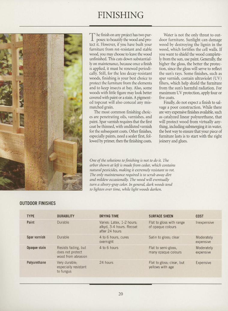
One of the solutions to finishingis not to do it. Thearbor shown at left is made from cedar, which containsnatural pesticides, making it extremely resistant to rot.The only maintenance required is to scrub away dirtand mildew occasionally. The wood will eventuallyturn a silvery-gray color. In general, darkwoods tendto lighten over time, while light woods darken.
OUTDOOR FINISHES
TYPEPaint
Spar varnlsh
0paque stain
Polyurethane
DURABITITY
Durable
Durable
Resists fading, butdoes not protectwood from abrasion
Very durable;especially resistantto fungus
DRYING TIME
Varies: Latex, 1-2 hours;alkyd, 3-4 hours. Recoatafter 24 hours
4 to 6 hours, curesovernight
4 to 6 hours
24 hours
SURFAGE SHEEN
Flat to gloss with rangeof opaque colours
Satin to gloss; clear
Flat to semi-gloss,many opaque corours
Flat to gloss; clear, butyellows with age
cosTI nexpensive
Moderatelyexpensive
Moderatelyexpensive
Expensive
20
FACING THE ELEMENTS
I
tI
tI
tI
I
I
I
t
I
I
I
I
I
I
I
I
I
I
I
I
I
T
tT
I
I
I
I
I
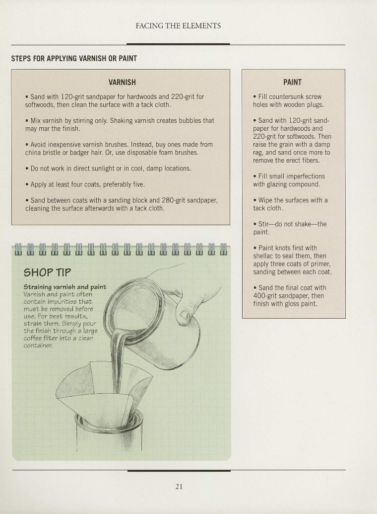
STEPS FOR APPLYING VARNISH (lR PAINT
VARNISH
o Sand with 12O-grit sandpaper for hardwoods and 220-grit forsoftwoods, then clean the surface with a tack cloth,
o Mix varnish by st irr ing only, Shaking varnish creates bubbles thatmay mar the f in ish.
o Avoid inexpensive varnish brushes. Instead, buy ones made fromchina brist le or badger hair. 0r, use disposable foam brushes.
o Do not work in direct sunlight or in cool, damp locations.
. Apply at least four coats, preferably five.
o Sand between coats with a sanding block and 280-grit sandpaper,cleaning the surface afterwards with a tack cloth.
Illl fin fill tjll illt tlll llll ljlt lll1 jitl fiti llll lllt illr itlj llll filr fill1HO? TI?St raining varnish and p aintVarnish and oaint oftenc o nN ain imp ur i t i e o lh atmuel be removed beforeuse. For besl resultrs,sNrain them. Simply pourlhe f in ish Nhrou4h a larqecoffee filNer into a cleanconlainer,
PAINT
o Fil l countersunk screwholes with wooden plugs.
o Sand with 120-grit sand-paper for hardwoods and220-grit for softwoods. Thenra ise the gra in wi th a damprag, and sand once more toremove the erect f ibers.
r Fi l l small imperfectionswi th g laz ing compound.
. Wipe the surfaces with atack cloth.
o Stir-do not shake-thepai nt.
o Paint knots f irst withshel lac to seal them, thenapply three coats of primer,sanding between each coat.
. Sand the f inal coat with400-grit sandpaper, thenf in ish wi th g loss paint .
_ . )
2 l
- ' t - ] , j $ € r
gtt*"'i*i)-
'it
w%d
hF
**
I
I
I
I
tI
I
T
I
I
I
I
I
t
tI
I
I
I
I
I
I
I
I
I
I
I
I
utdoor furniture must bedesignedto rough it, andthe
Adirondack chair, chaise lounge,and curved chair featured in thischapter are all up to the task. Inmany parts of the country withharsh winters, the appearance ofoutdoor chairs marks the return ofpleasant weather. Carted out of thegarage or basement on the first sun-ny day ofspring, given a quick dust-ing off, and then left exposed tothe elements, they must withstandrough use, indeed, until they arereturned to shelter after the firstfrost. Such treatment places a par-ticular set of demands on the join-ery. The blind mortise-and-tenon,for example, which is normally an
CHAIRS
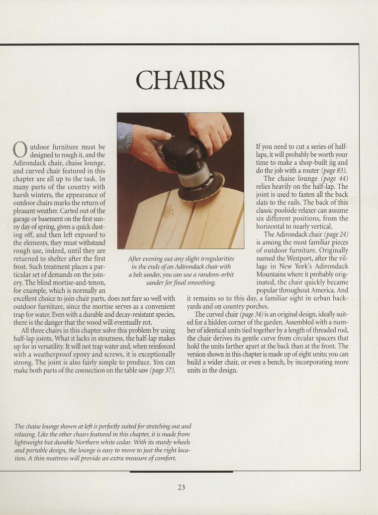
After evening out any slight irregularitiesin the ends of anAdirondackchairwith
abelt sander, you can use a random-orbitsander for final smoothing.
If you need to cut a series of half-laps, it will probably be worth yourtime to make a shop-built jig anddo the job with a router (page 83).
The chaise lounge (page 44)relies heavily on the half-lap. Theioint is used to fasten all the backslats to the rails. The back of thisclassic poolside relaxer can assumesix different positions, from thehorizontal to nearly vertical.
The Adirondack chair (page 2a)is among the most familiar piecesof outdoor furniture. Originallynamed the Westport, after the vil-lage in New York's AdirondackMountains where it probably orig-inated, the chair quickly becamepopular throughout America. And
excellent choice to join chair parts, does not fare so well withoutdoor furniture, since the mortise serves as a convenienttrap for water. Even with a durable and decay-resistant species,there is the danger that the wood will eventually rot.
All three chairs in this chapter solve this problem by usinghalfJap joints. What it lacks in stoutness, the half-lap makesup for in versatility. It will not trap water and, when reinforcedwith a weatherproof epory and screws, it is exceptionallystrong. The joint is also fairly simple to produce. You canmake both parts of the connection on the table saw (page 37).
it remains so to this day, a familiar sight in urban back-yards and on country porches.
The curved chair (page 34) is an original design, ideally suit-ed for a hidden corner of the garden. Assembled with a num-ber ofidentical units tied together by a length ofthreaded rod,the chair derives its gentle curve from circular spacers thathold the units farther apart at the back than at the front. Theversion shown in this chapter is made up of eight units; you canbuild a wider chair, or even a bench, by incorporating moreunits in the design.
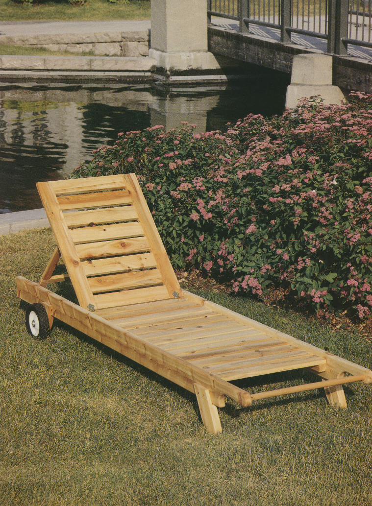
The chaise lounge shown at left is perfealy suited for stretching out andrelaxing. Like the other chairs featured in this chapter, it is made fromlightweight but durable Northern white cedar. With its sturdy wheelsand portable design, the lounge is easy to move to just the right loca-tion. A thin mattress will provide an extra measure of comfort.
II
23
ANATOMY OF AN ADIRONDACK CHAIRI
I
f here are few pieces of outdoor fi.rr-I nirure more invitine than an Adiron-
dack chair. Its reclinin"g seat and tiltedbackest beckon the user to sink into the
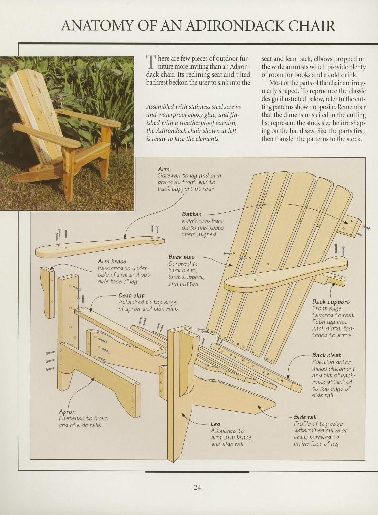
Assembled with stainless steel screwsand waterproof epoxy glue, and fin-ished with a weatherproof varnish,the Adirondack chair shown at leftis ready to face the elements.
seat and lean back, elbows propped onthe wide armrests which provide plentyofroom for books and a cold drink.
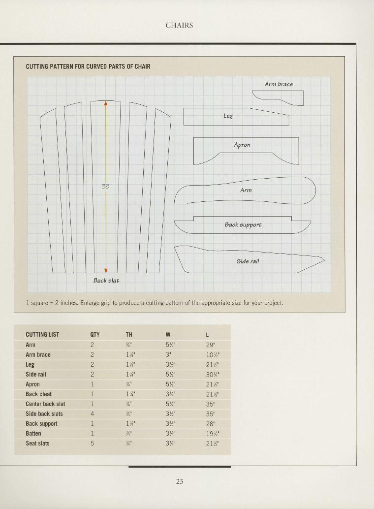
Most of the parts of the chair are irreg-ularly shaped. To reproduce the classicdesign illustrated below, refer to the cut-ting patterns shown opposite. Rememberthat the dimensions cited in the cuttinslist represent the stock size before shapling on the band saw. Size the parts first,then transfer the patterns to the stock.
tI
I
I
tI
I
I
I
I
I
I
tI
I
I
I
I
I
I
T
I
I
I
I
I
. r r \
\ . \ , '
ArmScrewed to leg and armbrace aL front and to
EattenKeinforcea backelata and keepethem ali7ned
Back alatArm braaeFaatened to under-aide of arm and out-oide face of leq
)crewed toback cleat,bacK eupport,and batten
Seat elat'Attached to top ed4eof apron and aide raile
Eack aupportFront edgetapered to reatfluah a4ainotback alata; faa-tened to arma
Back aleatFoaition deter-minee placement.and tilt of back-reot: attachedto top edqe ofeide rail
f,f{f
s@
o@
o@
ApronFastened to front.end of aide raila Leg
Attached toarm, arm brace,and eide rail
5ide railTrofile of top edqedeterminea curve ofaeat; acrewed toinaide face of leq
T
I
I
I CHAIRS
I
I
I
I
T
ttI
I
I
tI
I
I
I
I
tI
I
I
I
tI
T
T
I
CUTTING LIST
Arm
Arm brace
Leg
Side rai l
Apron
Back cleat
Center back slat
Side back slats
Back support
Batten
Seat slats
8TYZ
z
z
Z
1
1
1
4
1
15
TH
%'
IYo'
IY4'
LYo'
%'
IY4'
%'
%'
lr/4'
3/qu
%u
W5%',? x
?r/^n
5v,'R1/^il
?r / " t
5Y2'
?v" ,
3v,'3Y4'
3Yo'
t29',I0Yz'2rv, '30%'
2I%',
2I%',
35 '
35"
28',
19y,',
2 t % '
CUfiING PATTERN FOR CURVED PARTS OF CHAIR
1 square = 2 inches. Enlarge grid to produce a cutting pattern of the appropriate size for your project.
Baak alat
25
BUILDING AN ADIRONDACK CHAIR
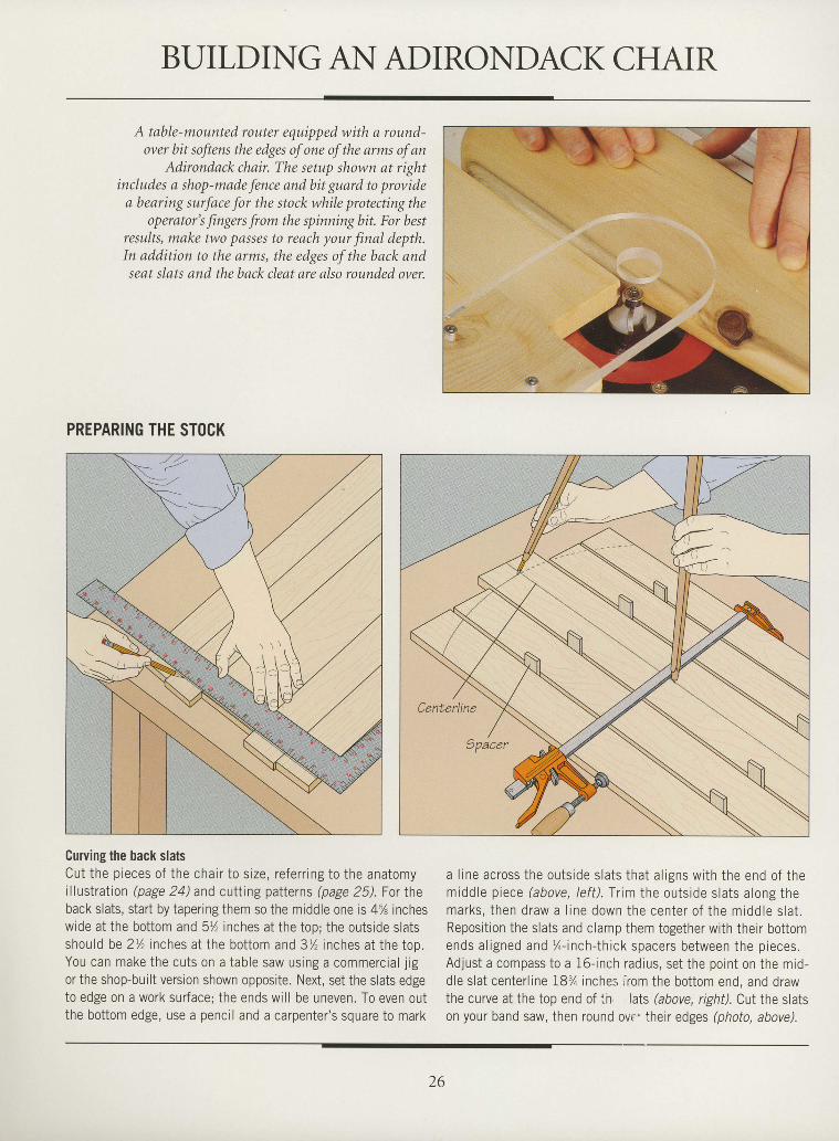
A tttble-mounted router equipped with n rowtd-over bit soJiens the edges of one of the arms of an
Adirondack chnir. The senrp shown at rightincludes a shop-made fence and bit guard to providea beorirrg xrrfnce for the stock wl'rile protecting the
operator's fingers front the spinningbit. For bestresuks, rrrake two passes to reach yow"finnl clepth.Irt ctdclitiort to the arms, the edges of the back andsent slsts and the back cleat are trlso rounded over.
PREPARING THE STOCK
Curving the back slatsCu t t he p ieces o f t he cha i r t o s i ze , r e fe r r i ng t o t he ana tomyil lustration (page 24) and cutting patterns (page 25). For theback s lats , s tar t by taper ing them so the middle one is 4% incheswide at the bot tom and 5Y, inches at the top; the outs ide s latsshould be 2Y' inches at the bot tom and 3/ , inches at the too.You can make the cuts on a table saw using a commercia l j igor the shop-built version shown opposite. Next, set the slats edgeto edge on a work sur face; the ends wi l l be uneven. To even outthe bot tom edge, use a penci l and a carpenter 's square to mark
a l i ne ac ross t he ou ts ide s la t s t ha t a l i gns w i th t he end o f t hemiddle n iee.e (ahove lef t ) . f r im the outs ide s lats a lons themarks , t hen d raw a l i ne down the cen te r o f t he m idd le s l a t .Reposi t ion the s lats and c lamp them together wi th thei r bot tomends a l i gned and %- inch - th i ck space rs be tween the p ieces .Adjust a compass to a i6- inch radius, set the point on the mid-d le s lat center l ine 18% inches ' r .om the bot tom end, and drawthe crrrve at the ton end of ln lats (above. rishf). CuI the slats' u | J
\ u U v ' w . ' | 6 ' l L /
on your band saw, then round ovt therr edges (photo, above).
I
I
I
T
I
I
I
I
I
I
I
I
I
tI
I
I
I
I
I
I
I
T
I
I
I
I
t
I
I
I
I
':rya.
\'.
i&
€
26
CHAIRS
tI
I
tI
I
I
I
I
I
I
I
I
tI
I
I
I
I
rI
I
tI
I
I
I
I
rI
I
I
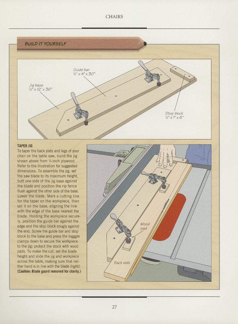
TAPER JIGTo taper the back slats and legs of yourcha i r on the tab le saw, bu i ld the j igshown above from %-inch plywood.Refer to the illustration for suggesteddimensions. To assemble the j ig, setthe saw blade to its maximum height,butt one side of the jig base againstthe blade and posit ion the r ip fenceflush against the other side of the base.Lower the blade. Mark a cutt ing l inefor the taper on the workpiece, thenset i t on the base, a l ign ing the l inewith the edge of the base nearest theblade. Holding the workpiece secure-ly, posi t ion the guide bar against theedge and the stop block snugly againstthe end. Screw the guide bar and stopblock to the base and press the togggleclamps down to secure the workpieceto the jig; protect the stock with woodpads. To make the cut, set the bladeheight and sl ide the j ig and workpieceacross the table, making sure that nei-ther hand is in line with the blade (righil.(Caution: Blade guard removed for clarig.)
lI
Iilirittii
iltilxlil
x$
" . , , i
27
CHAIRS
ASSEMBLING THE CHAIR
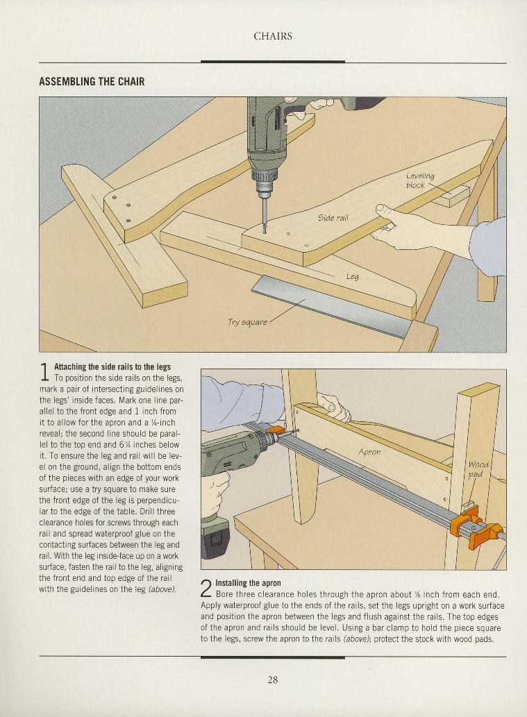
1 Attaching the side rails to the legsI To position the side rails on the legs,mark a pair of intersect ing guidel ines onthe legs' inside faces. Mark one l ine par-al lel to the front edge and 1 inch fromi t to a l low fo r the apron and a %- inchreveal; the second l ine should be paral-lel to the top end and 63/o inches belowit . To ensure the leg and rai l wi l l be lev-el on the ground, al ign the bottom endsof the pieces with an edge of your worksurface; use a try square to make surethe front edge of the leg is perpendicu-lar to the edge of the table. Dri l l threeclearance holes for screws through eachrai l and spread waterproof glue on thecontacting surfaces between the leg andrail. With the leg inside-face up on a worksurface, fasten the rail to the leg, aligningthe front end and top edge of the rai lwi th the guidel ines on the leg hbove).
I
I
I
I
I
I
I
I
I
I
I
I
I
I
I
I
I
I
I
I
I
I
I
I
T
I
I
I
I
tI
I
O Installing the apronL Bore th ree c learance ho les th rough the apron abou l% inch f rom each end.Apply waterproof glue to the ends of the rai ls, set the legs upright on a work surfaceand posit ion the apron between the legs and f lush against the rai ls. The top edgesof the apron and ra i l s shou ld be leve l . Us ing a bar c lamp to ho ld the p iece squareto the legs, screw the apron to the rails (abovd; protect the stock with wood pads.
Try equare
2B
CHAIRS
I
I
I
tI
I
t
I
I
I
I
I
I
I
I
I
tI
I
I
I
I
I
I
t
I
I
I
tI
I
t
I t l r l i i i l l i i l l i l i l i l i i l i r l l l r i l r l l l l l l l l l l { i l l l l l l l i l l i l l l i l l l i l r r i { r r r iilJ t$ i$ u r$ t$ ill ill l$ $ ilj ru ili i$ fli {$ l$ ll.l
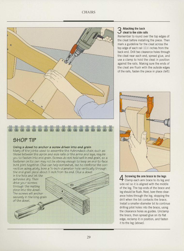
5HO? TI?Uoing a dowel to anchor a earew driven into end grainMany of Nhe jointe ueed to assemble the Adirondack chair, such asthose belween Nhe aVron and eide rails or lhe arms and lego, requireyou Lo f aslen int o end qrain. Screws do noN hold well in end qrain, oo afastener on its own may noL be oLrong enough Lo keep an end-Io-facebuLf, jo inLLoqeNher. Glue can helV somewhaL,butLo reinforcelhe con'n e cLi o n a d e qu ately, b o r e a'/e - i n ch - di a m et e r h ol e v e rti c ally th r o u qhLhe end arain oiece abouL /zinch from its end. Olue a dowelin lhe ho le and le l lheadhesive dry,Thendflve your Screw7throughlhe mal inqn i a r a i n + a + l ^ . ) ^ , ^ , - l
The ecrews will anchoroecurely in the lonq grainof lhe dowel.
1 Attachins the backr-J cleat to the side railsRemember to round over the top edges ofthe c leat before insta l l ing the p iece. Thenmark a guidel ine for the c leat across thetop edge of each ra i l I I% inches f rom theback end. Dr i l l two c learance holes throughthe c leat near each end, spread g lue, anduse a c l amp to ho ld t he c lea t i n pos i t i onagainst the ra i ls . Making sure the ends ofthe c leat are f lush wrth the outs ide edgesof the rails, fasten the piece in place (left).
,{ Screwing the arm brace to the legs-T Clamp each arm brace to i ts leg ands ide ra i l so i t i s a l i gned w i th t he m idd leof the lep The inn ends of the brace andleg should be flush. Next, bore three clear-ance holes through the leg, s topping thed r i l l when the b i t con tac t s t he b race .Insta l l a smal ler-d iameter b i t to cont inued r i l l i ng p i l o t ho les i n to t he b race , us ingthe c learance holes as guides. Unclampthe brace. then snread s lue on i ts f la tedge, rec lamp i t in posi t ion, and fastenit to the leg (above).
29
CHAIRS
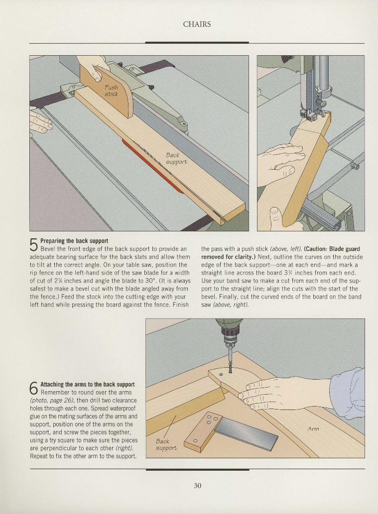
f , Prepar ing the back supportr - . / Bevel the f ront edge of the back support to prov ide anadequa te bea r i ng su r face fo r t he back s la t s and a l l ow themto t i l t a t t he co r rec t ans le On vo r r r t ah le saw oos i t i on t her i n f ence on the l e f t - hand s rde o f t he saw b lade fo r a w id tho f cu t o f 2% inches and ang le t he b lade to 30 ' . ( l t i s a lwayssafest to make a bevel cut wi th the b lade angled away f romthe fence . ) Feed the s tock i n to t he cu t t i ng edge w i th you rl e f t hand wh i l e p ress ing the boa rd aga ins t t he f ence . F in i sh
the pass with a push stick (above, /eff). (Caution: Blade guardremoved fo r c l a r i t y , ) Nex t , ou t l i ne t he cu rves on the ou ts idee d s e o f t h e b a c k s r r n n o r t o n e a t e a c h e n d a n d m a r k as t r a i g h t l i n e a c r o s s t h e b o a r d 3 7 i n c h e s f r o m e a c h e n d .Use you r band saw to make a cu t f r om each end o f t he sup -po r t t o t he s t ra igh t l i ne ; a l i gn t he cu ts w i i h t he s ta r t o f t hebeve l . F ina l l y , cu t t he cu rved ends o f t he boa rd on the bandsaw (above, right).
tI
I
I
I
I
I
I
I
I
I
tI
I
I
I
I
I
I
I
I
I
I
I
I
I
I
I
I
I
I
I
f Attaching the arms to the back supporth
L , f Remember t o round ove r t he a rms(nhofo. nape 26) . then dr i l l two c learanceholes through each one. Spread waterproofglue on the mating surfaces of the arms andsupport , posi t ion one of the arms on thesupport , and screw the p ieces together ,us ing a t ry square to make sure the p iecesare perpendicular to each other ( r igh i l .
Repeat to f ix the other arm to the support .
30
CHAIRS
rI
ttI
I
I
I
I
I
I
I
I
I
tI
tI
I
I
I
I
I
I
I
ttI
I
I
I
I
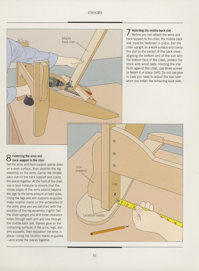
I Instal l ing the middle back slat/ Before vou can attach the arms andback support to the chair , the middle backs la t must be fas tened in p lace . Set thechair upr ight on a work surface and clampthe s la t to the center o f the back c lea t ,a l ign ing the bo t tom end o f the s la t w i ththe bottom face of the cleat; protect thes tock w i th wood pads . Ho ld ing the s la tf lush against the cleat, use three screwsto fasten it in place (left), Do not use gluein case you need to adjust the slat laterwhen you instal l the remaining back slats.
Fastening the arms andback support to the chair
Set the arms and back support upside downon a work surface, then posit ion the legassembly on the arms. Center the middleback slat on the back support and clampthe pieces together. At the front of the chair,use a tape measure to ensure that theinside edges of the arms extend beyondthe legs by the same amount on both sides.Using the legs and arm supports as guides,make locat ion marks on the undersides ofthe arms once you are sat isf ied with theposition of the leg assembly (righil. Setthe chair upr ight and dr i l l three clearanceholes through each arm and one throughthe middle back slat . Spread glue on thecontact ing surfaces of the arms, legs, andarm supports, then reposit ion the arms inplace-using the locat ion marks as guides-and screw the preces together.
Locattoh markE
3 l
CHAIRS
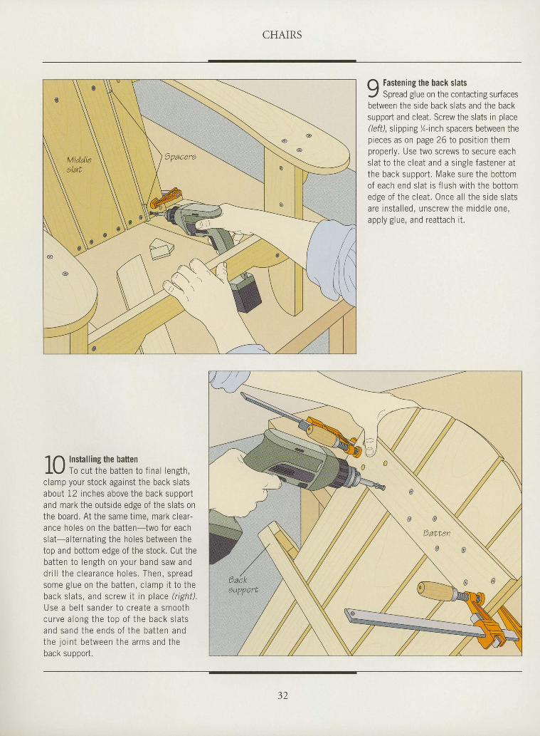
Q Fastenin9 the back slats
J Spread glue on the contacting surfacesbetween the side back slats and the backsupport and cleat. Screw the slats in place(/eff), slipping %-inch spacers between thepieces as on page 26 to posit ion themproperly. Use two screws to secure eachslat to ihe cleat and a single fastener atthe back support . Make sure the bottomof each end slat is f lush with the bottomedge of the cleat. Once al l the side slatsare instal led, unscrew the middle one,apply glue, and reattach i t .
I
I
I
I
I
I
I
I
I
I
I
I
I
I
I
I
I
I
I
I
I
I
I
I
I
tI
I
I
I
I
I
1 n Installing the battenI\,/ To cut the batten to f inal length,clamp your stock against the back slatsabout 12 inches above the back suooortand mark the outside edge of the slats onthe board. At the same t ime, mark clear-ance holes on the batten-two for eachslat-al ternat ing the holes between thetop and bottom edge of the stock. Cut thebatten to length on your band saw anddr i l l the c learance ho les . Then, spreadsome g lue on the ba t ten , c lamp i t to theback slats, and screw i t in place (r ight)Use a be l t sander to c rea te a smoothcurve a long the top o f the back s la tsand sand the ends o f the ba t ten andthe jo in t be tween the arms and theback su pport .
J./.
CHAIRS
I
tI
I
I
I
I
I
I
I
tI
I
I
I
I
I
I
tI
I
I
I
I
I
I
I
I
I
I
I
I
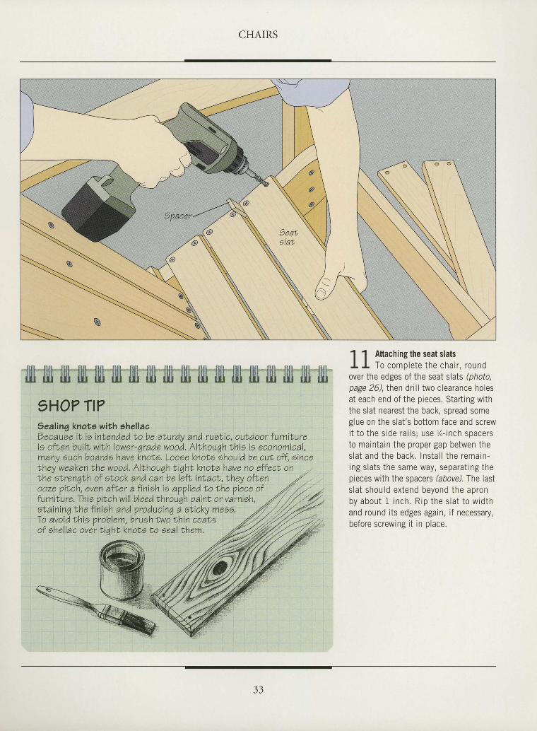
llit lltl lill fiil fifi ljll fill ltl llu fiil tljl illt lljl fiil ffi illr llr ilt1HO? Tt?Sealinq knots with ehellacOecause it is intended to be oLurdy and ruslic, ouldoor furnilureis often bui l t with lower-qrade wood. Althouqh thio is economical,many euch boards have knoLs, Loose knols should be cul off, sincelhey weaken the wood. Allhouqh tiqht knote have no effecl onLhe st renqlh of ebock and canbelef t , in lact , ,Lhey ofLenooze piLch, even afLer a finish io applied t o the Viece offurnilure.lhie pilch will bleed throuqh paint, or varnish,otaining the f in ish and.Vroducinq a ot icky meoo. / 'To avoid this oroblem. brush lwo thin coaloof shel lac over t iaht knots Lo seal lhem.
1 1 Attaching the seat slatsI I To comple te the cha i r , round
n v o r t h e p d o e s n f t h e c e ; t ^ t ^ t ^ / ^ L ^ t ^u v L r ! r r L U U E U J v r L r r u J U d L 5 l d L 5 l p r l u t U ,
page 2O, then dr i l l two c learance holesat each end of the p ieces. Star t ing wi ththe s lat nearest the back, spread someglue on the s lat 's bot tom face and screwi t t o t he s i de ra i l s ; use l - i nch space rsto mainta in the proper gap betwen thes la t and the back . l ns ta l l t he rema in -i ng s l a t s t he same way , sepa ra t i ng t hepieces with the spacers (above). The lasts l a t shou ld ex tend beyond the ap ronb y a b o u t 1 i n c h . R i p t h e s l a t t o w i d t hand round i ts edges again, i f necessary,before screwing i t in p lace.
ANATOMY OF A CURVED CHAIR
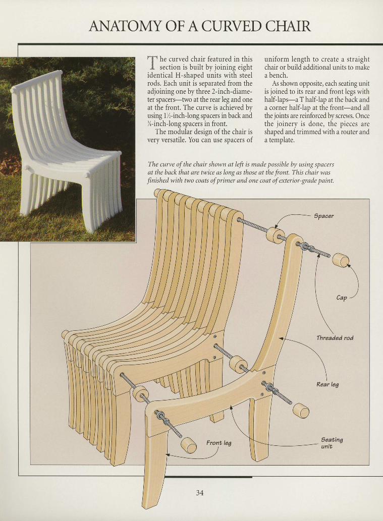
tl- h. curved chair featured in thisI . sect ion is bui l t by joining eight
identical H-shaped units with steelrods. Each unit is separated from theadjoining one by three 2-inch-diame-ter spacers-two at the rear leg and oneat the front. The curve is achieved byusing 1%-inch-long spacers in back and%-inch-long spacers in front.
The modular design of the chair isvery versatile. You can use spacers of
uniform length to create a straightchair or build additional units to makea bench.
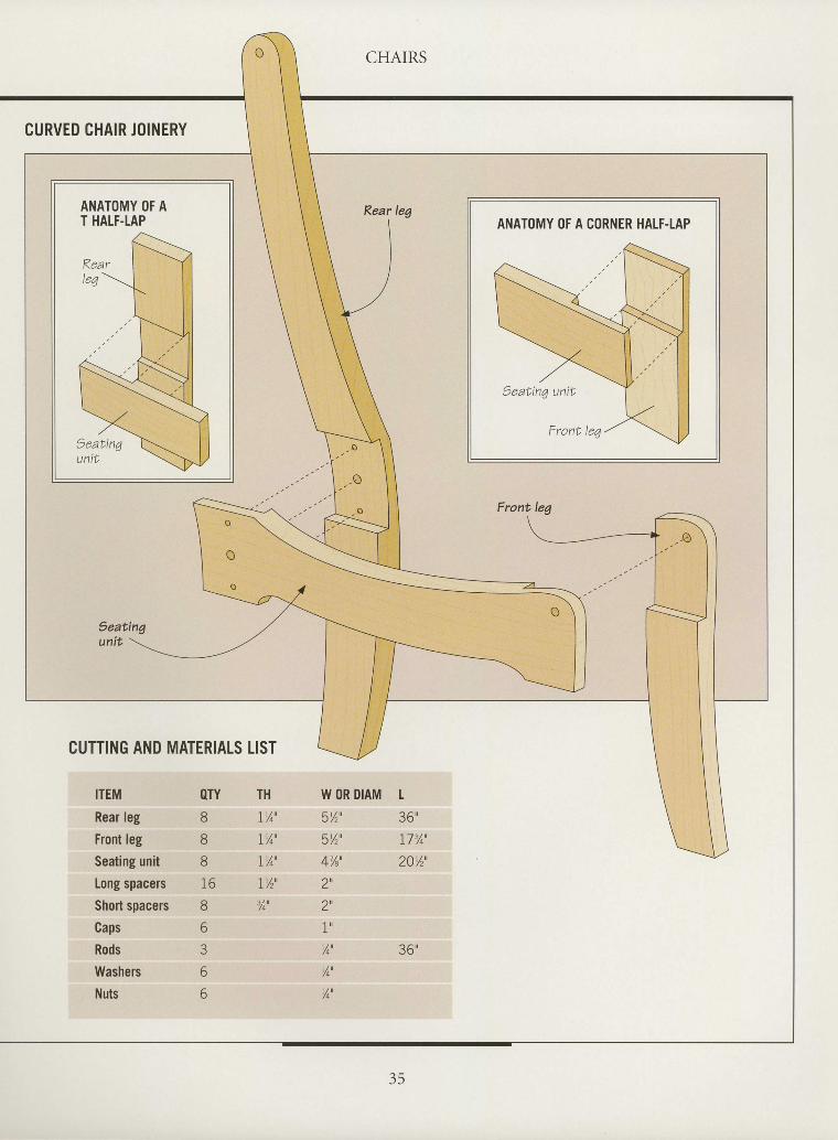
As shown opposite, each seating unitis joined to its rear and front legs withhalf-laps-a T half-lap at the back anda corner half-lao at the front-and allthe joints are reinforced by screws. Oncethe joinery is done, the pieces areshaoed and trimmed with a router anda temnlate.
I
I
I
I
I
I
I
I
I
I
I
I
I
I
I
I
I
I
I
I
I
I
I
I
I
I
The curye of the chair shown at left is made possible by using spacersat the back that are twice as long as those at the front. This chair wasfinished with two coats of primer and one coat of exterior-grade paint.
t cuRvED cHArR JoTNERY
I
I
I
I
I
I
I
I
I
I
I
I
I
I
tI
I
l,
I
I
I
I
I
I
I
CUTTING AND MATERIATS LIST
CHAIRS
W OR DIAM L
5Yr' 36'
sYr ' I7%'
4%', 20yr'
a i lZ
1 u
Y4u 36'
%'
Y^'
ITEM OTY
Rear leg 8
Front leg 8
Seating unit 8
Long spacers 16
Short spacers 8
Caps 6
Rods 3
Washers 6
Nuts 6
TH
IY^'
I% '
IYo'
IY, '%'
FASHIONING A CURVED CHAIR
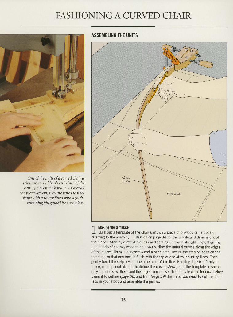
One of the units of a curved chair istrimmed to within about'h inch of thecuttingline on theband saw. Once all
the pieces are cut, they are pared to finalshape with a router fitted with a llush-
trimming bit, guided by a template.
ASSEMBI.ING THE UNITS
1 Making the templateI Mark out a template of the chair units on a piece of plywood or hardboard,referring to the anatomy illustration on page 34 for the profile and dimensions ofthe pieces. Start by drawing the legs and seating unit with straight lines, then usea thin strip of springy wood to help you outline the natural curves along the edgesof the pieces. Using a handscrew and a bar clamp, secure the strip on edge on thetemplate so that one face is flush with the top of one of your cutting lines. Thengently bend the strip toward the other end of the line. Keeping the strip firmly inp lace , runapenc i la long i t todef ine thecurve (above) .Cut the templa te toshapeon your band saw, then sand the edges smooth. Set the template aside for now; beforeusing it to outline (page 38)and trim (page 39Ihe units, you need to cut the half-laps in your stock and assemble the pieces.
I
I
I
I
I
I
I
I
I
I
T
I
I
I
I
I
I
I
I
I
I
il
I
I
I
I
I
I
I
I
I
I
36
CHAIRS
I
I
ttI
tII
I
tI
I
I
tI
I
I
I
I
I
I
I
I
I
I
I
I
I
I
I
tt
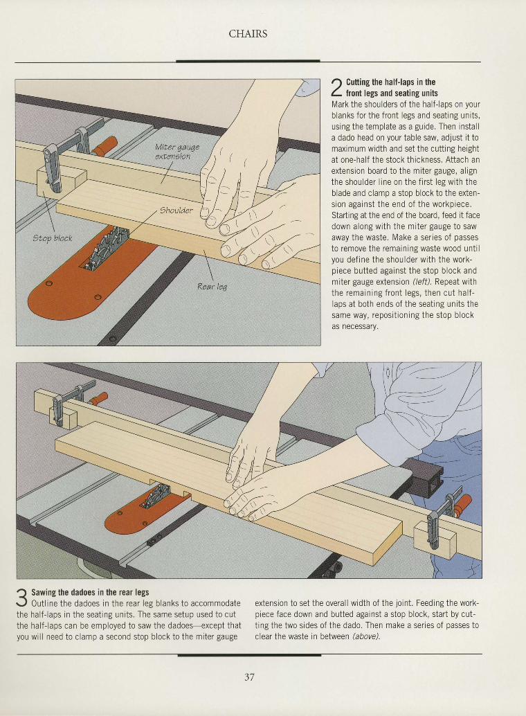
I Sawing the dadoes in the rear legs<
r-J 0ut l ine the dadoes in the rear leg blanks to accommodatethe half- laps in the seat ing units. The same setup used to cutthe half- laps can be employed to saw the dadoes-except thatyou wi l l need to clamp a second stop block to the miter gauge
extension to set the overal l width of the jo int . Feeding the work-piece face down and butted against a stop block, start by cut-t ing the two s ides of the dado. Then make a ser ies of passes toclear the waste in between hbovd.
Miter 4au4eexten9ton
r) Cutting the half-laps in theL tront legs and seating unitsMark the shoulders of the half- laps on yourblanks for the front legs and seat ing units,using the template as a guide. Then instal la dado head on your table saw, adjust it tomaximum width and set the cutt ing heightat one-half the stock thickness. Attach anextension board to the miter gauge, al ignthe shoulder l ine on the f i rst leg with theblade and clamo a stoo block to the exten-sion against the end of the workpiece.Starting at the end of the board, feed it facedown along with the miter gauge to sawaway the waste. Make a ser ies of passesto remove the remaining waste wood unt i lyou def ine the shoulder with the work-piece butted against the stop block andmiter gauge extension (/eil). Repeat withthe remain ing f ron t legs , then cu t ha l f -laps at both ends of the seat ing units thesame way, reposit ioning the stop blockas necessary.
€w
37
CHAIRS
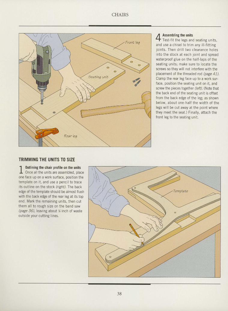
Assembling the unitsTest-f i t the legs and seat ing units,
and use a ch ise l to t r im any i l l - f i t t ingl o i n t s . T h e n d r i l l t w o c l e a r a n c e h o l e sin to the s tock a t each jo in t and spreadwaterproof glue on the half- laps of theseat ing units; make sure to locate thescrews so they will not interfere with theplacement of the threaded rod (page 41).Clamp the rear leg face up to a work sur-face, posi t ion the seat ing unit on i t , andscrew the pieces together (/eff). (Note thatthe back end of the seating unit is offsetfrom the back edge of the leg; as shownbe low, about one-ha l f the w id th o f thelegs wi l l be cut away at the point wherethey meet the seat.) Final ly, at tach thefront leg to the seat ing unit .
I
I
I
I
I
I
I
I
I
I
I
I
I
I
I
I
I
I
I
tI'l
I
I
T
I
,
I
I
I
I
I
TRIMMING THE UNITS TO SIZE
1 0utlining the chair profile on the unitsI Once al l the units are assembled. olaceone face up on a work surface, position thetemplate on i t , and use a penci l to traceits out l ine on the stock (r tght) .Thebackedge of the template should be almost flushwith the back edge of the rear leg at its topend. Mark the remain ing un i ts , then cu tthem al l to rough size on the band saw@age 36), leaving about % inch of wasteoutside your cutt ing l ines.
- - " \\ \ , ,\ \ \
\ - \ - \ )\ - \ _ \ .
, r ' r l l </ / r )
, / , / / l /
(/-/ //''- ' / ' / . 2
CHAIRS
I
tItI
I
tI
I
I
I
I
I
I
I
I
I
I
tI
I
I
I
I
I
I
I
I
I
tII
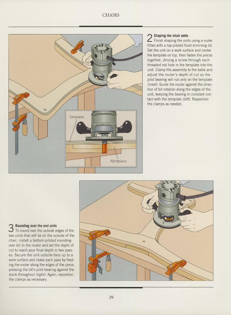
Rounding over the end unitsTo round over the outside edses of the
two uni ts that wi l l be on the outs ide of thechair , insta l l a bot tom-pi lo ted rounding-over b i t in the router and set the deoth ofcut to reach your f ina l depth in two pass-es . Secu re t he un i t ou t s i de - face up to awork surface and make each pass by feed-ing the router along the edges of the piece,pressing the b i t 's p i lo t bear ing against thestock throughout (right). Again, repositionthe clamos as necessarv.
r) Shaping the chair unitsL f tnisn shaping the units using a routerf i t ted with a top-pi loted f lush{r imming bi tSet the unit on a work surface and centerthe template on top, then fasten the piecestogether, dr iv ing a screw through eachthreaded rod hole in the template into theunit . Clamp the assembly to the table andad jus t the rou ter ' s depth o f cu t so thepi lot bearing wi l l rub only on the template(lnsef). Guide the router against the direc-tion of bit rotation along the edges of theunit , keeping the bearing in constant con-tact with the template (/eff). Repositionf h e e l a m n c a c n o o d o d
39
CHAIRS
ASSEMBLING THE CHAIR
I
I
I
I
I
I
I
I
I
ttI
I
I
I
I
I
I
I
I
I
I
I
I
tI
I
tI
tII
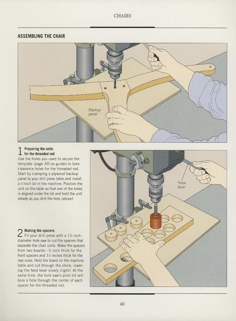
' l Preparing the unitsI for the threaded rodUse the holes you used to secure thetemplate (page 39) as guides to borec learance ho les fo r the th readed rod .Start by clamping a plywood backuppanel to your dr i l l press table and instal la %-inch bi t in the machine. Posit ion theunit on the table so that one of the holesis al igned under the bi t and hold the unitsteady as you drill the hole hbovd.
r) Making the spacersL f i t vour dr i l l oress with a I%-inch-diametei hole saw to cut the spacers thatseparate the chair uni ts. Make the spacersf rom two boards-% inch th ick fo r thefront spacers and I% inches thick for therear ones. Hold the board on the machinetab le and cu t th rough the s tock , lower -rng the feed lever slowly (right). At thesame t ime, the ho le saw 's p i lo t b i t w i l lbore a ho le th rough the center o f eachspacer fo r the th readed rod .
CHAIRS
I
I
I
tI
I
I
I
I
I
I
I
I
I
I
I
I
I
I
I
I
I
I
I
I
I
I
I
tI
tI
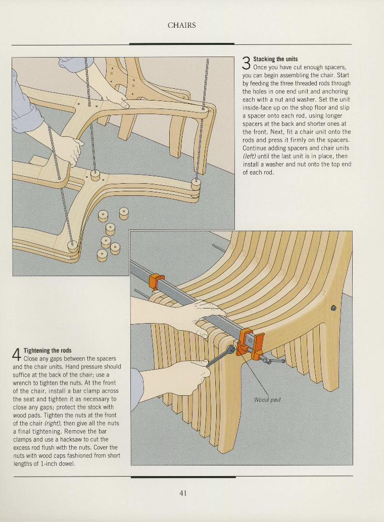
Q Stacking the unitsr-,1 Once you have cut enough spacers,you can begin assembling the chair . Startby feeding the three threaded rods throughthe ho les in one end un i t and anchor ingeach with a nut and washer. Set the unitins ide- face up on the shop f loor and s l ipa spacer on to each rod , us ing longerspacers at the back and shorter ones atthe f ron t . Nex t , f i t a cha i r un i t on to therods and press i t f i rm ly on the spacers .Cont inue add ing spacers and cha i r un i ts(left) until the last unit is in place, theninstal l a washer and nut onto the top endof each rod.
Tightening the rodsClose any gaps between the spacers
and the chair uni ts. Hand oressure shouldsuff ice at the back of the chair ; use awrench to t ighten the nuts. At the fronto f the cha i r , ins ta l l a bar c lamp acrossthe seat and t ighten i t as necessary toclose any gaps; protect the stock withwood pads. Tighten the nuts at the frontof the chair (r ight) , Ihen give al l the nutsa f ina l t igh ten ing . Remove the barclamps and use a hacksaw to cut theexcess rod flush with the nuts. Cover thenuts with wood caps fashioned from shortlensths of 1- inch dowel.
4 l
CHAIRS
INSTALLING ARMS
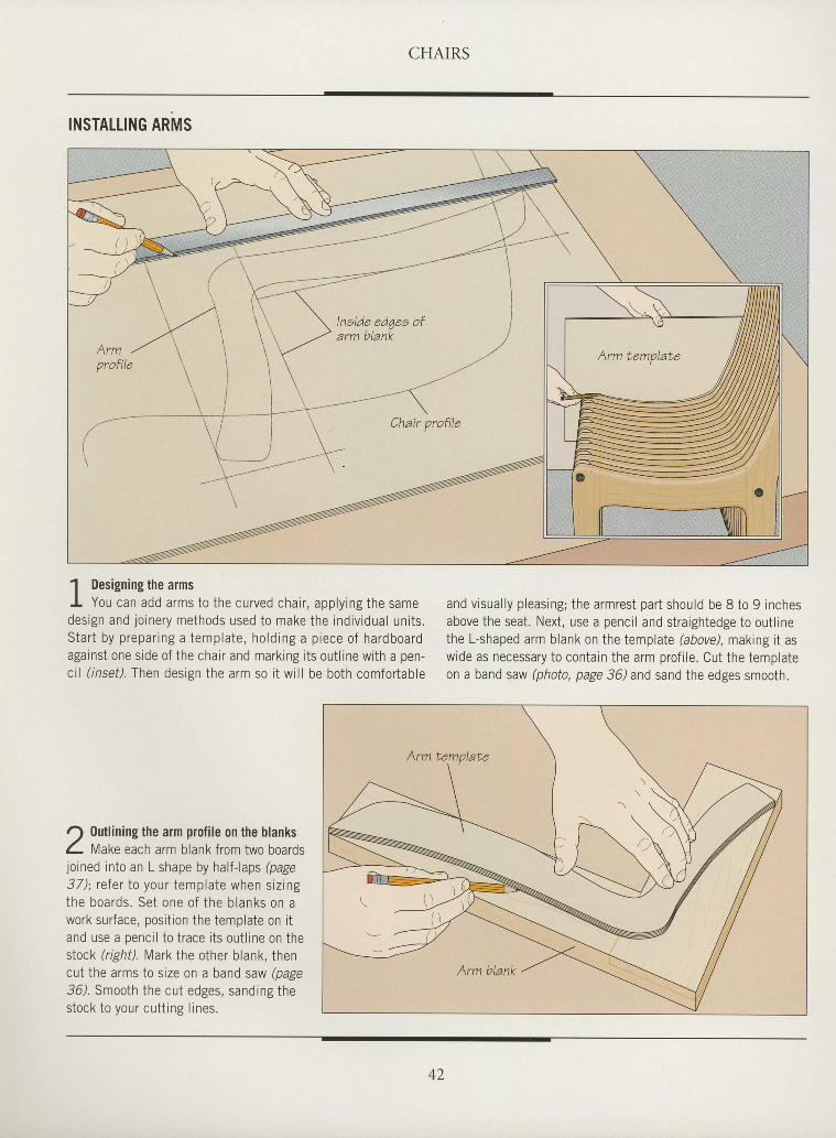
' l Designing the armsI You can add arms to the curved chair , applyingthe samedesign and joinery methods used to make the individual uni ts.S tar t by p repar ing a templa te , ho ld ing a p iece o f hardboardagainst one side of the chair and marking i ts out l ine with a pen-ct l ( insei l . Then design the arm so i t wi l l be both comfortable
and visual ly pleasing; the armrest part should be 8 to 9 inchesabove the seat. Next, use a pencil and straightedge to outlinethe L-shaped arm blank on the templale (abovd, making i t aswide as necessary to contarn the arm prof i le. Cut the templateon a band saw (photo, page 36) and sand the edges smooth.
I
I
I
I
I
I
I
I
I
tII
I
I
I
I
tIIItIIIIItIIIII
lneide ed7ee ofarm blank
r) 0utlining the arm profile on the blanksL flat<e each arm blank from two boardsjoined into an L shape by half-laps (page37) ; re fe r to your templa te when s iz ingthe boards . Set one o f the b lanks on awork surface, posi t ion the template on i tand use a penci l to trace i ts out l ine on theslock (right). Mark the other blank, thencut the arms to size on a band saw (pags36). Smooth the cut edges, sanding thestock to your cutt ing l ines.
42
CHAIRS
I
I
I
ttI
I
I
I
I
I
I
I
I
I
I
I
tIItI
I
I
I
I
I
I
I
I
tI
J Rounding over the edges of the arms<'
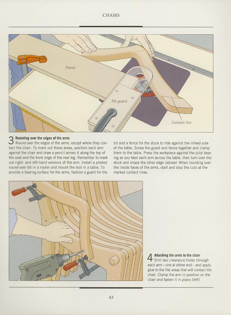
r - ,1 Round over the edges of the arms, except where they con-tac t t he cha i r . To mark ou t t hese a reas , pos i t i on each a rmagainst the chai r and draw a penci l across i t a long the top ofihe seat and the f ront edge of the rear leg. Remember to markou t r i gh t - and l e f t - hand ve rs ions o f t he a rm. I ns ta l l a p i l o tedround -ove r b i t i n a rou te r and moun t t he t oo l i n a t ab le . Toprovide a bear ing sur face for the arms, fashion a guard for the
bit and a fence for the stock to r ide against the infeed sideof the tab le . Screw the guard and fence together and c lampthem to the table. Press the workpiece against the pi lot bear-ing as you feed each arm across the table, then turn over thestock and shape the other edge (above). When rounding overthe inside faces of the arms. start and stoo the cuts at themarked contac t l ines .
f Attaching the arms to the chair- t D r i l l two c lea rance ho les t h rougheach arm one at e i ther end-and applyglue to the f la t areas that wi l l contact thecha i r . C lamp the a rm in pos i t i on on thechair and fasten i t in p lace ( le f t ) .
43
ANATOMY OF A LOUNGE CHAIR
Baakrest eupport etopFreventa backreat eu pportfrom alippinq off rack
Spaaer9upporta themain body elaLa
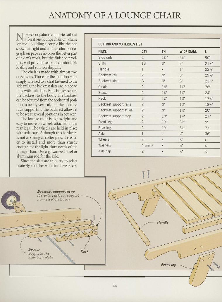
ItT o deck or patio is complete withoutI \ at least one lounse chair or "chaise
longue." Building a couple like the oneshown at right and in the color photo-graph on page22 involves the better partof a day's work, but the finished prod-ucts will provide years of comfortableloafing and sun worshipping.
The chair is made with almost twodozen slats. Those for the main body aresimply screwed to a cleat fastened to theside rails; the backrest slats are joined torails with half-laps. Butt hinges securethe backrest to the body. The backrestcan be adjusted from the horizontal posi-tion to nearly vertical, and the notchedrack supporting the backrest allows itto be set at several positions in between.
The lounge chair is lightweight andeasy to move on wheels attached to therear legs. The wheels are held in placewith axle caps. Although this hardwareis not as strong as cotter pins, it is easi-er to install and more than sturdyenough for the light-duty needs of thelounge chair. Use a galvanized steel oraluminum rod for the axle.
Since the slats are thin, try to selectrelatively knot-free wood for these pieces.
IIIIIIIIIIIII
o PE BE V
IFront leg 5 r
CUTTING AND MATERIALS tIST
PIECE OTY TH W OR DIAM. L
Side ra i l s 2 IY^ ' 4v,' 90"Slats l 3 %'
' t r 21y, ' ,Hand l e X I 22%',Backrest rail a
L %' 3', 29y,',Backrest slats 8 %' 3', 21y, ' ,
Cleats IYo' IYo' 78',Spacer 2 IY4' 1 t / n
I 7 4 24',Rack a
a IYo ' IYo ' 17%',Backrest support rails Z ,/0, IY, ' 19y,',Backrest support sti les 2 %u IY, ' 20'Backrest support stop a
Z IYo' I % ' 2%',Front legs 2 I%' 3v,' 9"Rear legs 2 T%' 3v,' 7 Yo'
Axle 1 X Y,' 36',Wheels a
L X 8u X
Washers 4 ( m i n ) X W' X
Axle cap 2 X v,' X
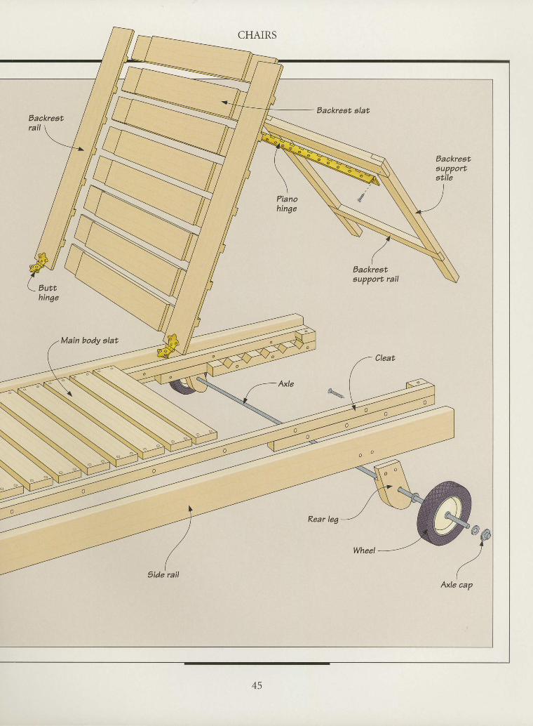
Eaakreat alat
Pianohinge
IIIIIIIIIIIII
Backreatrail
Eackrest'eupportatile
Eackreet'aupport rail
Main body alat
I?ide rail
II
MAKING A LOUNGE CHAIR
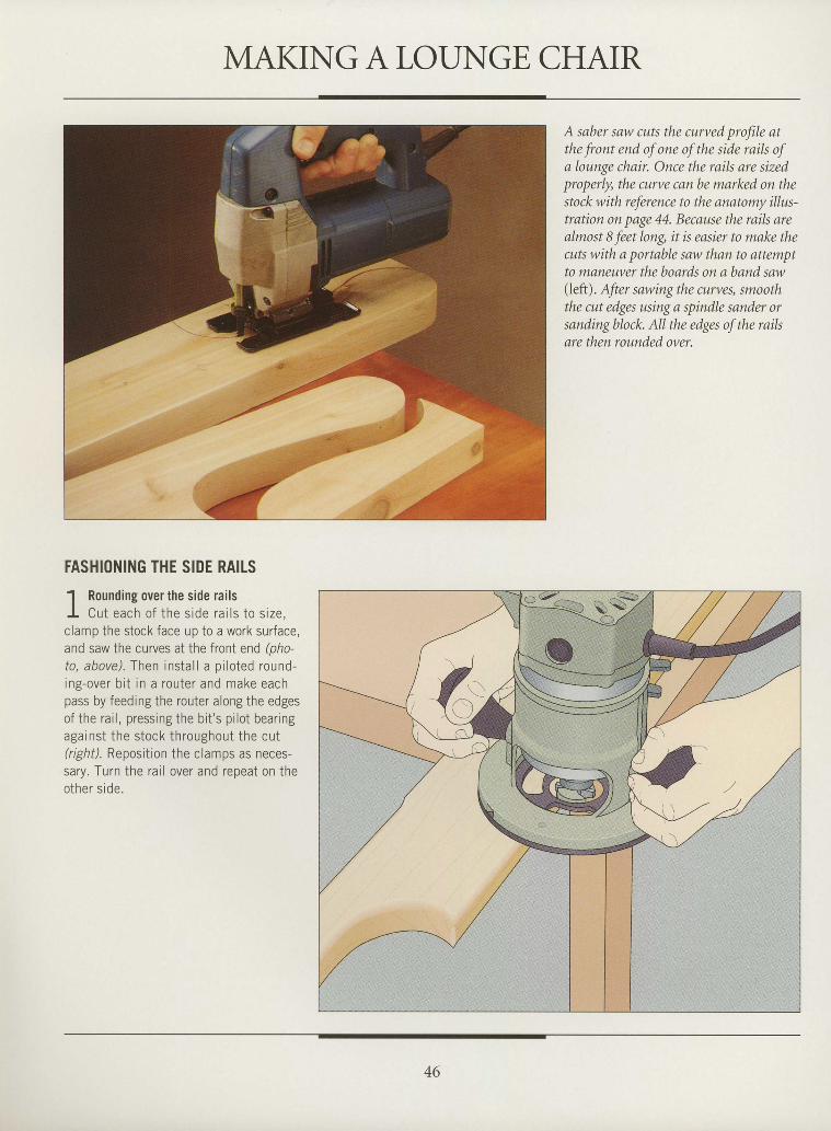
A saber saw cuts the curved profile atthe front end of one of the side rails ofa lounge chair. Once the rails are sizedproperly, the curve can be marked on thestock with reference to the anatomy illus-tration on page 44. Because the rails arealmost 8 feet long, it is easier to make thecuts with a portable saw than to attemptto maneuver the bonrds on a band saw(left). After sawing the cLtrves, smooththe cut edges using a spindle sander orsanding block. All the edges of the raikare then rounded over.
IIIIIItIIIIIIIIIIIItIIIIIIItIIII
FASHIONING THE SIDE RAITS' l Rounding over the side railsI Cut each o f the s ide ra i l s to s ize ,clamp the stock face up to a work surface,and saw the curves at the front end (pho-to, above). Then instal l a pi loted round-ing-over bi t in a router and make eachpass by feeding the router along the edgesof the rai l , pressing the bi t 's pi lot bearingaga ins t the s tock th roughout the cu t(right). Reposition the clamps as neces-sary. Turn the rai l over and repeat on theother side.
40
CHAIRS
I
tItIIIItIIIIIIIIIIIIIIIIIItIIII
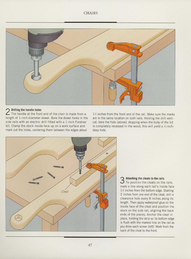
J Dri l l ing the handle holesf- fhe handle at the front end of the chair is made from alength o f 1 - inch-d iameter dowel . Bore the dowel ho les in thes ide ra i l s w i th an e lec t r i c d r i l l f i t ted w i th a 1 - inch Fors tnerb i t . C lamp the s tock ins ide- face up on a work sur face andmark out the holes, center ing them between the edges about
1% inches f rom the f ron t end o f the ra i l . Make sure the marksare in the same loca t ion on bo th ra i l s . Ho ld ing the dr i l l ver t i -cal , bore the hole (above), stopping when the body of the bi ti s comple te ly recessed in the wood; th is w i l l y ie ld a l z - inch-deep ho le .
Attaching the cleats to the railsTo pos i t i on t he c lea ts on the ra i l s ,
mark a l r ne a long each ra i l ' s i ns ide face1% inches from the bottom edge. Starting2 inches f rom one end of the c leat , dr i l l ac lea rance ho le eve ry 8 i nches a long i t slength. Then apply waterproof g lue on theins ide face o f t he c l ea t and oos i t i on t hes tock on the s ide ra i l , a l i gn ing the backends o f t he p ieces . Ancho r t he c l ea t i nplace, holding the strip so its bottom edgeis f lush wi th the marked l ine on the ra i l asyou drive each screw (left).Work from theback of the cleat to the front.
47
CHAIRS
ASSEMBLING THE BODY
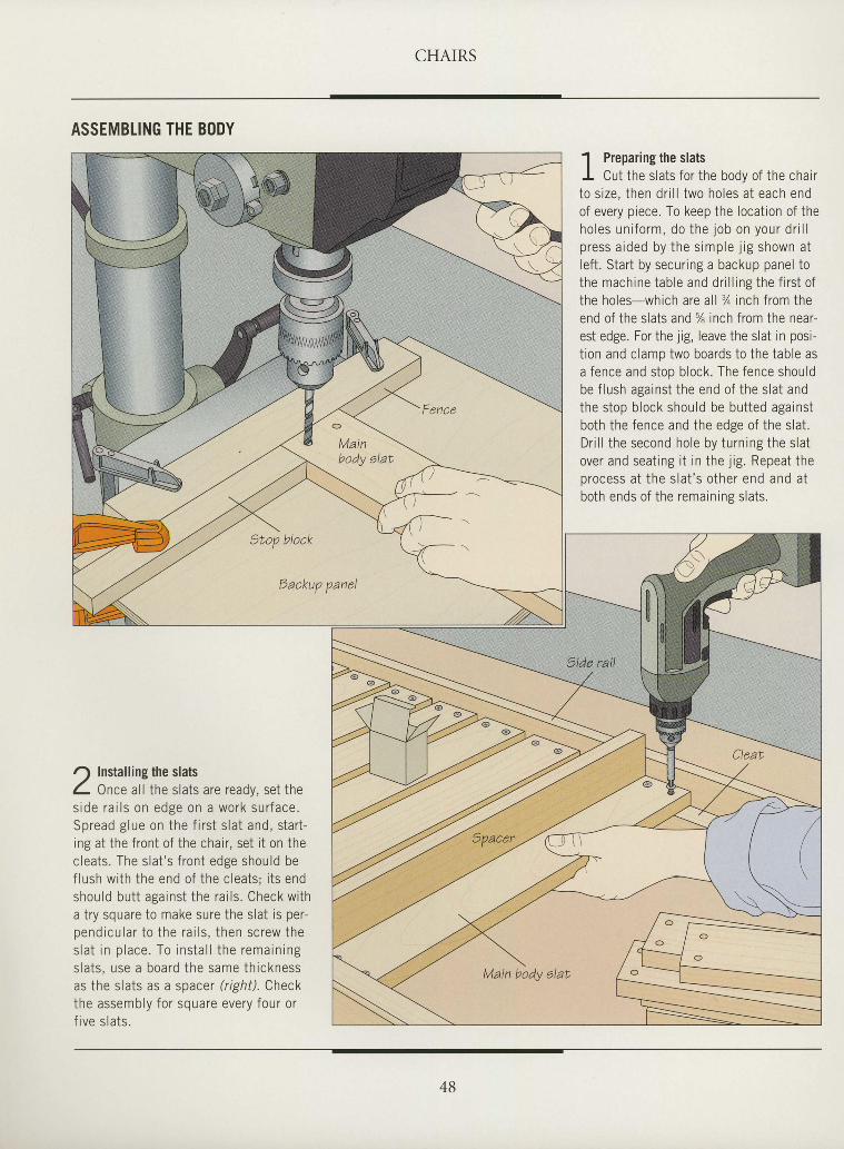
r) Installing the slatsL Once al l the slats are ready, set thes i d e r a i l s o n e d s e o n a w o r k s u r f a c e .s n r p : d o l r r p n n i h p f i r c . f ̂ r ^ + ^ ^ i ^ + ^ - +u p ' u u u 6 r u u v r r L r r u r r r J L > l O t O l l U , ) L C r L -
ing at the f ront of the chai r , set i t on thec lea ts . The s la t ' s f r on t edge shou ld bef l ush w i th t he end o f t he c l ea ts ; i t s endshou ld bu t t aga ins t t he ra i l s . Check w i tha t ry square to make sure the s lat is per-n e n d i c r l a r t o t h e r a i l s . t h e n s c r e w t h es l a t i n p l a c e . T o i n s t a l l t h e r e m a i n i n gs la t s , use a boa rd t he same th i cknessas the slats as a spacer (right). Checkthe assemb ly f o r squa re eve ry f ou r o rf r ve s l a t s .
1 Preoarins the slatsI '
I Cut the s lats for the body of the chai rt o s i ze , t hen d r i l l two ho les a t each endof every p iece. To keep the locat ion of theh o l e s u n i f o r m , d o t h e j o b o n y o u r d r i l lp ress a ided by t he s imp le j i g shown a tle f t . Star t by secur ing a backup panel tothe mach ine tab le and d r i l l i ng t he f i r s t o fthe holes-which are a l l % inch f rom theend of the s lats and % inch f rom the near-est edge. For the j ig , leave the s lat in posi -t ion and c lamp two boards to the table asa fence and stop b lock. The fence shouldbe f lush against the end of the s lat andthe stop b lock should be but ted againstboth the fence and the edge of the s lat .D r i l l t he second ho le by t u rn ing the s la tover and seat ing i t rn the j ig . Repeat then rocess a t t he s l a t ' s o the r end and a tboth ends of the remain ing s lats .
tIIIIIIIIIIItIIIIIIIIIIIIIItIIII
48
CHAIRS
tI
I
I
I
I
tI
I
I
I
I
tIIIIIIIIIIIItIIItII
BUILDING THE BACKREST
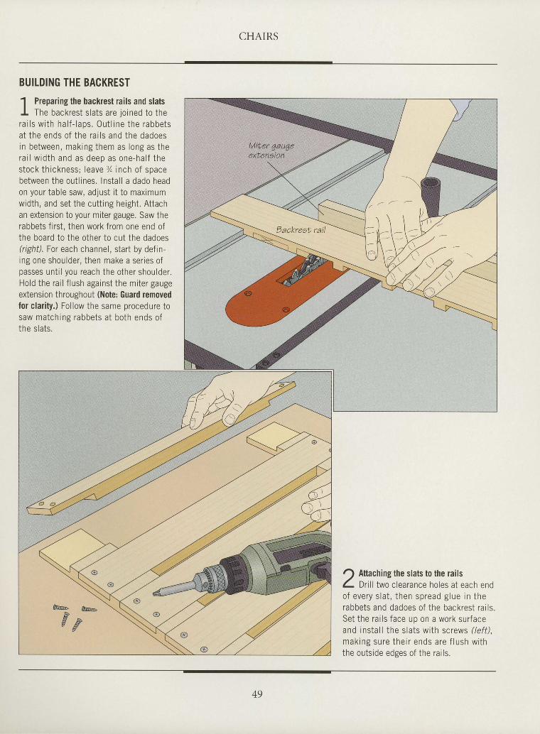
1 Preoarins the backrest rails and slatsI
I The backrest s lats are joined to thera i l s w i th ha l f - laps . 0u t l ine the rabbetsa t the ends o f the ra i l s and the dadoesin be tween, mak ing them as long as thera i l w id th and as deep as one-ha l f thes tock th ickness ; leave Z inch o f spacebetween the out l ines. Instal l a dado headon your table saw, adjust i t to maximumwidth, and set the cutt ing height. Attachan extension to your miter gauge. Saw therabbets f i rst , then work from one end ofthe board to the other to cut the dadoes(r ighi l . For each channel, start by def in-ing one shoulder, then make a ser ies ofpasses unt i l you reach the other shoulder.Hold the rai l f lush against the miter gaugeextension throughout (Note: Guard removedfor clar i ty.) Fol low the same procedure tosaw matching rabbets at both ends ofthe slats.
r) Attaching the slats to the railsL Ol l t two c learance holes at each endo f eve ry s l a t , t hen sp read g lue i n t herabbets and dadoes of the backrest ra i ls .Set the ra i ls face up on a work sur faceand insta l l the s lats wi th screws ( /ef f ) ,mak ing su re t he i r ends a re f l ush w i ththe outs ide edees of the ra i ls .
49
CHAIRS
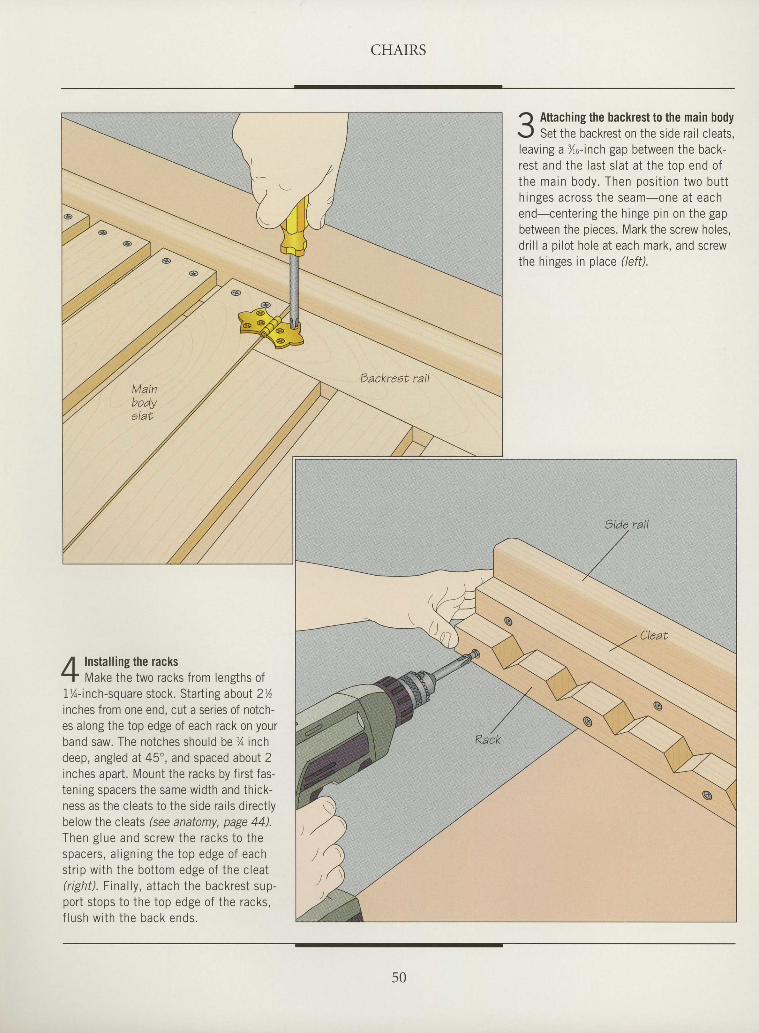
Installing the racksMake the two racks from lensths of
1%-inch-square stock. Starting aboul 2Y,inches from one end, cut a series of notch-es along the top edge of each rack on yourband saw. The notches should be % inchdeep, angled at 45", and spaced about 2inches apart. Mount the racks by first fas-tening spacers the same width and thick-ness as the cleats to the side rai ls direct lybelow the cleats (see anatomy, page 44).Then g lue and screw the racks to thespacers , a l ign ing the top edge o f eachstr ip with the bottom edge of the cleat(r ight) . Final ly, at tach the backrest sup-port stops to the top edge of the racks,f lush w i th the back ends .
J Attaching the backrest to the main body<'
r., l Set the backrest on the side rail cleats,leaving a %o- inch gap between the back-rest and the last s lat at the top end oft he ma in body . Then pos i t i on two bu t th inges ac ross t he seam-one a t eachend-center ing the h inge p in on the gapbetween the pieces. Mark the screw holes,dr i l l a p i lo t hole at each mark, and screwthe hinges in place (left).
I
tITIItIItIttIIIIIIIIIIIIIIttIII
50
CHAIRS
ItItIItI
I
ttIIIIIItIIIttIIIItIIII
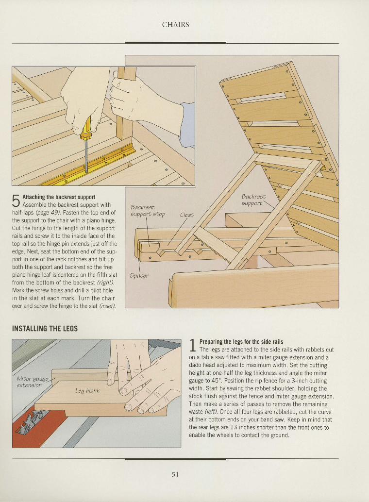
f, Attaching the backrest supportr.,/ Assemble the backrest suooort withhalf-laps @age 49) Fasten the top end ofthe support to the chair with a piano hinge.Cut the hinge to the length of the supportrai ls and screw i t to the inside face of thetop rail so the hinge pin extends just off theedge. Next, seat the bottom end of the sup-port in one of the rack notches and tilt upboth the suooort and backrest so the freepiano hinge leaf is centered on the fifth slatfrom the bottom of the backresl tight).Mark the screw holes and dr i l l a pi lot holein the s la t a t each mark . Turn the cha i rover and screw the hinge to the slat (insef).
INSTATTING THE LEGS' l Preparing the legs for the side railsI The less are attached to the side rai ls with rabbets cuton a tableiaw f i t ted with a miter gauge extension and adado head adjusted to maximum width. Set the cutt ingheight at one-half the leg thickness and angle the mitergauge to 45' . Posit ion the r ip fence for a 3- inch cutt ingwidth. Start by sawing the rabbet shoulder, holding thestock f lush against the fence and miter gauge extension.Then make a ser ies of passes to remove the remainingwasle (lefil. Once all four legs are rabbeted, cut the curveattheir bottom ends on your band saw. Keep in mind thatthe rear legs are 1% inches shorter than the front ones toenable the wheels to contact the sround.
( \ \ \
5 l
CHAIRS
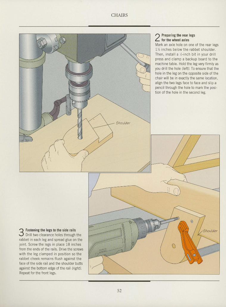
Q Fastening the legs to the side railsr . . l Dr i l l two c learance holes through therabbet in each leg and spread g lue on thejo in t . Sc rew the l egs i n p lace 18 i nchesfrom the ends of the rails. Drive the screwsw i th t he l eg c l amped i n pos i t i on so therabbe i cheek rema ins f l ush aga ins t t heface of the s ide rar l and the shoulder but tsagainst the bottom edge of Ihe rail (righil.
Repeat for the front legs.
r) Preparing the rear legsI tor the wheel axlesMark an axle hole on one of the rear legs1% inches be low the rabbet shou lder .Then, ins ta l l a / , - inch b i t in your d r i l lp ress and c lamp a backup board to themachine table. Hold the leg very f i rmly asyou dr i l l the hole ( lefD.fo ensure that thehole in the leg on the opposite side of thechair wi l l be in exact ly the same locat ion,al ign the two legs face to face and sl ip apenci l through the hole to mark the posi-t ion of the hole in the second les.
IIIIIIttIttI
I
I
I
I
ttIttItItIIIIItt
CHAIRS
IIIIIIIItIIIIIIItIIIIItttIIIIIII
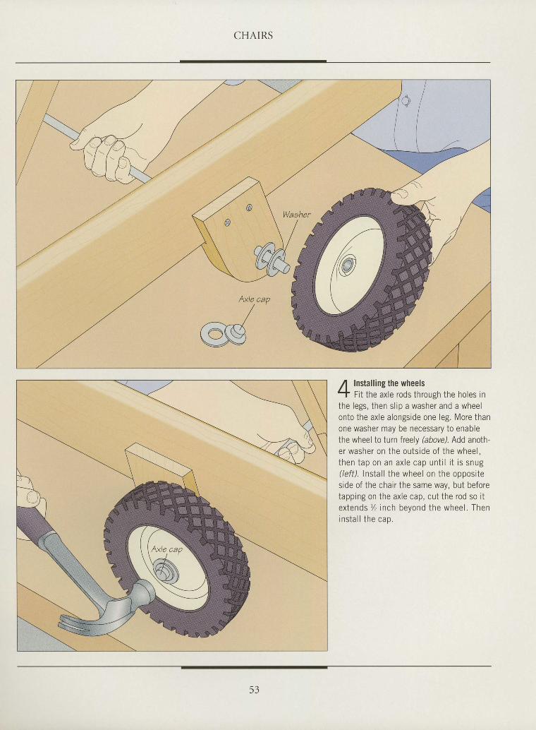
Installing the wheelsFit the axle rods through the holes in
the legs, then sl ip a washer and a wheelonto the axle alongside one leg. More thanone washer may be necessary to enablethe wheel to turn freely (above). Add anoth-er washer on the outside of the wheel,then tap on an ax le cap un t i l i t i s snug(left). lnslall the wheel on the oppositeside of the chair the same way, but beforetapping on the axle cap, cut the rod so itextends % inch beyond the wheel. Thenins ta l l the cao.
53
I
I
I
I
tI
I
I
I
tI
I
tI
I
I
I
I
I
I
I
tI
I
I
tII
he pleasures of a back-yard or flower garden
are meant to be shared. Whilea lone chair mav be suited tosolitary refl ection, benchescall out for company. Morethan anything, a bench is aninvitation, beckoning visitorsto sit and chat or simplyenjoy the surrounding views.
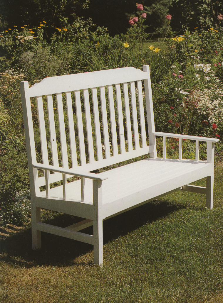
This chapter shows how tobuild three different styles ofbenches. The garden benchshown at left and on the fol-lowing pages will suit moreformal tastes. Its solid, uprightbackrest puts it in characterin a well-ordered garden. Butin the right location, the benchcould also serve as an inter-
BENCHES
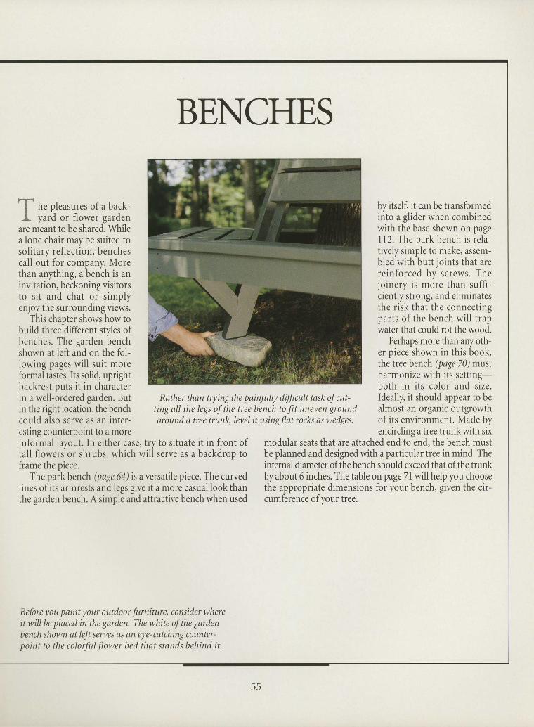
Rather than trying the painfully dfficult task of cut-ting all the legs of the tree bench to fit uneven groundaround a tree trunlg level it using Jlat rocks as wedges.
by itself, it can be transformedinto a glider when combinedwith the base shown on page112. The park bench is rela-tively simple to make, assem-bled with butt joints that arereinforced by screws. Thejoinery is more than suffi-ciently strong, and eliminatesthe risk that the connectingparts of the bench will trapwater that could rot the wood.
Perhaps more than anyoth-er piece shown in this book,the tree bench (page 70) m:ustharmonize with its setting-both in its color and size.Ideally, it should appear to bealmost an organic outgrowthof its environment. Made byencircling a tree trunk with sixesting counterpoint to a more
informal layout. In either case, try to situate it in front oftall flowers or shrubs, which will serve as a backdrop toframe the piece.
The park bench (page 64) is aversatile piece. The curvedlines of its armrests and legs give it a more casual look thanthe garden bench. A simple and attractive bench when used
modular seats that are attached end to end, the bench mustbe planned and designed with a particular tree in mind. Theinternal diameter of the bench should exceed that of the trunkby about 6 inches. The table on page 71 will help you choosethe appropriate dimensions for your bench, given the cir-cumference of your tree.
Before you paint your outdoor furniture, consider whereit will be placed in the garden. The white of the gardenbench shown at left serves as an eye-catching counter-point to the colorful flower bed that stands behind it.
II
55
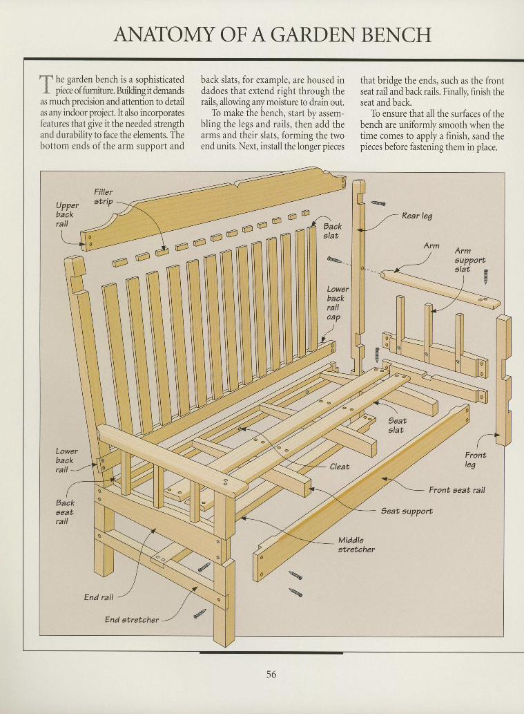
ANATOMY OF A GARDEN BENCH
nI- h. garden bench is a sophisticatedI piece of fumiture. BuiJding it demands
as much precision and attention to detailas any indoor project. It also incorporatesfeatures that give it the needed strengthand durability to face the elements. Thebottom ends ofthe arm support and
back slats, for example, are housed indadoes that extend right through therails, allowing any moisture to drain out.
To make the bench, start by assem-bling the legs and rails, then add thearms and their slats, forming the twoend units. Next, installthe longer pieces
that bridge the ends, such as the frontseat rail and back rails. Finally, finish theseat and back.
To ensure that all the surfaces ofthebench are uniformly smooth when thetime comes to apply a finish, sand thepieces before fastening them in place.
I
tI
I
I
I
tI
I
I
I
I
T
I
I
I
I
I
I
I
I
I
I
I
I
I
Upperbaakrail
Filleratrip
/ ^ e e e
a e - i - n n Ie -
€4€
tr-/
Backelat
LowerbaokrailcaP
9eatalat
Lowerback
Front,leg
rail CIeat
Front, aeat rail
Eackgeatrail
Seat eupport
Middlestretaher
End rail
\
\
End etretaher {
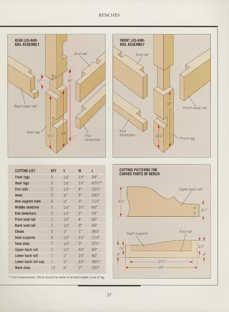
I
I
I
I
I
I
I
I
I
tT
I
I
I
I
rI
I
I
I
I
I
I
I
I
I
I
I
CUTTING PATTERNS FORCURVED PARTS OF BENCH
End rail
Upper back rail
CUTTING LIST QTY T
Front legs
Rear legs
End rails
Arms
Arm support slats 6 3/qu
Middfe stretcher I Iy4'End stretchers 2 Iyo'Front seat rail L lt/o'
Back seat rail I ly4'
Cleats 2 I'Seat supports 4 I%'
Seat slats 7 Iyo"
Upper back rail 1 IYo'Lower back rail 1 1'
Lower back rail cap I %'Back slats 13 ,,6',
2 l'/o'
2 r%'2 Iyo'
2 7 4
t24',47t/o'*
233/"'
2Avt',IIYo'
60"24"OU
60"56'1',a l l / lZ L t A
57Yo'
60"OU
56u/"u
25%',
w!'/ou
I%'
4',? u
74
274
2',4u
3 u
1 u
Z A
4t/n'
Z /4
z ^
Z
BENCHES
Front seat. rail
* Final measurement. Stock should be wider to accommodate curve of les.
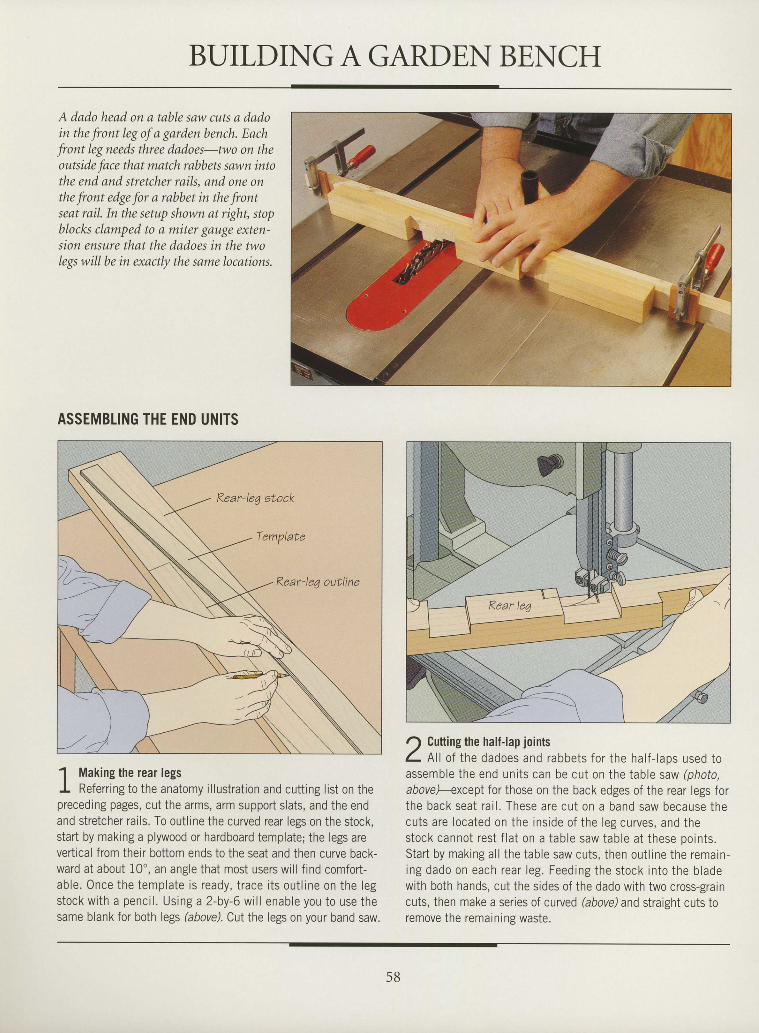
BUILDING A GARDEN BENCH
A dado head on a table saw cuts a dadoin the front leg of a garden bench. Eachfront leg needs three dadoes-two on theoutside face that match rabbets sawn intothe end and stretcher rails, and one onthe front edge for a rabbet in the frontseat rail. In the setup shown at right, stopblocks clamped to a miter gouge exten-sion ensure that the dadoes in the twolegs will be in exactly the same locations.
ASSEMBLING THE END UNITS
1 Making the rear legsI Referring to the anatomy illustration and cutting list on thepreceding pages, cut the arms, arm support slats, and the endand stretcher rails. To outline the curved rear legs on the stock,start by making a plywood or hardboard template; the legs arevertical from their bottom ends to the seat and then curve back-ward at about 10', an angle that most users will find comfort-able. Once the template is ready, trace i ts out l ine on the legstock with a pencrl . Using a 2-by-6 wi l l enable you to use thesame blank for both legs (above). Cut the legs on your band saw.
r) Gutting the half-lap jointsL Xl of the dadoes and rabbets for the half- laps used toassemble the end units can be cut on the table saw (photo,abovel-except for those on the back edges of the rear legs forthe back seat rai l . These are cut on a band saw because thecuts are located on the inside of the leg curves, and thestock cannot rest f lat on a table saw table at these ooints.Start by making al l the table saw cuts, then out l ine the remain-ing dado on each rear leg. Feeding the stock into the bladewith both hands, cut the sides of the dado with two cross-graincuts, then make a series of curved (above) and straight cuts toremove the remaining waste.
I
I
I
I
I
I
I
I
I
I
I
I
I
I
I
I
I
I
T
I
I
I
I
I
I
I
I
I
I
T
I
I
58
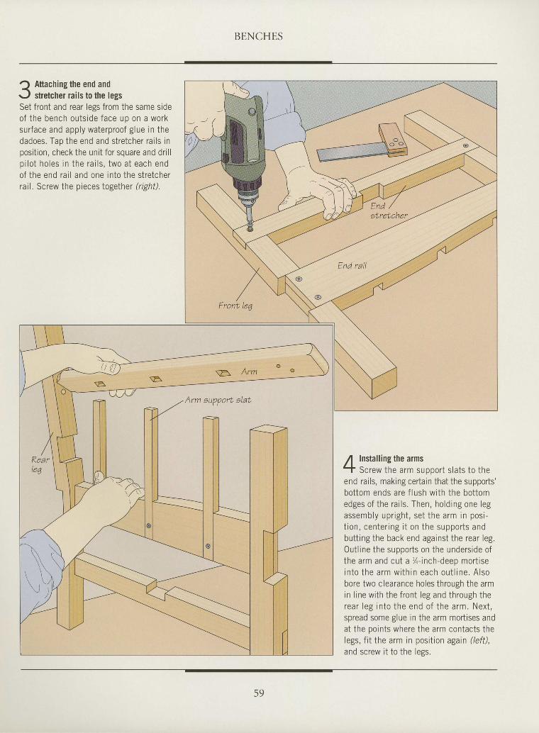
BENCHES
I
I
t
T
tI
I
I
t
tI
I
tI
I
I
T
tI
I
I
tI
I
I
I
I
I
I
I
I
I
Attaching the end andstretcher rails to the legs
Set front and rear legs from the same sideof the bench outside face uo on a worksurface and apply waterproof glue in thedadoes. Tao the end and stretcher rai ls inposit ion, check the unit for square and dr i l lp i lo t ho les in the ra i l s , two a t each endof the end rai l and one into the stretcherrail, Screw the pieces together (righil.
Installing the armsScrew the arm support s lats to the
end rails, making certain that the supports'bottom ends are f lush with the bottomedges of the rai ls. Then, holding one legassembly upr igh t , se t the arm in pos i -t ion , cen ter ing i t on the suppor ts andbutt ing the back end against the rear leg.Outl ine the supports on the underside ofthe arm and cut a %-inch-deep mort isein to the arm wi th in each ou t l ine . A lsobore two clearance holes through the armin l ine with the front leg and through therear leg in to the end o f the arm. Next ,spread some glue in the arm mortises andat the ooints where the arm contacts thelegs, fit the arm in position again (left),and screw it to the legs.
59
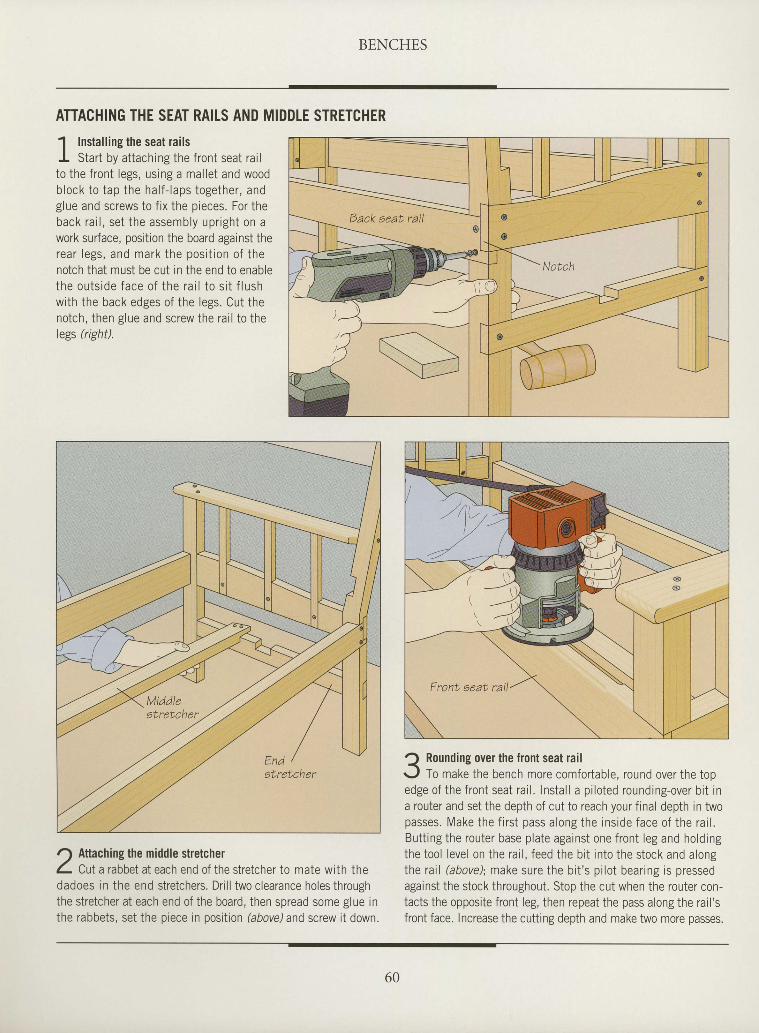
BENCHES
ATTACHING THE SEAT RAILS AND MIDDLE STRETCHER
1 Installing the seat railsI Start by attaching the front seat rai lto the front legs, using a mal let and woodb lock to tap the ha l f - laps together , andglue and screws to f ix the pieces. For theback rai l , set the assembly upright on awork surface, position the board against therear legs , and mark the pos i t ion o f thenotch that must be cut in the end to enablethe ou ts ide face o f the ra i l to s i t f lushwith the back edges of the legs. Cut thenotch, then glue and screw the rai l to thelegs tighil.
r-) Attaching the middle stretcherI Cut a rabbet at each end of the stretcher to mate with thedadoes in the end stretchers. Drill two clearance holes throughthe stretcher at each end of the board, then spread some glue inthe rabbets, set the piece in position (above) and screw it down.
t) Roundins over the front seat railr../ To make the bench more comfortable, round over the topedge of the front seat rai l . Instal l a pi loted rounding-over bi t ina router and set the depth of cut to reach your final depth in twopasses. Make the f i rst pass along the insrde face of the rai l .Butt ing the router base plate against one front leg and holdingthe tool level on the rai l , feed the bi t into the stock and alongthe rai l (above); make sure the bi t 's pi lot bearing is pressedagainst the stock throughout. Stop the cut when the router con-tacts the opposite front leg, then repeat the pass along the rail 'sfront face. Increase the cutting depth and make two more passes.
I
I
tI
I
I
tI
I
I
I
I
I
T
I
tI
I
I
I
I
I
tI
I
I
I
I
I
I
I
I
60
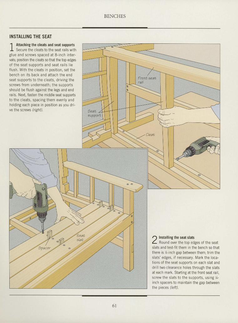
BENCHES
I
I
T
t
I
I
tI
I
I
I
I
I
I
tI
I
I
I
I
I
I
I
I
I
ttI
I
I
tI
INSTATTING THE SEAT
1 Attaching the cleats and seat supportsI Secure the cleats to the seat rai ls withglue and screws spaced at 8- inch inter-vals; position the cleats so that the top edgesof the seat suooor ts and seat ra i l s l ief lush. With the cleats in posit ion, set thebench on i t s back and a t tach the endseat suppor ts to the c lea ts , d r iv ing thescrews from underneath; the supportsshould be f lush against the legs and endrails. Next, fasten the middle seat supporlst n i h p n l o : i q q n : n i n o i h. , r em even l y an0hold ing each p iece in posi t ion as you dr i -ve the screws lnshf).
r) Installing the seat slatsI Rouna over the top edges of the seatslats and testjit them in the bench so thatthere is %-inch gap between them; trim theslats 'edses i f necessary. Mark the loca-t ions of the seat supports on each slat anddri l l two clearance holes through the slatsat each mark. Starting at the front seat rail,screw the slats to the supports, using %-inch spacers to maintain the gap betweenthe pieces (/eff).
6 I
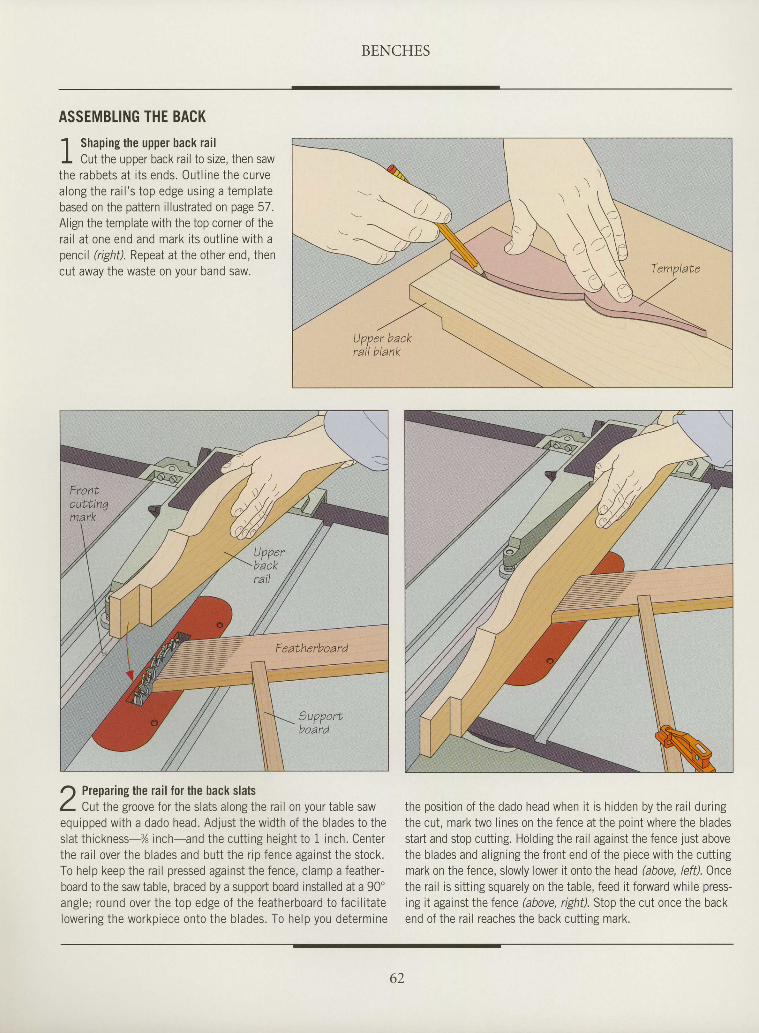
BENCHES
ASSEMBLING THE BACK
1 Shaping the upper back rai lI Cut the upper back rail to size, then sawthe rabbets at i ts ends. Out l ine the curvealong the rai l 's top edge using a templatebased on the pattern illustrated on page 57.Align the template with the top corner of therai l at one end and mark i ts out l ine with apencil (right). Repeat at the other end, thencut away the waste on your band saw.
r) Preparing the rail for the back slatsL Cutthe groove for the slats along the rail on your table sawequipped wi th a dado head. Adjust the width of the b lades to theslat th ickness-X inch-and the cut t ing height to 1 inch. Centerthe ra i l over the b lades and but t the r ip fence against the stock.To help keep the ra i l pressed against the fence, c lamp a feather-board to the saw table, braced by a support board installed at a 90'angle; round over the top edge of the featherboard to fac i l i ta telower ing the workpiece onto the b lades. To help you determine
the posi t ion of the dado head when i t is h idden by the ra i l dur ingthe cut, mark two lines on the fence at the point where the bladesstart and stop cutting. Holding the rail against the fence just abovethe b lades and a l ign ing the f ront end of the p iece wi th the cut t ingmark on the fence, slowly lower it onto the head (above, left). Oncethe rail is sitt ing squarely on the table, feed it fonryard while press-ing it against the fence (above, right). Stop the cut once the backend of the rail reaches the back cuttins mark.
I
I
I
I
tI
I
I
t
I
I
I
I
I
I
I
I
I
I
I
I
I
t
I
I
I
I
I
I
I
I
I
62
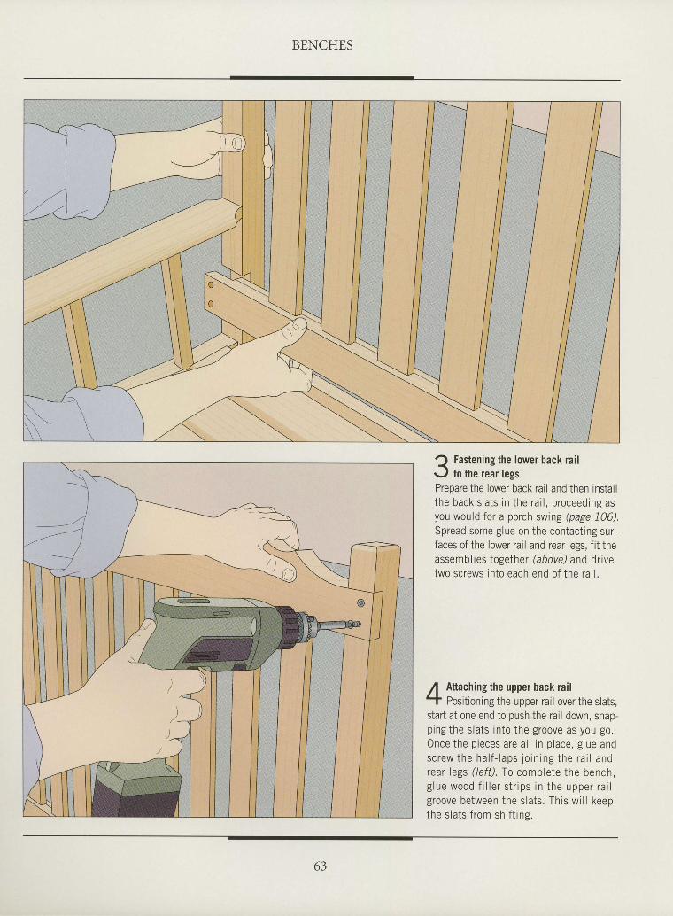
BENCHES
I
I
I
tI
I
I
I
I
I
I
I
I
tI
I
I
I
I
I
I
tI
I
I
I
I
I
I
I
I
I
Fastening the lower back railto the rear legs
Prepare the lower back rail and then installthe back s lats in the ra i l , proceeding asyou would for a porch swing (page 106).Spread some glue on the contact ing sur-faces of the lower rail and rear legs, f it theassembl ies together (abovd and dr ivetwo screws into each end of the ra i l .
Attaching the upper back railPositioning the upper rail over the slats,
start at one end to push the rail down, snap-pingthe slats into the groove as you go.Once the pieces are al l in place, glue andscrew the ha l f - laps jo in ing the ra i l andr p : r l p o c ( l p f f ) f a e n m n l o t o t h o h o n n h
g lue wood f i l l e r s t r ips in the upper ra i lgroove between the slats. This wi l l keepthe slats from shif t ins.
63
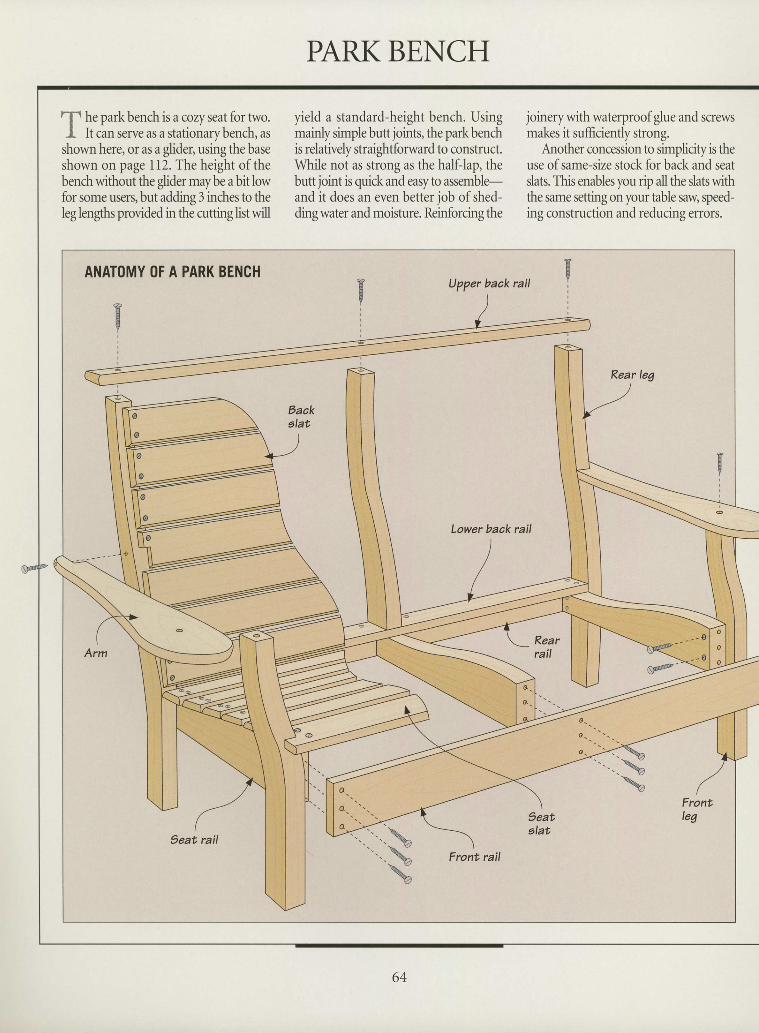
I
I
-f h. park bench is a cozy seat for hvo.I It can serve as a stationary bench, as
shown here, or as a glider, using the baseshown on page 112. The height of thebench without the glider may be a bit lowfor some users, but adding 3 inches to theleg lengths provided in the cutting list will
yield a standard-height bench. Usingmainly simple butt joints, the park benchis relatively straightforward to construct.While not as strong as the half-lap, thebutt joint is quick and easy to assemble-and it does an even better job ofshed-ding water and moisture. Reinforcing the
joinery with waterproof glue and screwsmakes it sufficiently strong.
Another concession to simplicity is theuse of same-size stock for back and seatslats. This enables you rip all the slats withthe same setting on your table saw, speed-ing construction and reducing errors.
tII
I
I
III
I
I
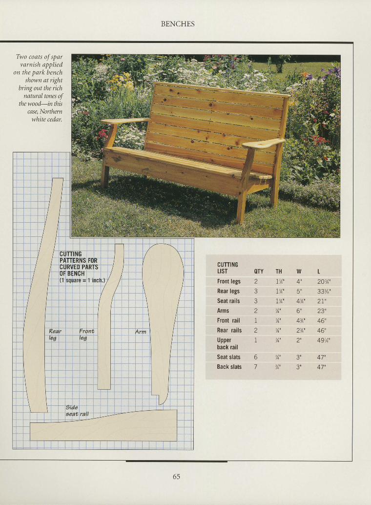
I
I
IIIIIIIIIIIIIIIIIIItItIItI
I
I
BENCHES
Two coats of sparvarnish applied
on the park benchshown at rigfut
bring out the richnatural tones of
thewood-inthismsaNorthern
white cedar.
CUTTIl{GLISTFront legsRear legsSeat railsAmsFront railRear railsUpperback rcilSeat slatsBack slats
OTY TH2 I/4'
3 LY4'
3 lY4'
2 3/4'
I 3/qn
2 % ' ,I 3/on
w4',6n
43/4o
An
43/4'
23/4u
2u
3u
3u
t203/4'
33%',2 t '23',46',46',49Y4'
47',
47',
6
7
-/4
3/4n
65
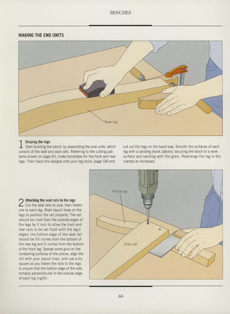
BENCHES
MAKING THE END UNITS
1 Shaping the legsI Start bur ldrng the bench by assembling the end units, whichconsist of the seat and seat rai ls. Referr ing to the cutt ing pat-terns shown on page 65, make templates for the front and rearlegs. Then trace the designs onto your leg stock (page 58) and
/) Aftaching the seat rails to the legsL Cut the seat ra i ls to s ize, then fastenone to each leg. Mark layout l ines on thelegs to posi t ion the ra i l proper ly : The ra i lshould be inset f rom the outs ide edges ofthe legs by % inch to a l low the f ront andrea r ra i l s t o be se t f l ush w i th t he l eg ' sedpes, the bot tom edpe of the seat ra i lshould be 5% inches f rom the bot tom ofthe rear leg and 6 inches f rom the bot tomof the front leg. Spread some glue on thecontacting surfaces of the pieces, align thera i l w i t h you r l ayou t l i nes , and use a t r ysquare as you fasten the ra i ls to the legsto ensure that the bottom edge of the railsremains perpendicular to the outs ide edgeof each leg (right).
cut out the legs on the band saw. Smooth the sur faces of eachleg with a sanding block (above), securing the stock to a worksu r face and sand ing w i th t he g ra in . Rea r range the l eg i n t heclamps as necessary.
I
I
I
I
I
I
I
I
I
I
I
I
I
I
I
I
I
I
I
I
I
I
I
I
I
I
I
I
I
I
I
I
66
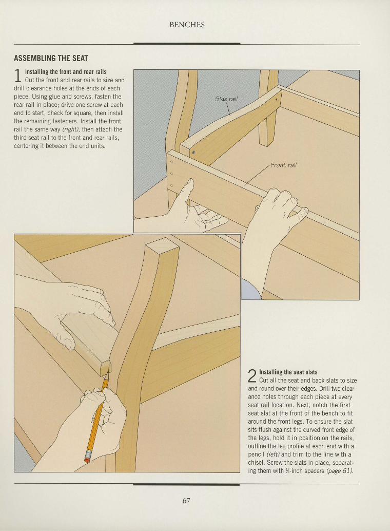
BENCHES
I
I
I
I
I
I
I
I
I
I
I
I
t
I
I
I
I
I
I
I
I
I
I
I
I
I
I
I
I
E
I
I
ASSEMBLING THE SEAT
1 Installing the front and rear railsI Cut the front and rear rai ls to size anddri l l c learance holes at the ends of eachpiece. Using glue and screws, fasten therear rat l in place; dr ive one screw at eachend to start , check for square, then instal lthe remaining fasteners. Instal l the frontrai l the same way (r ight) , then attach thethird seat rai l to the front and rear rai ls,center ine i t between the end units.
O Installing the seat slatsL Cut all the seat and back slats to sizeand round over their edges. Drill two clear-ance holes through each piece at everyseat rai l locat ion. Next, notch the f i rstseat slat at the front of the bench to f i taround the front legs. To ensure the slatsits flush against the curved front edge ofthe legs, hold i t in posi t ion on the rai ls,out l ine the leg prof i le at each end with apencil (lefil and trim to the line with achisel . Screw the slats in place, separat-ing them with %-inch spacers @age 61).
67
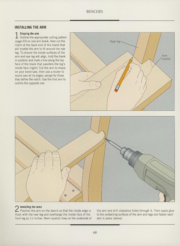
BENCHES
INSTALLING THE ARM
1 Shanine the armI
I 0ut l ine the appropr iate cut t ing pat tern(page 65) on one arm blank, then cut theno tch a t t he back end o f t he b lank tha tw i l l enab le t he a rm to f i t a round the rea rleg. To ensure the ins ide sur faces of thea rm and rea r l eg w i l l a l i gn , ho ld t he b lankin posi t ion and mark a l ine a long the topt ^ ^ ^ ^ t r L ^ L r ^ - r , + L ^ + ̂ " r 2 l l c l q t h p l p o ' ql d L t r U l L l l C U l d l l n L l l d L V u r u i l u ' J
inside face t ight) . Cut the arm to shapeon your band saw, then use a router toround over all its edges, except for thosethat def ine the notch. Use the f i rst arm toout l ine the oooosite one.
Installing the armsPos i t i on t he a rm on the bench so tha t t he i ns ide edse i s
f l ush w i th t he rea r l eg and ove rhangs the i ns ide face o f t hefront leg by 17 inches. Mark locat ion l ines on the unders ide of
t he a rm and d r i l l c l ea rance ho les t h rough i t . Then app l y g lueto the contact ing sur faces of the arm and legs and fasten eacharm in place hbove).
I
I
I
I
I
I
I
t
I
I
I
I
I
I
I
I
I
I
T
I
I
I
I
I
I
I
I
I
I
I
t
I
6B
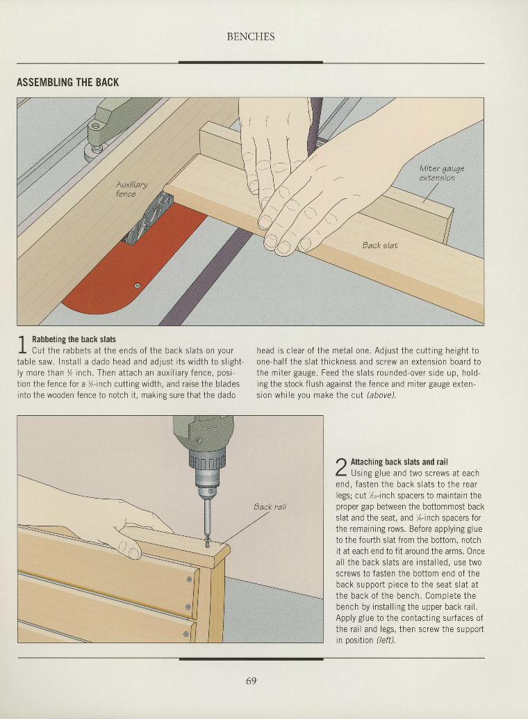
BENCHES
I
I
I
I
I
I
I
I
I
I
ttI
I
I
I
tI
I
I
I
I
tI
I
I
I
tI
I
I
I
ASSEMBTING THE BACK
1 Rabbeting the back slatsI Cut the rabbets a t the ends o f the back s la ts on yourtab le saw. Ins ta l l a dado head and ad jus t i t s w id th to s l igh t -ly more Ihan r l inch. Then attach an auxi l iary fence, posi-t ion the fence for a %-inch cutt ing width, and raise the bladesinto the wooden fence to notch i t , making sure that the dado
head is c lear o f the meta l one. Ad jus t the cu t t ing he igh t toone-half the slat thickness and screw an extension board tothe miter gauge. Feed the slats rounded-over side up, hold-ing the stock f lush against the fence and miter gauge exten-sion whi le you make the cut (above).
( ( (
' l - l -Miter 4augeextenaion
r) Attaching back slats and railL tlttngglue and two screws at eachend, fas ten the back s la ts to the rearlegs; cut Xo-inch spacers to maintain theproper gap between the bottommost backslat and the seat, and %-inch spacers forthe remaining rows. Before applying glueto the fourth slat from the bottom, notchit at each end to fit around the arms. 0ncea l l the back s la ts a re ins ta l led , use twoscrews to fasten the bottom end of theback support piece to the seat slat atthe back o f the bench. Comole te thebench by instal l ing the upper back rai l .Apply glue to the contact ing surfaces ofthe rai l and legs, then screw the supportin position (/eft).
69
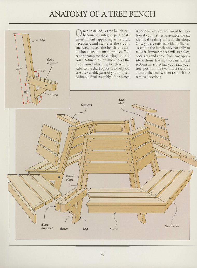
ANATOMYOFATREE BENCHI
I
1\ nce ins ta l led , a t ree bench canL- / b . .o* . an in tegra l par t o f i t senvironment, appearing as natural ,necessary, and stable as the tree i tencircles. Indeed, this bench is by def-ini t ion a custom-made proiect. Youcannot complete the cut i ing l ist unt i lyou measure the circumference of thetree around which the bench will fit.Refer to the chart opposite to help yousize the variable parts ofyour project.Although finalassembly of the bench
is done on site, you will avoid frustra-tion if you first test-assemble the sixident ical seat ing units in the shop.Once you are satisfied with the fit, dis-assemble the bench only part ial ly tomove it. Remove the cap rail, seat, slats,back slats and apron from two oppo-site sections, leaving two pairs of seatsections intact. When you reach yourtree, position the two intact sectionsaround the trunk, then reattach theremoved sections.
I
I
I
I
I
I
I
ttI
I
tI
I
I
I
I
I
I
I
I
I
I
I
I
I
I
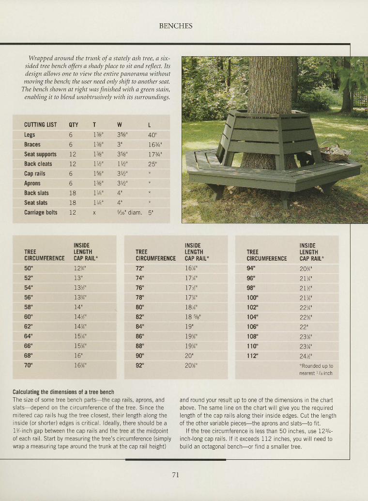
I
I BENCHES
IIIItIIItI
I
I
I
I
I
I
I
I
I
I
tIIIII
OTY66
I 2
I 2
6
6
1 8
1 8
t2
T
LYa"
1%'
lrb'IUz'
1%',
IYB'
IVq'
Wq'
X
w3YB'? 0
3%'
IVz'
3Vz'
3Vz'
4',
+
L
40'
I6T+'
17{q'
2s',
*
Wrapped around the trunk of a stately ash tree, a six-sided tree bench offers a shady place to sit and reJlect. Itsdesign allows one to view the entire panorama withoutmovingthe bench; the user need only shift to another seat.
The bench shown at right was finished with a green stain,enabling it to blend unobtrusively with its surroundings.
CUTTING LISTLegsBracesSeat supportsBack cleatsCap railsApronsBack slatsSeat slatsCariage bolts 7ro" diam. 5n
TREECIRCUMFERENCE50'52"54u
56',
58"
60"
62
64u
66'
68'
70'
INSIDEtEl{GTHCAP RAIL*
I23/4"
13"r3rl'I33/qu
L4'
r4u'I47,6'
I5Y4'
1554',
16 '
76%',
TREECIRCUMFEREilCE72"7+'.76'7g'80'82"u'86'
88'
90'
92"
[{stDETEl{GTHCAP RAIL*
r6,/o'
ITYo'
17w'
L77A'
I8Y4"
18 5/a'
19 '
I93,6'
I9'/o'
20'
20r,6'
TREECIRCUMFERENCE
94u
96'gg'
100"
102"
104'
1 06'
108'
1 10'
112"
INSIDEtEiIGTHCAP RAIL*
203/o'
2IY4'
2rw"2 l%"
22%"
22%',
22',
233,6'
233/4'
24r1',*Rounded up tonearest t /s inch
Galculating the dimensions of a tree benchThe size of some tree bench parts-the cap rails, aprons, andslats-deoend on the circumference of the tree. Since themitered cap rai ls hug the tree closest, their length along theinside (or shorter)edges is cr i t ical . ldeal ly, there should be aI%-inch gap between the cap rails and the tree at the midpointof each rail. Start by measuring the tree's circumference (simplywrap a measuring tape around the trunk at the cap rail height)
and round your result up to one of the dimensions in the chartabove. The same l ine on the chart wi l lg ive you the requiredlength of the cap rai ls along their inside edges. Cut the lengthof the other variable oieces-the aDrons and slats-to fit.
lf the tree circumference is less than 50 inches, use l2slq-inch-long cap rai ls. l f i t exceeds 112 inches, you wi l l need tobuild an octagonal bench-or f ind a smaller tree.
I
I
7 l
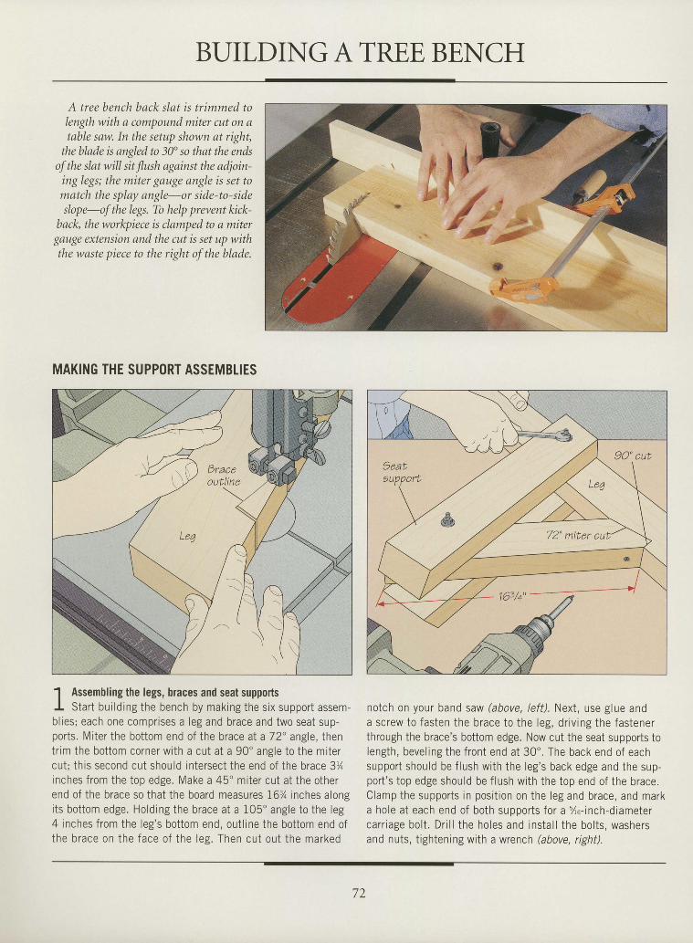
BUILDINGATRE,E BENCH
A tree bench back slqt is trimmed toIength with a compound miter cut on atable saw. In the setup shown at right,
the blade k angled to 30" so that the endsof the slat will sit flush against the adjoin-
ing legs; the miter gauge angle is set tomatch the splay angle-or side-to-sideslope-of the legs. To help prevent kick-
back, the workpiece is clamped to a mitergauge extension and the cut is set up withthe waste piece to the right of the blade.
MAKING THE SUPPORT ASSEMBTIES
1 Assembling the legs, braces and seat supportsI Start bui lding the bench by making the six support assem-bl ies; each one comprises a leg and brace and two seat sup-ports. Miter the bottom end of the brace at a 72" angle, thentr im the bottom corner with a cut at a 90" angle to the mitercut; this second cut should intersect the end of the brace 3%inches from the top edge. Make a 45" miter cut at the otherend of the brace so that the board measures 16% inches alongits bottom edge. Holding the brace at a 105" angle to the leg4 inches from the leg's bottom end, out l ine the bottom end ofthe brace on the face o f the les . Then cu t ou t the marked
notch on your band saw (above, /ef f) . Next, use glue anda screw to fasten the brace to the leg, dr iv ing the fastenerthrough the brace's bottom edge. Now cut the seat supports tolength, bevel ing the front end at 30' . The back end of eachsupport should be f lush with the leg's back edge and the sup-port 's top edge should be f lush with the top end of the brace.Clamp the supports in posit ion on the leg and brace, and marka hole at each end of both supDorts for a %u-inch-diametercarr iage bolt . Dri l l the holes and instal l the bolts, washersand nuts, tightening with a wrench (above, right).
I
I
I
I
I
I
I
I
I
I
I
I
I
I
I
tI
I
I
I
I
I
I
I
I
I
I
I
I
I
I
I
72
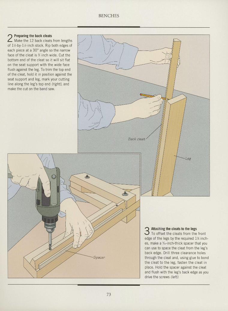
BENCHES
I
I
I
ttI
I
I
I
I
tI
I
I
I
I
I
I
I
ttI
ttI
I
I
I
I
I
I
I
2of
Preparing the back cleatsMake the 12 back cleats from lenghs
l'l-by-I%-inch stock. Rip both edges ofeach p iece at a 30 'angle so the narrowface of the c leat is % inch wide. Cut thebot tom end of the c leat so i t wi l l s i t f la ton the seat suooort wi th the wide facef lush against the leg. To t r im the top endof the c leat , hold i t in posi t ion against theseat support and leg, mark your cut t ingline along the leg's top end (right), andmake the cut on the band saw.
Y
Q Attaching the cleats to the legsr. / To offset the cleats from the frontedge of the legs by the required 1% inch-es, make a %o-inch-thick spacer that youcan use to space the cleat f rom the leg'sback edge. Dr i l l th ree c learance ho lesthrough the cleat and, using glue to bondthe cleat to the leg, fasten the cleat inplace. Hold the spacer against the cleatand f lush with the leg's back edge as youdrive the screws //eff).
73
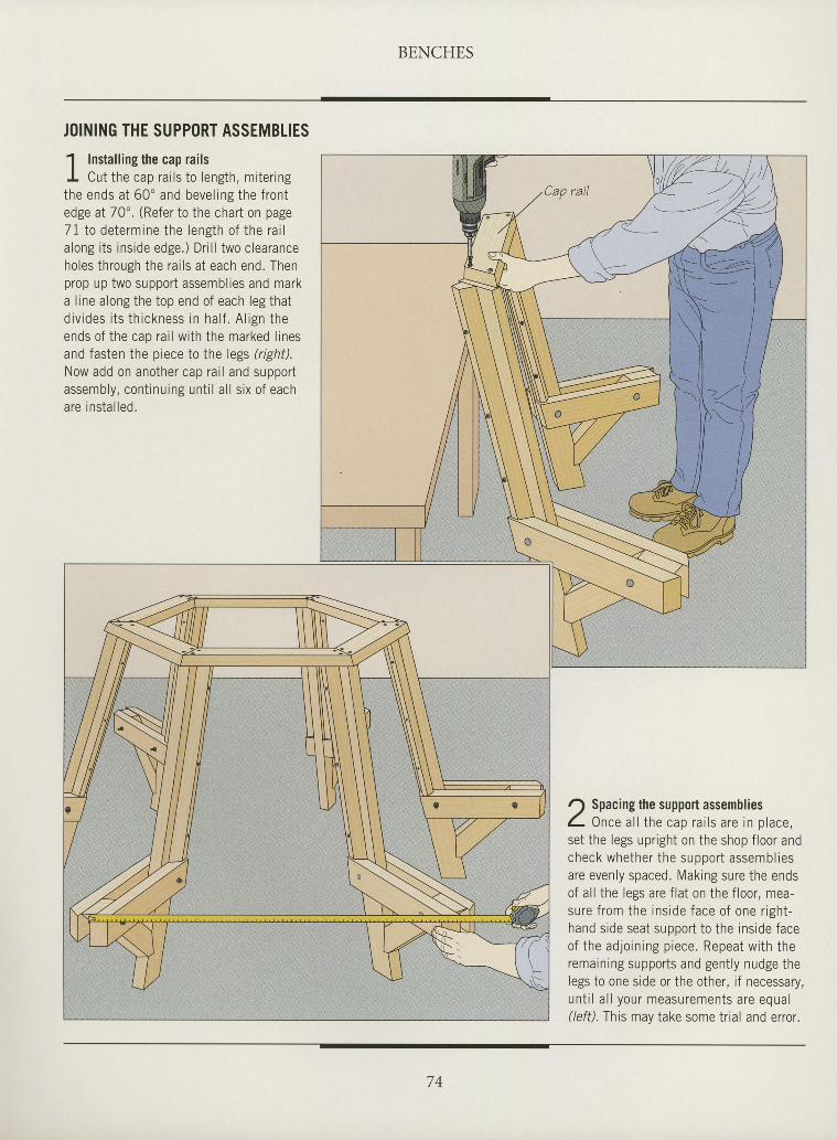
BENCHES
J()INING THE SUPPORT ASSEMBLIES
1 Instal l ins the cao rai lsI Cut the cap ra i l s to length , mi te r ingthe ends a t 60 ' and beve l ing the f ron tedge at 70". (Refer to the chart on page71 to de termine the length o f the ra i lalong i ts inside edge.) Dri l l two clearanceholes through the rai ls at each end. Thenprop up two support assemblies and marka l ine along the top end of each leg thatd iv ides i t s th ickness in ha l f . A l ign theends o f the cap ra i l w i th the marked l ines: nd f as i pn t hp n i pcp t a t ho l pac , l r i oh f I
Now add on another cap ra i l and supportassemb ly , con t i nu ing un t i l a l l s i x o f eacha re i ns ta l l ed .
I
I
I
I
I
I
I
I
I
I
I
I
I
I
I
I
I
I
I
I
I
I
tI
I
I
I
I
I
I
I
I
r) Spacing the support assembliesL Once a l l t he cap ra i l s a re i n p lace ,set the legs upr ight on the shop f loor andcheck whe the r t he suppo r t assemb l i esare evenly spaced. Making sure the endsof a l l the legs are f la t on the f loor , mea-su re f r om the i ns ide face o f one r i gh t -hand s ide seat suooort to the ins ide faceo f t he ad jo in ing p iece . Repea t w i t h t heremain ing supports and gent ly nudge thelegs to one s ide or the other , i f necessary,u n t i l a l l y o u r m e a s u r e m e n t s a r e e q u a l(lefi l .Ihts may take some trial and error.
l)!:- --/.\----,--'tl
74
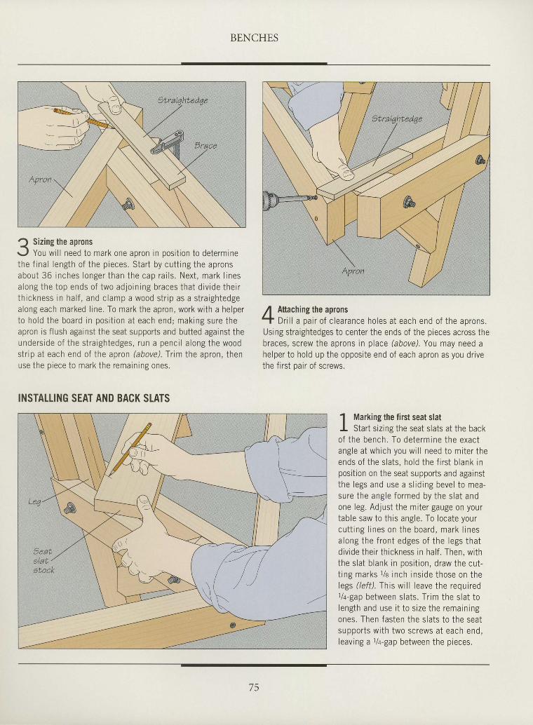
BENCHES
I
I
I
tI
I
I
I
I
I
I
I
I
I
I
I
I
I
I
I
I
I
I
I
I
I
I
I
I
I
I
I
Q Sizing the apronsr-,1 You wi l l need to mark one apron in posit ion to determinethe f ina l leng th o f the p ieces . S tar t by cu t t ing the apronsabout 36 inches longer than the cap ra i l s . Nex t , mark l inesa long the top ends o f two ad jo in ing braces tha t d iv ide the i rth ickness in ha l f , and c lamp a wood s t r ip as a s t ra igh tedgealong each marked l ine. To mark the apron, work with a helperto ho ld the board in pos i t ion a t each end; mak ing sure theapron is f lush against the seat supports and butted against theunders ide o f the s t ra igh tedges, run a penc i l a long the woodstr ip at each end of the apron (above). Tr im the apron, thenuse the piece to mark the remaining ones.
INSTALLING SEAT AND BACK SLATS
Attaching the apronsDri l l a pair of c learance holes at each end of the aprons.
Using straightedges to center the ends of the pieces across thebraces, screw the aprons in place (above). You may need ahelper to hold up the opposite end of each apron as you dr ivethe f irst oair of screws.
1 Marking the first seat slatl -
I Start s iz ins the seat slats at the backof the bench.-To determrne the exactangle at which you wi l l need to miter theends o f the s la ts , ho ld the f i rs t b lank inposition on the seat supports and againstthe legs and use a s l id ing beve l to mea-sure the ang le fo rmed by the s la t andone leg. Adjust the miter gauge on yourtable saw to this angle. To locate yourcu t t ing l ines on the board , mark l inesa long the f ron t edges o f the legs tha tdivide their thickness in half . Then, withthe slat blank in posit ion, draw the cut-t ing marks t /a inch ins ide those on thelegs ( lef t) . This wi l l leave the requiredt/a-gap between slats. Tr im the slat tolength and use i t to size the remainingones. Then fasten the slats to the seatsupports with two screws at each end,leaving a r la-gap between the pieces.
75
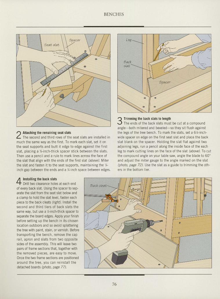
BENCHES
r) Attaching the remaining seat slatsL me second and third rows of the seat slats are instal led inmuch the same way as the f i rst . To mark each slat, set i t onthe seat supports and butt i t edge to edge against the f i rsts la t , p lac ing a %- inch- th ick spacer s t i ck be tween the s la ts .Then use a oenci l and a rule to mark l ines across the face ofthe slat that align with the ends of the first slat hbove). Lliterthe slat and fasten i t to the seat supports, maintaining the %-inch gap between the ends and a %-inch space between edges.
Installing the back slatsDril l two clearance holes at each end
of every back slat. Using the spacer to sep-arate the slat from the seat slat below anda clamp to hold the slat level, fasten eachpiece to the back cleals tighil. Install thesecond and th i rd t ie rs o f back s la ts thesame way, but use a %-inchlhick spacer t0separate the board edges. Apply your finishbefore sett ing up the bench in i ts chosenlocation outdoors and so avoid splatteringthe tree with paint, stain, or varnish. Beforetransport ing the bench, remove the capra i l , apron and s la ts f rom two oppos i tesides of the assembly. This will leave twopairs of frame sections that, together withthe removed pieces, are easy to move.Once the two frame sections are positionedaround the t ree , you can re ins ta l l thedetached boards (photo, page 77).
Q Trimming the back slats to lenghr-,1 The ends of the back slats must be cut at a compoundangle-both mitered and beveled-so they si t f lush againstthe legs of the tree bench. To mark the slats, set a 6%-inch-wide spacer on edge on the f i rst seat slat and place the backs la t b lank on the spacer . Ho ld ing the s la t f la t aga ins t twoadjoining legs, run a penci l along the inside face of the eachleg to mark cutting lines on the face of the slat (above). fo culthe compound angle on yourtable saw, angle the blade to 60'and adjust the miter gauge to the angle marked on the slat(photo, page 72). Use the slat as a guide to trimming the oth-ers in the bottom tier.
IIIIIIIIIIIttI
I
I
t
I
I
I
I
I
I
I
I
I
I
I
I
I
I
I
76
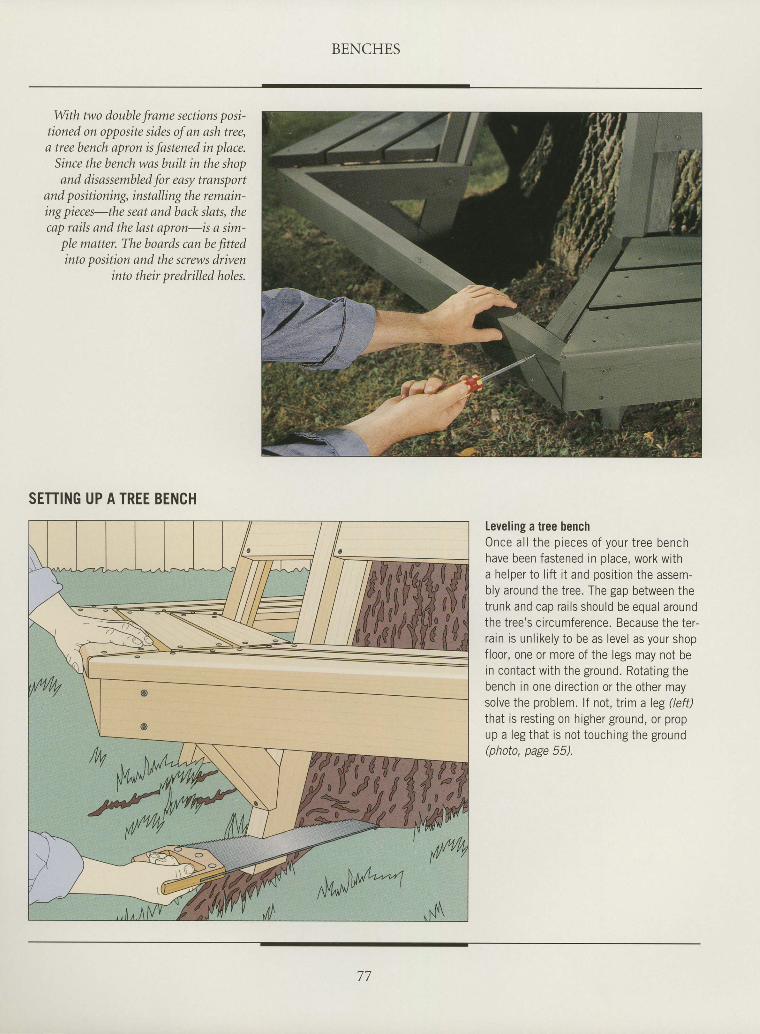
BENCHES
IIItIIIIIIIIIIIIItTtIIIIIIIIIIII
With two double frame sections posi-tioned on opposite sides of an ash tree,a tree bench apron is fastened in place.
Since the bench was buib in the shopand disassembled for easy transport
and positioning, installing the remain-ing pieces-the seat and back slats, thecap rails and the last apron-is a sim-
ple matter. The boerds can be fittedinto positiorL and the screws driven
into their predrilled holes.
SETTING UP A TREE BENCH
Leveling a tree bench0nce a l l the p ieces o f your t ree benchhave been fastened in place, work witha helper to l i f t i t and posit ion the assem-bly around the tree. The gap between thetrunk and cap rai ls should be equal aroundthe tree's circumference. Because the ter-rain is unl ikely to be as level as your shopf loor, one or more of the legs may not bein contact with the ground. Rotat ing thebench in one direct ion or the other maysolve the problem. lf not, trim a leg Ueft)that is rest ing on higher ground, or propup a leg that is not touching the ground(nhnfn neop 56)
77
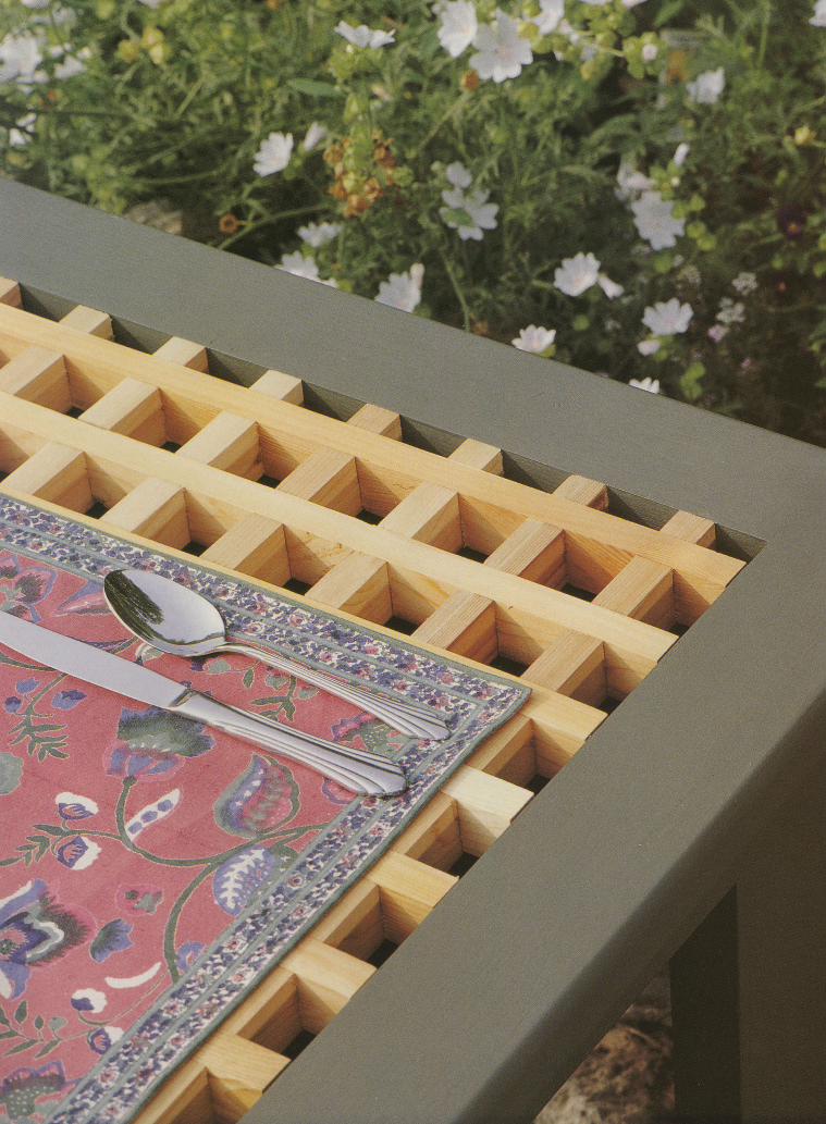
5 . ? E $
eL."
_ =
+ a
rJl\;rt
tr i gor' ,- :',,. .tF:,.-,.%:+-
I ra_..s4;.s: ;;T*{:#':.ry*
""**"* ..r::tly
S ,i' *:iirfi%:II,,tt
Ls* rE
#: : t ; :' v,.i] {th* .r,.: I'u*
;Ff#"li*{c -t?",
v) U,:- , ' , ' lF
tij l-.,*
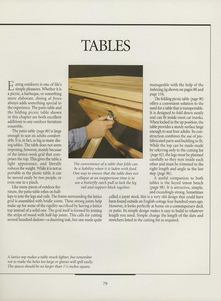
II
IItIIIIIIIIIIIttIIItIIIIII
ating outdoors is one of life'ssimple pleasures. Whether it is
a picnic, a barbeque, or somethingmore elaborate, dining al frescoalways adds something special tothe experience. The patio table andthe folding picnic table shownin this chapter are both excellentadditions to any outdoor furnitureensemble.
The patio table (page 80) is largeenough to seat six adults comfort-ably. It is, in fact, as big as many din-ing tables. The table does not seemimposing, howeve5 mainly becauseof the lattice-work grid that com-prises the top. This gives the table alight appearance, and literallyreduces theweight. While it is not asportable as the picnic table, it canbe moved easily by hvo people, oreven one in a pinch.
Like many pieces of outdoor fur-niture, the patio table relies on half-
TABLES
The convenience of a table that folds canbe a liability when it is laden with food.
One way to ensure that the table does notcollapse at an inopportune time is to
use a butterfly catch pull to lock the legrail and support block together.
manageable with the help of theindexing jig shown on pages 88 andpage 134.
The folding picnic table (page 90)offers a convenient solution to theneed for a table that is transportable.It is designed to fold down neatlyand can fit inside most car trunks.When locked in the up position, thetable provides a sturdy surface largeenough to seat four adults. Its con-struction combines the use of nre-fabricated parts and building to fit.While the top can be made madeby referring only to the cutting list(page 92), the legs must be plannedcarefully so they nest inside eachother and must be trimmed to theright length and angle as the laststep (page 96).
A useful companion to bothtables is the keyed tenon bench(page 98).lt is attractive, simple,and exceedingly strong. Sometimes
laps to join the legs and rails. The frame surrounding the latticegrid is assembled with bridle joints. These strong joints helpmake up for some of the rigidity sacrificed by having a latticetop instead of a solid one. The grid itself is formed by joiningthe strips of wood with half-lap joints. This calls for cuttingseveral hundred dadoes-a daunting task, but one made quite
called a joynt stool, this is a very old design that could havebeen found outside an English cottage four hundred years ago.However, it looks perfectly at home on a contemporary deckor patio. Its simple design makes it easy to build to whateverlength you need. Simple change the length of the slats andstretchers listed in the cutting list as required.
A lanice top makes a table much lighter, but remembernot to make the holes too large or glasses will spill easily.The spaces should be no larger than 11/t inches square.
II
79
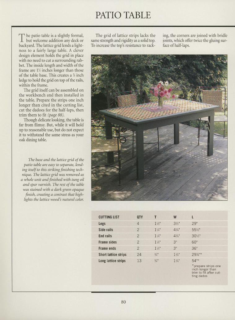
he patio table is a slightly formal,but welcome addition any deck or
The grid of lattice strips lacks thesame strength and rigidity as a solid top.To increase the top's resistance to rack-
ing, the corners are joined with bridlejoints, which offer twice the gluing sur-face ofhalf-laps.
IIIItIIIItIIIIIIIIItIIItII
backyard. The lattice grid lends a lighrness to a fairly large table. A cleverdesign element holds the grid in placewith no need to cut a surrounding rab-bet. The inside length and width of theframe are 1% inches longer than thoseof the table base. This creates a%inchledge to hold the grid on top of the rails,within the frame.
The grid itself can be assembled onthe workbench and then installed inthe table. Prepare the strips one inchlonger than cited in the cutting list,cut the dadoes for the half-laps, thentrim them to fit (page 88).
Though delicate looking, the table isfar from flimsy. But, while it will holdup to reasonable use, but do not expectit to withstand the same stress as youroak dining table.
The base and the lattice grid of thepatio table are easy to separate, lend-
ing itself to this striking finishing tech-nique. The lattice grid was removed as
a whole unit and finished with tung oiland spar varnish. The rest of the tablewas stained with a dark green opaquefinish, creating a contrast that high-lights the lattice wood's natural color.
CUTTI]IG TISTIegsSide railsEnd railsFrame sidesFrame endsShoil lattice stdpsLong lattice strips
OTY422222413
TTY,'IYo'
IY4'
1Y4'
IYo'
Y4'
Y4'
w3Y2'
4Y4'
4Y4'
3u
3u
IY4'
IY4'
t29',5s%',30t/z'
60'36'297/s'*
54u**prepare strips oneinch longer thantrim to fit after cut-t ing dados
II
II
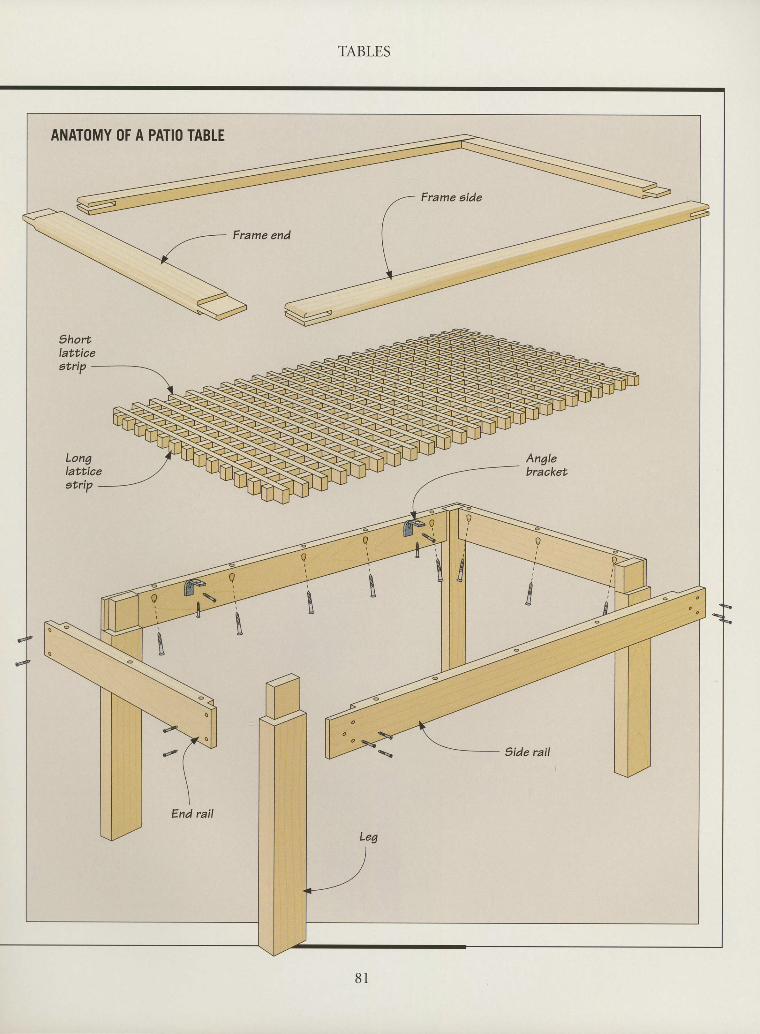
It TABLES
ANATOMY OF A PATIO TABTE
Frame end
Shortlat'ticeet'rip -
Longlatticeetrip -
h
Leg
9ide rail
End rail
\
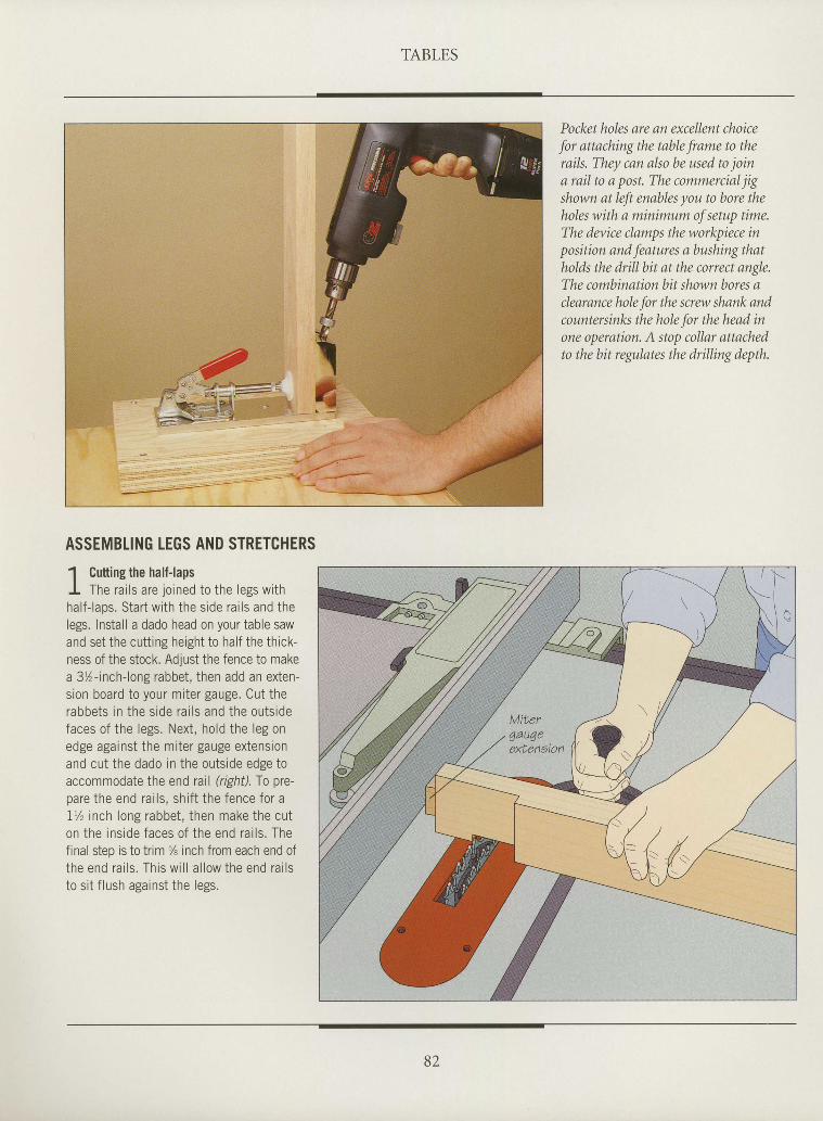
TABLES
Pocket hLtlcs are au cxccllurt cltoicc
.fbr nttnclrirtg tlrc tnltla .fi'tttrc to thcroils. Tlrcy cntt slso lte trsed to .joirra roil to o post. Tlrc cLtrrtncrcid.i igshowrt ttt lc.ft etnltles yotr to Itore tltelnlcs witlr s rtt irrirrrturr o.f setup tirrte.Tlrc davice clnrrrps tlrc workpiece itrpositiort arrd.f-cottrres o Ittrshitry tlntholds tlrc dri l l bit ot the correct nttglc.The corri lt irtttt i tttt l t i t slutwrr bttres scleqrarrce lrclc.fbr tlrc screw sl.Lnrtk nrulcotute rsittks tlrc ltole .fbr t lrc lrcod irrorre opernliort. A stop cLtl lar attschedto tlre bit rcgilotcs tlrc drilling dcpth.
I
I
I
I
I
I
I
I
I
I
I
I
I
I
I
I
I
I
I
I
I
I
I
I
I
I
I
I
tI
I
I
ASSEMBLING LEGS AND STRETCHERS
1 Cuttins the half-lansl -
I The ra i ls are jo ined to the legs wi thhal f - laps. Star t wi th the s ide ra j ls and thelegs. Insta l l a dado head on your table sawand set the crr t t ins heipht to hal f the thrck-ness of the stock. Adjust the fence to makea 3 l - inch- long rabbet , then add an exten-sron board to your mi ter gauge. Cut therabbe ts i n t he s i de ra i l s and the ou ts idefaces of the legs. Next , hold the leg onp d s p : o : i n c . f i h p m i f o r o a r r o o p v t p n s i n n
and cut the dado in the outs ide edge toaccommodate the end ratl (right). To pre-pare the end ra i ls , sh i f t the fence for a1 ' l - i nch l ong rabbe t , t hen make the cu ton the i ns ide faces o f t he end ra i l s . Thefinal step is to trim % inch from each end oft he end ra i l s . Th i s w i l l a l l ow the end ra i l sto s i t f lush against the legs.
B2
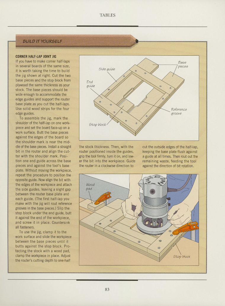
TABLES
IIIttIttI
tIIIIIIIIIIIIIIIIIIItI
I
CORNER HALF.IAP JOINT JIGlf you have to make corner half-lapsin several boards of the same size,i t is worth taking the t ime to bui ldthe j ig shown at r ight. Cut the twobase pieces and the stop block fromplywood the same thickness as yoursiock. The base pieces should bewide enough to accommodate theedge guides and support the routerbase plate as you cut the half-laps.Use sol id wood str ips for the fourp d o o o r r i d p c
To assemble the j ig , mark theshoulder of the half-lap on one work-piece and set the board face-up on awork surface. Butt the base oiecesagainst the edges of the board sothe shoulder mark is near the mid-dle of the base pieces. Install a straightbi t in the router and al ign the cut-ter with the shoulder mark. Posi-t ion one end guide across the basepieces and against the iool 's baseplate. Without moving the workpiece,repeat the procedure to position theopposite guide. Now align the bit withthe edges of the workpiece and attachthe side guides, leaving a sl ight gapbetween the router base olate andeach guide. (The f i rst hal f- lap youmake with the jig will rout referencegrooves in the base pieces.) Slip thestop block under the end guide, butti t against the end of the workpiece,and screw i t in place. Countersinkall fasteners.
To use the j ig, c lamp i t to thework surface and slide the workoiecebetween the base pieces unt i l i tbutts against the stop block. Pro-tect ing the stock with a wood pad,clamp the workpiece in place. Adjustthe router's cutting depth to one-half
the stock thickness. Then, with therouter posi t ioned inside the guides,grip the tool firmly, turn it on, and low-er the bi t into the workoiece. Guidethe router in a clockwise direction to
cut the outside edges of the half-lap,keeping the base plate flush againsta guide at all times. Then rout out theremaining waste, feeding the toolagainst the direction of bit rotation.
83
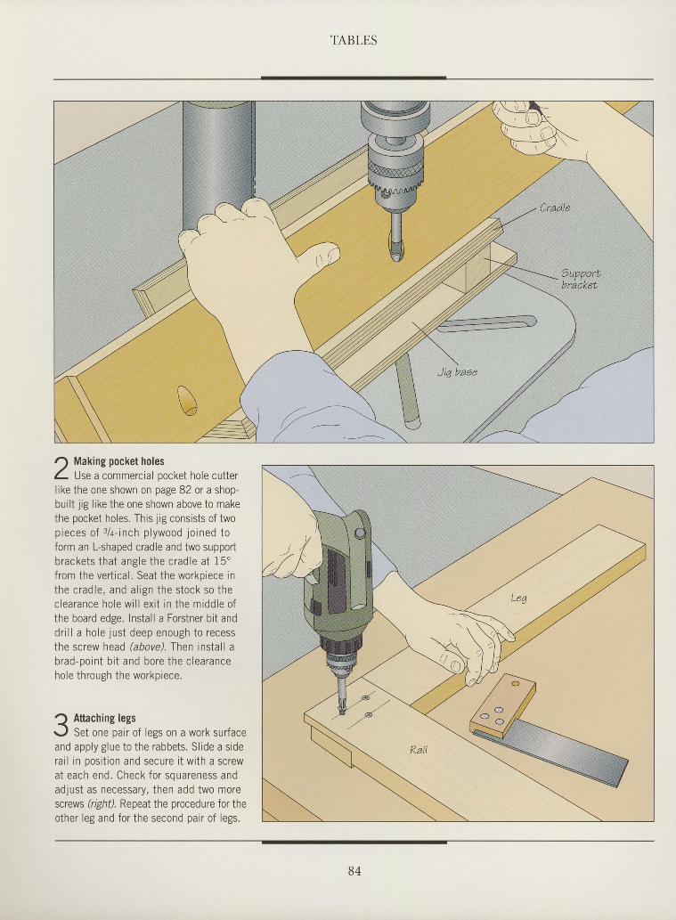
TABLES
IIItIIIIIttIIIIIIItIIIIIIIIIItIt
Making pocket holesUse a commercial pocket hole cutter
l ike the one shown on page 82 or a shop-bui l t j ig l ike the one shown above to makethe pocket holes. This 1ig consists of twop ieces o f : / a - i nch p l ywood j o i ned toform an L-shaped cradle and two supportb racke ts t ha t ang le t he c rad le a t 1 5 "f rom the ver t ica l . Seat the workprece inthe c rad le , and a l i gn t he s tock so thec lea rance ho le w i l l ex i t i n t he m idd le o fthe board edge. Install a Forstner bit andd r i l l a ho le j us t deep enough to recessthe screw head (above). Then insta l l ab rad -po in t b i t and bo re t he c lea rancehole through the workpiece.
Q Attaching legsr-,1 Set one pair of legs on a work surfaceand apply glue to the rabbets. Sl ide a siderai l in posi t ion and secure i t with a screwat each end. Check fo r souareness andadjust as necessary, then add two morescrews (right). Repeat the procedure for then i h p r l p o a n d f n r i h p q o . n n d n r i r n f l p o q
B4
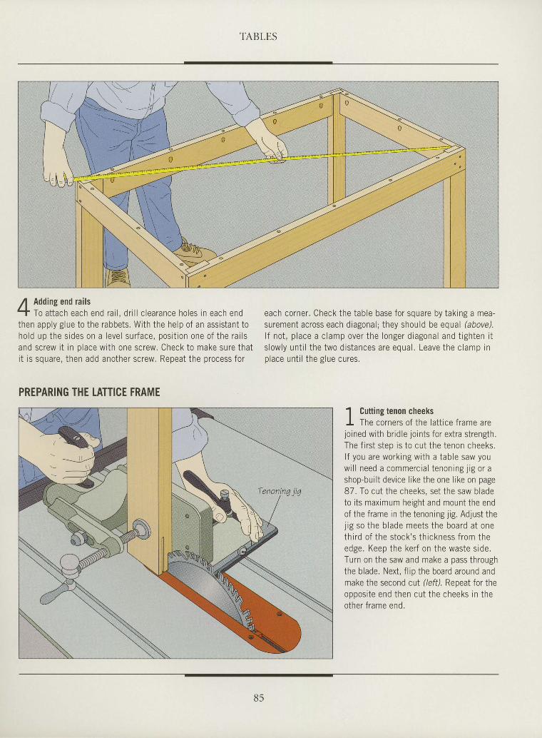
TABLES
IIItIIIIIIIIIrI
tItI
I
I
I
I
I
I
I
I
I
I
I
I
I
Adding end rai lsTo a t t ach each end ra i l , d r i l l c l ea rance ho les i n each end
then apply glue to the rabbets. With the help of an assistant toho ld up the s ides on a leve l sur face , pos i t ion one o f the ra i l sand screw i t in olace with one screw. Check to make sure that, + t - ^ ^ , , ^ - ^ + L ^ ^ ^ r r - r n t h p r s a r p w R e n p : t t h p n r n a p s s f n rI t l J ) q u d l c , t l l c l l d u u d l r v L r r c r J u r c v v . r \ c p c o L L r r s r
each corner . Check the table base for square by tak ing a mea-surement across each d iagonal ; they should be equal (above).
l f no t , p l ace a c l amp ove r t he l onge r d iagona l and t i gh ten i ts l ow ly un t i l t he two d i s tances a re equa l . Leave the c lamp i nn l : e c r r n t i l t h p o l r r c n r r r p .p , u u r u , ' 1 , ' L ' , u E , u u u u , u J .
PREPARING THE LATTICE FRAME
1 Cuttins tenon cheeksI -
I The corners of the la t t ice f rame arejo ined wi th br id le jo ints for ext ra st rength.The f i r s t s ten i s t o c l t t he t enon cheeks .l f you are work ing wi th a table saw youw i l l need a commerc ia l t enon ing j r g o r ashop-bui l t device l ike the one l ike on page87 To cut the cheeks set the saw bladeto i ts maximum height and mount the endof the f rame in the tenoning j ig . Adjust thei i p so t he h lade mee ts t he boa rd a t oneth i rd o f t he s tock ' s t h i ckness f rom theedse . Keen the ke r f on t he was te s i de .Turn on the saw and make a pass throughthe b lade. Next , f l ip the board around andmake the second cut (left). Repeat for theoppos i t e end then cu t t he cheeks i n t heother f rame end.
B5
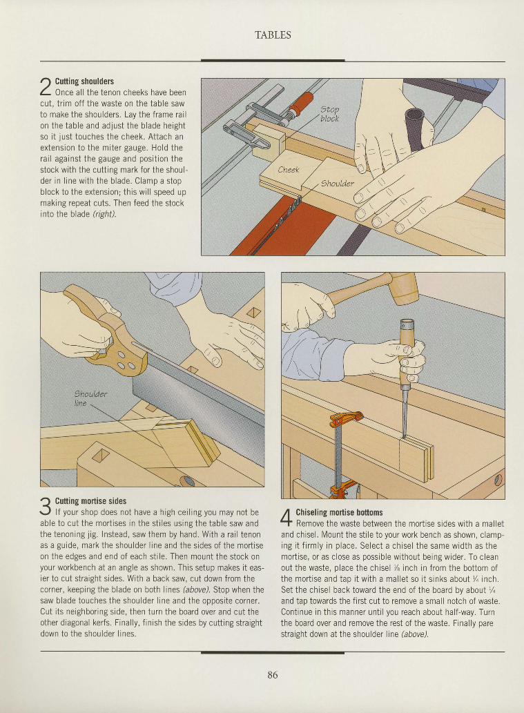
TABLES
r) Cutting shouldersL Onr" al l the tenon cheeks have beencut, t r im off the waste on the table sawto make the shoulders. Lay the frame rai lon the tab le and ad jus t the b lade he igh tso i t just touches the cheek. Attach anex tens ion to the mi te r gauge. Ho ld thera i l aga ins t the gauge and pos i t ion thestock with the cutt ing mark for the shoul-der in l ine w i th the b lade. C lamo a s tooblock to the extension; this wi l l speed upmaking repeat cuts. Then feed the stockinto the blade ?ighil.
Q Cutting mortise sidesr-,1 l f your shop does not have a high cei l ing you may not beable to cut the mort ises in the st i les using the table saw andthe tenoning j ig. Instead, saw them by hand. With a rai l tenonas a guide, mark the shoulder l ine and the sides of the mort iseon the edges and end of each st i le. Then mount the stock onyour workbench at an angle as shown. This setup makes i t eas-ier to cut straight s ides. With a back saw, cut down from thecorner, keeping the blade on both lines (above). Stop when thesaw blade touches the shoulder l ine and the opposite corner.Cut i ts neighboring side, then turn the board over and cut theother diagonal kerfs. Final ly, f in ish the sides by cutt ing straightdown to the shou lder l ines .
Chiseling mortise bottomsRemove the waste between the mort ise sides with a mal let
and chisel . Mount the st i le to your work bench as shown, c lamp-ing i t f i rm ly i n p lace . Se lec t a ch i se l t he same w id th as t hemort ise, or as c lose as possib le wi thout being wider . To c leanout the waste, o lace the chisel % inch in f rom the bot tom ofthe mor t i se and tap i t w i t h a ma l l e t so i t s i nks abou t % inch .Set the chisel back toward the end of the board by aboul ' /oand tap towards the first cut to remove a small notch of waste.Cont inue in th is manner unt i l you reach about hal f -way. Turnthe board over and remove the rest of the waste. Finallv oarestraight down at the shoulder l ine (above).
IItItIIIIIIIIIIIIIIIIIIIIttIIttI
86
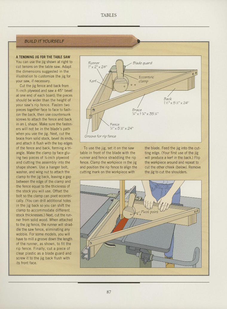
TABLES
I
I
I
I
I
I
I
I
tI
I
I
I
tI
tII
tI
tItI
I
I
I
I
I
I
I
I
A TENONING JIG FOR THE TABLE SAWYou can use the l ig shown at r ight tocut tenons on the table saw. Adaptthe d imens ions suggested in thei l lustrat ion to customize the j ig foryour saw, if necessary.
Cut the i is fence and back from%-inch plywood and saw a 45' bevelat one end of each board; the piecesshou ld be w ider than the he igh t o fyour saw 's r ip fence. Fas ten twonieces topether face to face to fash-
ion the back, then use countersunkscrews to attach the fence and backin an L shape. Make sure the fasten-ers w i l l no t be in the b lade 's pa thwhen you use the j ig. Next, cut thebrace from solid stock, bevel its ends,and attach it flush with the top edgesof the fence and back, formrng a tr i -angle. Make the clamp by face glu-ing two p ieces o f l - inch p lywoodand cu t t ing the assembly in to theshape shown. Use a hanger bo l t ,washer, and wing nut to attach thec lamp to the 1 ig back , leav ing a gapbetween the edge of the clamp andt hp f pnnp pn r r : l f n i ho i h l 6 l angg5 g f
the stock you wi l l use. Of fset thebol t so the c lamp can p ivot eccentr i -ca l ly . (You can dr i l l addi t ional holesin the j ig back so you can shi f t thec lamp to accommoda te d i f f e ren tstock thicknesses.) Next, cut the run-ner f rom sol id wood. When at tachedto the l ig fence, the runner wi l l s t rad-d le t he saw fence , e l im ina t i ng anywobble. For some models, you wi l lhave to mill a groove down the lengtho f t he runne r , as shown , t o f i t t her i p f e n c e . F i n a l l y , c u t a p r e c e o fc l ea r p las t i c as a b lade gua rd andsc rew i t t o t he j i g back f l ush w i thi ts f ront face.
To use the i is . set i t on the sawJ i 6 r
e v ! i r v
tab le in f ron t o f the b lade w i th therunner and fence s t radd l ing the r ipfence. Clamp the workpiece in the j igand posit ion the r ip fence to al ign thecutt ing mark on the workpiece with
the b lade. Feed the j ig in to the cut-t ing edge. (Your f i rs t use of the j ig
wi l l produce a ker f in the back.) F l ipthe workpiece around and repeat tocut the other cheek (below). Removethe .1 ig to cut the shoulders.
Dlade 4uard
Fence
Groove for np fence
B7
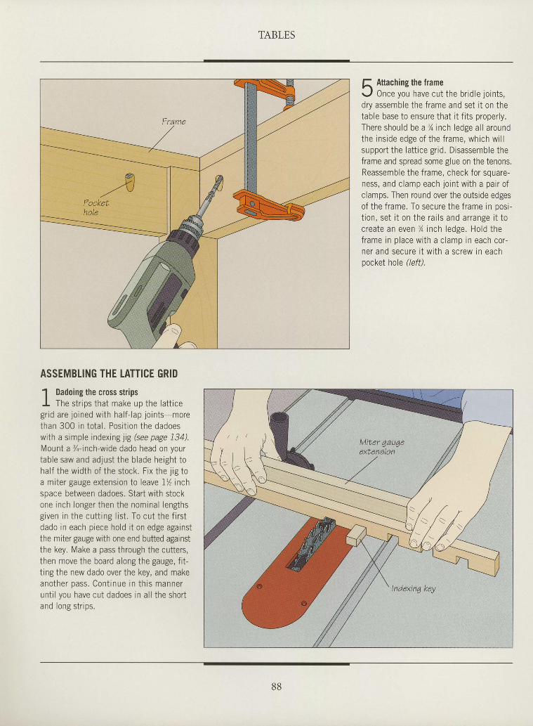
TABLES
f, Attaching the framer-,f Once you have cut the bridle joints,dry assemble the frame and set it on thetable base to ensure that it fits properly.There should be a % inch ledge al l aroundthe inside edge of the frame, which wi l lsupport the lat t ice gr id. Disassemble theframe and spread some glue on the tenons.Reassemble the frame, check for square-ness, and clamp each joint with a pair ofclamps. Then round over the outside edgesof the frame. To secure the frame in posi-t ion, set i t on the rai ls and arrange i t tocreate an even 3/o inch ledge. Hold theframe in place with a clamp in each cor-ner and secure i t with a screw in eachpocket hole (/eff).
IIIIttI
I
I
ttIIIIIItItIItIIItrIItI
ASSEMBLING THE LATTICE GRID
1 Dadoing the cross stripsI The str ips that make up the lat t icegrid are joined with half- lap joints-morethan 300 in total . Posit ion the dadoeswith a simple indexing jig (see page 134).Mount a %-inch-wide dado head on yourtable saw and adjust the blade height tohalf the width of the stock. Fix the j ig toa miter gauge extension to leave IYz inchspace between dadoes. Start with stockone inch longer then the nominal lengthsgiven in the cutt ing l ist . To cut the f i rstdado in each piece hold i t on edge againstthe miter gauge with one end butted againstthe key. Make a pass through the cutters,then move the board along the gauge, fit-ting the new dado over the key, and makeanother pass . Cont inue in th is mannerunt i l you have cut dadoes in al l the shortand long str ips.
88
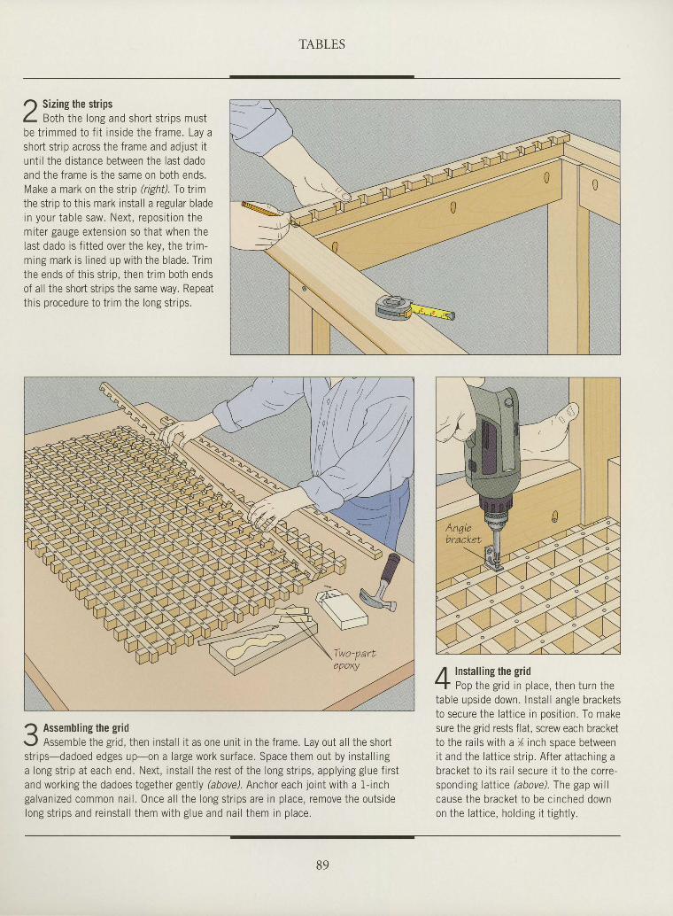
TABLES
ttIIIIttIIIItIIIIIIIItIItIIIIItt
r) Sizing the stripsL gotn the long and short str ips mustbe tr immed to f i t inside the frame. Lay ashort strip across the frame and adjust itunt i l the distance between the last dadoand the frame is the same on both ends.Make a mark on the strip (righil, f o timthe strrp to this mark instal l a regular bladein your tab le saw. Next , repos i t ion themiter gauge extension so that when thelast dado is f i t ted over the key, the tr im-ming mark is l ined up with the blade. Tr imthe ends of this str io. then tr im both endsof all the short strips the same way. Repeatthis procedure to tr im the long str ips.
Assembling the gridAssemble the gr id, then insta l l i t as one uni t in the f rame. Lay out a l l the shor t
s t r ips-dadoed edges up-on a large work sur face. Space them out by insta l l inga long st r ip at each end. Next , insta l l the rest of the long st r ips, apply ing g lue f i rs tand working the dadoes together genlly (aboveJ. Anchor each joint with a f-inchgalvanized common nai l . Once a l l the long st r ips are in p lace, remove the outs idelong s t r i ps and re ins ta l l t hem w i th g lue and na i l t hem in p lace .
Installing the gridPop the gr id in place, then turn the
table upside down. Instal l angle bracketsto secure the lat t ice in posit ion. To makesure the grid rests flat, screw each bracketto the rails with a )4 inch space betweenit and the lat t ice str ip. After at taching abracket to i ts rai l secure i t to the corre-sponding latlice bbove). The gap willcause the bracket to be cinched downon the Iat t ice, holding i t t ight ly.
n
B9
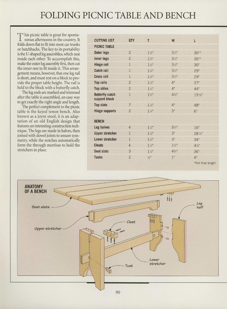
FOLDING PICNIC TABLE AND BENCHI
t
f his picnic table is great for sponta-I neous afternoons in the country. It
folds down flat to fit into most car trunlaor hatchbacks. The key to its portabilityis the U-shaped leg assemblies, which nestinside each other. To acccomplish this,make the outer leg assembly first, then cutthe inner one to fit inside it. This arran-gement means, however, that one leg railis short, and must rest on a block to pro-vide the proper table height. The rail isheld to the block with a butterfly catch.
The leg ends are marked and trimmedafter the table is assembled, an easy wayto get exactly the right angle and lengh.
The perfect complement to the picnictable is the keyed tenon bench. Alsoknown as a joynt stool, it is an adap-tation of an old English design thatfeatures an interesting construction tech-nique. The legs are made in halves, thenjoined with doweljoints to ensure sym-metry, while the notches automaticallyform the through mortises to hold thestretchers in olace.
CUTTII{G LIST
PICNIC TABTE
0uter legs
Inner legs
Hinge rail
Catch rail
Cross rail
Top rails
Top stiles
Butterfly catchsupport block
Top slats
Hinge supports
BENCH
Leg halves
Upper stretcher
Lower stretcher
Cleats
Seat slats
Tusks
OTY T
!Y, '
Ir/2'
LY,'
I% '
IY, '
LYo'
IYo'
IY4'
7/o'
I /4'
LY4'
I 'A'
Ir/o'
IY4'
!Yo'
V2u
w
3y,'?r/"1
3v,'3Y,'3Y2'
4',
4',
43/o'
L
36'*36u*
36'29',29',a 1 n
44-
19%',
48'
6 u
1 6 '
28r/r',
34',
4'/e',
36"4u*Not f inal length
IIIIttItIIIIIIIIIIIIIIIItI
z
z
1
I
1
Z
Z
1
Z
A t
?i l
4
1
1
4
z
5'/2',
3 u
?i l
I % '
43/o'
1 u
rI
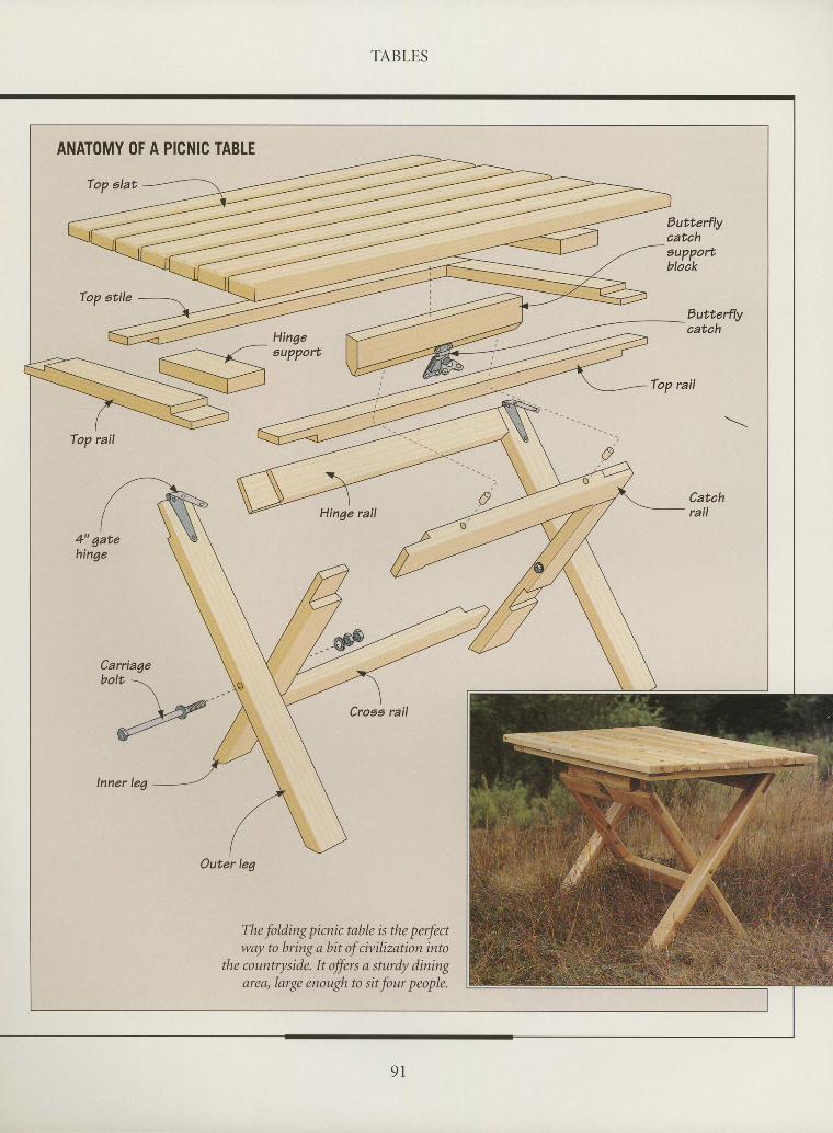
TABLES
II
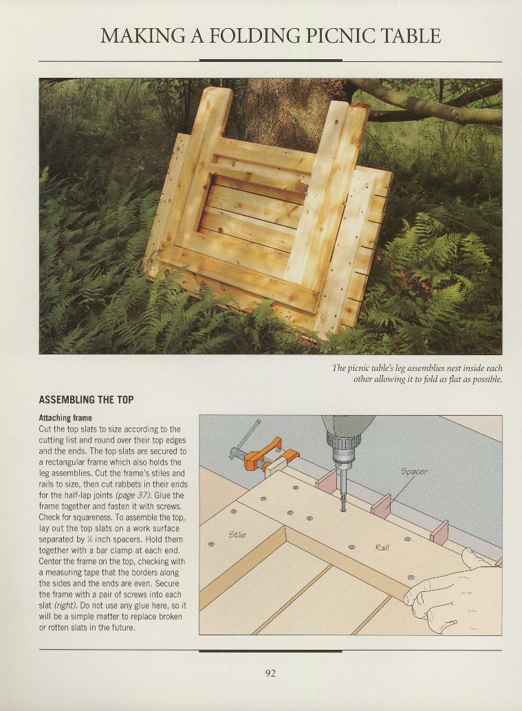
MAKING A FOLDING PICNIC TABLE
The picnic table's leg assentblies nest inside eachother allowing it to fold as flat as possible.
tIIIIIItItttI
I
I
tIIItIIItIIIItIII
ASSEMBLING THE T()P
Attaching frameCut the top slats to size accordrng to thecutt ing l ist and round over their top edgesand the ends. The top slats are secured toa rectangular frame which also holds theleg assemblies. Cut the frame's st i les andrai ls to size, then cut rabbets in their endsfor the half-lap joints (page 37). Glue theframe together and fasten it with screws.Check for squareness. To assemble the top,lay out the top slats on a work surfaceseparated by ln inch spacers. Hold themtogether w i th a bar c lamp a t each end.Center the frame on the top, checkrng witha measuring tape that the borders alongthe sides and the ends are even. Securethe frame with a oair of screws into eachslal (right). Do not use any glue here, so itwi l l be a simple matter to replace brokenor rotten slats in the future.
92
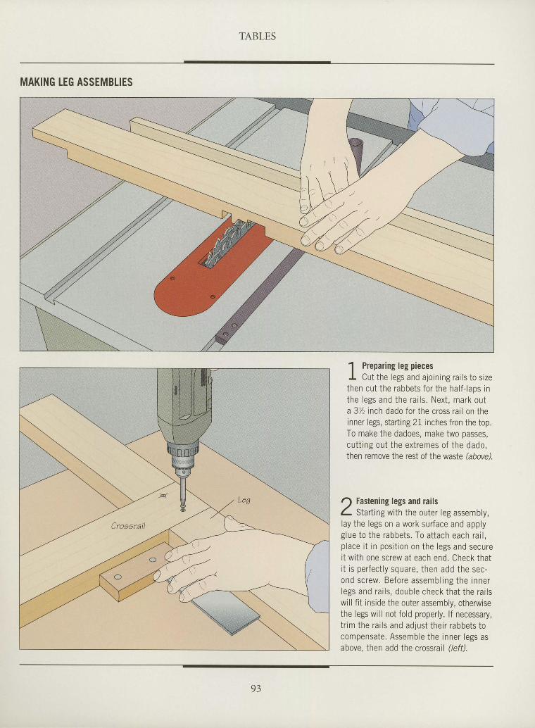
TABLES
MAKING IEG ASSEMBTIES
t
I
I
t
I
I
I
I
I
I
I
I
I
I
I
I
I
I
ttI
I
I
I
T
I
I
I
T
I
I
I
1 Preparing leg piecesI Cut the legs and ajoining rai ls to sizethen cut the rabbets for the half- laps inthe legs and the rai ls. Next, mark outa 3Yz inch dado for the cross rail on theinner legs, starting 21 rnches fron the top.To make the dadoes, make two passes,cutt ing out the extremes of the dado,then remove the rest of the waste hbovd.
Fastening legs and railsStart ing with the outer leg assembly,
lay the legs on a work surface and applyglue to the rabbets. To attach each rai l ,place i t in posi t ion on the legs and securei t with one screw at each end. Check thati t is perfect ly square, then add the sec-ond screw. Before assembl ing the innerlegs and rai ls, double check that the rai lswill fit inside the outer assembly, otherwisethe legs will not fold properly. lf necessary,tr im the rai ls and adjust their rabbets tocompensate. Assemble the inner legs asabove, then add the crossrail (/eff).
93
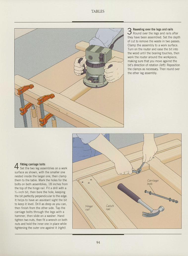
TABLES
I Rounding over the legs and rai ls<.
r - . f Round over the less and ra i ls af terthey have been assemi led. Set the depthof cut to remove the waste in two passes.C lamp the assemb ly t o a wo rk su r face .Turn on the router and ease the b i t in tothe wood unt i l the bear ing touches, thenwork the router around the workpiece,making sure that you move against thebit 's direction of rotation (/eft). Repositionthe clamps as necessary. Then round overthe other leg assembly.
I
I
I
I
I
T
T
I
T
I
t
I
T
I
I
I
I
T
I
I
I
I
I
t
I
I
I
I
I
I
I
I
Fitting carriage boltsSet the two les assembl ies on a work
sur face as shown, wi th the smal ler onenested ins ide the larger one, then c lampthem to the table. Mark the holes for thebol ts on both assembl ies, 18 inches f romthe ton n f t he h inpe ra i l F i t a d r i l l w i t h a/" - inch b i t , then bore the hole, keepingthe bit perfectly perpendicular to the edge.I t helps to have an assis tant s ight the b i tto keep i t level . Dr i l l as deep as you can,then f i n i sh f r om the o the r s i de . Tap theca r tage bo l t s t h rough the l egs w i th ahammer , t hen s l i de on a washe r . Handtighten two nuts, then fit a wrench on bothnuts and hold the inner one in p lace whi letightening the outer one against tI (right).
94
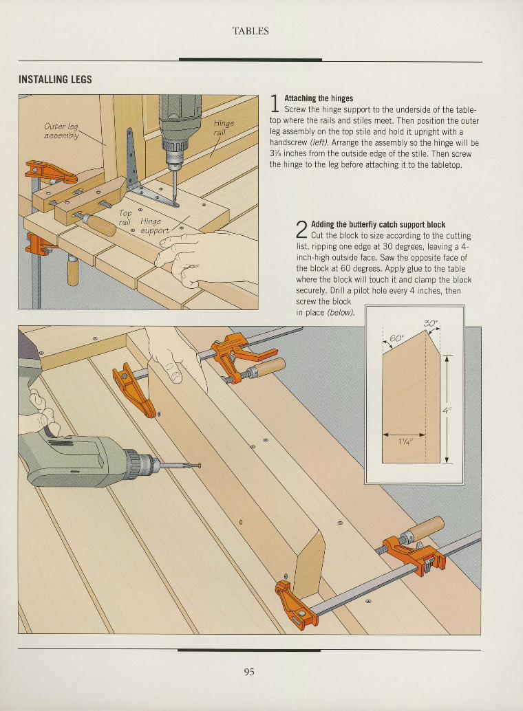
TABLES
I
I
I
t
rI
ttI
I
I
T
I
I
I
I
I
:
I
I
I
I
I
I
I
tI
I
T
I
I
I
INSTALLING LEGS' l Attaching the hingesI Screw the hinge support to the underside of the table-top where the rai ls and st i les meet. Then posit ion the outerleg assembly on the top st i le and hold i t upr ight with ahandscrew (left). Arrange the assembly so the hinge will be3% inches from the outside edge of the st i le. Then screwthe hinge to the leg before attaching i t to the tabletop.
Adding the butterfly catch support blockCut the block to size according to the cutt ing
l ist , r ipping one edge at 30 degrees, leaving a 4-inch-high outside face. Saw the opposite face ofthe block at 60 degrees. Apply glue to the tablewhere the block wi l l touch i t and clamp the blocksecurely. Dri l l a pi lot hole every 4 inches, thenscrew the b lockin place (below).
95
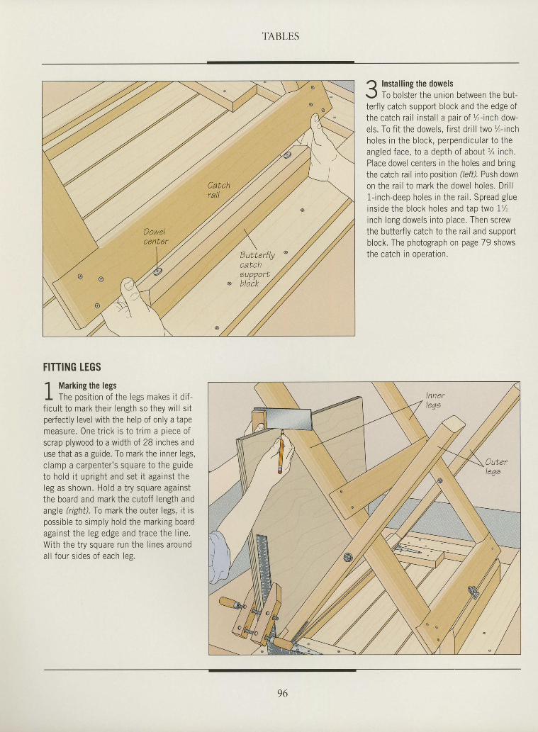
TABLES
? Installing the dowelsr-J To bolster the union between the but-terfly catch support block and the edge ofthe catch rai l instal l a pair of %-inch dow-els. To f i t the dowels, f i rst dr i l l two %-inchholes in the block, perpendicular to theangled face, to a depth of about %inch.Place dowel centers in the holes and bringthe catch rail into position (/eft). Push downon the rai l to mark the dowel holes. Dri l l1- inch-deep holes in the rai l . Spread glueinside the block holes and tap Iwo I ' / ,inch long dowels into place. Then screwthe butterfly catch to the rail and supportblock. The photograph on page 79 showsthe catch in operat ion.
I
I
I
t
I
I
I
I
I
I
I
I
I
I
I
I
I
I
I
I
I
I
I
I
I
I
I
I
I
I
T
I
FITTING IEGS
1 Marking the legsI The posit ion of the legs makes i t di f -f icul t to mark their length so they wi l l s i tperfectly level with the help of only a tapemeasure. 0ne tr ick rs to tr im a oiece ofscrap plywood to a width of 28 inches anduse that as a guide. To mark the inner legs,clamp a carpenter 's square to the guideto hold i t upr ight and set i t against theleg as shown. Hold a try square againstthe board and mark the cutoff length andangle (right). To mark the outer legs, it ispossible to simply hold the marking boardagainst the leg edge and trace the l ine.With the try square run the l ines aroundal l four sides of each les.
96
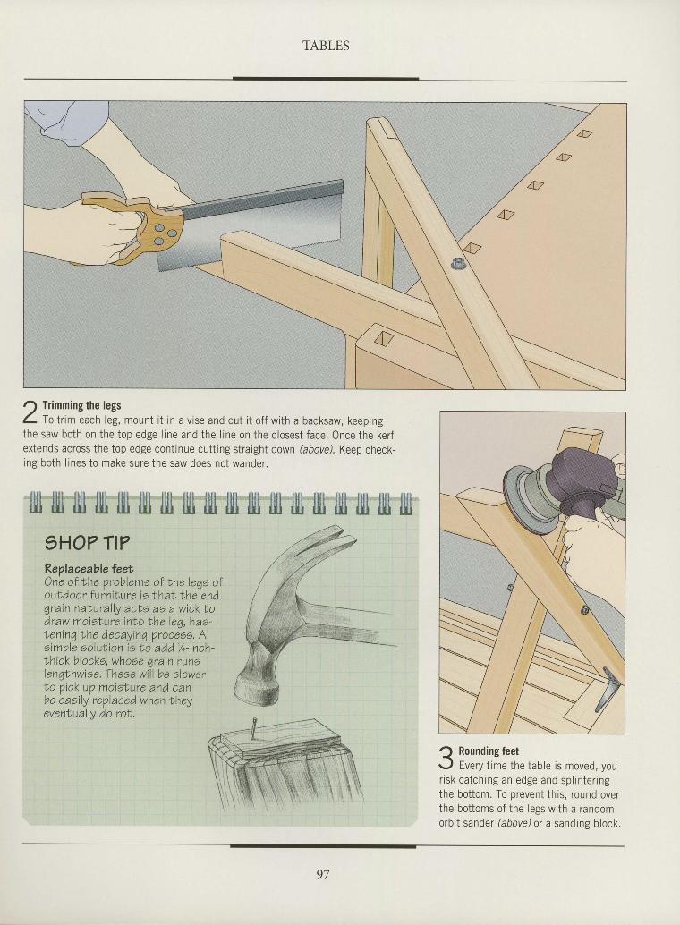
TABLES
I
I
I
I
T
I
I
I
I
I
ttI
I
T
I
T
I
rI
I
I
I
I
tI
I
I
I
I
I
t
! Trimming the legsC- f o tr im each leg, mount i t in a vise and cut i t of f with a backsaw, keepingthe saw both on the top edge l ine and the l rne on the closest face. Once the kerfextends across the top edge continue cutting straight down (above). Keep check-ing both l ines to make sure the saw does not wander.
ijll lllt fill lllt ljll illl tjll tjll jljt tlll itt llli llll ljll lllt tjll illl illt5HO7 Tt?Replaceable feetOne of Lhe probleme ol the leqe ofouLdoor furniNure ie Ihat, the endgrain natural ly ac|e as a wicktodraw moislure inNo lhe leg, hae-Nenin7lhe decayinq proceee. Aeimple soluNion is to add,1/o- inch-lhick blocks, whoee qrain runelenqthwioe. Theee wi l l be elowerNo pick up moisNure and canbe eaeily reVlaced when lheyeventually do roi.
Rounding feetEvery t ime the table is moved, you
risk catching an edge and spl inter ingthe bottom. To prevent thrs, round overthe bottoms of the legs with a randomorbit sander (above) or a sandine block.
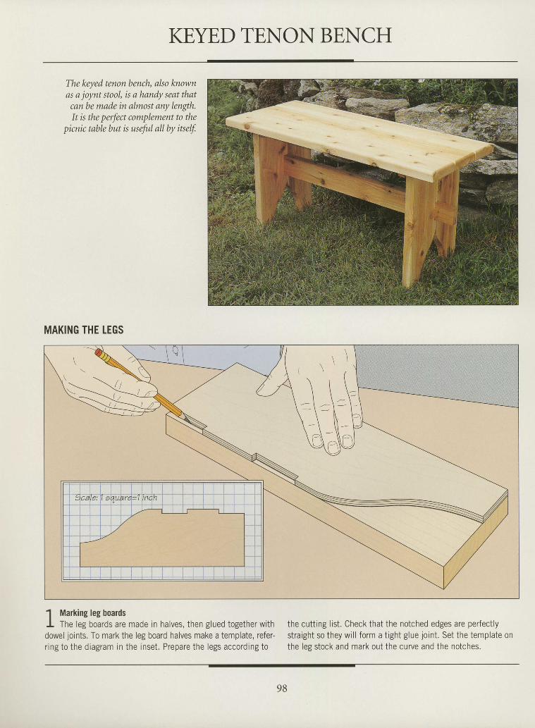
KEYED TENON BENCH
The keyed tenon bench, also knownas a joynt stool, is a handy seat that
canbe made in almost any length.It is the perfect complement to the
picnic table but is useful all by i*elf.
MAKING THE LEGS
1 Marking leg boardsI The leg boards are made in halves, then glued together withdowel joints. To mark the leg board halves make a template, refer-r ing to the diagram in the inset. Prepare the legs according to
the cutting list. Check that the notched edges are perfectlystraight so they wi l l form a t ight glue joint . Set the template onthe leg stock and mark out the curve and the notches.
I
I
I
t
tI
I
I
I
I
I
I
I
I
I
I
I
I
T
I
I
tI
I
I
I
I
I
I
I
I
I
98
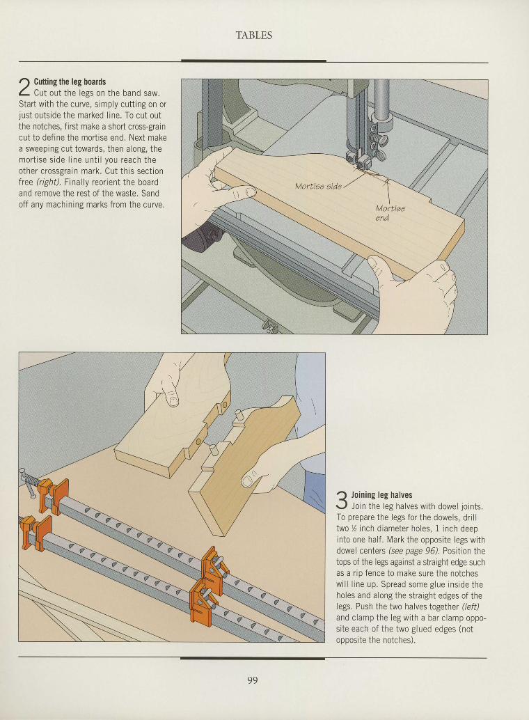
TABLES
tI
I
T
I
tI
I
I
I
I
I
tI
I
I
I
I
I
I
I
I
I
tI
ttI
I
I
I
I
r) Cutting the leg boardsL Cut out the less on the band saw.Start with the curve, s imply cuttrng on orjust outsrde the marked l ine. To cut outthe notches, first make a short cross-graincut to def ine the mort ise end. Next makea sweeping cut towards, then along, themor t i se s ide l ine un t i l you reach theother c rossgrarn mark . Cut th rs sec t ionfree (r ight) . Final ly reor ient the boardand remove the rest of the waste. Sandoff any machining marks from the curve.
Q Join ing leg halvesr- ,1 Join the leg halves wi th dowel jo ints .To prepare the legs for the dowels, dr i l ltwo y ' inch d iameter holes, 1 inch deepinto one hal f . Mark the opposi te legs wi thdowel centers (see page 96). Position thetops of the legs against a straight edge suchas a r ip fence to make sure the notchesw i l l l i ne up . Sp read some g lue i ns ide theholes and a long the st ra ight edges of thelegs. Push the two halves together (/eff)and c lamp the l eg w i th a ba r c l amp oppo -s i te each of the two g lued edges (notnnnns i t p i hp nn tehpc \
99
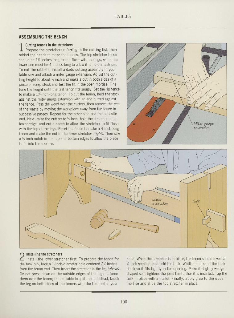
TABLES
ASSEMBTING THE BENCH
1 Cutting tenons in the stretchersI Prepare the stretchers referr ing to the cutt ing l ist , thenrabbet their ends to make the tenons. The top stretcher tenonshou ld be 1% inches longto end f lush w i th the legs , wh i le thelower one must be 4 inches long to al low i t to hold a tusk pin.To cu t the rabbets , ins ta l l a dado cu t t ing assembly in yourtable saw and attach a miter gauge extension. Adjust the cut-t ing height to about % inch and make a cut in both sides of apiece of scrap stock and test the f i t in the open mort ise. Finetune the height unt i l the tesi tenon f i ts snugly. Set the r ip fenceto make a 1%-inch-long tenon. To cut the tenon, hold ihe stockagainst the miter gauge extension with an end butted againstthe fence. Pass the wood over the cutters, then remove the restof the waste by moving the workpiece away from the fence insuccessive passes. Repeat for the other side and the oppositeend. Next, raise the cutters Io % inch, hold the stretcher on itslower edge, and cut a notch to al low the stretcher to f i t f lushwith the top of the legs. Reset the fence to make a 4- inch-longtenon and make the cut in the lower stretcher (right). Then sawa'/o-inch notch in the top and bottom edges to allow the pieceto f i t into the mort ise.
I
I
I
I
I
I
I
I
I
I
I
I
I
I
I
I
I
I
I
I
I
I
I
I
I
tI
I
I
I
I
I
o Installing the stretchersL lnstal l the lower stretcher f i rst . To prepare the tenon forthe tusk oin. bore a 1- inch-diameter hole ceniered 2% inchesfrom the tenon end. Then insert the stretcher in the leg (above).Do not press down on the outside edges of the legs to forcethem over the tenon; this is l iable to spl i t them. Instead, knockthe leg on both sides of the tenons with the the heel of your
hand. When the stretcher is in place, the tenon should reveal a%- inch semic i rc le to ho ld the tusk . Whi t t le and sand the tuskstock so i t f i ts t ight ly in the opening. Make i t s l ight ly wedge-shaped so i t t ightens the joint the further i t is inserted. Tap thetusk in p lace w i th a mal le t . F ina l l y , app ly g lue to the uppermort ise and slrde the too stretcher in olace.
Loweratretcher
r00
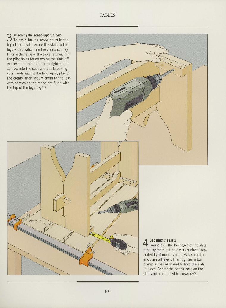
TABLES
t
I
I
t
I
tI
I
I
I
I
I
tI
I
I
tI
I
I
I
I
tI
I
I
I
I
I
I
I
I
I Attaching the seat-support cleats<'
r- ,1 To avoid havins screw holes in thetoo of the seat. seJure the slats to thelegs with cleats. Tr im the cleats so theyf i t on ei ther side of the top stretcher. Dri l lthe pi lot holes for at taching the slats offcen ter to make i t eas ie r to t igh ten thescrews into the seat without knockingyour hands against the legs. Apply glue tothe c lea ts , then secure them to the legswith screws so the str ips are f lush withthe top of Ihe legs (right).
Securing the slatsRound over the top edges of the slats,
then lay them out on a work surface, sep-arated by %-inch spacers. Make sure theends are a l l even, then t igh ten a barclamp across each end to hold the slatsin place. Center the bench base on theslats and secure it with screws //eff).
1 0 1
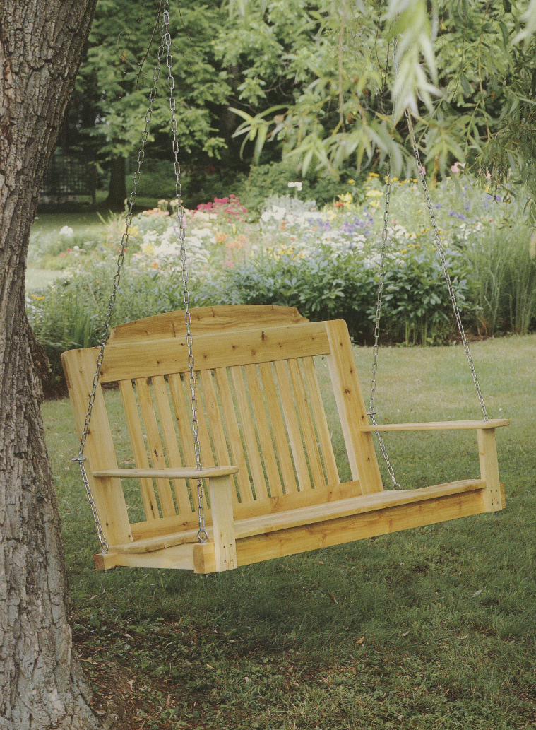
bt
#Tr-rl
I
' t,f^:. t r
I
r \ ,
I
tl ,
"r
ffi\3\_tit
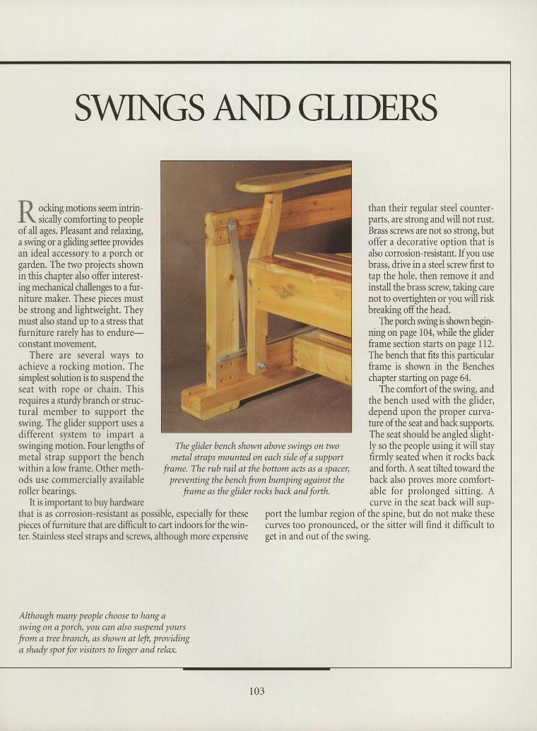
tI
IIIIItItIIIItIIIIIIIIIIIII
than their regular steel counter-parts, are strong and will not rust.Brass screws are not so strong, butoffer a decorative option that isalso corrosion-resistant. If you usebrass, drive in a steel screw first totap the hole, then remoYe it andinstall the brass screw taking carenot to overtighten or you will riskbreaking offthe head.
The porch swing is shown begin-ning on page 104, while the gliderframe section starts on page II2.The bench that fits this particularframe is shown in the Bencheschapter starting on page 64.
The comfort of the swing, andthe bench used with the glideqdepend upon the proper curva-ture ofthe seat and back supports.The seat shouldbe angled slight-ly so the people using it will stayfirmly seated when it rocks backand forth. A seat tilted toward theback also proves more comfort-able for prolonged sitting. Acurve in the seat back will sup-
Although many people choose to hang aswing on a porch, you can also suspend yours
from a treebranch, as shown atleft, providinga shady spot for visitors to linger and relax.
II
SWINGS AI.{D GLIDERS
p o.kittg-otionsseemintrin-I\ sically comforting to peopleofall ages. Pleasant and relaxing,a swing or a gliding settee providesair ideal accessory to a porch orgarden. The two projects shownin this chapter also offer interest-ing mecJranical challenges to a frr-niture maker. These pieces mustbe strong and lightweight. Theymust also stand up to a stress thatfurniture rarely has to endure-constant movement.
There are several wavs toachieve a rocking motion. Thesimplest solution is to suspend ttreseat with rope or chain. Thisrequires a sturdybranch or struc-tural member to support theswing. The glider support uses adifferent system to impart aswinging motion. Four lengths ofmetal strap support the benchwithin a low frame. Other meth-ods use commercially availableroller bearings.
It is important to buyhardwarethat is as corrosion-resistant as possible, especially for thesepieces of furniture that are difficult to cart indoors for the win-ter. Stainless steel straps and screws, although more expensive
The glider bench shown above swings on twometal straps mounted on each side of a supPort
frame. The rub rail at the bottom acts as a spacer,preventingthebench ftom bumping against the
frame as the glider roclcs back and forth.
port the lumbar region of the spine, but do not make thesecurves too pronounced, or the sitter will find it difficult toget in and out of the swing.
103
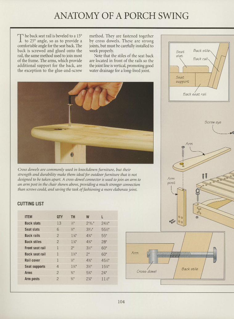
ANATOMYOFAPORCH SWINGI
I
tlt h. back seat rail is beveled to a l5oI to 25" angle, so as to provide a
comfortable angle for the seat back. Theback is screwed and glued onto therail, the same method used to join mostof the frame. The arms, which provideadditional support for the back, arethe exception to the glue-and-screw
method. They are fastened togetherby cross dowels. These are strongjoints, but must be carefully installed towork properly.
Note that the stiles of the seat backare located in front of the rails so thethe joint line is vertical, promoting goodwater drainage for a long-lived joint.
Cross dowels are commonly used in knockdown furniture, but theirstrength and durability make them ideal for outdoor furniture that is notdesigned to be taken apart. A cross-dowel connector is used to join an arm toan arm post in the chair shown above, providing a much stronger connectionthan screws could, and saving the task of fashioning a more elaborate joint.
CUTTING LIST
ITEM
Back slats
Seat slats
Back rails
Back stiles
Front seat rail
Back seat rail
Rail cover
Seat supports
Arms
Arm posts
OTY
6
z
z
I'I
i
4
z
Z
TH%'-/4
t% '
It/a'
Z
I% '
Yo'
I%'
%'
%'
W L2r5Ao" 24Y4'
3%"" 55Yr'
A%', 55"
4%', 28',
3%', 60'
2u 60'
4%', 45Y2'.
3Yr' t5%'
5%', 24',
2%' T I%'
geat Dack attle
alat
Eack eeat ratl
Arm
I
I
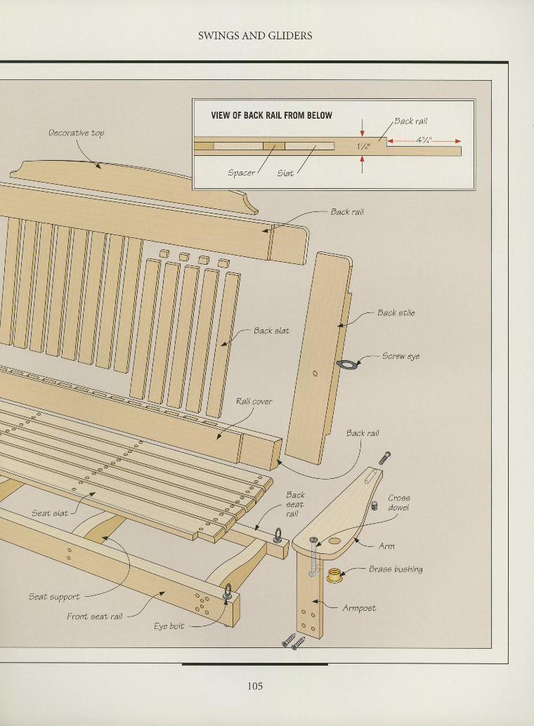
II SWINGS AND GLIDERS
Eack alat
Rail cover
I
I
I
I
I
I
I
I
I
VIEW ()F BACK RAIL FR()M BELOW
g- Draae buehinq
Front aeat rail
t0s
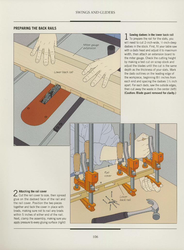
SWINGS AND GLIDERS
PREPARING THE BACK RAITS
Attaching the rail coverCut the rail cover to size, then spread
g lue on the dadoed face o f the ra i l andthe rai l cover. Posit ion the two piecestogether and tack the cover in place withbrads, making sure not to nai l any bradswithin 5 inches of ei ther end of the nai l .Next, clamp the assembly, making sure youapply pressure to every gluingsurface (right).
1 Sawing dadoes in the lower back railI To prepare the rail for the slats, youwil l need to cut 2- inch-wide, %-inch-deepdadoes in the stock. First, fit your table sawwith a dado head and adjust it to maximumwidth, then attach an extension board tothe miter gauge. Check the cutt ing heightby making a test cut on scrap stock andadjust the blades unt i l the cut is the samedepth as the thickness of your slats. Markthe dado out l ines on the leading edge ofthe workpiece, beginning 8% inches fromeach end and spacing the dadoes 1% inchapart. For each dado, saw the outside edges,then cut away the waste in the center (/eff).(Caution: Blade guard removed for clarity.)
I
I
I
I
I
I
I
I
I
I
I
I
I
I
I
I
I
I
I
I
tI
I
I
I
I
I
I
I
I
I
I
[ \ X\ u Lower
\Xbackrai l
// \
106
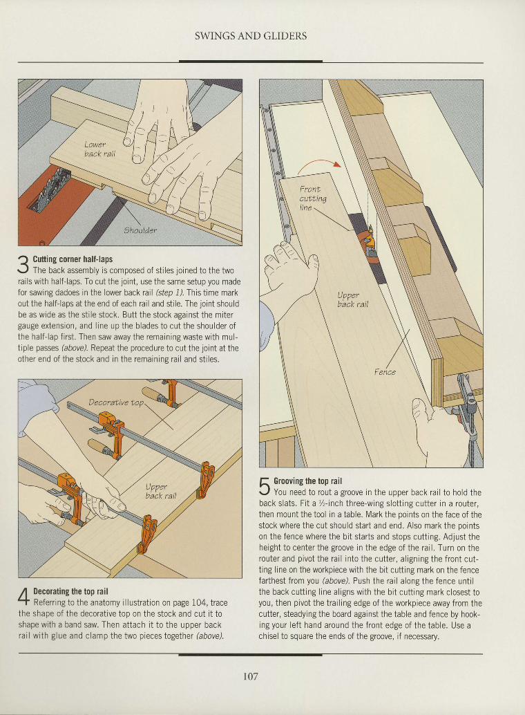
SWINGS AND GLIDERS
I
I
ttI
tI
I
I
I
I
I
I
I
I
I
I
tI
rI
I
I
I
I
I
I
I
I
I
tI
Cutting corner half-lapsThe back assembly is composed of stiles joined to the two
rails with half-laps. To cut the joint, use the same setup you madefor sawing dadoes in the lower back rail (step 1) This time markout the half-laps at the end of each rail and stile. The joint shouldbe as wide as the stile stock. Butt the stock against the mitergauge extension, and l ine up the blades to cut the shoulder ofthe half-lap first. Then saw away the remaining waste with mul-tiple passes (above). Repeat the procedure to cut the joint at theother end of the stock and in the remainins rai l and st i les.
Decorating the top railReferring to the anatomy illustration on page 104, trace
the shape of the decorative top on the stock and cut it toshapewith a band saw. Then attach i t to the upper backrai l with glue and clamp the two pieces together (above).
f, Grooving the top railr./ You need to rout a groove in the upper back rail to hold theback slats. Fi t a %-inch three-wing slot t ing cutter in a router,then mount the tool in a table. Mark the ooints on the face of thestock where the cut should start and end. Also mark the pointson the fence where the bit starts and stops cutting. Adjust theheight to center the groove in the edge of the rai l . Turn on therouter and pivot the rai l into the cutter, al igning the front cut-ting line on the workpiece with the bit cutting mark on the fencefarthest from you (abovd. Push the rail along the fence untilthe back cutt ing l ine al igns with the bi t cutt ing mark closest toyou, then pivot the trailing edge of the workpiece away from thecutter, steadying the board against the table and fence by hook-ing your lef t hand around the front edge of the table. Use achisel to square the ends of the groove, if necessary.
r07
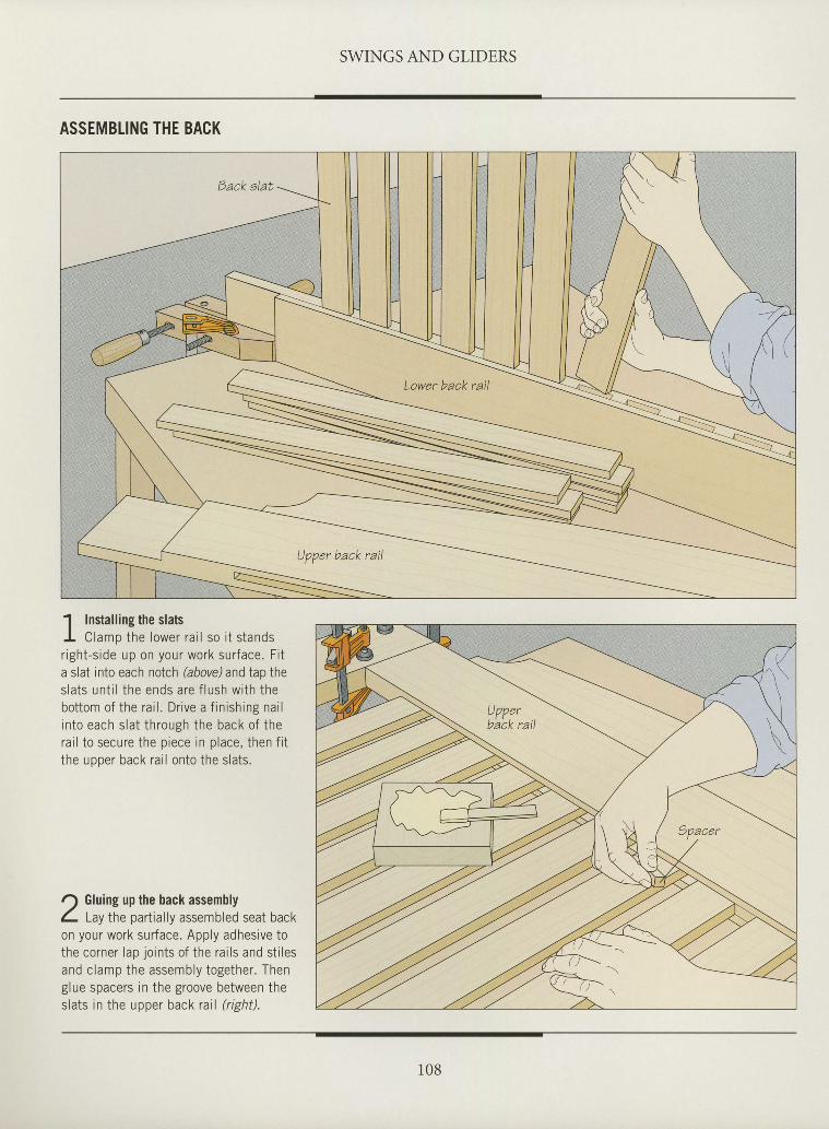
SWINGS AND GLIDERS
ASSEMBTING THE BACK
I
I
I
I
I
I
I
I
I
I
I
I
I
I
I
tI
I
I
tI
I
I
I
I
I
I
I
I
I
I
I
1 Installing the slatsI C lamp the lower ra i l so i t s tandsright-side up on your work surface. Fi ta slat into each notch (above) and tap thes la ts un t i l the ends are f lush w i th thebottom of the rai l . Dr ive a f in ishing nai linto each slat through the back of therai l to secure the piece in place, then f i tthe uooer back rai l onto the slats.
Gluing up the back assemblyLay the part ial ly assembled seat back
on your work surface. Apply adhesive tothe corner Iap joints of the rai ls and st i lesand clamp the assembly together. Thenglue spacers in the groove between theslats in the upper back rai l ( r ight) .
r08
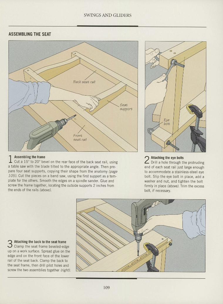
SWINGS AND GLIDERS
I
I
I
t
I
I
I
I
t
t
I
I
I
I
I
I
I
I
I
I
I
I
I
I
I
I
I
tI
I
I
I
ASSEMBTING THE SEAT
1 Assembling the frameI Cut a 15" to 20 'beve l on the rear face o f the back seat ra i l , us inga tab le saw wi th the b lade t i l ted to the appropr ia te ang le . Then pre-pare four seat supports, copying their shape from the anatomy (page105). CUI the pieces on a band saw, using the f i rst support as a tem-plate for the others. Smooth the edges on a spindle sander. Glue andscrew the frame together, locat ing the outside supports 2 inches fromthe ends of the rails (abovd.
Q Attaching the back to the seat framer-, f Clamp the seat frame beveled-edgeup on a work surface. Spread glue on theedge and on the front face of the lowerrai l of the seat back. Clamp the back tothe seat frame, then dr i l l p i lot holes andscrew the two assemblies together (right).
r) Attaching the eye bolts1 Ort l l a hole through the protrudingend of each seat rar l just large enoughto accommodate a stainless-steel eyebo l t . S l ip the eye bo l t in p lace , add awasher and nu t , and t igh ten the bo l tfirmly in place (above). Trim the excessbolt, if necessary.
109
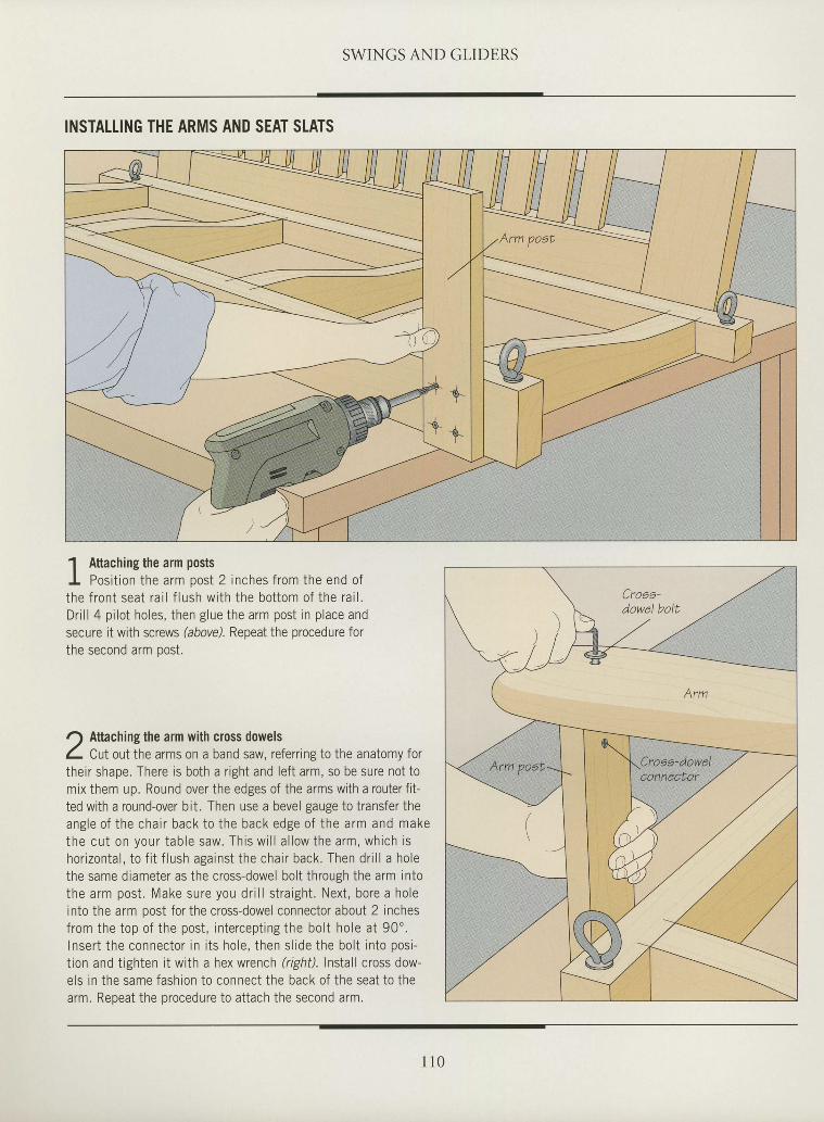
SWINGS AND GLIDERS
INSTALLING THE ARMS AND SEAT STATS
I
I
I
I
I
I
I
I
I
I
I
I
I
I
I
tII
I
t
I
I
I
I
I
I
I
I
I
I
I
I
{ ,' s
1 Attaching the arm postsI Posit ion the arm oost 2 inches from the end ofthe f ron t sea t ra i l f lush w i th the bo t tom o f the ra i l .Dr i l l 4 pi lot holes, then glue the arm post in place andsecure it with screws (abovd. Repeat the procedure forthe second arm oost.
r) Aftaching the arm with cross dowelsL Cutout the arms on a band saw, referring to the anatomy fortheir shape. There is both a r ight and lef t arm, so be sure not tomix them up. Round over the edges of the arms with a routerf i t -ted with a round-over bit. Then use a bevel gauge to transfer theang le o f the cha i r back to the back edge o f the arm and makethe cu t on your tab le saw. Th is w i l l a l low the arm, wh ich ishor izon ta l , to f i t f lush aga ins t the cha i r back . Then dr i l l a ho lethe same diameter as the cross-dowel bolt through the arm intothe arm pos t . Make sure you dr i l l s t ra igh t . Nex t , bore a ho leinto the arm post for the cross-dowel connector about 2 inchesfrom the top of the post, intercept ing the bolt hole at 90".Inser t the connector in i t s ho le , then s l ide the bo l t in to pos i -tion and tighten it with a hex wrench (righil. lnslall cross dow-els in the same fashion to connect the back of the seat to thearm. Repeat the procedure to attach the second arm.
1 1 0
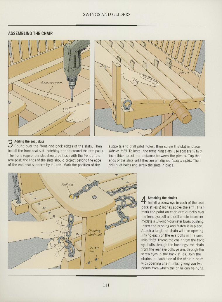
SWINGS AND GLIDERS
IIItIIIII
tII
I
I
I
tI
I
I
tI
I
I
I
T
I
I
tIII
I
ASSEMBLING THE CHAIR
a Addine the seat slats<'
r . , l Round over the f ront and back edges of the s lats . Theninsta l l the f ront seat s lat , notching i t to f i t around the arm posts.The f ront edge of the s lat should be f lush wi th the f ront of thearm post ; the ends of the s lats should pro ject beyond the edgeof the end seat supports by I inch. Mark the posi t ion of the
suppo r t s and d r i l l p i l o t ho les , t hen sc rew the s la t i n p lace(above, lefi l .fo install the remaining slats, use spacers r/eIo'/o
i nch th i ck t o se t t he d i s tance be tween the p ieces . Tap theends of the slats unti l they are all aligned (above, right).Thend r i l l p i l o t ho les and sc rew the s la t s i n p lace .
Aftaching the chainsInstall a screw eye in each of the seat
back st i les 2 inches above the arm. Thenmark the point on each arm di rect ly overthe front eye bolt and dril l a hole to accom-modate a l%- inch-diameter brass bushing.Inser t the bushing and fasten i t in p lace.At tach a length of chain wi th an openingl i nk t o each o f t he eye bo l t s i n t he sea trails (lefi l . Thread the chain from the fronteye bol ts through the bushings; the chainfrom the rear eye bolts passes through thesc rew eyes i n t he back s t i l es . Jo in t hecha ins on each s ide o f t he cha i r i n pa i r sw i th open ing cha in l i nks , g i v i ng you twopo in t s f r om wh ich the cha i r can be hung .
Openina' chain llnk
9creweve l
t lt M l
- { l
l l l
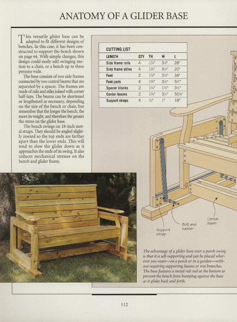
ANATOMY OF A GLIDER BASEII
f his versatile glider base can beI adapted to fit different designs of
benches. In this case, it has been con-structed to support the bench shownon page 64. With simple changes, thisdesign could easily add swinging mo-tion to a chair, or a bench up to threepersons wide.
The base consists of two side fiamesconnected by two central beams that areseparated by a spacer. The frames aremade of rails and stiles joined with cornerhalf-laps. The beams can be shortenedor lengthened as necessary, dependingon the size of the bench or chair, butremember that the longer the bench, themore its weight, and therefore the greaterthe stress on the glider base.
The bench swings on 18-inch met-al straps. They should be angled slight-ly inward so the top ends are fartherapart than the lower ends. This willtend to slow the glider down as itapproaches the ends of its swing. It alsoreduces mechanical stresses on thebench and glider frame.
I
Eolt andwaaher
Centerbeam I
I
I
I
I
I
9upportetraP
The advantage of a glider base over a porch swingis that it is self-supporting and can be placed wher-ever you want-on a porch or in a garden-with-out requiring supportingbeams or tree branches.The base features a metal rub rail at the bottom toprevent the bench from bumping against the baseas it glides back and forth.
CUTTING LIST
Foot pads 4 I%' 3'/r' 5'/o'
Center beams 2 I%' 3'/,' 50%'
Support straps
I
I
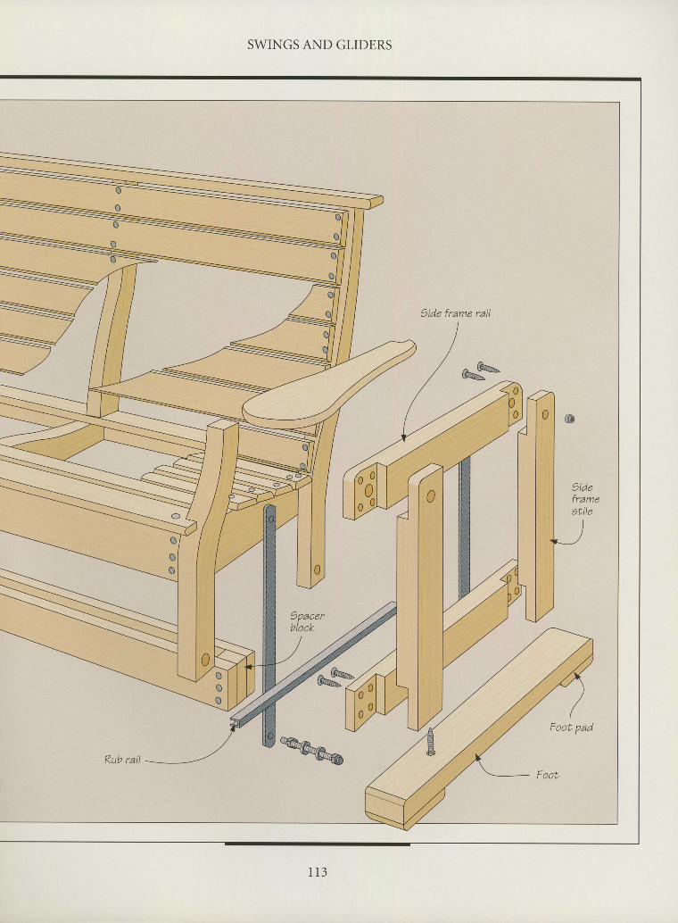
II SWINGS AND GLIDERS
)ide frame rail
#
I
IIIIIt
1 1 3
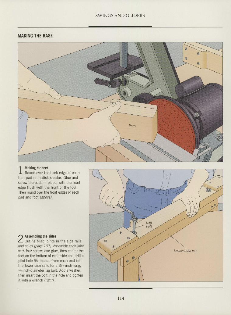
SWINGS AND GLIDERS
MAKING THE BASE
tIIIIIII
I
I
I
I
I
I
I
I
I
I
I
I
I
tI
I
I
I
I
I
I
I
I
I
1 Making the feetI Round over the back edge of eachfoo t pad on a d isk sander . G lue andscrew the pads in place, with the frontedge f lush with the front of the foot.Then round over the front edses of eachpad and Ioot (above).
r) Assembling the sidesL Cu t ha l f - l ao i o i n t s i n t he s i de ra i l sand sti les (page 107). Assemble each joint
wi th four screws and g lue, then center thefeet on the bot tom of each s ide and dr i l l ap i l o t ho le 5% inches f rom each end i n tothe l ower s i de ra i l s f o r a 3%- inch - l ong ,%-inch-diameter lag bol t . Add a washer,then inser t the bol t in the hole and t ightenit with a wrench (rishil.
Lower eide rail
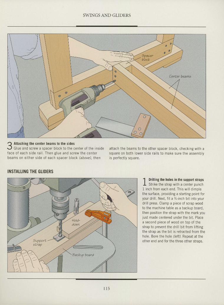
SWINGS AND GLIDERS
IIIIIIIIIItIIIIIIIIIIIIIIIIIIIII
Q Attaching the center beams to the sidess, l Glue and screw a spacer block to the center of the insidef a c e o f e a c h s i d e r a i l . T h e n g l u e a n d s c r e w t h e c e n t e rbeams on e i ther s ide o f each spacer b lock (above) . then
INSTATLING THE GLIDERS
attach the beams to the other spacer block, checking with asquare on bo th lower s ide ra i l s to make sure the assemblyi c n p r f p n t l v e n r 2 r a
1 Drill ing the holes in the support strapsI Str ike the strap with a center punchI inch f rom each end. Th is w i l l d imp lethe surface, providing a start ing point foryour dr i l l . Next, f i t a %-inch bi t into yourdr i l l press. Clamp a piece of scrap woodto the machine table as a backup board,then posit ion the strap with the mark youjust made centered under the bi t . Placea second piece of wood on top of thestrap to prevent the dr i l l b i t f rom l i f t ingthe strap as the bi t is retracted from thehole. Bore the hole (/eff). Repeat at theother end and for the three other straos.
l l 5
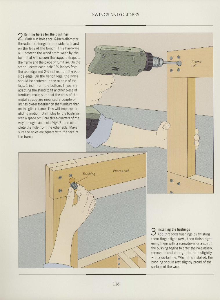
SWINGS AND GLIDERS
r) Dri l l ing holes for the bushings1 l t tarV, out holes for %-inch-diameterth readed bush ings on the s ide ra i l s andon the legs of the bench. This hardwarewil l protect the wood from wear by thebolts that will secure the support straps tothe frame and the piece of furniture. 0n thestand, locate each hole 1% inches fromthe top edge and 21/oinches from the out-side edge. On the bench legs, the holesshould be centered in the middle of thelegs, 1 inch from the bottom. l f you areadapting the stand to fit another piece offurniture, make sure that the ends of themetal straps are mounted a couple ofinches closer together on the furniture thanon the gl ider frame. This wi l l improve thegl iding motion. Dri l l holes for the bushingswith a spade bit. Bore three-quarters of theway through each hole (right),Ihen com-plete the hole from the other srde. Makesure the holes are souare with the face ofthe frame.
IItIIIIIIIIIIItIIIIaI
I
I
I
I
tI
I
I
tII
? Instal l ing the bushings\, , Add threaded bushings by twist ingthem finger tighl (left), then finish tight-ening them with a screwdriver or a coin. l fthe bushing begins to enter the hole askew,remove i t and en la rge the ho le s l igh t lywith a rat{ai l f i le. When i t is instal led, thebushing should rest s l ight ly proud of thesurface of the wood.
l l 6
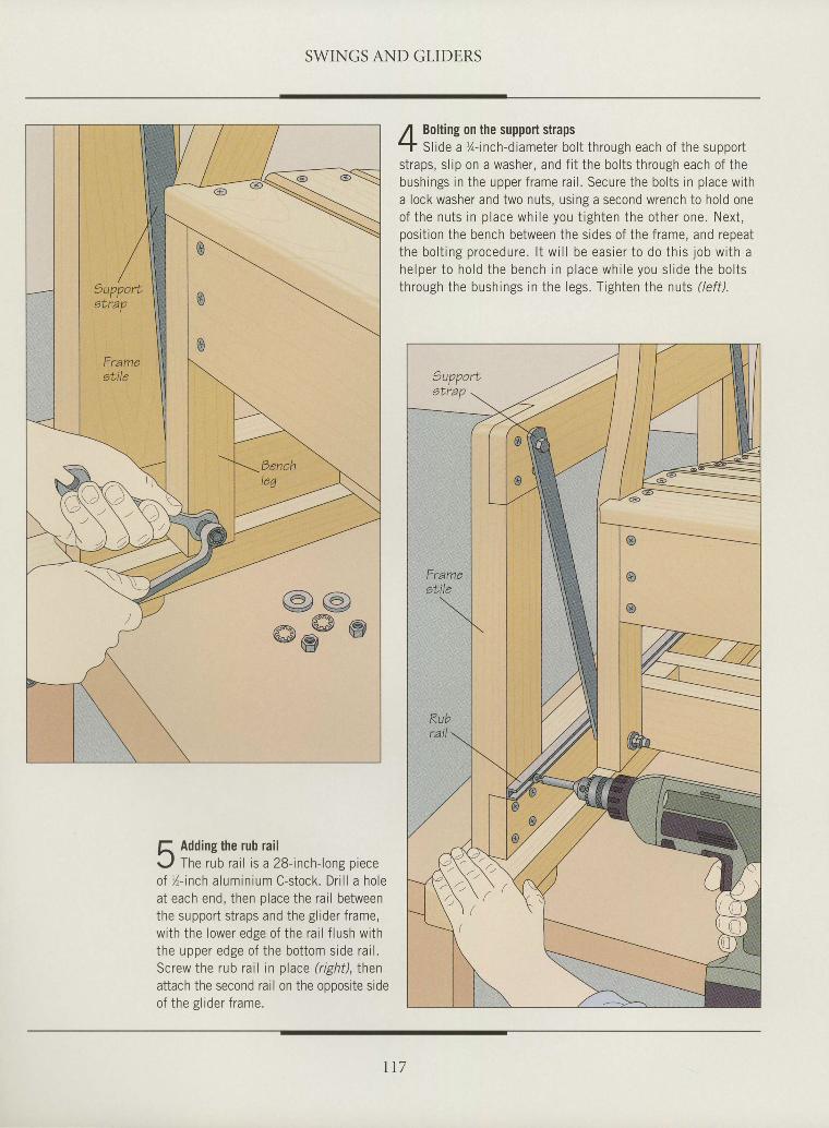
SWINGS AND GLIDERS
tIItItIIIIIIIIIIIIIIIIItIIIIIIIt
f, Adding the rub railr . , / The rub ra i l is a 28- inch- long p ieceof / , - inch a luminium C-stock. Dr i l l a holeat each end, then p lace the ra i l betweenthe support s t raps and the g l ider f rame,wi th the lower edge of the ra i l f lush wi ththe upper edge of the bot tom s ide ra i l .Screw the rub ra i l in p lace ( r ight) , thenattach the second rail on the oooosite sideof the s l ider f rame.
Bolting on the support strapsSl ide a %- inch-diameter bol t through each of the support
straps, s l ip on a washer, and f i t the bolts through each of thebushings in the upper frame rai l . Secure the bolts in place witha lock washer and two nuts, using a second wrench to hold oneof the nu ts in p lace wh i le you t igh ten the o ther one. Nex t ,posi t ion the bench between the sides of the frame, and repeatthe bo l t ing procedure . l t w i l l be eas ie r to do th is job w i th ah e l p e r t o h o l d t h e b e n c h i n p l a c e w h i l e y o u s l i d e t h e b o l t sthrough the bushings in the legs. Tighten the nuts ( /ef f) .9upport
etrap
Frameatile
\IJ
o
o
t 1 7
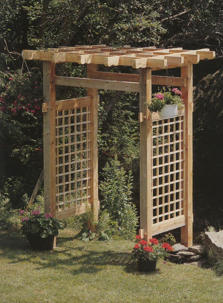
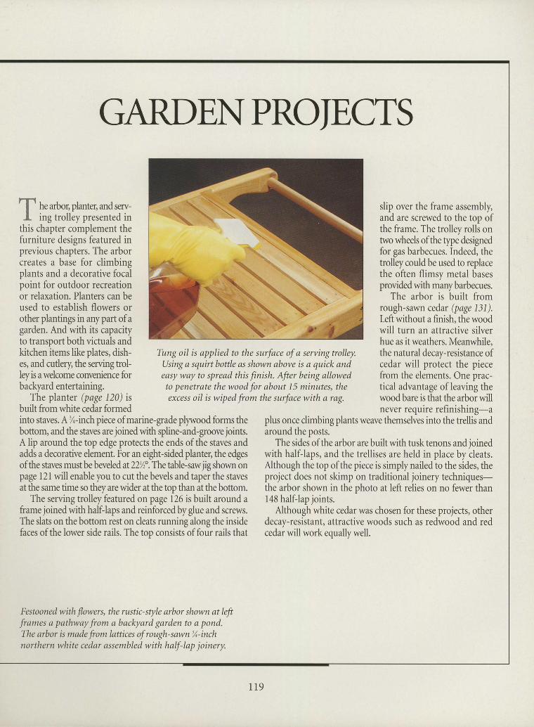
tt
IIIIIItIIIIIIIIIIIIItIIItt
II
GARDENPROIE,CTS
he arbor, planter, andserv-ing trolley presented in
this chapter complement thefurniture designs featured inprevious chapters. The arborcreates a base for climbingplants and a decorative focalpoint for outdoor recreationor relaxation. Planters can beused to establish flowers orother plantings in anypart of agard.en. And with its capacityto transport both victuals andkitchen items like plates, dish-es, and cutlery the serving trol-leyis awelcome convenience forbackyard entertaining.
The planter (page 120) isbuilt from white cedar formed
Tung oil is applied to the surface of a servingtrolley.Using a squirt bottle as shown above is a quick andeasy way to spread this finish. After being allowedto Penetrate the wood for about 15 minutes, theexcess oil is wiped from the surface with a rag.
slip over the frame assembly,and are screwed to the top ofthe frame. The trolley rolls ontwo wheels of the type designedfor gas barbecues. Indeed, thetrolley could be used to replacethe often flimsy metal basesprovided with many barbecues.
The arbor is built fromrough-sawn cedar (page 131).leftwithout a finish, the woodwill turn an attractive silverhue as itweathers. Meanwhile,the natural decay-resistance ofcedar will protect the piecefrom the elements. One prac-tical advantage of leaving thewood bare is that the arbor willnever require refinishing-a
into staves. A %-inch piece of marine-grade plywood forms thebottom, and the staves are joined with spline-and-groove joints.A lip around the top edge protects the ends ofthe staves andadds a decorative element. For an eight-sided planter, the edgesof the staves must be beveled at 22/z'.TlT table-saw jig shown onpage I2I will enable you to cut the bevels and taper the stavesat the same time so they are wider at the top than at the bottom.
The serving trolley featured on page 126 is built around aframe joined with halfJaps and reinforced by glue and screws.The slats on the bottom rest on cleats running along the insidefaces of the lower side rails. The top consists of four rails that
plus once climbing plants weave themselves into the trellis andaround the posts.
The sides of the arbor are built with tusk tenons and ioinedwith half-laps, and the trellises are held in place by ileats.Although the top of the piece is simply nailed to the sides, theproject does not skimp on traditional joinery techniques-the arbor shown in the photo at left relies on no fewer than148 halfJap joints.
Although white cedar was chosen for these projects, otherdecay-resistant, attractive woods such as redwood and redcedar will work equally well.
Festooned with flowers, the rustic-style arbor shown at leftframes a pathway from a backyard garden to a pond.The arbor is made from lattices of rough-sawn %-inchnorthern white cedar assembled with half-lap joinery.
1 1 9
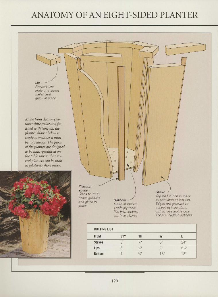
ANATOMY OF AN E,IGHT-SIDED PLANTERIIIIIIIIIIIIII
tIttIII
I
tIIIIIIII
ende of etavee;nailed andqlued in place
Made from decay-resis-tant white cedar and fn-ished with tung oil, theplanter shown below isready to weather a num-ber of seasons. The partsof the planter are designedto be mass-produced onthe table saw so that sev-eral planters cqn be buihin relatively short order.
Plywoodapline'ized to fit ingtave 1roovesand 4lued inplace
Stave
EottomTapered 2 inchea widerat top than at bottan.Edqee are qrooved toaccept eplinee; dadocut acrooa inetde faceaccommodateg bottom
Made of marine-4rade plywood;fita into dadoeacut into atave7
CUTTING LIST
ITEM OTY TH w L
Staves 8 3,4', 6" 24',
Lips 8 % ' 2', 6"1',
IBottom 3/o' 1B' 1 8 "
t20
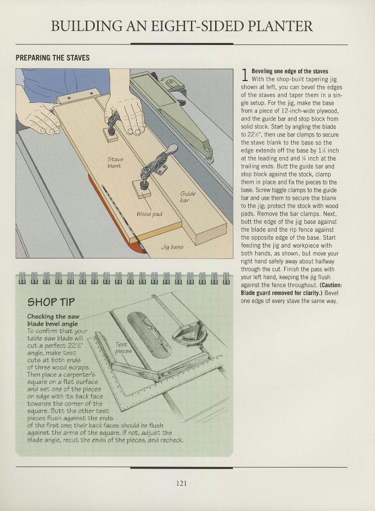
BUILDING AN EIGHT-SIDE,D PLANTERIIItIIIIIIItI
tIIIIIIIIIIIIIIIIII
PREPARING THE STAVES
1HO? TI?Checkingthe sawblade bevel angleTo confirm trhat, your
'l Beveling one edge of the stavesI W i t h t h e s h o p - b u i l t t a p e r i n g j r gshown at lef t , you can bevel the edgesn f t hc s taves and tane r t hem in a s i n -s le setr ro. For the i ip . make the basei v i ! , i v
J ' b ,
i i i !
f rom a p iece of l2- inch-wide p lywood.and the guide bar and stop b lock f romsol id s tock. Star t by angl ing the b ladel a 2 2 r / " t h p n r r c p h e r n l e__, _,_mps r0 securethe s tave b lank to t he base so theedge ex tends o f f t he base by 1Z i ncha t t he l ead ing end and % inch a t t het ra i l i ng ends . Bu t t t he gu ide ba r andstop b lock against the stock, c lampthem in p lace and f ix the p ieces to thebase. Screw toggle clamps to the guidebar and use them to secure the b lankto the i ip ' nrotect the stock wi th woodpads . Remove the ba r c l amps . Nex t ,h i l i t t h p p d s p n f i h A i i o h . - ^ - ^ - i n . +. . , - I ' o u d ) c d B d i l r J L
t he b lade and the r i p f ence aga ins tthe opposi te edge of the base. Star tf eed ing the l i g and workp iece w i thboth hands, as shown, but move yourr ight hand safe ly away about hal fwaythrough the cut . F in ish the pass wi thyour le f t hand, keeping the j ig f lushagainst the fence throughout . (Caut ion:
Blade guard removed for c lar i ty . ) Bevelone edge of every stave the same way.
'llt l{l ilj llll lllt {1il lll lllj ull t]l] illt illj iljj filt lllt ljll llil lllj
\''t''"''
and eeN one of the Vieceoon edqe wiLh i le back f acet owards Lhe corner of Iheequare, butl the olher Lest,p iecee f luah againel the endsof Nhe fireN one: Lheir back faces should be flueha4ainel Lhe arme of the equare. l f noI, adjuel Lheblade anqle, reculf ,he ende ol lhe pieceo, and recheck.
t21
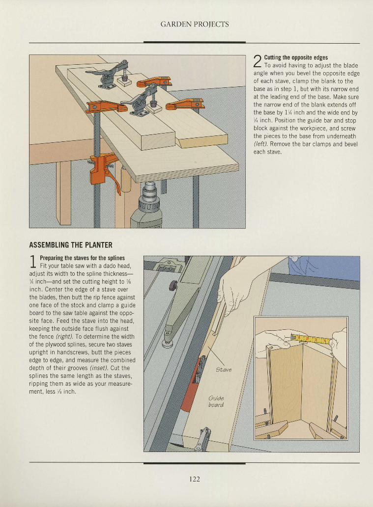
GARDEN PROTECTS
r) Cutting the opposite edgesL to avo id hav ing to ad jus t t he b ladeangle when you bevel the opposi te edgeo f each s tave , c l amp the b lank to t hebase as in s tep 1, but wi th i ts narrow endat the leading end of the base. Make surethe narrow end of the b lank extends of fthe base by 1% inch and the wide end by% inch. Posi t ion the guide bar and stopblock against the workpiece, and screwthe p ieces to the base f rom underneath( /ef f ) . Remove the bar c lamps and beveleach stave.
tIIIIIIIIIItIIIItIIIItIIIIIItIII
ASSEMBLING THE PLANTER
1 Preparing the staves for the splinesI Fi t your table saw with a dado head,adlust i ts width to the spl ine thickness-% inch-and set the cuttrng height to %inch. Center the edge of a stave overthe blades, then butt the r ip fence againstone face o f the s tock and c lamp a gu ideboard to the saw table against the oppo-si te face. Feed the stave into the head,keep ing the ou ts ide face f lush aga ins tthe fence (right). To determine the widthof the plywood splines, secure two stavesupr igh t in handscrews, bu t t the p iecesedge to edge, and measure the combineddepth of their grooves ( inset). Cut thesp l ines the same length as the s taves ,r ipp ing them as w ide as your measure-ment, less % inch.
r22
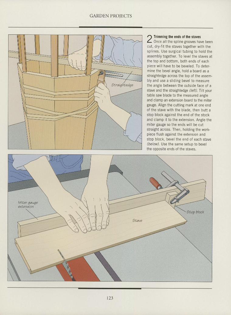
GARDEN PROIECTS
I
I
I
ttIIIItIIIIIIIIIIIIIIItIIIIII
Trimming the ends of the stavesOnce al l the spl ine grooves have been
cut, dry-f i t the staves together with thesp l ines . Use surg ica l tub ing to ho ld theassembly together. To level the staves atthe top and bottom, both ends of eachpiece wrl l have to be beveled. To deter-mine the bevel angle, hold a board as astraightedge across the top of the assem-b ly and use a s l id ing beve l to measurethe angle between the outside face of astave and the straightedge (left). Tilt yourtable saw blade to the measured angleand clamp an extension board to the mitergauge. Al ign the cutt ing mark at one endof the stave with the blade, then butt astop block against the end of the stockand c lamp i t to the ex tens ion . Ang le themi te r gauge so the ends w i l l be cu tstraight across. Then, holding the work-piece f lush against the extension andstop block, bevel the end of each stave(below). Use the same setup to bevelthe opposite ends of the staves.
t23
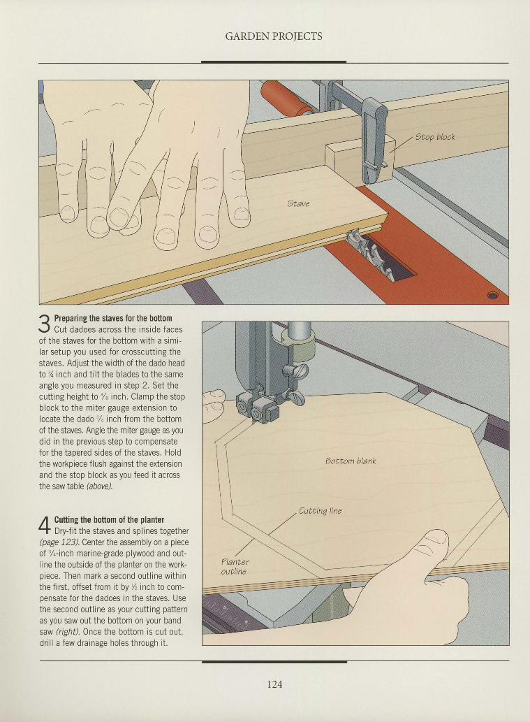
GARDEN PROIECTS
] / / H t -- 1 t t l \
ItIItIIIaIIIIIItIIIItIIttTIIIItt
Q Preparing the staves for the boftomr.J Cut dadoes across the inside facesof the staves for the bottom with a simi-lar setup you used for crosscutt ing thestaves. Adjust the width of the dado headto % inch and t i l t the blades to the sameangle you measured in step 2. Set thecutting height to 3/" inch. Clamp the stopblock to the miter gauge extension tolocate the dado 3/q inch from the bottomof the staves. Angle the miter gauge as youdid in the previous step to compensatefor the tapered sides of the staves. Holdthe workpiece flush against the extensionand the stop block as you feed it acrossthe saw Iable hbovd.
Cutting the bottom of the plantelDry-fit the staves and splines together
(page 123). Center the assembly on a pieceof %-inch marine-grade plywood and out-line the outside of the planter on the work-oiece. Then mark a second out l ine withinthe first, offset from it by % inch to com-oensate for the dadoes in the staves. Usethe second outline as your cutting patternas you saw out the bottom on your bandsaw (righil.0nce the bottom is cut out,dr i l l a few drainage holes through i t .
t24
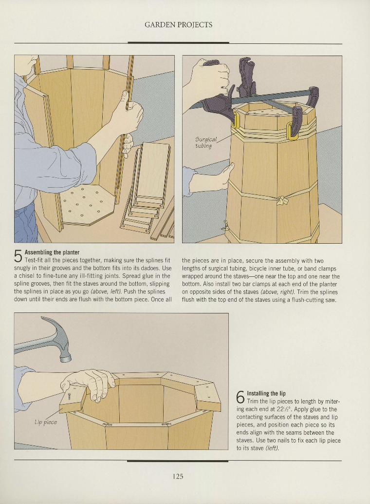
GARDEN PROIECTS
IIItIIIIIIIItIIIIIIIIIIIIIIIIIII
f, Assembling the planterr- , f Test- f i t a l l the pieces together, making sure the spl ines f i tsnugly in theirgrooves and the bottom f i ts into i ts dadoes. Usea ch ise l to f ine- tune any i l l - f i t t ing jo in ts . Spread g lue in thespl ine grooves, then f i t the staves around the bottom, sl ippingthe spl ines in place as you go (above, /ef f) . Push the spl inesdown unt i l their ends are f lush with the bottom piece. Once al l
the p ieces are in p lace , secure the assembly w i th twolengths of surgical tubing, bicycle inner tube, or band clampswrapped around the staves-one near the top and one near thebottom. Also instal l two bar clamps at each end of the planteron opposite sides of the staves (above, righil.Trim the splinesf lush with the top end of the staves using a f lush-cutt ing saw.
A Insta l l ingthe l ip\,1 Trim the l ip pieces to length by miter-ing each end aI 221/zo. Apply g lue to thecontacting surfaces of the staves and lipp ieces , and pos i t i on each p iece so i t sends a l ign wi th the seams between thestaves. Use two nai ls to f ix each l io o ieceto its stave r'leff).
t25
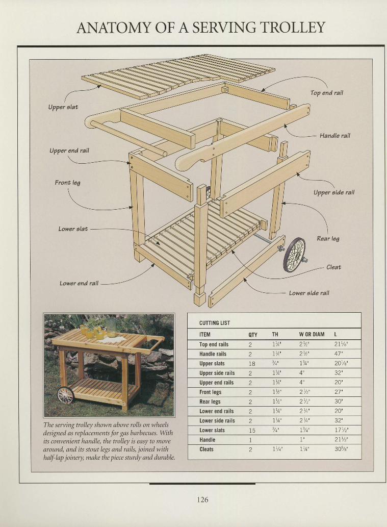
Top end rail
Upper alat
Upper end rail
Front leg
Upper aide rail
Lower end rail
Lower eide rail
The serting trolley shown above rolls on wheelsdesigned as replacements for gas barbecues. Withits convenient handle, the trolley is easy to movearound, and its stout legs and rails, joined withhalf-lap joinery, malce the piece sturdy and durable.
CUTTING IIST
ITEM OTY TH W OR DIAM t
Iop end raifs 2 LY4' 2%', 2IYe'
Handfe rails 2 I 'A' 2%' 47'
Upper slats 18 Yi' 9t' 20r/a'
Upper side rails 2 IY4' 32',
Upper end raifs 2 1Y4' 4', 20'
Front legs 2 I%" 2Yr" 27',
Rear legs 2 I '/z' 2/z' 30"
Lower end raifs 2 IY4' 2Y4 ' 20'
Lower side rails 2 IYA' 2Y4 ' 3z',lower slals 15 Yt' flt' 17 lz'
Handfe I 1' 2l ' /z '
Cleats 2 IYi' IYI' 30%'
IttttIIItIttIIItItIIIIItItIIIIII
ANATOMY OFA SERVING TROLLEY
t26
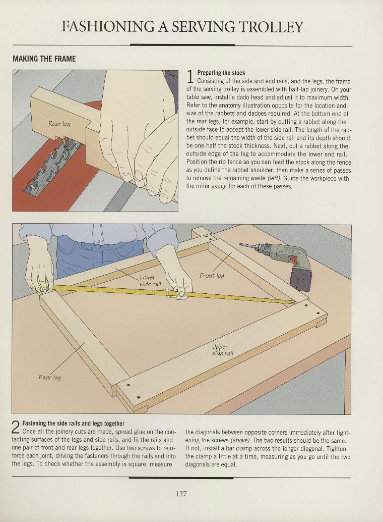
FASHIONING A SERVING TROLLEYI
I
I
tIIItIItItIIIIItIIIIttIItIIIt
MAKING THE FRAME
J Fastening the side rails and legs togetherC- Once al l the joinery cuts are made, spread glue on the con-tact ing surfaces of the legs and side rai ls, and f i t the rai ls andone pair of front and rear legs together. Use two screws to rein-force each joint , dr iv ing the fasteners through the rai ls and intothe legs. To check whether the assembly is square, measure
1 Preparing the stockI Consist ing of the side and end rai ls, and the legs, the frameof the serving trol ley is assembled with half- lap joinery. On yourtable saw, instal l a dado head and adjust i t to maximum width.Refer to the anatomy i l lustrat ion opposite for the locat ion andsize of the rabbets and dadoes required. At the bottom end ofthe rear legs, for example, start by cutt ing a rabbet along theoutside face to accept the lower side rai l . The length of the rab-bet should equal the width of the side rai l and i ts depth shouldbe one-half the stock thickness. Next, cut a rabbet along theouts ide edge o f the leg to accommodate the lower end ra i l .Posit ion the r ip fence so you can feed the stock along the fenceas you def ine the rabbet shoulder, then make a ser ies of passesto remove the remaining waste (left). Guide the workpiece withthe miter gauge for each of these passes.
the diagonals between opposite corners immediately after t ight-ening the screws (aboye). The two results should be the same.l f not, instal l a bar clamp across the longer diagonal. Tightenthe c lamp a l i t t le a t a t ime, measur ing as you go un t i l the two; ; ^ ^ ^ ^ ^ t ^ ^ - ^ ^ ^ . , ^ lu r d E U r d r J d t u c L l u d t .
t27
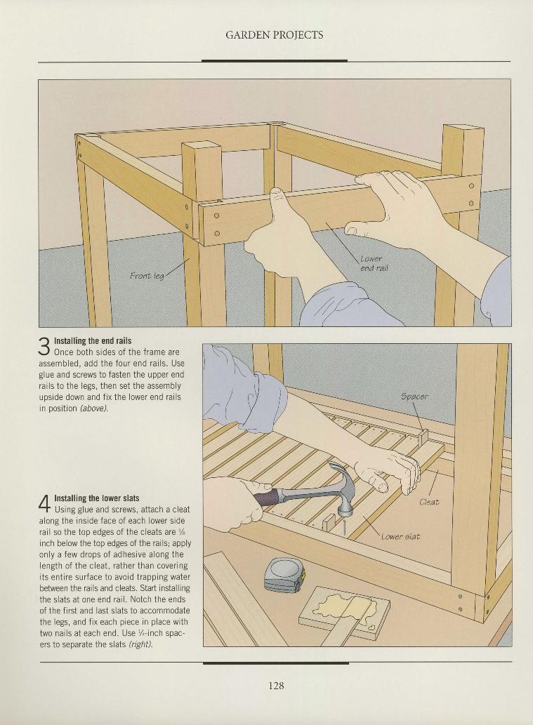
GARDEN PROIECTS
IIIttI
I
tI
tIIIIIIIIIIIIIIIIIIIIII
? Installing the end railsr- ,1 Once both sides of the frame areassembled, add the four end ra i l s . Useglue and screws to fasten the upper endrai ls to the legs, then set the assemblyupside down and f ix the lower end rai lsin position (above).
Installing the lower slatsUsing glue and screws, attach a cleat
along the ins ide face of each lower s idera i l so the top edges of the c leats are %inch below the top edges of the ra i ls ; applyon l y a f ew d rops o f adhes i ve a long thelength of the c leat , rather than cover ingi ts ent i re sur face to avoid t rapping waterbetween the rails and cleats. Start install ingthe s lats at one end ra i l . Notch the endsof the f irst and last slats to accommodatethe legs, and f ix each p iece in p lace wi thtwo nai ls at each end. Use , / , - inch spac-ers to separate the slats (rrght).
r28
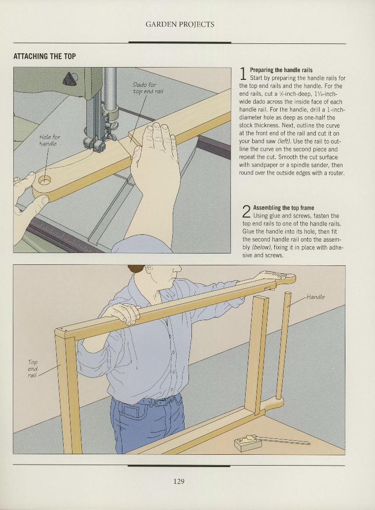
GARDE,N PROIECTS
ATTACHING THE TOP
I
I
I
ttI
I
I
I
I
tI
ttI
I
T
I
ttI
I
I
t
I
I
I
I
I
T
I
I
' l Prepar ing the handle ra i lsI Star t by prepar ing the handle ra i ls fort he top end ra i l s and the hand le . Fo r t heend ra i l s , cu t a 7 - i nch -deep , i%- inch -wide dado across the ins ide face of eachhand le ra i l . Fo r t he hand le , d r i l l a 1 - i nch -d iameter hole as deep as one-hal f thestock th ickness. Next , out l ine the curveat the f ront end of the rar l and cut i t onyour band saw (left). Use the rail to out-l ine the curve on the second p iece andrepeat the cut . Smooth the cut sur facewi th sandpaper or a spindle sander, thenround over the outside edges with a router.
r) Assembling the top frameL tJstngglue and screws, fasten thetop end ra i l s t o one o f t he hand le ra i l s .G lue the hand le i n to i t s ho le , t hen f i tthe second handle ra i l onto the assem-bly (below), f ix ing i t in p lace wi th adhe-srve and screws.
,\i \/ / \ \
/ l \ \U) )
--t:
,t
129
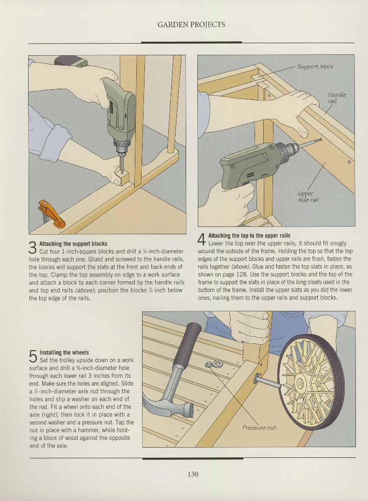
GARDEN PROTECTS
Q Attaching the support blocksr-J Cut four 1- inch-souare b locks and dr i l l a %- inch-diameterhole through each one. Glued and screwed to the handle ra i ls ,the b locks wi l l suooort the s lats at the f ront and back ends ofthe top. Clamp the top assembly on edge to a work sur faceand a t t ach a b lock t o each co rne r f o rmed by t he hand le ra i l sand top end ra i l s (above ) ; pos i t i on t he b locks % inch be lowt hp t nn pdgp n f t he ra i l s
R Insta l l ing the wheelsr . , l Set the t ro l ley upside down on a worksu r face and d r i l l a %- inch -d iame te r ho lethrough each lower ra i l 3 inches f rom i tsend. Make sure the holes are a l igned. Sl idea %- inch -d iame te r ax le rod th rough theho les and s l i p a washe r on each end o fthe rod. F i t a wheel onto each end of theaxle ?ight), then lock it in place with asecond washer and a pressure nut. Tap thenu t i n p lace w i th a hammer , wh i l e ho ld -ing a b lock of wood against the opposi teend of the ax le.
Attaching the top t0 the upper railsLower t he top ove r t he uppe r ra i l s : i t shou ld f i t snug l y
around the outs ide of the f rame. Holdrng the top so that the topedges of the support blocks and upper rails are flush, fasten therails together (above). Glue and fasten the top slats in place, asshown on page I28. Use the support blocks and the top of theframe to support the slats in place of the long cleats used in thebottom of the frame. Install the upper slats as you did the lowerones, nai l ing them to the upper ra i ls and support b locks.
I
I
I
I
I
T
I
t
T
I
I
tI
I
T
I
I
I
I
I
T
I
I
I
I
I
I
I
T
tI
I
i 30
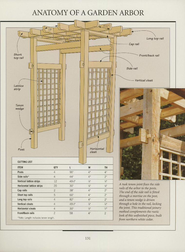
ANATOMY OF A GARDEN ARBORI
I
I
tT
I
I
I
I
I
I
I
I
tI
I
I
ttT
I
I
I
I
I
I
I
I
I
I
I
I
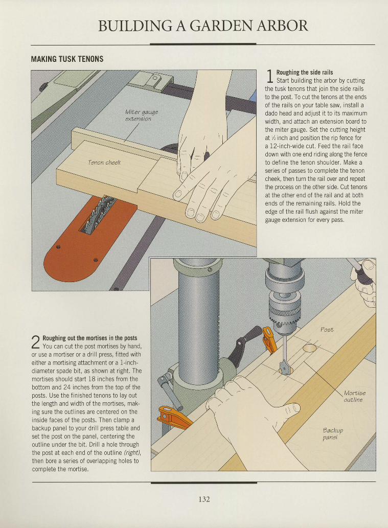
BUILDING A GARDE,N ARBOR
MAKING TUSK TENONS
r) Roughing out the mortises in the postsI you can cut the post mortises by hand,or use a mortiser or a drill press, f itted withei ther a mort is ing attachment or a f - inch-diameter spade bi t , as shown at r ight. Themort ises should start 18 inches from thebottom and 24 inches from the top of theposts. Use the f in ished tenons to lay outthe lengh and width of the mortises, mak-ing sure the out l ines are centered on theinside faces of the posts. Then clamp abackup panel to your dr i l l press table andset the post on the panel, center ing theout l ine under the bi t . Dri l l a hole throughthe post at each end of the outline (right),then bore a ser ies of overlapping holes tonnmn lo tp i hp mnr t i so
1 Roughing the side railsI Star t bui ld ing the arbor by cut t ing
the tusk tenons that jorn the s ide ra i lsto the post. To cut the tenons at the endsof the ra i ls on your table saw, insta l l adado head and adjust i t to i ts maximumwidth, and attach an extension board tothe mi ter gauge. Set the cut t ing heightat y' inch and position the rip fence fora 12- inch-wide cut . Feed the ra i l facedown with one end riding along the fenceto def ine the tenon shoulder . Make aseries of passes to complete the tenoncheek, then turn the rail over and repeatthe process on the other side. Cut tenonsat the other end of the ra i l and at bothends of the remain ing ra i ls . Hold theedge of the ra i l f lush against the mi tergauge extension for every pass.
tI
I
I
t
I
I
I
I
I
I
I
I
I
I
I
I
I
I
I
I
I
I
I
I
I
I
I
I
I
I
I
r32
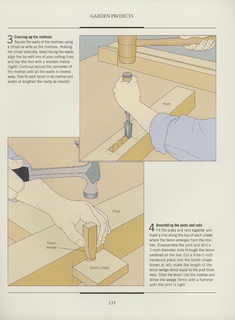
GARDEN PROIECTS
tI
I
t
I
tI
I
I
I
tI
I
I
I
I
tI
I
I
I
I
I
I
I
I
I
I
I
I
I
I
Cleaning up the mortisesSquare the walls of the mortises using
a chisel as wide as the mort ises. Hold ingthe chisel vertically, bevel facing the waste,a l ign the t ip wi th one of your cut t ing l inesand tap the tool wi th a wooden mal let(right). Conlinue around the perimeter ofthe mort ise unt i l a l l the waste is c learedaway. Tesffit each tenon in its moftise andwiden or lenghen the cavi ty as needed.
,{ Assembling the posts and rails-T Fi t the posts and rai ls together andmark a l ine along the top of each cheekwhere the tenon emerges from the mor-t i se . D isassemble the jo in t and dr i l l a1- inch-d iameter ho le th rough the tenoncentered on the l ine. Cut a %-by-1- inchhardwood p iece in to the bu l le t shapeshown at lef t ; make the length of thetenon wedge about equal to the post thick-ness. Sl ide the tenon into the mort ise ands t r i ke the wedge f i rm ly w i th a hammeru n t i l t h e j o i n t i s t i g h t .
1 3 3
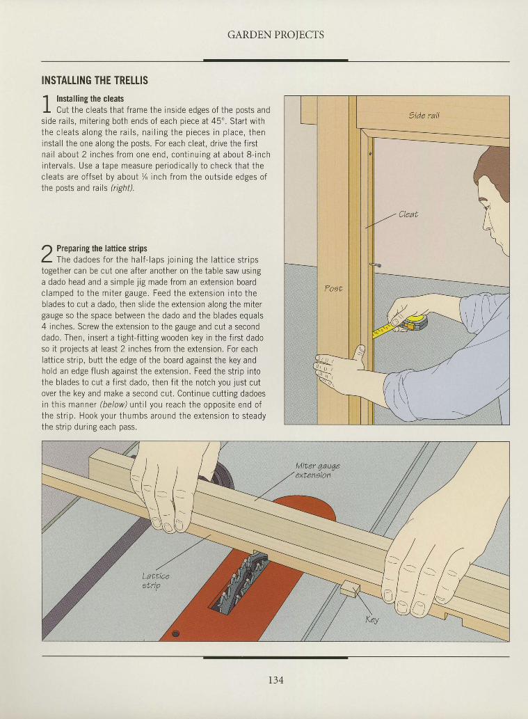
GARDEN PROIECTS
INSTALLING THE TRELTIS
1 Installing the cleatsI Cut the cleats that f rame the inside edges of the posts andside rai ls, miter ing both ends of each piece at 45' . Start withthe c lea ts a long the ra i l s , na i l ing the p ieces in p lace , theninstal l the one along the posts. For each cleat, dr ive the f i rstna i l about 2 inches f rom one end, cont inu ing a t about 8 - inchin te rva ls . Use a tape measure per iod ica l l y to check tha t thecleats are offset by about % inch from the outside edges ofthe posts and rails (right).
r') Preparing the lattice strips( - me dadoes fo r the ha l f - laps jo in ing the la t t i ce s t r ipstogether can be cut one after another on the table saw usinga dado head and a simple j ig made from an extension boardc lamped to the mi te r gauge. Feed the ex tens ion in to theblades to cut a dado, then sl ide the extension along the mitergauge so the space between the dado and the blades equals4 inches. Screw the extension to the gauge and cut a seconddado. Then, insert a t ight- f i t t ing wooden key in the f i rst dadoso it projects at least 2 inches from the extension. For eachlattice strip, butt the edge of the board against the key andhold an edge f lush against the extension. Feed the strrp intothe blades to cut a f i rst dado, then f i t the notch you just cutover the key and make a second cut. Cont inue cutt ing dadoesin this manner (below) unt i l you reach the opposite end ofthe s t r ip . Hook your thumbs around the ex tens ion to s teadythe str ip during each pass.
I
I
I
I
I
I
I
ttI
I
I
tI
I
I
I
I
I
I
tI
I
I
I
I
tI
I
I
I
I
t34
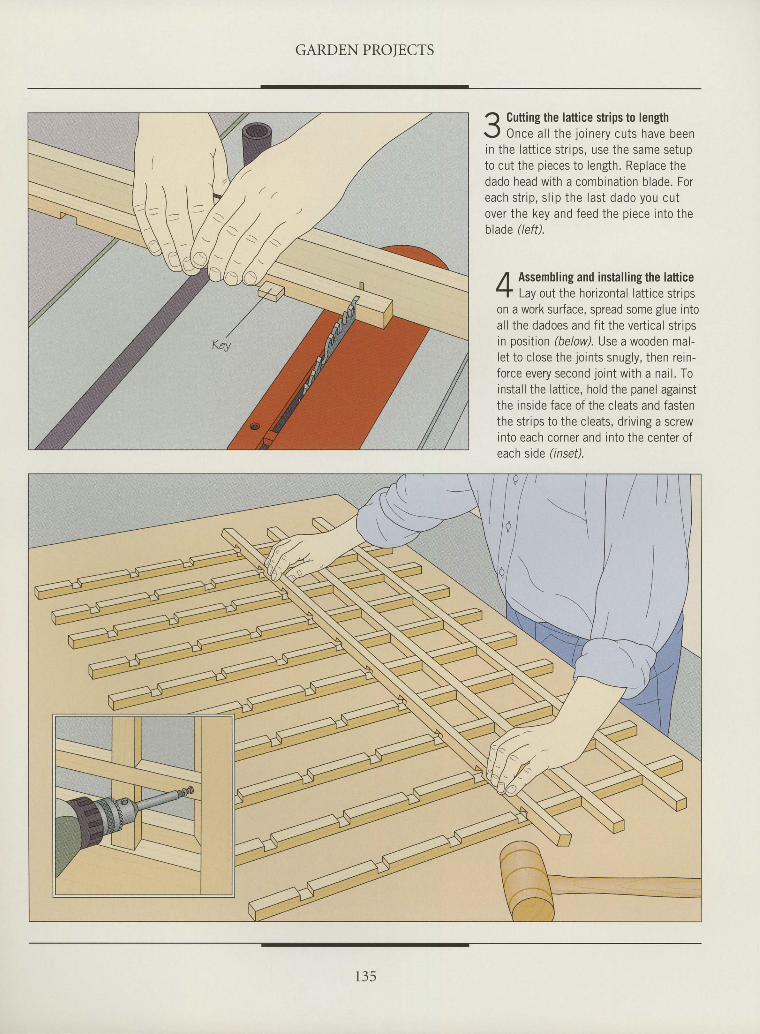
GARDEN PROIECTS
I
tI
tI
I
I
t
I
I
I
I
I
I
I
I
I
I
I
I
tI
I
I
I
I
tI
I
I
I
I
J Cutting the lattice strips to lengh<.
r - , f 0nce a l l the io inerv cuts have beenin the la t t ice st r i js , use the same setupto cut the p ieces to length. Replace thedado head wi th a combinat ion b lade. Foreach s t r i p , s l i p t he l as t dado you cu tover the key and feed the p iece in to theblade (left).
,{ Assembling and install ing the latticeT Lay out the hor izonta l la t t ice st r ipson a work surface, spread some glue intoal l the dadoes and f i t the ver t ica l s t r ipsin position (below). Use a wooden mal-le t to c lose the jo ints snugly, then re in-force every second lo int wi th a nai l . Toinsta l l the la t t ice, hold the panel againstthe ins ide face of the c leats and fastenthe st r ips to the c leats, dr iv ing a screwinto each corner and into the center ofeach side (lnsef).
t 3 5
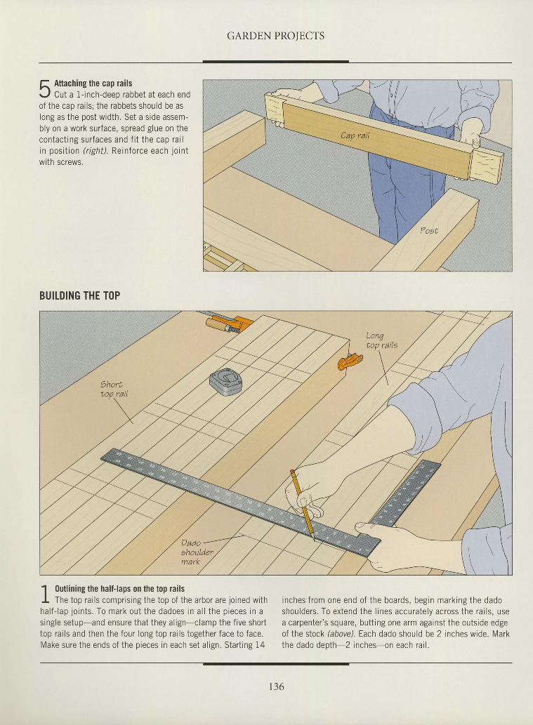
GARDEN PROTECTS
f, Attaching the cap railsr - , f Cut a 1- inch-deep rabbet at each endof the cap ra i ls ; the rabbets should be aslong as the post width. Set a srde assem-bly on a work sur face, spread g lue on thecon tac t i ng su r faces and f i t t he cap ra i lin posi t ion ( r ight) . Reinforce each jo int
with screws.
BUILDING THE T()P
' l 0utlining the half-laps on the top railsI - ,
I The top ra i ls compr is ing the top of the arbor are jo ined wi thha l f - l ap j o i n t s . To mark ou t t he dadoes i n a l l t he p ieces i n as inple setun-and ensrr re that thev a l ipn-r ' lamn the f ive shor ttop ra i ls and then the four long top ra i ls together face to face.lV lake sure the ends of the n ieces in each set a l rsn Star t ins l4
i nches f rom one end o f t he boa rds , beg in mark ing the dadoshou lde rs . To ex tend the l i nes accu ra te l y ac ross t he ra i l s , usea carpenter 's square, but t ing one arm against the outs ide edgeof the stock (above). Each dado should be 2 inches wide. Markthe dado denth 2 inches-on each ra i l .
tI
I
I
I
tI
I
tI
I
I
I
I
I
I
I
I
I
I
I
I
I
I
I
I
I
I
I
I
I
I
r36
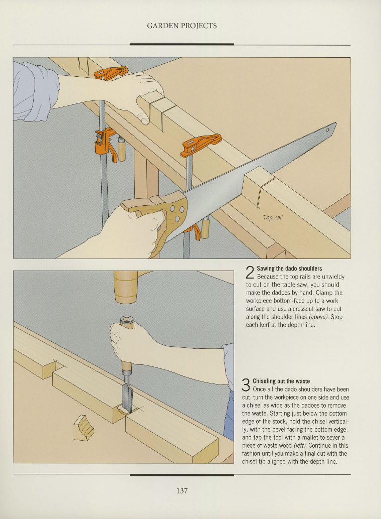
GARDEN PROTECTS
I
I
I
ttI
nI
I
I
tII
I
I
I
I
tI
I
I
I
I
I
I
I
T
tI
I
I
I
r) Sawing the dado shouldersZ- Because the top rai ls are unwieldyto cu t on the tab le saw, you shou ldmake the dadoes by hand. C lamp theworkpiece bottom-face up to a worksurface and use a crosscut saw to cutalong the shoulder l ines (above). Stopeach kerf at the depth l ine.
Q Chiseling out the waster., l Once all the dado shoulders have beencut, turn the workpiece on one side and usea chisel as wide as the dadoes to removethe waste. Starting just below the bottomedge of the stock, hold the chisel ver t ica l -ly , wi th the bevel fac ing the bot tom edge,and tao the tool wi th a mal let to sever apiece of waste wood (/eff). Continue in thisfashion unt i l you make a f ina l cut wi th thech rse l t r p a l i gned w i th t he dep th l i ne .
137
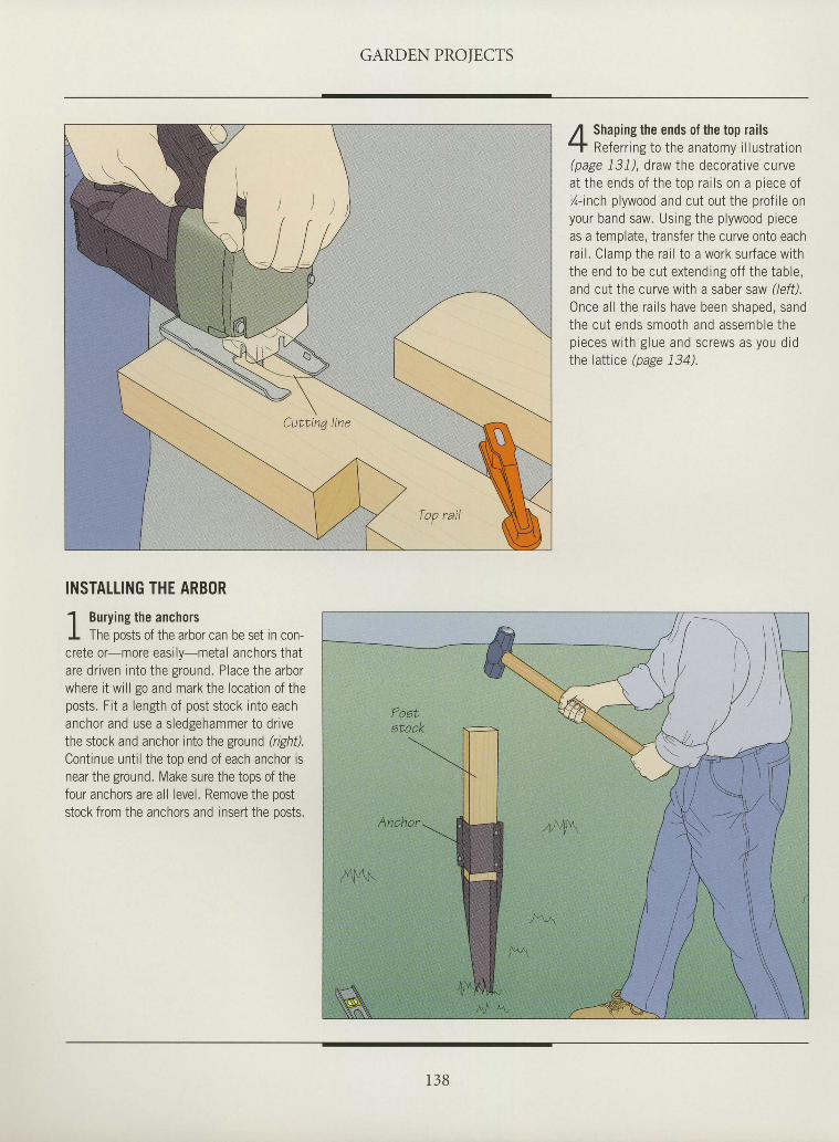
GARDEN PROIECTS
/l Shaping the ends of the top railst a' t Re fe r r i ng t o t he ana tomy i l l us t ra t i on(nase 1 .3 / ) draw the decorat ive curvea l l h p p n d q n f i h p i n n r : i l c n n : n i p e p n f
Z- inch p lywood and cut out the prof i le onyour band saw. Using the p lywood p ieceas a template, t ransfer the curve onto eachra i l . C lamp the ra i l t o a wo rk su r face w i ththe end to be cut extending of f the table.and cut the curve with a saber saw (lefi l .
Once a l l t he ra i l s have been shaped , sandthe cu t ends smoo th and assemb le t hen r p n p c u r r t h o l r r o : n d ' ^ r i lp , u ! u J v v , L r ' B r u u u i l u J U I U v V ) d ) y U U U I U
i h p l : t i i n p / n e o p I ? 4 )\ F e b e 4 e ' / '
ttI
I
I
I
l,
I
I
I
I
I
tI
I
I
III
I
I
I
I
I
I
I
I
I
I
I
I
I
INSTALLING THE ARBOR
1 Burvins the anchorsl -
I The posts of the arbor can be set in con-crete or-more easi ly-metal anchors thatare dr iven in to the ground. Place the arborwhere i t wi l l go and mark the locat ion of thenosts. F i t a length of nost s tock in to eachanchor and use a s ledgehammer to dr ivethe stock and anchor into the ground (righil.
Contrnue unt i l the top end of each anchor isnear the ground. Make sure the tops of thefour anchors are all level. Remove the poststock from the anchors and insert the nnsts
1 3 8
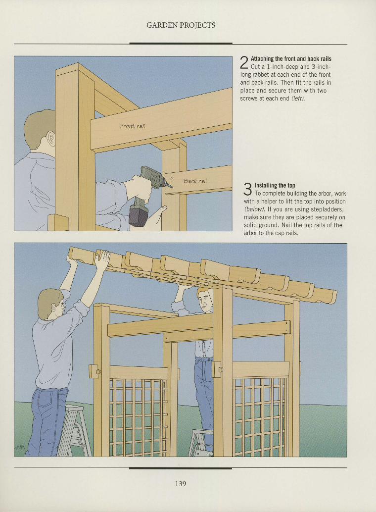
GARDEN PROTECTS
I
I
I
t
tI
I
I
I
I
tI
I
I
l
I
I
I
I
I
I
I
I
I
t
I
I
I
I
I
I
I
r) Attaching the front and back railsI Cu t a 1 - i nch -deep and 3 - i nch -long rabbet at each end of the f ronta n d b a c k r a i l s . T h e n f i t t h e r a i l s i nn l a c e a n d s e c r r r e t h e m w i t h t w oscrews at each end (left)
-) Instal l ins the ton<'
r - .1 To complete bui ld ing the arbor , workwi th a helper to l r f t the top in to posi t ion(be low) . l f you a re us ing s tep ladde rs .make su re t hey a re p laced secu re l y ons o l i d g r o u n d . N a i l t h e t o p r a i l s o f t h earbor to the cap ra i ls .
139
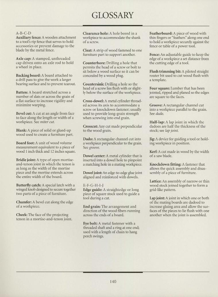
GLOSSARY
A-B-C-DAuxiliary fence A wooden attachmentto a tool's rip fence that serves to holdaccessories or prevent damage to theblade by the metal fence.
Axle cap: A stamped, unthreadedcap driven onto an axle rod to holda wheel in place.
Backingboard: A board attached toa drill pass to give the work alargerbearing surface and to prevent tearout.
Batten: A board stretched across anumber of slats or across the grain ofa flat surface to increase rigidity andminimize warping.
Bevel cut A cut at an angle from faceto face along the length or width of aworkpiece. See miter cut.
Blank A piece of solid or glued-upwood used to create a furniture part.
Board foot A unit of wood volumemeasurement equivalent to a piece ofwood I inch thick and 12 inches square.
Bridle joint A tfpe of open mortise-and-tenon joint in which the tenon isas long as the width of the mortisepiece and the mortise extends acrossthe entire width of the board.
Butterflycatch: A special latch with awingedknob designed to secure togethertwo parts of a piece of furniture.
Chamfer: A bevel cut along the edgeof a workpiece.
Cheek The face of the projectingtenon in a mortise-and-tenon joint.
Clearance hole: A hole bored in aworkpiece to accommodate the shankof a screw.
Cleafi A strip of wood fastened to onefurniture part to support another.
Counterbore: Drilling a hole thatpermits the head of a screw or bolt tosit below a wood surface so it can beconcealed by a wood plug.
Countersink: Drilling a hole so thehead of a screw lies flush with or slight-ly below the surface of the workpiece.
Cross-dowek A metal cylinder thread-ed across its axis to accommodate ascrew or knockdown fastener; usuallyused to provide long-grain strengthwhen screwing into end grain.
Crosscut Any cut made perpendicularto the wood grain.
Dado: A rectangular channel cut intoa workpiece perpendicular to the grain.See groove.
Dowel center: A metal cylinder that isinserted into a dowel hole to pinpointa matching hole in a mating workpiece.
Dowel joint An edge-to-edge glue jointaligned and reinforced with dowels.
E-F-G-H-r-lEdge guide A straightedge or longpiece of square stock used to guide atool during a cut.
End grain: The arrangement anddirection of the wood fibers runningacross the ends of a board.
Eye bolt: A metal fastener with athreaded shaft and a ring at one end;used with a length of chain to hangporch swings.
Featherboard: A piece of wood withthin fingers or "feathers" along one endto hold a workpiece securely against thefence or table of a power tool.
Fence: An adjustable guide to keep theedge of a workpiece a set distance fromthe cutting edge of a tool.
Flush trimmingbit A piloted straightrouter bit used to cut wood flush witha template.
Four square: Lumber that has beenjointed, ripped and planed so the edgesare square to the faces.
Groove: A rectangular channel cutinto a workpiece parallel to the grain.See dado.
Half-lap: A lap joint in which thedadoes are half the thickness of thestock; see lap joint.
|ig: A device for guiding a tool or hold-ing workpiece in position.
Kerf, A cut made in wood by the widthofa saw blade.
Knockdown fitting: A fastener thatallows the quick assembly and disas-sembly of a piece of furniture.
Lattics An assembly of narrow or thinwood stock joined together to form agridJike pattern.
Iap joint A joint in which one or bothof the mating boards are dadoed toincrease gluing area and allow the sur-faces of the pieces to lie flush with oneanother when the joint is assembled.
IIIIIIItIIIIIIIIIIIIIIIIIIIIIIII
140
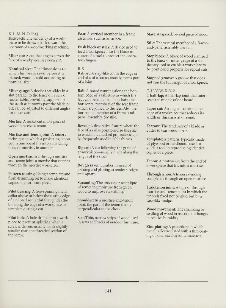
III7IIIIIIIIIIIII3IIItIIIItIIIII
K-L-M-N-O-P-QKickback The tendenry of a work-piece to be thrown back toward theoperator of a woodworking machine.
Miter cut A cut that angles across theface of a workpiece; see bevel cut.
Nominal size: The dimensions towhich lumber is sawn before it isplaned; wood is sold according tonominal size.
Miter gauge A device that slides in aslot parallel to the fence on a saw orrouter table, providing support forthe stock as it moves past the blade orbit; can be adjusted to different anglesfor miter cuts.
Mortiss A socket cut into a piece ofwood to receive a tenon.
Mortise-and-tenon joint A joinerytechnique in which a projecting tenoncut in one board fits into a matchinghole, or mortise, in another.
Open mortise: In a through mortise-and-tenon joint, a mortise that extendsthrough the mortise workpiece.
Pattern routing: Using a template andflush-trimming bit to make identicalcopies of a furniture piece.
Pilot bearing: A free-spinning metalcollar above or below the cutting edgeof a piloted router bit that guides thebit along the edge of a workpiece ortemplate during a cut.
Pilothole: A hole drilled into a work-piece to prevent splitting when ascrew is driven; usually made slightlysmaller than the threaded section ofthe screw
Post: A vertical member in a frameassembly, such as an arbor.
Push block or stick A device used tofeed a workpiece into the blade orcutter of a tbol to protect the opera-tor's fingers.
R.SRabbet A stepJike cut in the edge orend of a of a board; usually forms partof a joint.
Raift A board running along the bot-tom edge of a tabletop to which thelegs can be attached; in a chair, thehorizontal members of the seat framewhich are joined to the legs. Also thehorizontal member of a frame-and-panel assembly. See stile.
Reveah A decorative feature where theface of a rail is positioned so the stileto which it is attached protrudes slight-ly; frequently used in table frames.
Rip cut A cut following the grain ofa workpiece-usually made along thelength ofthe stock.
Rough sawn: Lumber in need ofjointing and planing to render straightand square.
Seasoning: The process or techniqueof removing moisture from greenwood to improve its stability.
Shoulder: In a mortise-and-tenonjoint, the part of the tenon that isperpendicular to the cheek.
Slafi Thin, narrow strips of wood usedin seats and back of outdoor furniture.
Stave A tapered, beveled piece ofwood.
Stile: The vertical member of a frame-and-panel assembly. See rarl.
Stop block A block of wood clampedto the fence or miter gauge of a sta-tionary tool to enable a workpiece tobe positioned properly for repeat cuts.
Stopped groove: A groove that doesnot run the firll length of a workpiece.
T.U-V-W-X.Y-ZT halfJap: A halfJap joint that inter-sects the middle of one board.
Thper cut An angled cut along theedge of a workpiece that reduces itswidth or thickness at one end.
Tearout The tendenry of a blade orcutter to tear wood fibers.
Template: A pattern, typically madeofplywood or hardboard, used toguide a tool in reproducing identicalcopies of a piece.
Tenon: A protrusion from the end ofa workpiece that fits into a mortise.
Through tenon: A tenon extendingcompletely through an open mortise.
Tusk tenon joint A type of throughmortise-and-tenon joint in which thetenon is fixed not by glue, but by atusklike wedge.
Wood movement The shrinking orswelling of wood in reaction to changesin relative humidity.
Zincplating: A procedure in whichmetal is electroplated with a thin coat-ing of zinc; used in some fasteners.
r4l
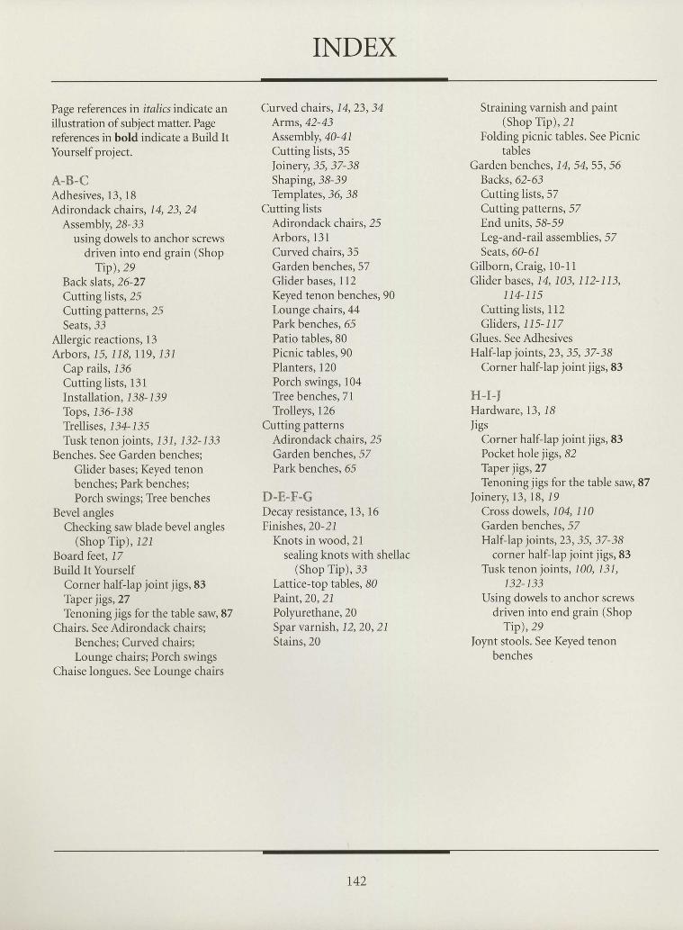
INDEX
Page referencesin italics indicate anillustration of subject matter. Pagereferences in bold indicate a Build ItYourself project.
A-B.CAdhesives, 13, 18Adirondack chairs, 14,23, 24
Assembly,28-33using dowels to anchor screws
driven into end grain (ShopTip),29
Backslats,26-27Cutting lists,25Cutting patterns, 25Seats, 33
Allergic reactions, 13Arbors, 15, 118, lI9, 131
Cap rails, 136Cutting lists, 131Installation, 1 38- 1 i9Tops,136-1j8Trellises, 1 34- 1 i5Tirsk tenon joints, 1 31, 132- 133
Benches. See Garden benches;Glider bases; Keyed tenonbenches; Park benches;Porch swings; Tiee benches
Bevel anglesChecking saw blade bevel angles
(Shop Tip), 121Board feet, 17Build It Yourself
Corner half-lap joint jigs, 83Taper jigs,27Tenoning jigs for the table saw, 87
Chairs. See Adirondack chairs;Benches; Curved chairs;Lounge chairs; Porch swings
Chaise longues. See Lounge chairs
Curved chairs, 14,23, 34Arms,42-43Assembly,40-41Cutting lists, 35foinery, 35,37-38Shaping,38-39Templates,36,38
Cutting listsAdirondack chairs,25Arbors, 131Curved chairs,35Garden benches, 57Glider bases, 112Keyed tenon benches, 90Lounge chairs,44Park benches, 65Patio tables, 80Picnic tables, 90Planters, 120Porch swings, 104Tree benches, 71Trolleys, 126
Cutting patternsAdirondack chafus,25Garden benches, 57Park benches, 65
D-E-F-GDecay resistance, 13, 16Finishes,20-21
Knots in wood,21sealing knots with shellac
(Shop Tip), 33Lattice-top tables, 80Paint,20,21Polyurethane,20Spar varnish, 12,20, 21Stains,20
Straining varnish and paint(Shop Tip),21
Folding picnic tables. See Picnictables
Garden benches, 14, 54,55,56Backs,62-63Cutting lists, 57Cutting patterns, 52End units, 58-59Leg-and-rail assemblies, 52Seats. 60-61
Gilborn, Craig, l0-11Glider bases, 14 103, 1 12- 113,
114-115Cutting lists, 112Gliders. 115-117
Glues. See AdhesivesHalf-lap joints, 23, 35, 37-38
Corner half-lap joint jigs, 83
H-I-IHardware, 13, 18JigS
Corner half-lap joint jigs,83Pocket hole jigs, 82Taper jigs,27Tenoning jigs for the table saw, 87
foinery, 13,18,19Cross dowels, 104, 110Garden benches, 57Half-lap joints, 23,35, 37-38
corner half-lap joint jigs, 83Tusk tenon joints, 100, 131,
132-133Using dowels to anchor screws
driven into end grain (ShopTip),29
Joynt stools. See Keyed tenonbenches
IttIIIIIIIIIIII.l
ItIIIIIIIIItIIII
r42
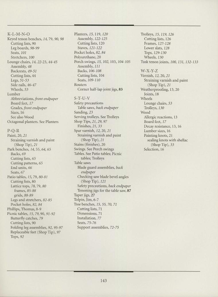
IIIaIIIIIItIIIIIIIIIIItIIIIIItIt
K-t-M-N-OKeyed tenon benches, 14,79, 90, 98
Cutting lists, 90Legboards,9S-99Seats, l0lStretchers, 100
Lounge chairs, 14, 22-23,44-45Assembly,48Backrests, 49-51Cutting lists,44Legs,5I-53Side rails,46-47Wheels.53
LumberAbbreviation s, front endp ap erBoard feet, 17Grades, front endpaperSizes, 16See also Wood
Octagonal planters. See Planters
P-Q-RPaint,20,21
Straining varnish and paint(Shop Tip),2I
Park benches, 14,55,64, 65Backs,69Cutting lists, 65Cutting patterns, 65End units. 66Seats, 67
Patio tables, 1 5, 79, 80-81Cutting lists, 80Lattice tops,78,79,80
frames,85-88grids,88-89
Legs and stretchers, 82-85Pocket holes,82, 84
Phillips, Thomas,8-9Picnic tables, 15, 79,90, 91-92
Butterfly catches, T9Cutting lists, 90Folding leg assemblies,92, 95-97Replaceable feet (Shop Tip),97Tops,92
Planters, 15, II9, 120Assembly, 122-125Cutting lists, 120Staves, l2l-122
Pocket holes,82, 84Polyurethane,20Porch swings, 15, 702,103, 104-105
Assembly, llIBacks.106-108Cutting lists, 104Seats, 109-110
RoutersCorner half-lap joint jigs,83
S-T-U-VSafety precautions
Thble saws, back endpaperSanding,23Serving trolleys. See TiolleysShop Tips, 21, 29,97
Finishes,2l, 33Spar varnish, 12,20, 21
Straining varnish and paint(Shop Tip),21
Stains (finishes),20Swings. See Porch swingsThbles. See Patio tables; Picnic
tables; TiolleysThble saws
Blade guard assemblies, backendpaper
Checking saw blade bevel angles(Shop Tip), .l2l
Safety precautions, back endpaperTenoning jigs for the table saw, 87
Taper jigs,27Tolpin, Jim,6-7Tree benches, 15, 55, 70, 71
Cutting lists, 7lDimensions, TlInstallation, ZZSeats,75-76Support assemblies, 72-25
Trolleys, 15,119,126Cutting lists, 126Frames, 127-128Lower slats, I28Tops, 129-130Wheels,l30
Tlrsktenon joints, 100, ]31, 132-133
W.X-Y-ZVarnish, 12,20, 21
Straining varnish and paint(Shop Tip),2l
Weatherproofing, 13,20foints, 18
WheelsLounge chairs, 53Trolleys, 130
WoodAllergic reactions, 13Boardfeet, 17Decay resistance, 13, 16Lumber sizes, 16Painting knots,2l
sealing knots with shellac(Shop Tip), 33
Selection, l6
143

ACKNOWTEDGMENTSThe editors wish to thank the following
CHAIRSAdjustable Clamp Co., Chicago, IL; Black & DeckeriElu Power Tools, Towson, MD;
CMT Tools, Oldsmar, FL; Delta International Machinery/Porter-Cable, Guelph, Ont.;Ryobi America Corp., Anderson, SC; Sears, Roebuck and Co., Chicago, IL;
Stanley Tools, Division of the Stailey Works, New Britain, CT; The Woodworker's Store, Rogers, MN;Tool Trend Ltd., Concord, Ont.; Wainbee Ltd., Pointe Claire, Que./DE-STA-CO, Troy, MI
BENCHESAdjustable Clamp Co., Chicago, IL; CMT Tools, Oldsmar, FL;
Delta International Machinery/Porter-Cable, Guelph, Ont.; Dynbort & Martineault, Montreal, Que.;Milwaukee Electric Tool Corp., Brookfield, WI; Sandvik Saws and Tools Co., Scranton, PA;
Sears, Roebuck and Co., Chicago, IL; Stanley Tools, Division of the Stanley Works, New Britain, CT
TABLESAdjustable Clamp Co., Chicago, IL; Delta International Machinery/Porter-Cable, Guelph, Ont.;Black & Decker/Elu Power Tools, Towson, MD; Freud Westmore Tools, Ltd., Mississauga, Ont.;
Great Neck Saw Mfrs. Inc. (Buck Bros. Division), Millbury, MA;Milwaukee Electric Tool Corp., Brookfield, WI; Sears, Roebuck and Co., Chicago, IL;
M.E. Wyant Distributing Inc., Nottawa, Ont.
SWINGS&GLIDERSAdjustable Clamp Co., Chicago, IL; American Tool Cos., Lincoln, NE; CMT Tools, Oldsmar, FL;Delta International Machinery/Porter-Cable, Guelph, Ont.; Sears, Roebuck and Co., Chicago, IL;Stanley Tools, Division of the Stanley Works, New Britain, CT; Tool Trend Ltd., Concord, Ont.
GARDENPROIECTSAdjustable Clamp Co., Chicago, IL; American Tool Cos., Lincoln, NE;
Delta International Machinery/Porter-Cable, Guelph, Ont.; Sears, Roebuck and Co., Chicago, IL.;Stanley Tools, Division of the Stanley Works, New Britain, CT;
IIIIIIIIIIIIIIIIIIIIIIIIIIIIIIII
The following persons also assisted in the preparation of this book:
Normand Boudreault, Ingrid Chartrand, Lorraine Dor6, Isabel Gales
PICTURE CREDITS
Cover Robert Chartier6,7 Raymond Gendreau
8,9 Ed Homonylo/Mammothl0,ll Ed Homonylo/Mammoth
r44
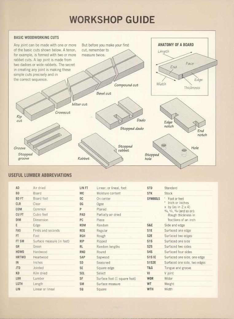
IIIIIIItIIIIItIIIItItIIIIIIIItII
WORKSHOP GUIDE
USEFUT TUMBER ABBREVIATIONS
AD A i r d r ied
BD Board
BD FT Board foot
CLR Clear
C()M Common
CU FT Cub ic fee t
DIM Dimens ion
E Edge
FAS Firsts and seconds
FT Foot
FT SM Surface measure ( in feet)
GR Green
HDWD Hardwood
HRTWD Heartwood
lN Inches
JTD Jo in ted
K D K i l n d r i e d
LBR Lumber
LGTH Length
L IN L inear o r l inea l
L inear , o r l inea l , foo t
Mois tu re conten t
0n center
Ogee
Planed
Par t ia l l y a i r d r ied
Piece
Random
Regu la r
Rough
R i pped
Random lengths
Rou nd
Sapwood
Seasoned
Square edge
Se lect
Surface foot (1 square foot)
Surface measure
Sq u are
Standard
Stock' Foot or feet' l n c h o r i n c h e sx b y ( a s t n 2 x 4 )alq, 6lq, Blq (and so on):
Rough th ickness inf rac t ions o f an inch
Side and edgeSr r r faeod nno odoo
Surfaced two edges
Sur faced one s ide
Surfaced two sides
Surfaced four sides
Sur faced one s ide , one edge
Surfaced one side, two edges
T n n o r r e a n d q r n n r r p
V jo int
Wider
Weightwidth
TIN FT
MC
0cOG
P
PAD
PC
RDM
REG
RGH
RIP
RL
RND
SAP
S D
SE
SEt
SF
SM
s0
STDSTK
SYMBOTS
s&Es l Es2Es l ss2ss4ss l s 1 Esls2ET&GVJWDRWT
WTH
BASIC W()ODW()RKING CUTS
Any jornt can be made wi th one or moreof the basic cuts shown below. A tenon,for examole. is formed with two or morerabbet cuts. A lap lo int is made f romtwo dadoes or wide rabbets. The secretin creat ing any lo int is making theses imp le cu t s p rec i se l y and i nt h p n n r r p n t q p n r p n a o
But before you make your f irstcut, remember tomeasure twice.
Compound aut
Croescut
Miter cut
Kabbet
Stoppedrabbet
Hole
9toppedhole
notch
ANATOMY OF A BOARD