the art of ergonomics - · pdf fileergonomics is a relatively new science combining know- ......
TRANSCRIPT

The Art of Ergonomics

Contents1. What is ergonomics? ............................................................................. 4
2. Why ergonomics? .................................................................................. 4
3. Handle design ......................................................................................... 5 3.1 Bow handle ........................................................................................ 6 3.2 Pistolgrip handles .............................................................................. 7 3.3 Straight handles ................................................................................. 8 3.3.1 Screwdrivers and drills ........................................................... 8 3.3.2 Grinders and angle nutrunners ................................................ 9
4. Triggers ................................................................................................. 10 4.1 Finger triggers ................................................................................. 10 4.2Twofingertriggers ........................................................................... 10 4.3 Thumb triggers ................................................................................ 11 4.4 Lever triggers ................................................................................... 11 4.5 Push start ......................................................................................... 11 4.6 Strip trigger ...................................................................................... 11
5. Torque reaction in fastening tools ...................................................... 12 5.1 Impact wrenches .............................................................................. 12 5.2 Impulse tools ................................................................................... 12 5.3 Direct driven tools 5.3.1 Pneumatic shut-off tools ....................................................... 13 5.3.2 Electric nutrunners ................................................................ 13 5.4 Reaction bars ................................................................................... 14 5.5 Balancers ......................................................................................... 15
6. Sound .................................................................................................... 16 6.1 What is sound? ................................................................................. 16 6.2 How does sound affect us? .............................................................. 16 6.3 Measurement to establish noise emission values ............................ 17 6.4 Health and safety regulations .......................................................... 17 6.5 The Physical Agents (Noise) Directive ........................................... 17
7. Sources of noise in pneumatic tools .................................................... 19 7.1 Process noise ................................................................................... 19 7.2Airflownoise .................................................................................. 19 7.3 Vibration induced noise ................................................................... 19
8. Methods of reducing noise .................................................................. 20 8.1 Process noise ................................................................................... 20 8.2Airflownoise .................................................................................. 21 8.3 Vibration induced noise ................................................................... 22 8.4 Noise control at the workplace ........................................................ 22

9. Vibration in handheld tools ................................................................ 23 9.1 What is vibration? ............................................................................ 23 9.2 Why is vibration a concern? ............................................................ 23 9.3 Measurement to establish vibration emission values ...................... 24 9.4 Health and safety regulations .......................................................... 24 9.5 The Physical Agents (Vibration) Directive ...................................... 25
10. Source of vibration .............................................................................. 26
11. Reducing vibration in handheld tools ................................................ 27 11.1 Grinders ......................................................................................... 27 11.2 Die grinders ................................................................................... 27 11.3 Angle and vertical grinders ............................................................ 27 11.4 Turbo grinders ................................................................................ 27 11.5 Percussive tools ............................................................................. 28 11.6 Chipping hammers ......................................................................... 29 11.7 Riveting hammers .......................................................................... 29 11.8 Bucking bars .................................................................................. 29 11.9 Scalers ............................................................................................ 29 11.10 Impact wrenches and impulse tools ............................................. 30
12. Lubrication-free motors ...................................................................... 31
13. Dust control .......................................................................................... 32 13.1 Why control dust? .......................................................................... 32 13.2 Health ............................................................................................ 32 13.3 How to control dust ....................................................................... 32
14. Extraction systems for tools ................................................................ 33 14.1 Disc sanders ................................................................................... 33 14.2 Orbital and random orbital sanders ............................................... 33 14.3 Depressed center grinders .............................................................. 33 14.4 Straight grinders ............................................................................ 33 14.5 Die grinders ................................................................................... 33 14.6 Diamond tipped grinders ............................................................... 33 14.7 Drills .............................................................................................. 33 14.8 Chipping hammers ......................................................................... 34
15. Vacuum sources ................................................................................... 35 15.1 Installation of extraction systems .................................................. 36

4 T H E A R T O F E R G O N O M I C S
1. What is ergonomics?
Ergonomics is a relatively new science combining know-ledge mainly from three disciplines: human science, work-related sciences and production science.
Ergonomics describes a complex interaction between the operator and his working environment. Power tools with good ergonomic design are an essential element with regard to achieving a good ergonomic workplace. At the same time they are only one of the several contributing factors involved.
2. Why ergonomics?
In today´s competitive market, the drive to achieve high pro-ductivity with high quality production is strong. Many com-panies now realize the important contribution that ergonomic workstations can make towards achieving this goal.
More and more companies have come to realize that work related disorders cost a lot of money. Not only for the re-habilitation of injured persons but also for lost productivity and for quality problems related to workplaces with poor ergonomics. Studies have been published that indicate that those costs are often several times greater than the direct cost for rehabilitation. With this taken into account good ergo-nomic design of workplaces and tools can save companies a great deal of money.
Workstations and working practices should be designed to avoid exposing the operator to unnecessary physical load, noise, vibration and dust.
Hand tools are of particular importance because they form the direct link between operator and process.
The aim of this pocket guide is to give the reader an under-standing of how handheld tools can be designed to avoid unnecessary strain on the operator.

5T H E A R T O F E R G O N O M I C S
3. Handle design
The handle is the interface between the operator and the tool. All forces associated with the task are transmitted between the hand and handle. An ergonomic handle design is vital in producing a tool that places the minimum strain on the operator.
To ensure the optimum position for transmitting forces bet-ween hand and arm, the wrist must be kept straight. It is also important to reduce, as far as possible, the twisting and ben-ding forces applied to the wrist. As there are many different working positions most tools are available with a selection of handle types.
All tools should be designed to have a high power-to-weight ratio. Heavy tools not only put a higher load on the wrist, theyalsomakeprecisiontasksmoredifficult.
This section looks at the design of the different handles and explains the applications they should be used for.
There are many different handle designs. It is important to choose the best design for every application.

6 T H E A R T O F E R G O N O M I C S
3.1 Bow handle
This type of handle is used to transmit high feed forces with-out causing a torque in the wrist. To achieve this, the handle should be designed to ensure the feed force is transmitted through the center line of arm and wrist.
The natural angle of the handgrip is independent of hand size. This angle is approximately 70 degrees.
By making the handle at this angle the muscles stabilizing the wrist are in the optimal position.
The limitation of this design is that the weight of the tool is put in front of the hand. If used as a single handed tool it would put a high bending force on the wrist, which is unde sirable.
This handle is ideal for chipping hammers and big riveting hammers.
The bow handle is ideal for tools requiring high feed forces.
7T H E A R T O F E R G O N O M I C S
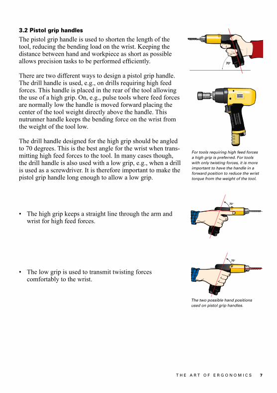
3.2 Pistol grip handles
The pistol grip handle is used to shorten the length of the tool, reducing the bending load on the wrist. Keeping the distance between hand and workpiece as short as possible allowsprecisiontaskstobeperformedefficiently.
There are two different ways to design a pistol grip handle. The drill handle is used, e.g., on drills requiring high feed forces. This handle is placed in the rear of the tool allowing the use of a high grip. On, e.g., pulse tools where feed forces are normally low the handle is moved forward placing the center of the tool weight directly above the handle. This nutrunner handle keeps the bending force on the wrist from the weight of the tool low.
The drill handle designed for the high grip should be angled to 70 degrees. This is the best angle for the wrist when trans-mitting high feed forces to the tool. In many cases though, the drill handle is also used with a low grip, e.g., when a drill is used as a screwdriver. It is therefore important to make the pistol grip handle long enough to allow a low grip.
• Thehighgripkeepsastraightlinethroughthearmand wrist for high feed forces.
• Thelowgripisusedtotransmittwistingforces comfortably to the wrist.
For tools requiring high feed forces a high grip is preferred. For tools with only twisting forces, it is more important to have the handle in a forward position to reduce the wrist torque from the weight of the tool.
The two possible hand positions used on pistol grip handles.

8 T H E A R T O F E R G O N O M I C S
3.3 Straight handles
Handle diameters of 38 mm for men and 34 mm for women have been found to allow the strongest grip and cause the minimum strain in the hand when held. Consideration to the probable gender of the worker should be given when designing a tool.
The next aspect to consider is whether the tool produces a twisting torque in the hand (screwdrivers and drills) or pro-duces a levering torque on the wrist and arm (grinders and angle nutrunners).
3.3.1 Screwdrivers and drills
For tools used in light assembly work a diameter of 34 mm should be aimed for. This is because many operators in this environment are female. As the male grip tends to be stronger, men are less affected by a small deviation from their optimum diameter.
For applications, such as drilling, where male operators dominate, a 38 mm handle diameter should be used.
High torque can comfortably be handled with lower grip force if the handle has an ergonomic design. The surface should have a visco-elastic coating with high friction. The texture should allow ventilation of the grip. A tapered handle allowsallfingerstogripequally.
For ease of movement and to minimize loading of the wrist the tool should be kept short with the center of balance where the tool is gripped. Keeping the distance between hand and workpiece as short as possible speeds up precision tasks.
Straight handles can be used either for twisting torque or for levering torque applications.
For screwdrivers used mainly by female operators the best handle diameter is 34 mm.
For drilling, a handle diameter of 38 mm should be used.

9T H E A R T O F E R G O N O M I C S
3.3.2 Grinders and angle nutrunners
In the case of angle nutrunners, particularly on tools with a high torque capacity, it is important to ensure a secure grip on the tool. As these tools are mainly used by men a handle diameter of 38 mm is most suitable.
With die grinders the forces on the hand and wrist are often lower than with other tools but they are used over longer time periods. The comfort level for operators can be im-proved by making the handle from an insulating material, protecting the hand from the cold temperature of the expand-ing exhaust air.
On rough grinders requiring two handed operation and high-er feed forces it is important to have an ergonomic handle design. The support handle should be adjustable. The main handle should preferably be angled allowing a more natural wrist angle. The distance from the support handle to the grinding spot should be kept short to reduce wrist torque.
Today the grip surface on most handles is covered with a visco-elastic material. The grip is appreciated as more com-fortable, friction is improved and the handle feels less cold.
Put the support handle in the most suitable position.
Using the wheel wrench it is secured to a strong tripod support.
For angle nutrunners the handle dimeter should preferably be 38 mm.
On die grinders it is important to insulate the grip surface from the cold exhaust air.
The use of visco-elastic materials in the grip surface has now become standard.
The GTG 21 is designed for best ergonomics.
10 T H E A R T O F E R G O N O M I C S
4. TriggersThe choice of trigger is closely related to the design of the handle and the function of the tool. In the following section the different trigger types are described.
4.1 Finger triggers
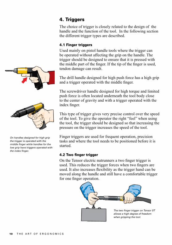
Used mainly on pistol handle tools where the trigger can be operated without affecting the grip on the handle. The trigger should be designed to ensure that it is pressed with themiddlepartofthefinger.Ifthetipofthefingerisused,tendon damage can result.
The drill handle designed for high push force has a high grip andatriggeroperatedwiththemiddlefinger.
The screwdriver handle designed for high torque and limited push force is often located underneath the tool body close to the center of gravity and with a trigger operated with the indexfinger.
This type of trigger gives very precise control over the speed of the tool. To give the operator the right “feel” when using the tool, the trigger should be designed so that increasing the pressure on the trigger increases the speed of the tool.
Finger triggers are used for frequent operation, precision tasks and where the tool needs to be positioned before it is started.
4.2 Two finger trigger
OntheTensorelectricnutrunnersatwofingertriggerisused.Thisreducesthetriggerforceswhentwofingersareused.Italsoincreasesflexibilityasthetriggerhandcanbemoved along the handle and still have a comfortable trigger foronefingeroperation.
On handles designed for high grip the trigger is operated with the middle finger while handles for the low grip have triggers operated with the index finger.
The two finger trigger on Tensor ST allows a high degree of freedom when gripping the tool.
11T H E A R T O F E R G O N O M I C S
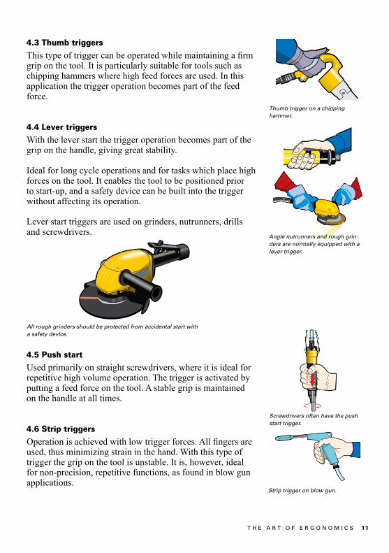
4.3 Thumb triggers
Thistypeoftriggercanbeoperatedwhilemaintainingafirmgrip on the tool. It is particularly suitable for tools such as chipping hammers where high feed forces are used. In this application the trigger operation becomes part of the feed force.
4.4 Lever triggers
With the lever start the trigger operation becomes part of the grip on the handle, giving great stability.
Ideal for long cycle operations and for tasks which place high forces on the tool. It enables the tool to be positioned prior to start-up, and a safety device can be built into the trigger without affecting its operation.
Lever start triggers are used on grinders, nutrunners, drills and screwdrivers.
4.5 Push start
Used primarily on straight screwdrivers, where it is ideal for repetitive high volume operation. The trigger is activated by putting a feed force on the tool. A stable grip is maintained on the handle at all times.
4.6 Strip triggers
Operationisachievedwithlowtriggerforces.Allfingersareused, thus minimizing strain in the hand. With this type of trigger the grip on the tool is unstable. It is, however, ideal for non-precision, repetitive functions, as found in blow gun applications.
Thumb trigger on a chipping hammer.
Strip trigger on blow gun.
Screwdrivers often have the push start trigger.
All rough grinders should be protected from accidental start with a safety device.
Angle nutrunners and rough grin-ders are normally equipped with a lever trigger.
12 T H E A R T O F E R G O N O M I C S
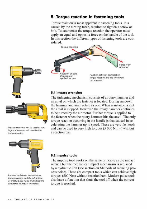
5. Torque reaction in fastening toolsTorque reaction is most apparent in fastening tools. It is caused by the turning force, required to tighten a screw or bolt. To counteract the torque reaction the operator must apply an equal and opposite force on the handle of the tool. In this section the different types of fastening tools are con-sidered.
5.1 Impact wrenches
The tightening mechanism consists of a rotary hammer and an anvil on which the fastener is located. During rundown the hammer and anvil rotate as one. When resistance is met the anvil is stopped. However, the rotary hammer continues to be turned by the air motor. Further torque is applied to the fastener when the rotary hammer hits the anvil. The only torque reaction occurring in the handle is that caused in ac-celerating the hammer up to speed. These are very fast tools and can be used to very high torques (5 000 Nm +) without a reaction bar.
5.2 Impulse tools
The impulse tool works on the same principle as the impact wrench but the mechanical impact mechanism is replaced by a hydraulic unit (see section on Methods of reducing pro-cess noise). These are compact tools which can achieve high torques (500 Nm) without reaction bars. Modern pulse tools also have a function that shuts the tool off when the correct torque is reached.
Torque reaction
Force fromoperator
Rotation of bolt.Direction ofapplied torque
Relation between bolt rotation, torque reaction and the force from the operator.
Impulse tools have the same low torque reaction and the advantage of creating less noise and vibrations compared to impact wrenches.
Impact wrenches can be used to very high torques and still have limited torque reaction.

13T H E A R T O F E R G O N O M I C S
5.3 Direct driven tools
Reaction force occurs primarily in direct driven assembly tools. The reaction force is generated by the torque applied to tighten the screw and must be absorbed by a torque arm/reac-tion bar, by the tool’s inherent inertia, or by the operator.
The operator’s capability to absorb torque depends on his or her muscular strength. Muscular strength depends, in turn, on factors such as the operator’s working posture and how fast the torque builds up. For very fast torque reactions, the tool inertia absorbs the reaction torque and the tighte-ning feels comfortable. If the tool inertia cannot absorb the reaction force for a fast tightening, it becomes jerky and uncomfortable. On the other hand, if the speed of the tighte-ning is slow enough, the operator can counteract the torque reaction in a controlled way and it becomes more comforta-ble. For a controllable torque reaction, the ”soft stop” feature should be used, if applicable.
To set limits for torque, it is necessary to take the above fac-torsintoconsideration.However,itisdifficulttostateagene-ral limit for when the torque reaction becomes too great to be absorbed by the operator. According to the safety standard for assembly tools, ISO11148-6, it should be possible to attach torque absorbing devices for the following torques:
- Straight tools, 4 Nm,- Pistol grip tools, 10 Nm- Angle tools, 60 Nm
However, in many cases, these torques can be too high to be absorbed manually.
5.3.1 Pneumatic shut-off tools
Pneumatic shut-off tools have a clutch mechanism built into the driveline. The clutch releases at a preset torque level and at the same time the air supply to the motor is shut off.
With a fast acting clutch the inherent inertia in the tool takes a large percentage of the reaction force. This only applies for very fast tightenings, which normally mean hard joints. The fast clutch simply helps to stop the torque build-up faster. Although not as compact as impact/impulse tools, pneumatic shut-off tools are relatively small and fast compared to stall tools.
Pneumatic angle tools are normally used up to 50 Nm without reaction bars.
14 T H E A R T O F E R G O N O M I C S
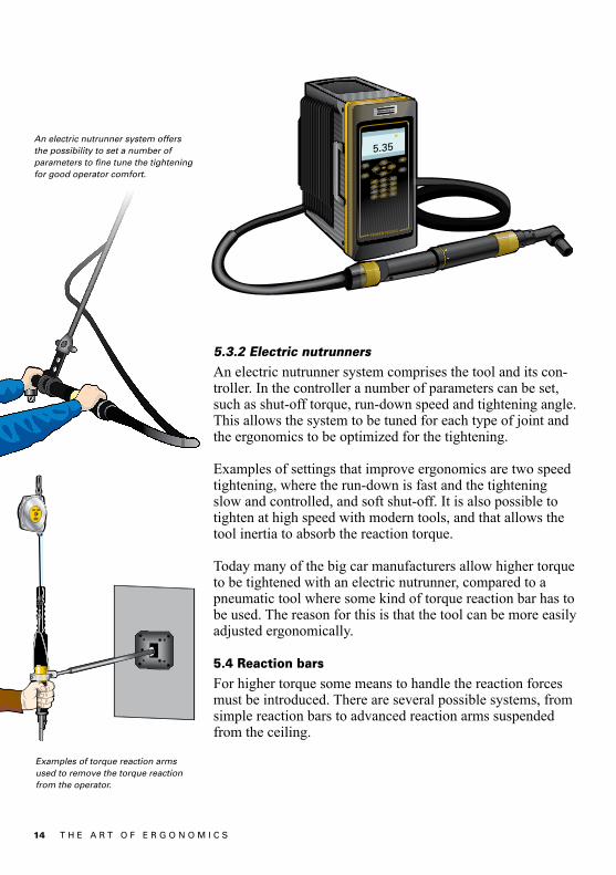
5.3.2 Electric nutrunners
An electric nutrunner system comprises the tool and its con-troller. In the controller a number of parameters can be set, such as shut-off torque, run-down speed and tightening angle. This allows the system to be tuned for each type of joint and the ergonomics to be optimized for the tightening.
Examples of settings that improve ergonomics are two speed tightening, where the run-down is fast and the tightening slow and controlled, and soft shut-off. It is also possible to tighten at high speed with modern tools, and that allows the tool inertia to absorb the reaction torque.
Today many of the big car manufacturers allow higher torque to be tightened with an electric nutrunner, compared to a pneumatic tool where some kind of torque reaction bar has to be used. The reason for this is that the tool can be more easily adjusted ergonomically.
5.4 Reaction bars
For higher torque some means to handle the reaction forces must be introduced. There are several possible systems, from simple reaction bars to advanced reaction arms suspended from the ceiling.
An electric nutrunner system offers the possibility to set a number of parameters to fine tune the tightening for good operator comfort.
Examples of torque reaction arms used to remove the torque reaction from the operator.

15T H E A R T O F E R G O N O M I C S
5.5 Balancers
Wherepossible,toolsshouldbefixedtobalancerstoreducethe strain on the worker, to prevent damage to the tool and to keep the work area tidy. There are two types of balancers from which to choose:
•Standardspringbalancer•Constanttensionbalancer
The standard spring balancer applies a force on the tool that retracts the tool to a stand-by position. This force increases the further the wire is extended. Every time the tool is used the operator has to overcome the load.
The constant tension balancer applies a constant force on the tool regardless of wire extension. This reduces the load on the worker. A drawback with this balancer is that the tool has to be consciously moved to the stand-by position.
Bench assembly of small electric devices is a typical application for screwdrivers supported in balancers.
Colibri balancer of the constant tension type.
RIL balancer of spring type.

16 T H E A R T O F E R G O N O M I C S
6. Sound6.1 What is sound?
Sound is the ear’s ability to detect variations in air pressure. The audible range is measured in units called decibels (dB). Sensitivity to sound is dependent on the frequency of pres-surevariation.Whenmeasuringsoundlevelsafiltersimula-tingthecharacteristicoftheearisused.Thisfilteriscalledthe“A”filter.SoundisusuallydescribedindB(A)indicatingthefilterhasbeenusedinsoundmeasurement.
6.2 How does sound affect us?
Continued exposure to high sound levels destroys the sound sensitive hair cells in the inner air which reduces hearing ability. To a certain extent the ear can protect itself against loud noise by dampening the movement of the bones in the middle ear. As this mechanism takes about 0.04 of a second to activate, impulse noises from tools such as impact wren-ches and riveting hammers can be particularly damaging.Since hearing is one of the brain’s main senses even relati-vely low levels of noise can be distracting. This can lead to loss of concentration and fatigue.
10000100010010
10
0
20
30
40
50
60
70
80
db
A
The dB(A) filter used in sound measurements.
Frequency, Hz

17T H E A R T O F E R G O N O M I C S
6.3 Measurement to establish noise emission values
Most pneumatic tool manufacturers use the ISO 15744 test method to measure the noise levels of their products. This method involves measuring the noise level (in an anechoic chamber) at 5 points around the tool. From this the noise emission level for the tool is obtained. Most types of tools are run under no load conditions with the supplied accesso-riesmounted.Thisisthevalueyouwillfindasthedeclarednoise level in the documents supplied with the tool.
This value is only an indication of the noise level that the operator will be exposed to in a real work situation. Because each tool can be used in many different applications it is impossible to predict what the process noise level will be.Also the distance from the tool to the operator’s ear can differ from the 1 meter used in the test.
For example, with screwdriving operations the machine noise will be the greatest source of noise in the workplace. However, when grinding the machine noise is only signi-ficantatstart-up,stoppingandduringunloadedrunning.During the grinding operation the process noise will be most significant.
6.4 Health and safety regulations
The health and safety regulations are most concerned with overall noise levels in the workplace. Although brief expo-sure to very high noise levels can cause pain and a perma-nent loss of hearing, it is prolonged exposure to relatively high noise levels that affects the majority of workers.
6.5 The Physical Agents (Noise) Directive
In February 2003 the European Parliament and Council published the Directive 2003/10/EC. This directive regulates how operators can be exposed to noise. The directive has been adopted into national law or regulations since February 15, 2006.
The directive introduces 3 values. The lower action value, the upper action value and the limit value. The values are expressed as 8 hour dose values in dB(A) and as peak values in dB(C).
Measurements according to ISO 15744 are made with 5 micro phones at a distance of 1 meter from the center of the tool.
18 T H E A R T O F E R G O N O M I C S
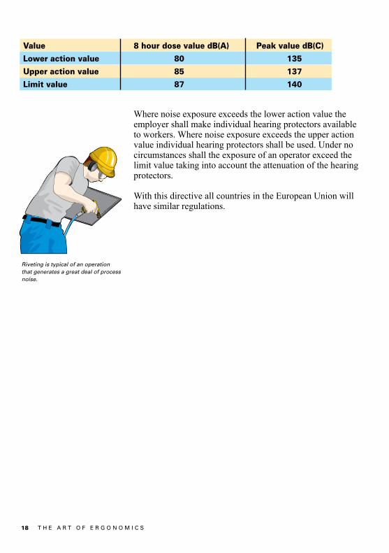
Where noise exposure exceeds the lower action value the employer shall make individual hearing protectors available to workers. Where noise exposure exceeds the upper action value individual hearing protectors shall be used. Under no circumstances shall the exposure of an operator exceed the limit value taking into account the attenuation of the hearing protectors.
With this directive all countries in the European Union will have similar regulations.
Value 8 hour dose value dB(A) Peak value dB(C)
Lower action value 80 135
Upper action value 85 137
Limit value 87 140
Riveting is typical of an operation that generates a great deal of process noise.
19T H E A R T O F E R G O N O M I C S
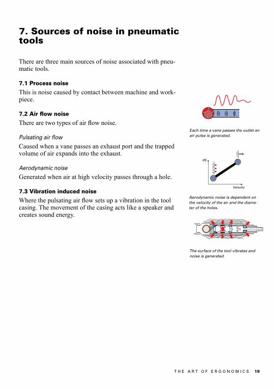
Each time a vane passes the outlet an air pulse is generated.
Aerodynamic noise is dependent on the velocity of the air and the diame-ter of the holes.
The surface of the tool vibrates and noise is generated.
7. Sources of noise in pneumatic tools
There are three main sources of noise associated with pneu-matic tools.
7.1 Process noise
This is noise caused by contact between machine and work-piece.
7.2 Air flow noise
Therearetwotypesofairflownoise.
Pulsating air flow
Caused when a vane passes an exhaust port and the trapped volume of air expands into the exhaust.
Aerodynamic noise
Generated when air at high velocity passes through a hole.
7.3 Vibration induced noise
Wherethepulsatingairflowsetsupavibrationinthetoolcasing. The movement of the casing acts like a speaker and creates sound energy.

20 T H E A R T O F E R G O N O M I C S
8. Methods of reducing noise
8.1 Process noise
Unfortunately with operations such as grinding, riveting and chippingitisverydifficulttoreduceprocessnoiselevels.In many cases the best solution is to isolate these processes from the rest of the factory and ensure that the operators in that area wear ear protection.
Forscalingapplicationsonesolutionistofixthechiseltothereciprocating piston. The shock wave that would have been caused when a piston hits the chisel is not present and hence noise levels are much reduced. The applications for this de-sign are limited because it has a relatively low impact force.
Scaling hammer with chisel fixed to piston.
A fastening tool that produces high process noise levels, is the impact wrench. Despite this these tools remain popular because of their high torque capacity and low reaction force. A solution to the noise problem has been found in the hy-draulic impulse tool. The mechanical impact mechanism has been replaced with a hydraulic impulse unit, which generates a smoother torque pulse, which causes much lower process noise levels.
Simplified layout of a hydraulic impulse tool.
Comparison between sound pressure levels produced in a structure by impact and impulse tools.
21T H E A R T O F E R G O N O M I C S
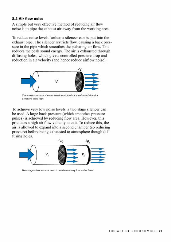
8.2 Air flow noise
Asimplebutveryeffectivemethodofreducingairflownoise is to pipe the exhaust air away from the working area.
To reduce noise levels further, a silencer can be put into the exhaustpipe.Thesilencerrestrictsflow,causingabackpres-sureinthepipewhichsmoothesthepulsatingairflow.Thisreduces the peak sound energy. The air is exhausted through diffusing holes, which give a controlled pressure drop and reductioninairvelocity(andhencereduceairflownoise).
To achieve very low noise levels, a two stage silencer can be used. A large back pressure (which smoothes pressure pulses)isachievedbyreducingflowarea.However,thisproducesahighairflowvelocityatexit.Toreducethis,theair is allowed to expand into a second chamber (so reducing pressure) before being exhausted to atmosphere though dif-fusing holes.
Two stage silencers are used to achieve a very low noise level.
The most common silencer used in air tools is a volume (V) and a pressure drop (Dp).
22 T H E A R T O F E R G O N O M I C S
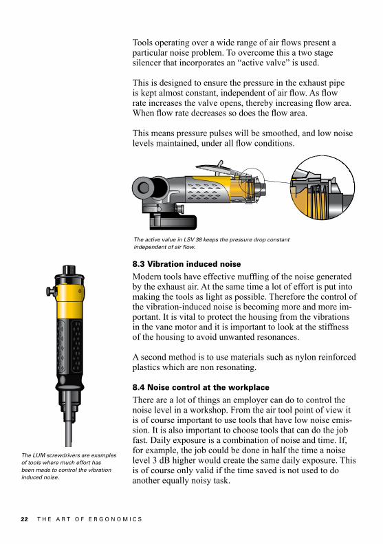
Toolsoperatingoverawiderangeofairflowspresentaparticular noise problem. To overcome this a two stage silencer that incorporates an “active valve” is used.
This is designed to ensure the pressure in the exhaust pipe iskeptalmostconstant,independentofairflow.Asflowrateincreasesthevalveopens,therebyincreasingflowarea.Whenflowratedecreasessodoestheflowarea.
This means pressure pulses will be smoothed, and low noise levelsmaintained,underallflowconditions.
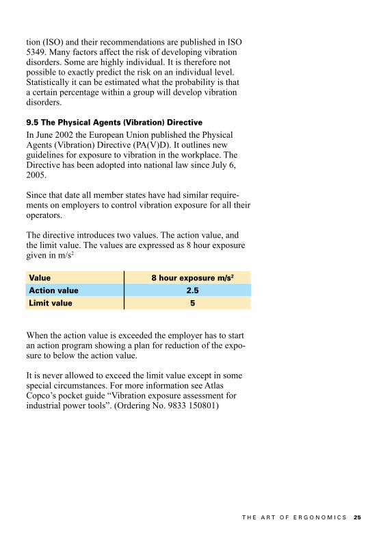
8.3 Vibration induced noise
Moderntoolshaveeffectivemufflingofthenoisegeneratedby the exhaust air. At the same time a lot of effort is put into making the tools as light as possible. Therefore the control of the vibration-induced noise is becoming more and more im-portant. It is vital to protect the housing from the vibrations in the vane motor and it is important to look at the stiffness of the housing to avoid unwanted resonances.
A second method is to use materials such as nylon reinforced plastics which are non resonating.
8.4 Noise control at the workplace
There are a lot of things an employer can do to control the noise level in a workshop. From the air tool point of view it is of course important to use tools that have low noise emis-sion. It is also important to choose tools that can do the job fast. Daily exposure is a combination of noise and time. If, for example, the job could be done in half the time a noise level 3 dB higher would create the same daily exposure. This is of course only valid if the time saved is not used to do another equally noisy task.
The LUM screwdrivers are examples of tools where much effort has been made to control the vibration induced noise.
The active value in LSV 38 keeps the pressure drop constant independent of air flow.

23T H E A R T O F E R G O N O M I C S
9. Vibrations in handheld tools
9.1 What is vibration?
Vibration is a means of describing how a body is accelerated by oscillating external or internal forces. These oscillating forces have different frequencies, depending on their source.
9.2 Why is vibration a concern?
Exposure to excessive levels of vibration can cause vascular injury, damage nerve cells and cause damage to the bones at the joints.
Vascularinjuryiswherethearteriesinthefingersthicken,therebyreducingflowareafortheblood.Theconditionis irreversible. This injury becomes apparent under cold temperatures where the body reduces blood supply to the extremities.Becauseoftherestrictedflowpaththebloodcannot pass through the affected areas and sensation is lost. Theaffectedfingersappearwhiteandthisphenomenoniscalledvibrationinducedwhitefinger(VWF).
Finger arteries on normal cross section and when affected by VWF.

24 T H E A R T O F E R G O N O M I C S
Nerve cells can be damaged by vibration and this is associa-tedwithalossofsensitivityinthefingers.
In the early stages the damage may be reversible but pro-longed exposure will cause permanent damage. This is the type of induced damage that gives rise to most complaints, because affected persons are restricted in their everyday acti-vities. Things like buttoning up a shirt, picking up coins from aflatsurfaceorsawingbecomedifficultorimpossibletasks.
Bone damage is caused by using tools that require high feed forces. The vibration is passed through the hand and arm causing wear and even fracturing at the joints.
9.3 Measurements to establish vibration emission
values
Vibration emission measurements used as the basis for the declared vibration values are made by using the ISO 28927 series of test codes. Corresponding test codes for electric tools can be found in the EN 60745 series. The main purpose of the measurements is to produce repeatable and reprodu-cible values that can be used to compare different tools from a vibration viewpoint. Present standards in the 28927 series use one or two accelerometer positions located between the thumbandtheindexfingerforthehand/handsincontactwith the tool. At each point measurements are made in three directions.
A declared value measured using the ISO 28927 series, or the EN 60745 series standards will, in most cases, be repre-sentative of the in-use vibration values which are likely to be experienced in the workplace when the tool is in normal use. According to CEN/TR 15350 a rough assessment can be made using the values obtained using the ISO 28927 series, or the EN 60745 series standards.
9.4 Health and safety regulations
Itisverydifficulttoquantifywhatexposuretimeandwhatamplitude and frequency of vibration causes the injuries described previously.
The most indepth analysis of vibration induced injuries has been made by the International Standardization Organisa-
25T H E A R T O F E R G O N O M I C S
tion (ISO) and their recommendations are published in ISO 5349. Many factors affect the risk of developing vibration dis orders. Some are highly individual. It is therefore not possible to exactly predict the risk on an individual level. Statistically it can be estimated what the probability is that a certain percentage within a group will develop vibration disorders.
9.5 The Physical Agents (Vibration) Directive
In June 2002 the European Union published the Physical Agents (Vibration) Directive (PA(V)D). It outlines new guidelines for exposure to vibration in the workplace. The Directive has been adopted into national law since July 6, 2005.
Since that date all member states have had similar require-ments on employers to control vibration exposure for all their operators.
The directive introduces two values. The action value, and the limit value. The values are expressed as 8 hour exposure given in m/s2
When the action value is exceeded the employer has to start an action program showing a plan for reduction of the expo-sure to below the action value.
It is never allowed to exceed the limit value except in some special circumstances. For more information see Atlas Copco’s pocket guide “Vibration exposure assessment for industrial power tools”. (Ordering No. 9833 150801)
Value 8 hour exposure m/s2
Action value 2.5
Limit value 5
26 T H E A R T O F E R G O N O M I C S
10. Sources of vibration
Tools for industrial use must be of very robust design towithstand the hard use they can be exposed to. From a vi-bration point of view this means that most tools can be regarded as rigid bodies. Oscillating forces act on this body and the result is vibration. The oscillating forces are either independent of the work process or process dependent forces.
The forces independent of the work process originatefrom, e.g., the imbalance of internal parts in rotating machi-nes or the imbalance of inserted tools. The forces necessary to accelerate the piston in a percussive tool are also examplesof this type of force.
Process dependent forces are generated, for example, when a grinding wheel is in contact with the workpiece or when the shockwaveinachiseltoapercussivetoolisreflectedbackinto the tool from the workpiece. The contact force between the bolt and the socket when an impact wrench is tightening a bolt is another example of a process dependent force.
In all cases we are talking about forces as the source ofvibration. This leads to the three basic principles to controlvibration:
• Controlthemagnitudeofthevibratingforces.Examples are the autobalancer on a grinder or the differential piston in a chipping hammer.
• Makethetoollesssensitivetothevibratingforces. Examples can be when the mass of the guard on a grinder is rigidly connected to the tool to increase its inertia.
• Isolatethevibrationsinthetoolfromthegripsurfaces. Examples are vibration-dampening handles on grinders or pavement breakers and the air-spring behind the blow- mechanism in a riveting hammer or the mass spring system in a chipping hammer.

27T H E A R T O F E R G O N O M I C S
11. Reducing vibration in handheld tools
11.1 Grinders
As grinders tend to be used over long periods of time it is important to reduce vibrations as much as possible.
The greatest source of vibration is the imbalance of the in-serted tool (grinding wheel, burr or mounted point). It is therefore important to always use well balanced inserted tools. It is also important that operators are informed not to use a grinder when a newly inserted tool causes excessive vibration. They should immediately scrap the inserted tool involved and use a new one instead.
11.2 Die grinders
Vibrations are caused by out of balance cutting burrs and by the grinding process itself. A method of reducing vibra-tion in the handle is to mount the motor and drive line in a weak suspension, which in this case are rubber elements. The vibrations are absorbed in the suspension and are not trans-mitted to the handle.
11.3 Angle and vertical grinders
Support handles can be used to control vibration in two differ ent ways. A rigidly mounted handle will move in phase with the housing. The inertia of the handle will help to reduce the rotation around the main handle.
A softly suspended handle will move out of phase. Its inertia is no longer part of the inertia of the occillating machine. The amplitude of the rotation of the tool around the main handle will increase but only a fraction of the vibration is transmit-ted to the support handle.
11.4 Turbo grinders
The turbo grinders GTG 40 and GTG 21 represent the state of the art in vibration control. The tools are 30 to 50% lower in weight compared to conventional grinders with similar power, and still they have vibrations that are considerably lo-wer than conventional tools. All existing techniques to reduce vibration have been used in the design.
Angle grinder LSV 38 with a support handle with a small extra weight stiffly mounted on the tool to reduce vibrations.
Die grinder LSF with soft suspension of the rotating parts.

28 T H E A R T O F E R G O N O M I C S
The oscillating forces have been reduced by using a spindle withaverystiffbearingconfigurationincombinationwithflangesthataremachinedtotighttolerances.Anautobalanceris also used. The autobalancer is a device located on the tool spindle that automatically counterbalances any imbalance of the wheel.
The tool has been made less sensitive to the oscillating forces by using as much as possible of the available mass in the tool to increase the inertia. On this tool the wheelguard is an important part of the inertia especially for rotation around an axis along the main handle. Therefore the guard is rigidly fixedtothetoolusingthepressureinthecompressedairwhen the tool is running. When the tool is not triggered there is no pressure and the guard can easily be moved.
The sensitivity to oscillating forces can also be reduced when the distance between the unbalanced forces from the wheel and the center of gravity of the tool is kept as small as possible.
Support handles with vibration isolation were also consi-dered but were rejected due to the fact that vibrations were already low and the decreased maneuverability was regarded as a major disadvantage.
11.5 Percussive tools
With all percussive tools there is a potential vibration source from the movement of the piston and from the changing air pressure that powers it. In a conventional percussive tool this vibration is transferred to the handle.
The turbo grinders GTG 40 and GTG 21 are designed using all possible means to reduce vibrations.
Spindle withhigh precision Support handle
Light weight to save 0.4 kg
Shortdistance
Guard locked under grinding
Autobalancer
Use thesleeve
Because the shockwaves in them cause vibration, the chisel or die should never be held.
29T H E A R T O F E R G O N O M I C S
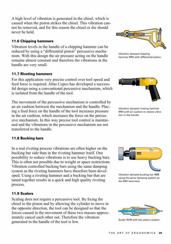
A high level of vibration is generated in the chisel, which is caused when the piston strikes the chisel. This vibration can-not be removed, and for this reason the chisel or die should never be held.
11.6 Chipping hammers
Vibration levels in the handle of a chipping hammer can be reduced by using a “differential piston” percussive mecha-nism. With this design the air pressure acting on the handle remains almost constant and therefore the vibrations in the handle are very small.
11.7 Riveting hammers
For this application very precise control over tool speed and feed force is required. Atlas Copco has developed a success-ful design using a conventional percussive mechanism, which is isolated from the handle of the tool.
The movement of the percussive mechanism is controlled by an air cushion between the mechanism and the handle. Plac-ing a feed force on the handle of the tool increases pressure in the air cushion, which increases the force on the percus-sive mechanism. In this way precise tool control is maintai-ned and the vibrations in the percussive mechanism are not transferred to the handle.
11.8 Bucking bars
In a real riveting process vibrations are often higher on the bucking bar side than in the riveting hammer itself. One possibility to reduce vibrations is to use heavy bucking bars. This is often not possible due to weight or space restrictions. Vibration controlled bucking bars using the same damping system as the riveting hammers have therefore been devel-oped. Using a riveting hammer and a bucking bar that are tuned together results in a quick and high quality riveting process.
11.9 Scalers
Scalingdoesnotrequireapercussivetool.Byfixingthechisel to the piston and by allowing the cylinder to move in the opposite direction, the tool can be designed so that the forces caused in the movement of these two masses approx-imately cancel each other out. Therefore the vibration generated in the handle of the tool is low.
Vibration damped riveting hammer RRH with air cushion to reduce vibra-tion in the handle.
Scaler RVM with two piston system.
Vibration damped bucking bar RBB using the same damping system as the RRH hammers.
Vibration damped chipping hammer RRD with differential piston.
30 T H E A R T O F E R G O N O M I C S
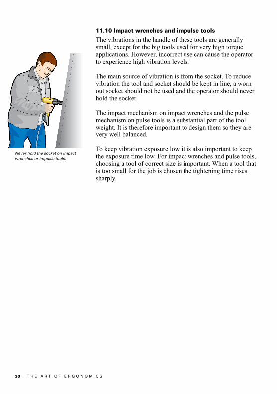
11.10 Impact wrenches and impulse tools
The vibrations in the handle of these tools are generally small, except for the big tools used for very high torque applications. However, incorrect use can cause the operator to experience high vibration levels.
The main source of vibration is from the socket. To reduce vibration the tool and socket should be kept in line, a worn out socket should not be used and the operator should never hold the socket.
The impact mechanism on impact wrenches and the pulse mechanism on pulse tools is a substantial part of the tool weight. It is therefore important to design them so they are very well balanced.
To keep vibration exposure low it is also important to keep the exposure time low. For impact wrenches and pulse tools, choosing a tool of correct size is important. When a tool that is too small for the job is chosen the tightening time rises sharply.
Never hold the socket on impact wrenches or impulse tools.

31T H E A R T O F E R G O N O M I C S
12. Lubrication-free motorsThese allow the working area to be kept free from oil contamination. This makes the working environment more pleasantandgivesgreatbenefitstooperatorswhohavesen-sitive skin. Lubrication-free motors also give a reduction in maintenance costs and ensure that no oil contamination of the product occurs.
32 T H E A R T O F E R G O N O M I C S
13. Dust control
13.1 Why control dust?
The dust from many materials is inert and causes no perma-nent damage. Even so, this dust can make working condi-tionsdifficultandunpleasant,whichcanaffectproductivity.
The dust from some materials, however, can be harmful and diseases such as cancer, silicosis, asbestosis and toxic poison-ing can result.
The sizes of dust particles that are of most concern are those below 5 microns (5 x 10⁻⁶ metres). Particles of this size can penetrate the body’s defence systems and reach the oxygen transfer areas in the lungs.
13.2 Health
Every country has its own national threshold values of allowable dust levels for different materials. These levels are constantly under review. Many new materials are being in-troduced each year and added to the list of threshold values.
13.3 How to control dust
There are a number of methods of ensuring that the operator is not exposed to dust when using hand-held tools. The work bench can have extraction openings connected to a strong vacuum source, a movable extraction hood can be used and thetoolitselfcanbefittedwithanextractionsystem.Inextreme cases the operator can wear breathing apparatus as an additional protection.
Of the dust collection methods, dust extraction on the tool is themostefficientascollectionisatthepointofdustcrea-tion.Thisnotonlyensuresveryefficientextractionbutalsoallows a relatively low power vacuum source to be used.
33T H E A R T O F E R G O N O M I C S
14. Extraction systems for tools
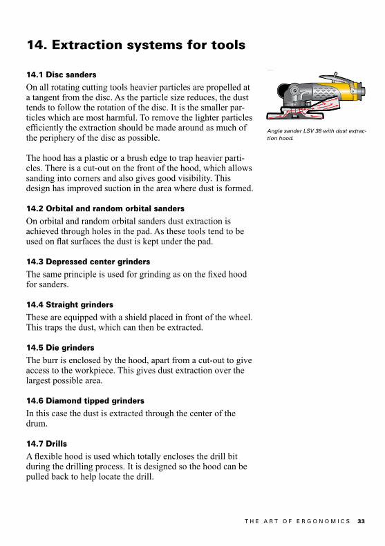
14.1 Disc sanders
On all rotating cutting tools heavier particles are propelled at a tangent from the disc. As the particle size reduces, the dust tends to follow the rotation of the disc. It is the smaller par-ticles which are most harmful. To remove the lighter particles efficientlytheextractionshouldbemadearoundasmuchofthe periphery of the disc as possible.
The hood has a plastic or a brush edge to trap heavier parti-cles. There is a cut-out on the front of the hood, which allows sanding into corners and also gives good visibility. This design has improved suction in the area where dust is formed.
14.2 Orbital and random orbital sanders
On orbital and random orbital sanders dust extraction is achieved through holes in the pad. As these tools tend to be usedonflatsurfacesthedustiskeptunderthepad.
14.3 Depressed center grinders
Thesameprincipleisusedforgrindingasonthefixedhoodfor sanders.
14.4 Straight grinders
These are equipped with a shield placed in front of the wheel. This traps the dust, which can then be extracted.
14.5 Die grinders
The burr is enclosed by the hood, apart from a cut-out to give access to the workpiece. This gives dust extraction over the largest possible area.
14.6 Diamond tipped grinders
In this case the dust is extracted through the center of the drum.
14.7 Drills
Aflexiblehoodisusedwhichtotallyenclosesthedrillbitduring the drilling process. It is designed so the hood can be pulled back to help locate the drill.
Angle sander LSV 38 with dust extrac-tion hood.
34 T H E A R T O F E R G O N O M I C S
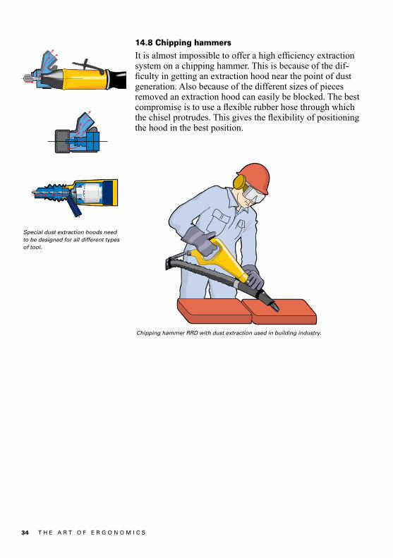
Special dust extraction hoods need to be designed for all different types of tool.
Chipping hammer RRD with dust extraction used in building industry.
14.8 Chipping hammers
Itisalmostimpossibletoofferahighefficiencyextractionsystem on a chipping hammer. This is because of the dif-ficultyingettinganextractionhoodnearthepointofdustgeneration. Also because of the different sizes of pieces removed an extraction hood can easily be blocked. The best compromiseistouseaflexiblerubberhosethroughwhichthechiselprotrudes.Thisgivestheflexibilityofpositioningthe hood in the best position.

35T H E A R T O F E R G O N O M I C S
15. Vacuum sources
There are basically three choices of vacuum source.
•Selfgeneratingvacuumsource•Portablevacuumsource•Centralvacuumsource
Tools with a self generating vacuum have the lowest set up costandoffergreatflexibility.However,theextractionstrength is low compared with the other methods. Also when the air supply to the motor is shut off the vacuum in the suc-tion hood and in the collecting bag is lost.
Thismeanstheefficencyofextractionislowcomparedwithother methods.
Portable units provide a strong vacuum for 1 or 2 tools. Theyareidealforsmallworkshopsandforflexibleworkingconditions. The initial set-up cost is low, but the units take up workspace and the vacuum unit must be kept close to the tool.
Acentralvacuumsourceisusedwheretherearefixedwork-stations. This can provide a very strong vacuum and the dust can be easily collected. The system keeps the work area clear. However, the initial set-up cost is high.
Self generating vacuum source.
Portable vacuum source.
Central vacuum system.

36 T H E A R T O F E R G O N O M I C S
Graph showing the relation between pressure drop (Dp) and flow for various diameters and lengths of spiral reinforced suction hoses.
15.1 Installation of extraction systems
Forefficientdustextractionthedesignedflowratethroughthe extraction hood must be maintained. For handheld tools this is usually between 150 and 250 cubic meters an hour.
When selecting the vacuum source the number of tools that will be used, and their required extraction rate, must be known. In addition, the losses in the pipes and hoses must be calculated.
Using the diagram below the pressure loss in different lengths and diameters of extraction pipe can be seen.

37T H E A R T O F E R G O N O M I C S
Forexample,assumingasingletoolrequiringaflowof200cubic meters per hour is connected to a vacuum source through a 5 meters, 1 1/2 inch diameter, pipe.
From the graph it can be seen that the pipe will cause a pres-sure drop of 1 800 mm water gauge. In addition, there will be a further pressure drop generated in the extraction hood, couplings,filters,etc.Thiswillbearound500mmwatergauge.
Therefore for this application the vacuum source must main-tain an extraction rate of 200 cubic meters an hour at 2 300 mm water gauge.
It might be necessary to use the same tool and vacuum source but, for example, over a length of 10 meters. In this case, a suitable hose would be one that has a diameter of 2 inches, over 7 meters, and a diameter of 1 1/2 inches over 3 meters.
To make a tool easy to use the extraction hose should be small and light but unfortunately a small hose causes a large pressure drop. The best solution is to keep the distance between the tool and the main pipework, or portable vacuum unit, as short as possible and to thin the hose near the tool. (This as the reason for calculating the pressure drop over two lengths of pipe in the previous example). It is also important to join the extraction hose and air supply hose together. If thisisnotdonethehandlingofthetoolismadeverydifficult.
To design a complete centralized system many other factors need to be considered which are outside the scope of this pocket guide. We recommend that you ask for expert advice if a centralized system is required.

38 T H E A R T O F E R G O N O M I C S
Atlas Copco Pocket Guides
Title Ordering No.
Air line distribution ................................................... 9833 1266 01
Air motors ................................................................. 9833 9067 01
Cable management .................................................. 9833 1640 01
Drilling with hand-held machines ........................... 9833 8554 01
Error proofed production ......................................... 9833 1437 01
Grinding ..................................................................... 9833 8641 01
Percussive tools ........................................................ 9833 1003 01
Pulse tools ................................................................. 9833 1225 01
Riveting technique .................................................... 9833 1124 01
Screwdriving ............................................................. 9833 1007 01
Statistical analysis .................................................... 9833 8637 01
Testing and calibration in assembly technology .... 9833 1720 01
The art of ergonomics .............................................. 9833 8587 01
Tightening technique ................................................ 9833 8648 01
Vibrations in grinders ............................................... 9833 9017 01
Vibration exposure assessment for power tools ... 9833 1508 01
Power Tool Ergonomics (book) ............................... 9833 1162 01

39T H E A R T O F E R G O N O M I C S

9833
858
7 01
R
ecyc
lab
le p
aper
. Jet
lag
/Bo
ard
wal
k 20
13:1
. TR
Try
ck
www.atlascopco.com