the application of gas chromatography to the analysis of
TRANSCRIPT

NPS ARCHIVE1966BEERS, R.
iHMlHXSIB
n&BraflH^^HL -
THE APPLICATION OF GAS CHROMATOGRAPHYTO THE ANALYSIS OF CERTAIN
HYDROCARBON FUELS
ROBERT CLEVE BEERS
^^^^^W

DUDLEY KNOX LIBRARY^^^m^S navaI postgraduate school
U. S. Naval Portgraih-H WB»o.MONTEREY, CA 93943-51 01
Gbrary
U. S. Ni
Monterey. California

This document has been approved for publicrelease and sale; its distribution is unlimited.


THE APPLICATION OF GAS CHROMATOGRAPHY
TO THE ANALYSIS
OF CERTAIN HYDROCARBON FUELS
by
Robert Cleve Beers
Lieutenant ..Commander, TJnited States NavyB.A. , University of Pennsylvania, 1953
Submitted in partial fulfillment
for the degree of
MASTER OF SCIENCE IN CHEMISTRY
from the
UNITED STATES NAVAL POSTGRADUATE SCHOOLMay 1966

ABSTRACT
As part of an investigation of gas turbine regenerator fouling
being conducted at the U. S. Naval Postgraduate School gas chroma-
tography was used to compare and analyze certain hydrocarbon fuels
.
Because of the known relationship between fuel aromaticity and
exhaust system fouling in gas turbine engines, particular emphasis
was directed toward determination of the aromaticity of the fuels and
of the particular aromatic compounds present. Fuels investigated in-
cluded premium grade auto gasoline, aviation gasoline, several gas
turbine fuels, and marine diesel fuel. Derivatives of cyclohexane
and decahydronaphthalene were synthesized by hydrogenation of ben-
zene and naphthalene derivatives with Raney nickel catalyst. Num-
erous branched-chain paraffins were synthesized by hydroisomerization
of n-olefins under alkylation conditions . These synthetic products
were used as standards in the identification of components of the
fuels. The fuels investigated were found to contain from 35 to
over 200 components. Component identification was from 30 to 60%
complete
.

DUDLEY KNOX LIBRARYt
I
NAVAL POSTGRADMONTEREY, CA 93
TABLE OF CONTENTS
Section Page
1. Introduction 9
2. Historical 10
3. Experimental 11
4. Presentation and Discussion of Data 19
5. Conclusions and Acknowledgements 36
6. Bibliography 38


LIST OF TABLES
Table Page
I Representative Hydrocarbon Fuels In-
vestigated 9
II Instrument Parameters for ChromatographicExperiments 12
III Results of Fuel Hydrogenations (3000 psi,
250°C) 19
IV Results of Mild Fuel Hydrogenations (50 psi,
22° C) 20
V Results of Individual Hydrogenations 24
VI Summary of Component Identification 27
VII Key for the Component Identification of
the Peaks on Fuel Chromatograms 2 8

LIST OF ILLUSTRATIONS
Figure Page
1. Column Temperature Program Profiles 13
2 . Isothermal vs Temperature ProgrammedSeparation of n-Alkanes 14
3. Component Identification Procedures 16
4. Washing Apparatus for Raney Nickel 18
5 . Experimental Apparatus for Hydroisomeri-zation Reactions 18
6. Chromatograms of Hydrogenations 21
7. Chromatograms of Hydrogenations 22
8. Chromatograms of Hydrogenations 23
9. Chromatograms of HydroisomerizationProducts 2 6
10. Fuel Chromatograms on SE30 Packed Column 33
11. Fuel Chromatograms on SE30 Packed Column 34
12. Fuel Chromatograms on DC550 Capillary
Column 35


1 . Introduction
The rapid advances made in the field of gas chromatography in
recent years have dramatically expanded the researcher's ability to
analyze very complex mixtures of chemical compounds.
The analysis and comparison of several representative hydro-
carbon fuels (Table I) were undertaken, not only an overall comparison,
but a partial component analysis as well. This analytical work was
made possible only through the use of an extremely sophisticated gas
chromatography the Beckman model GC-4. This gas chromatograph
provides for carefully controlled linear temperature programming and
is equipped with a highly sensitive hydrogen flame ionization detector.
The GC-4 also uses a dual - or reference - column mode of operation
which eliminates the typical base-line drift and noisy operation at the
high temperatures required for the analysis.
Particular attention was given to the aromatic compounds and to
the overall aromaticity of the fuels, since it has been shown [3,4,
15 ] that the residue formation and sooting of these fuels can be
directly attributed to their aromatic content.
Identification of the individual components was made exclusive-
ly by comparison of retention times, hydrogenation of aromatics,
and/or the standard addition method. No attempt was made to iso-
late and identify individual components of these complete mixtures,
containing from 35 to over 200 components (Table I).
Fuel
TABLE I
Representative Hydrocarbon Fuels Investigated
Component boiling
range
Number of
Components
Premium Gasoline
Aviation Gasoline
JP4 Gas Turbine fuel
JP5 Gas Turbine fuel
25° C - 230° C
25° C - 195° C
25° C - 287.5° C
98.5° C - 303° C
Canadian Gas Turbine fuel 98.5° C - 330° C
Marine Diesel fuel 98,5° C - 350° C
9
83+
35+
114+
175+
200+
200+

Reference standards for the analysis were procured from three
sources: (l) Commercially available chemically pure compounds; (2)
Hydrogenation over Raney nickel catalyst of aromatic compounds to
yield substituted cyclohexanes , decahydronaphthalenes , and various
other saturated analogs of aromatic compounds; (3) Hydroisomerization
of normal olefins under alkylation conditixuiES to yield numerous
branched-chain alkanes.
2 . Historical
As early as 1947 Jonash, Barnett, and Strieker [9 ] had investi-
gated the problem of carbon deposition in gas turbine engines, ex-
perimenting with a full size jet propulsion engine and burning fuels
available at that time. These fuels were complex hydrocarbon mixtures,
and the effect of change in one fuel property at a time could not be
determined. The work of Jonash and Wear [15 ] and later Busch [4 ]
established the clear correlation of aromaticity to carbon deposition.
Bert has shown in his work at California Research Corp. [3 ] that the
most offensive aromatics were the naphthalenes and the highly alky-
lated benzenes. He also demonstrated the relative clean burning
properties of the paraffins and naphthenes.
Kohler and Miller [10 ] , supported by Bureau of Ships, Code 645,
conducted an extensive investigation into the fouling effects in com-
pact gas turbine regenerator matrices. This work is continuing at
the U. S. Naval Postgraduate School. The research reported herein
is in support of this fouling investigation.
Several recent advances in gas chromatography have indicated
the possibility of analyzing the complex fuels used in gas turbine
engines. Temperature programming [11, 12 ] of capillary columns
[8 ] is now routine. The sensitive hydrogen flame ionization detector
[5 ] and dual column operations [7 ] are also of signifigance . Albert
[2 ] analyzed the gasoline portion of petroleum with a combination of
gas chromatographic and molecular sieve techniques. Schwartz and
Brasseux [14 ] , among others, have used capillary columns to analyze
10

a relatively narrow petroleum cut. It was the purpose of this work to
apply temperature programming, high temperature capability, hydrogen
flame detection, and dual column operations to the analysis of a
representative group of highly complex fuels (Table I).
3 . Experimental
Gas Chromatography (GC)
A Beckman model GC-4 gas chromatograph was used in this' work.
This instrument combines the most advanced features in a high per-
formance, modular package. Some of its characteristics are:
1 . A well designed column compartment, featuring high velocity,
uniform air flow, substantially reducing temperature gradients.
2. A temperature programming module, which makes possible a
wide variety of precise linear and non-linear temperature programs,
as well as isothermal operation. This module utilizes a Mylar pro-
gramming sheet on which the temperature profile is traced with me-
tallic tape . By optically tracking the tape with a photoelectric curve
follower, the profile is converted into temperature.
3. A dual-hydrogen flame ionization detector of high sensitivity.
Use of this type of detector allows sample size to be reduced by
several orders of magnitude from that required by a thermal conduc-
tivity detector. This makes possible the use of a capillary column,
which would be saturated by a sample size normally used with packed
columns
.
4. The use of dual columns. In gas-liquid chromatography, bleed-
ing of the liquid phase is unavoidable. The column effluent always
contains a certain amount of this bleed. Since the detector will re-
spond to this substrate bleeding, a background signal is generated.
If column temperature and flow rate are constant, (isothermal oper-
ation) the rate of bleeding is constant and the background signal can
be electrically compensated. During temperature programmed operation,
however, a linear column temperature rise leads to an exponential
increase incthe vapor pressure of the liquid substrate. This increases
II

the background signal in the same way, producing unwanted baseline
drift. In the GC-4 two matched columns can be employed in conjunc-
tion with the dual hydrogen flame detectors . Since the column bleed
is then essentially balanced, the detector system sees no differential
between the two signals, and base-line stability results.
5. Ability to operate at high temperatures. Temperatures up to
500° C are possible in the column oven, inlet, and detector compart-
ment. This capability is vital, since the higher molecular weight
hydrocarbons investigated had boiling points as high as 400° C.
Both a conventionally packed column and capillary column were
used:
350° C
Substrate Solid
Support
Column I.D. o.o. Length Source ]\
SE 30 Acid Stainless .10" .125" 12' Beckman(20% wt) washed
DMDSChromo-sorb W
steel Instrument
Co.
DC 550 capil- stainless .01" .0625" 200' Perkin-
lary steel Elmer
column Corp.
160° C
Instrument conditions were experimentally adjusted to optimize the
resolution of compounds with boiling points ranging from 100° C to
300° C, at the same time affording reasonable resolution of the lower
boiling components (below 100° C) (Table II).
TABLE II
Instrument Parameters for Chromatographic Experiments
Parameter Column I
(SE 30)
Column 2
(DC 55 0)
He flow rate (cc/min) 35 4
He make-up (cc/min) 85 85
Air (cc/min) 275 275
Hydrogen (cc/min) 55 55
Detector Temp (° C) 275 275
Column flash vaporizor (°c) 230 175
Recorder speed (in/hr) 40 40
Sample size (ul) 0.3-1.2 0.3-1 .2
Split ratio none 33:1
Temperature program gradient (see fig. 1) 5°/min 2 . 2°/min
12

Because of its low flow rate of carrier gas and the length of the
capillary column, separate temperature profiles were necessary for
each type of column. These profiles are shown in Figure 1. Curve 1
of Figure 1 represents the program used with the 12' SE 30 Columns,
while curve 2 shows the temperature program for the DC 550 capillary
column.
-300°C
ZTO*
-200*0
/60°
-\00X ^^ ^—Z^?/M ,f/
70° /1 : \ t— \
so" _^--~
»\
10 TIME £0 (*\*l) 30 40 SO 60
FIGURE 1 COLUMN TEMPERATURE PROGRAM PROFILES
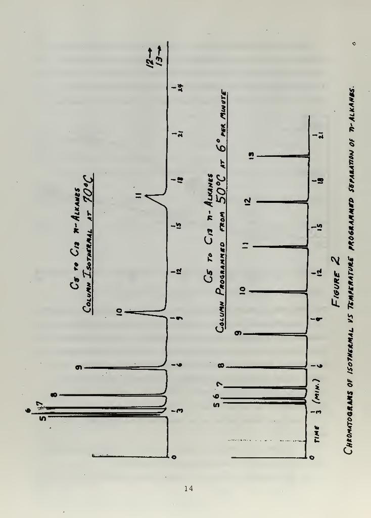
The advantage of temperature programming is shown in Figure 2 . Figure
2 is a comparison of the chromatograms of a mixture of n-alkanes,
isothermal vs temperature programmed operation. The chromatograms
were taken on the DD 550 capillary column. The first chromatogram
demonstrates typical isothermal elution of a homologous series, with
elution times increasing exponentially. The second chromatogram is
of the same mixture, but programmed from 50° to 140° C at 6°/nnn.
The members of the series elute in a linear manner after n-nonane
.
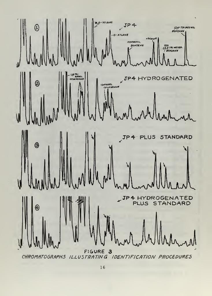
Component identification inithe fuels was accomplished in three
ways:
1 . Comparison of retention times of a library of known compounds
with unknown peaks in the chromatogram of the fuel.
2. Hydrogenating the fuel over Raney nickel catalyst, then observing
13
is
I!i
•4
i
=<-.*>
-a
9%
-,'.'—
UV
J3-
fc—
.
•J
lb
s
w is
s
!
c3
14

the differences in the chromatogram after hydrogenation. All aromatic
compounds are saturated by the reaction, and the saturated analogs elute
at different times than the parent aromatic.
3. The standard addition method. A small amount of known com-
pound which is believed to be contained in the fuel (from the methods
above) is added to the fuel, and its chromatogram examined for a pro-
portional peak-height increase. Figure 3 illustrates several examples
of these techniques . In trace 1 several peaks of JP4 are tentatively
identified by comparison of retention times . Trace 2 shows JP4 after
hydrogenation. The suspected peaks corresponding to isopropyl benzene
and 1,2, 4-trimethyl benzene have been reduced in size, as would
occur if they were aromatic. (The peak for n-decane remains unchanged.)
Additionally, the peaks corresponding to the cataloged positions of
isopropyl ccyclohexane and the four isomers of 1 , 2, 4-trimethyl
cyclohexane have all increased in relative size. Trace 3 shows JP4
to which a small amount of the tentatively identified compounds has
been added. The peaks for isopropyl benzene, 1,2, 4-trimethyl
benzene, and n-decane have all increased in relative size. Finally,
trace 4 shows the hydrogenated JP4 to which a small amount of separately
prepared isopropyl cyclohexane and 1,2, 4-trimethyl cyclohexane has
been added. The corresponding peaks are all increased in relative size.
From this four-step procedure, the peaks for both aromatics are firmly
identified. In addition, it can be concluded that the original JP4
contained the cyclohexane analogs.
Preparation of Raney Nickel Catalyst [1 ]
In a one liter filtering flask equipped with a thermometer and a
mechanical teflon stirrer, are placed 160 grams of sodium hydroxide in
a 600 cc of distilled water. The resulting solution is cooled to 50° C
in an ice bath. Then 125 grams of powdered Raney nickel-aluminum alloy
is added with constant stirring in small portions over a period of 30-40
minutes , while maintaining the temperature below 55° C. The suspension
is then digested at 50° C for one hour with constant stirring. The ice-
15
(2,4a Turnermu
4
IAaIk^aA^
JP^ PLUS STANDARD
JP4- HYDROGENATEDPLUS STANDARD
FIGURE 3CHR0mT0GRriPH5 ILLUSTRATING IDENTIFICATION PROCEDURES
16

bath is removed during this period and replaced with a warm-water bath
to maintain the temperature.
After digestion is complete, the catalyst is washed three times by
decantation. The catalyst is then washed with a continuous flow of
tap-water until the washings are neutral to indicator paper. Washing
is then continued for another 30 minutes. The total wash time is about
l£ hours. The Apparatus for washing is illustrated in Figure 4. The
stirrer is operated at a speed which suspends the catalyst to a height
of about 3 inches. Wash water flows through the system at about 50
cc/min.
After the washing is complete, the water is decanted from the
settled sludge of Raney nickel. The catalyst is then washed three times
by stirring with 150 ml at 95% ethyl alcohol, decanting after each
addition. The catalyst is then washed three times with absolute ethyl
alcohol. The catalyst is stored in a refrigerator in a cork-stoppered
bottle filled with 95% ethyl alcohol. The catalyst maintains its
activity for extended periods of time. A batch prepared 10 January, 1966
was still quite active when used on 20 April 1966.
Hydrogenation of Organic Compounds
The Raney nickel produced was used to catalyze the reduction of
a series of aromatic compounds , producing a new series of reference
standards for use in component identification. JP4, JP5, and Marine
Diesel Fuel were also hydrogenated in order to determine aromatic
content. The hydrogenatives were carried out in a Parr pressure re-
action apparatus (Parr Instrument Co . , Inc., Moline, Illinois). The
substance to be hydrogenated was placed inside a pyrex liner along
with 2-3 grams of catalyst, and the liner was then sealed inside the
stainless steel pressure vessel. The vessel was purged of air with
hydrogen, then was pressurized to 2000 psi hydrogen. The hydro-
genations were carried out at various temperatures and for varying
lengths of time. The absorption of hydrogen was in every experiment
within ±10% of that required for the formation of the saturated analogs.
1?

Attempts were made to partially hydrogenate various aromatic compounds
In each case, only the unreacted aromatic and the completely saturated
analog were found.
The resulting products from the hydrogenation reaction were then
gas chromatographed to determine purity, and the extent of reaction,
where reaction was not allowed to go to completion. Cis and trans
isomers were identified as such on the basis of boiling points, when
known. Before including any of the reaction products in the library
of reference standards, their infrared spectra were examined to confirm
their complete saturation.
Hz0 in
[0^
FIGURE 4- WASHING APPARATUSFOR RANEY NICKEft-
/V N?
FIGURE 5EXPERIMENTAL APPARATUS FOR.
HYDROISOMERUATIOM REACTIONS
Hydroisomerization of n-olefins
The hydroisomerization of n-olefins to isoparaffins and the coup-
ling of the isoparaffins used as hydrogen donors have been studied
by Peterson, Phillips, and Kelly. [13 ] This method of alkylation
of isopentane and isobutane with n-olefins has long been a commercial
process for producing high octane gasoline.
18

The overall reaction results in a mixture of isomers of the paraffin
resulting from the olefin , coupling products of the isopentane with
itself or with the heavier isoparaffins present, disproportionation pro-
ducts, and products of cracking. Hence the resulting product mixture
is quite complex. If the isopentane is in large excess, polymerization
is surpressed and the olefin reacts completely.
The reaction is carried out in a one liter, three necked pyrex flask
fitted with a mechanical stirrer, a thermometer, and a measuring flask
or funnel for introducting the olefin. The reaction vessel (Figure 5) is
charged with 100 cc of 97% weight sulfuric acid and 100 cc of isopentane,
The mixture is maintained at 22°C ±2°C. Addition of a mixture of
100 cc isopentane and 0.5 moles n-olefin was begun through the meas-
uring flask. The addition rate is maintained so as to add the entire
mixture over a period of 30 minutes. Stirring is continued for five
minutes after completion of the addition. The organic phase is then
separated. Any acid remaining is removed from the organic phase by
swirling with sodium hydroxide. The organic phase is then washed
sufficiently with water to remove any soaps which may have formed.
Washing is continued until the organic layer gives a neutral reaction
to indicator paper. The product mixture is then examined gas chro-
matographically. Completeness of reaction is confirmed if both the
chromatogram and the infrared spectra indicate absence of the n-olefin.
4. Presentation and Discussion of Data
The hydrogen of JP4, JP5 , and Marine Diesel Fuels provides an
overall comparison of their aromaticity. Table III summarizes the
results of these hydrogenations:
Table III
Results of Fuel Hydrogenations. (3000 psi, 250° C)
Run Fuel Sample Catalyst Time Moles H a consumedferns] (gms) (hrs) per gram of fuel
3 JP4 20 2 24 .0102
2 JP4 20 2 36 .0105
5 JP4 20 4 36 .0105
19
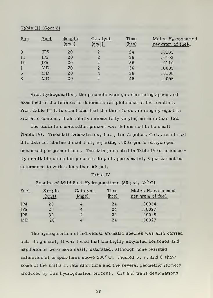
Table HI (Cont'd)
Run Fuel Sample Catalyst Time Moles H n consumed(gms) (gms) (hrs) per gram of fueld
9 JP5 20 2 24 .010511 JP5 20 2 36 .010510 JP5 20 4 36 .01101 MD 20 2 36 .00956 MD 20 4 36 .01008 MD 20 4 48 .0095
After hydrogenation, the products were gas chromatographed and
examined in the infrared to determine completeness of the reaction.
From Table III it is concluded that the three fuels are roughly equal in
aromatic content , their relative aromaticity varying no more than 15%
The olefinic unsaturation present was determined to be small
(Table IV). Truesdail Laboratories, Inc., Los Angeles, Cal". , confirmed
this data for Marine diesel fuel, reporting .0003 grams of hydrogen
consumed per gram of fuel. The data presented in Table IV is necessar-
ily unreliable since the pressure drop of approximately 5 psi cannot be
determined to within less than ±5 psi.
Table IV
Results of Mild Fuel Hydrogenations (50 psi, 22° C)
Fuel Sample Catalyst Time Moles H a consumed(gms) (gms) (hrs) per gram of fuel
JP4 20 4 24 .00054
JP5 20 4 24 .00027
JP5 30 4 24 .00029MD 20 4 24 .00027
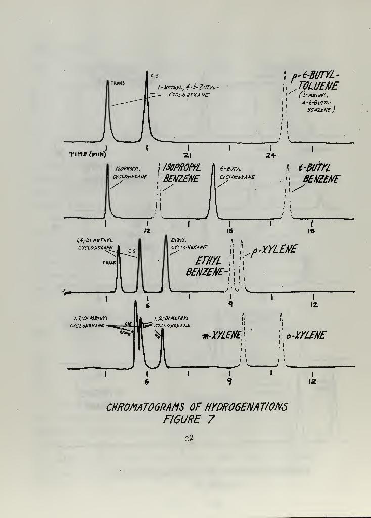
The hydrogenation of individual aromatic species was also carried
out. In general, it was found that the highly alkylated benzenes and
napthalenes were more easily saturated, although none resisted
saturation at temperatures above 200° C. Figures 6,7, and 8 show
some of the shifts in retention time and the several geometric isomers
produced by this hydrogenation process. Cis and trans designations
2D

2,3, D/-A1ETHYL-
DECAHYPRO-NAPHTHALEME
7U_/\__JUTine (mih)
I
33
2S-DI/1EWL i
NAPHTHALENE^}
^j
I METHYL - OECAHYDRO-fl/APHTHALEHE
iI
Z METHYL- DECAHYPRO-NAPHTHALEtiE
I
zw/iethylNAPHTHALENE-
i I
METHYLNAPHTHALENE^
i \
si
l
46
I
4k
METHYL,/NAPTHALENE
I
4a.
PI-CYCl-OUEY.iL
P1ETHAME
BIPHENYLDlPHENYL
/1EMA/I/E
d i*/ \
I
45I
51
CHR0MAT06RAMS OF HYDROGENATIONSF16URE 6
2-1
/ -mewl, 4 - 1-Butyl
CYCLbHEYAUE
I
n
ii
p
i!i
i
/ i
J !
p-i-BUTYL-rTOLUENE(i-nsTrtL,
4"i-BUTYL-
BEH2£Nt)
I
Tine(nm)I
2.1
< mp/tom.BENZENE
I
24-
ETVYL
CYCLDUEYAfter
i-BVTYL
CyCUXleYANE
I
* i-BumBENZENE
{
16
EWLBENZENE-
+ XYLENE
i
u'v^.i
LZrP'MKTMYL
CYCLOHCYAME-
m-XX£//£"
!!
i l
I i
I i
I i
I \
o-XYLENE
1
1
i \^I I
12
CHROMAT GRAMS OF HYDR06ENAV0N5FIGURE 7
22

I
1 M£TA-y PARA
Dl ISOPROPYLCyCLOHEXANE -DHSOmOWL BENZENE
1,3.5,-TRIMETHYL
CYCLoH£XANE
/M-rmmYLBENZENE.
i
9I
12I
CHR0WIT06RMS OF HYDOGENATIQNSFIGURE 8
23

are applied to isomers when boiling point data is available. The results
of these hydrogenations are summarized in Table V.
Table V
Results of Individual Hydrogenations
Compound Saturated Isomers Isomers ResolvedAnalog Expected Found SE3'0ffColumn/DC550
Ethyl benzene Ethyl cyclohexane 11-p-Xylene
m-Xylene
o-Xylene
1,4-Dimethylcyclohexane
1,3-Dimethylcyclohexane
1,2-Dimethylcyclohexane
1,3,5-Tri- 1,3,5-Trimethyl
methyl benzene cyclohexane
1,2,4-Tri- 1 ,2,4-Trimethyl
methyl benzene cyclohexane
yes
yes
yes
yes
no
yes
yes
yes
yes
yes
Isopropyl Isopropyl
benzene cyclohexane
t- Butyl t-Butyl
benzene cyclohexane
Diethyl Diethyl
benzene cyclohexane(mixed (mixed isomers)
isomers)
p-t- Butyl 1-t-Butyl, 4-
toluene Methyl cyclo-
hexane
p-Isopropyl 1 -Isopropyl, 4-
tolune Methyl cyclo-
hexane
Diisopropyl Diisopropyl
benzene cyclohexane(mixed isomers)
no
yes
no
no
yes
yes
no
yes
24
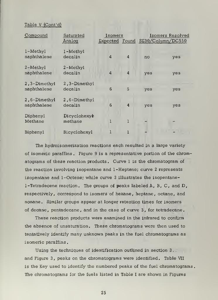
Table V (Cont'd)
Compound Saturated
1 -Methylnaphthalene
2-Methylnaphthalene
2, 3-Dimethylnaphthalene
2 , 6-Dimethylnaphthalene
DiphenylMethane
Biphenyl
Analog
1 -Methyldecalin
2-Methyldecalin
2,3-Dimethyldecalin
2, 6-Dimethyldecalin
Dicyclohexyfe
methane
Bicyclohexyl
Isomers Isomers ResolvedExpected Found SE30/Column/DC550
no
yes
yes
yes
yes
yes
yes
yes
The hydroisomerization reactions each resulted in a large variety
of isomeric paraffins. Figure 9 is a representative portion of the chrom-
atograms of these reaction products. Curve 1 is the chromatogram of
the reaction involving isopentane and 1-Heptene; curve 2 represents
isopentane and 1-Octene; while curve 3 illustrates the isopentane-
1-Tetradecene reaction. The groups of peaks labeled A, B, C, and D,
respectively , correspond to isomers of hexane, heptane, octane, and
nonane. Similar groups appear at longer retention times for isomers
of decane, pentadecane, and in the case of curve 3, for tetradecane.
These reaction products were examined in the infrared to confirm
the absence of unsaturation. These chromatograms were then used to
tentatively identify many unknown peaks in the fuel chromatograms as
isomeric paraffins.
Using the techniques of identification outlined in section 3, .
and Figure 3, peaks on the chromatograms were identified. Table VII
is the Key used to identify the numbered peaks of the fuel chromatograms
The chromatograms for the fuels listed in Table I are shown in Figures
25

(l-HEPTENE)
a
X
%(l-OCTENE)
B
\Wl rU y VyJ
4
V\I\_Aa,\l \u
1
3 6
|C
D
01
(7 - TEERR- B,1
1
DECENE)
\\rjlIjLj v3
ULCHROMAT06RAMS OF HYDROISOKRIZATION PRODUCTS
F/6URE9
26

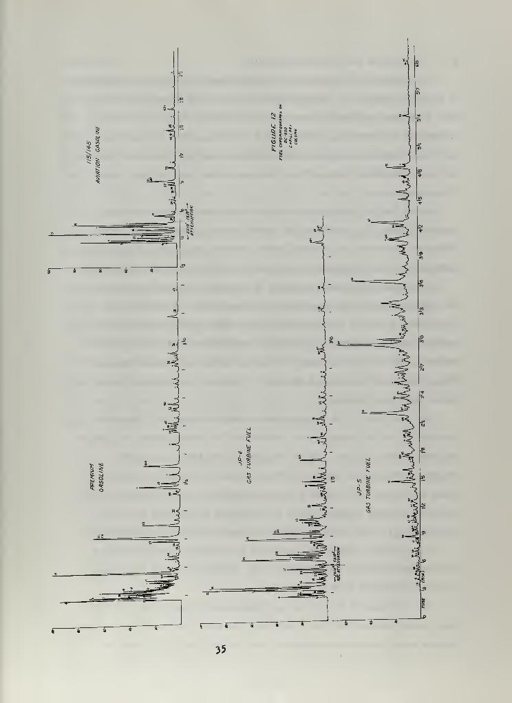
10-12. Figure 12 reproduces the chromatograms on the DC 550 column,
while figures 10 and 11 are reproductions of the chromatograms on the
SE 30 column. In addition to the numbered peaks, certain peaks have
been identified as aromatic, but otherwise unidentified. The aromatic
nature of such peaks is based on their reduction when the hydrogenated
fuel gas chromatogram is compared with that of the unreacted fuel.
These peaks are marked with a(+) on figures 10 - 12. Similarly, other
peaks have been tentatively identified as isomeric paraffins by com-
parison of the fuelJGC with the GC of the hydroisomerization reaction
products. These peaks are marked with a (°
) on figures 10 - 12.
The completeness of identification achieved with each fuel of the two
columns is summarized in Table VI.
Table VI
Summary of Component Identification
Fuel Peak
SE 30
:s
DC550Identified
SE 30 DC550Partially
SE 30
**Identified
DC 550
PremiumGasoline 55 83 32 37 4 28
Aviation
Gasoline 17 35 14 21 1 12
JP4 61 124 37 45 16 32
JP5 65 175 31 44 9 39
Canadian 88 200* 36 - 10 -
MarineDiesel 90 200* 35 16
(* Estimated) (**Either (+) or (ft))
In each case the DC 550 capillary column resolved the fuels into
many more components than were found on the SE 30 column. The
Canadian gas turbine fuel and marine diesel fuel were not analyzed on
the DC 550 column, since DC 550 does not have a sufficient temperature
27
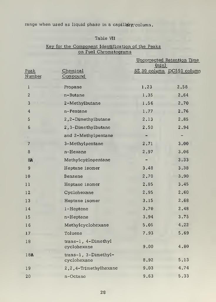
range when used as liquid phase in a capillabp/column.
Table VII
Key for the Component Identification of the Peakson Fuel Chromatograms
Uncorrected Retention Time(min)
Peak Chemical SE 30 column DC55 columnNumber Compound
1 Propane 1.23 2.58
2 n-Butane 1.35 2.64
3 2-Methylbutane 1.56 2.70
4 n-Pentane 1.77 2.76
5 2 , 2-Dimethylbutane 2.13 2.85
6 2 , 3-Dimethylbutane 2.50 2.94
and 2-Methylpentane - -
7 3-Methylpentane 2.71 3.00
8 n-Hexane 2.97 3.06
8A Methylcyclopentane - 3.33
9 Heptane isomer 3.48 3.38
10 Benzene 2.70 3.90
11 Heptane isomer 2.85 3.45
12 Cyclohexane 2.95 2.60
13 Heptane isomer 3.15 2.68
14 1-Heptene 3.70 2.48
15 n-Heptane 3.94 3.75
16 Methylcyclohexane 5.05 4.22
17 Toluene 7.93 5.69
18 trans-1, 4-Dimethylcyclohexane 9.00 4.80
18A trans-1 , 3-Dimethyl-cyclohexane 8.92 5.13
19 2,2, 4-Trimethylhexane 9.03 4.74
20 n-Octane 9.63 5.33
28

Table VII (Cont'd)
Peak ChemicalNumber Compound
21 trans-1 , 2-Dimethyl-cyclohexane
22 cis-1, 4-Dimethyl-cyclohexane
22A cis-1, 3-Dimethyl-cyclohexane
23 cis-1, 2-Dimethyl-cyclohexane
24 1 , 2 , 4-Trimethylcyclo-
hexane isomer
25 trans-1, 3, 5-Trimethyl-
cyclohexane
2 6 Ethylcyclohexane
27 Ethylbenzene
28 1/2, 4-Trimethylcyclo-
hexane isomer
29 1,2, 4-Trimethylcyclo-
hexane isomer
30 cis-1, 3, 5-Trimethyl-
cyclohexane
31 para-Xylene
31A meta-Xylene
32 1,2, 4-Trimethylcyclo-
hexane isomer
33 ortho-Xylene
34 n-nonane
35 Isopropylbenzene
(Cumene)
36 Cyclooctane
37 Isopropylcyclohexane
38 1/3, 5-Trimethylbenzene
(Mesitylene)
39 t-Butylbenzene
Uncorrected Retention Time(min)
SE 30 column DC 550 column
9.75 5.13
10.06 5.33
10.08 5.84
11.00 6.60
12.15 7.24
11.25 6.50
11.43 6.75
12.06 9.15
13.26 8.22
13.35 8.40
12.30 Z.35
12.45 9.49
12.45 9.49
13.45 8.55
13.45 10.96
14.04 8.78
14.77 12.50
15.03 11.10
15.10 10.50
16.57 15.50
17.58 17.00
29

Table VII (Cont'd) Uncorrected Retention Time(min)
Peak Chemical SE 30 column DC 550 columnNumber Compound
40 t-Butylcyclohexane 17.85 14.48
40A 1 -IAeptQ$yi\( 4>Me±hyi^jcyclohejxfan e - 13.64
41 n-Decane 18.03 14.56
42 Diethylcyclohexane isomer 18.18 14.86
42A 18.45 15.15
42B 18.67 15.42
42C 18.97 15.88
42D 19.27 16.30
42E 19.42 16.48
43 sec-Butylcyclohexane 19.27 17.20
43A 1,2, 4-Trimethylbenzene 19.35 17.37
44 meta-Diethylbenzene 19.65 21.35
45 para-Diethylbenzene 19.92 21.75
46 trans -1-t-Butyl, 4-Methyl-cyclohexane 19.95 18.00
47 ortho-Diethylbenzene 20.17 22^35
48 trans -Decahydronaphthalene 20.55 20.00
48A 1-Isopropyl, 4-Methylbenzene
49
(p-cymene)
cis-1-t-Butyl, 4-Methylcyclo-
19.29
hexane 20.65 19.30
50 para -t-Butyltoluene 21.33 24.15
51 n-Undecane 21.75 21.90
52 cis-Decahydronaphthalene 22.15 23.60
53 2 -Methyl decahydronaph-thalene isomer 22.62 23.97
53A ii n 23.47 25.65
53B ii ii 24.00 26.98
53C n ii 24.15 27.30
54 meta-and para-Diisopropyl-
benzene 23.40 28.45
30

Table VII (Cont'd) Uncorrected Retention Time
PeakNumber
55
56
57
57A
57B
57C
58
58A
59
59A
59B
59C
59C
60
61
61A
61B
61C
62
62A
62B
62C
62D
63
63A
64
ChemicalCompound
Tetrahydronaphthalene
isomers
ortho-Diisopropylbenzene
1 -Methyldecahydronaph-thalene isomer
Naphthalene
Triethylbenzene isomer
Diisopropylcyclohexaneisomer
n-Dodecane
2, 6-Dimethyldecahydro-
naphthalene isomer
2, 3-Dimethyldecahydro-naphthalene isomer
n-Tridecane
2-Methylnaphthalene
1 -Methylnaphthalene
(min)
$E 30 column DC 55 column
23. 82 30.66
24.03 30.25
23.46 25.11
24.37 27.70
24.60 28.20
24.99 28.84
24.59 33.45
- 33.67
23.94 26.40
24.15 26.74
24.67 27.48
25.20 27.82
25.74 29.25
25.15 29.11
24.57 27.75
25.50 29.41
25.86 30.30
26.67 32.85
26.10 30.37
26.43 30.90
27.69 31.80
28.35 32.70
29.11 34.74
28.32 36.00
28.32 40.69
28.68 42.07
n
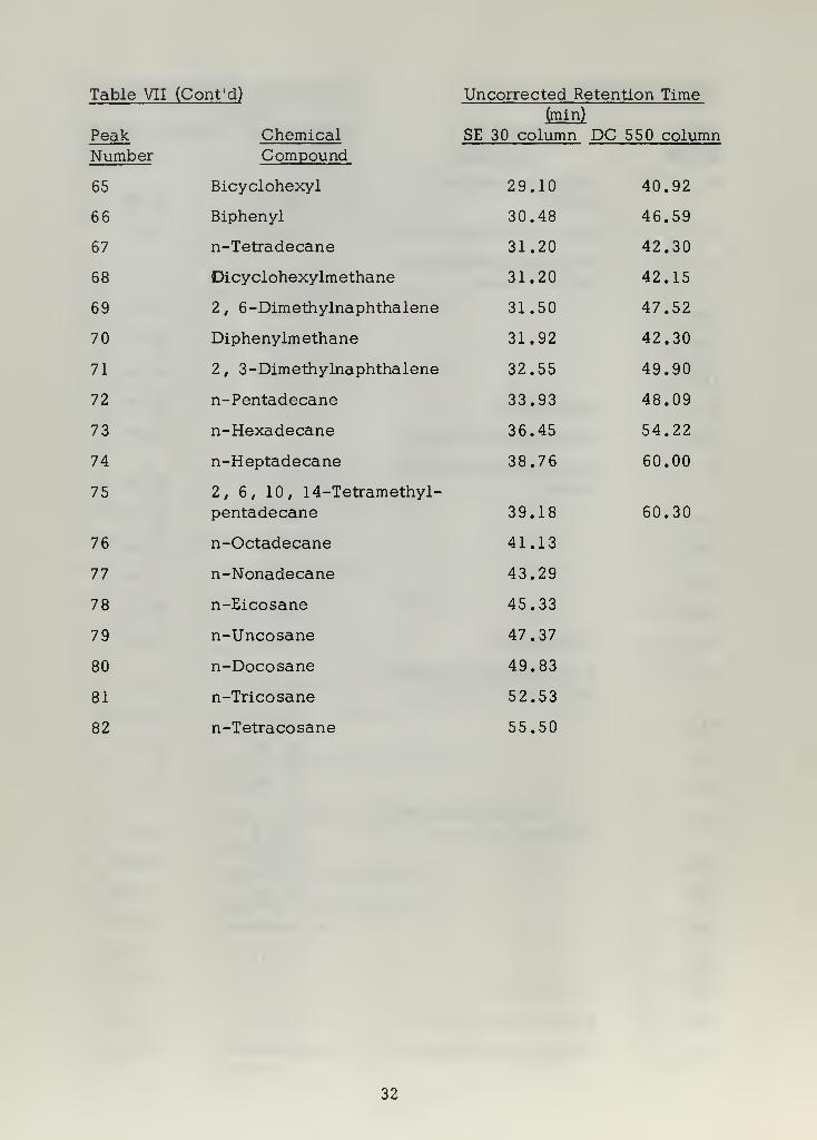
Table VII (Cont'd) Uncorrected Retention Time(min)
Peak Chemical SE 30 column DC 550 columnNumber Compound
65 Bicyclohexyl 29.10 40.92
66 Biphenyl 30.48 46.59
67 n-Tetradecane 31.20 42.30
68 Dicyclohexylmethane 31.20 42.15
69 2, 6-Dimethylnaphthalene 31.50 47.52
70 Diphenylmethane 31.92 42.30
71 2 , 3-Dimethylnaphthalene 32.55 49.90
72 n-Pentadecane 33.93 48.09
73 n-Hexadecane 36.45 54.22
74 n-Heptadecane 38.76 60.00
75 2, 6, 10, 14-Tetramethyl-
pentadecane 39.18 60.30
76 n-Octadecane 41.13
77 n-Nonadecane 43.29
78 n-Eicosane 45.33
79 n-Uncosane 47.37
80 n-Docosane 49.83
81 n-Tricosane 52.53
82 n-Tetracosane 55.50
32

-9
ID
4
*1
33• n

-9
-a
8
3V

5 . Conclusions and Acknowledgements
The overall gas chromatograms show clearly the relative complexity
of the fuels analyzed. Marine diesel fuel and the Canadian gas tur-
bine fuel are considerably more complex than the others. The chro-
matograms of these two, along with that of JP5 , show the typical
gaussian distribution of a straight boiling point cut from a distillation
column. The other fuels, JP4 and the gasolines, are blended, syn-
thetic mixtures
.
All of the gas turbine fuels investigated are high in aromatic
content (Table III). Additionally, each contains many of the highly
alkylated benzenes and naphthalenes, which contribute heavily to the
formation of carbonaceous residue due to their incomplete combustion.
No simple, economical method is presently available to reduce
the aromaticity of large quantities of these fuels. However, it is
considered practical to blend these fuels with paraffinic stock from
another source, in order to reduce the relative amounts of aromatics
present. Since the aromaticity of various crude oils varies consider-
ably, judicious choosing of the parent crude oil in preparing these fuels
would also be of benefit.
The analysis of the fuels is necessarily incomplete. The non-
availability of iso-paraffins as references for identification is a major
problem. This problem is most serious in the higher molecular
weights: decane and heavier. The multitude of isomers possible in
these molecules will render a complete analysis most difficult, since
the fuels studied contain traces of molecules as complex as tetra-
cosane (C24), with major quantities between decane and octadecane.
The following items are suggested as possible ways to improve
the analysis of these gas turbine fuels, as well as being applicable
to other analytical work of this type:
(a) Combine SE 30 and its high temperature capability with the
high resolution available in a capillary column. Such a SE 30 capillary
column would provide an excellent tool for the analysis of marine
3£

diesel fuel.
(b) Investigate the applicability of the methylene insertion re-
action for generating isomeric parrafin standards. Dvoretzky, Richard-
son , and Durrett [6 ] have shown that the statistical methylene in-
sertion reaction can be used for the small scale synthesis and elution-
time calibratiencoi many hitherto unavailable compounds. With each
hydrocarbon type reacted, the insertion of methylene into the carbon-
hydrogen bonds of the parent molecule allows the predictable synthesis
of isomeric next-higher homologs. Their work with n-heptane, various
isomeric hexanes, octanes, and nonanes should be capable of extention
to the heavier parrafins .
(c) Expand the work which has begun in hydrogenation of aromatics
and hydroisomerization at n-olefins . Of particular interest here might
be the isolation and identification of many geometric isomers of poly-
alkylated cyclohexanes and decahydronaphthalenes.
The writer wishes to express his appreciation for the assistance
and encouragement given him by Professor Glenn H. Spencer of the
U. S. Naval Postgraduate School. Appreciated also was the assistance
of Professor Charles F. Rowell who aided in the hydrogenation and
hydroisomerization portion of the investigation.
37

BIBLIOGRAPHY
1. Adkins, H. and Billica, H. R., The preparation of Raney nickelcatalysts and their use under conditions comparable with thosefor platinum and palladium catalysts . J. Am. Chem. Soc, 70 ,
695-698 (Feb. 1948).
2. Albert, D. K., Determination of C5 to C^ n-paraffins and hydro-
carbon types in gasoline by gas chromatography. Anal. Chem. , 35
,
1918-1921 (Nov. 1962).
3. Bert, J. A., Combustion characteristics of gas turbine fuels.
ATI 111 171 , Standard Oil Co. of Cal, California Research Corp.,Richmond. Progress Report No. 36 (July 1951).
4. Busch, A. M. , Correlation of laboratory smoke test with carbondeposition in turbojet combustors. NACA Research Memo . No.E9K04 (Feb. 1960).
5. Carroll, J. E. Jr, The flame ionization detector. Jarrell Ash GasPipe, 5 (Oct. 1963).
6. Dvoretzky, I., Richardson, D. B., and Durrett, L. R., Applications
of the methylene insertion reaction to componeat analysis of
hydrocarbons. Anal. Chem. , 35, 545-549 (April 1963).
7. Ettre, L. S., Condon, R. D., Kabot, F. J., and Cieplinski, E. W.Dual column-differential flame ionization detector system and its
application with both packed and open tubular columns. GasChromatography Applications , Perkin-Elmer Corp. App. No. GC-AP-003 (1963).
8. Golay, M. J. E. , Gas Chromatography, Academic Press, N. Y.
,
pp. 1-13, 1958, U. S. Patent No. 2,920,478.
9. Jonash, E. R., Barnett, H. C, and Strieker, E. G. , Investigation
of carbon deposition in an 1-16 jet-propulsion engine at static
sea -level conditions. NACA Research Memo. No. E6K01 (April
1947).
10. Kohler, H. L. and Miller, J. A. Gas turbine regenerator fouling
investigation progress report fiscal year 1965. U.S. Naval Post-
graduate School , TN No. 65T-2 (Aug. 1965).
11. McEwen, D. J., Temperature programmed capillary columns in
gas chromatography. Anal. Chem. ,35 , 1636-1640 (Oct. 1963).
12. Merritt, C. Jr., Walsh, J. T., Forss, D. A., and Swift, S. M.Wide range programmed temperature gas chromatography in the
separation of very complex mixtures. Anal. Chem . , 36 , 1502-1508
(July 1964).
38
13. Peterson, A. H. , Phillips, B. L. and Kelly, J. T. Hydroisomer-
ization of normal olefins under alkylation conditions . I&ECProduct Research and Development, 4 , 261-265 (Dec. 1965).
14. Schwartz, R. D. and Brasseaux, D. J. Resolution of complexhydrocarbon mixtures by capillary column gas liquid chromato-graphy. Anal. Chem., 35, 1374-1382 (Sept. 1963).
15. Wear, J. D. and Jonash, E. R. Carbon deposition of 19 fuels
in an annular turbojet combustor. NACA Research Memo . No.E8K22 (Feb. 1949).
33

INITIAL DISTRIBUTION LIST
No. Copies
1 . Defense Documentation CenterCameron Station
Alexandria, Virginia 22314 20
2 . Library
U.S. Naval Postgraduate SchoolMonterey, California 93940 2
3. Chief, Bureau of Ships, Code 645
Department of the NavyWashington, D. C. 1
4. Prof. Glenn H. SpencerDepartment of Material Science and ChemistryU.S. Naval Postgraduate School
Monterey, California 93940 5
5 . LCDR Robert C . Beers , USN32 West State St.
Media, Pennsylvania 2
6. Prof. Henry L. Kohler
Department of Aeronautics
U. S. Naval Postgraduate SchoolMonterey, California 93940 2
7. Prof. James A. Miller
Department of Aeronautics
U.S. Naval Postgraduate School
Monterey, California 93940 1
8. Prof. Charles F. Rowell
Department of Material Science and Chemistry
U. S. Naval Postgraduate School
Monterey, California 93940 1
4D

UnclassifiedSecurity Classification
DOCUMENT CONTROL DATA - R&D(Security claaaitication ot titla, body at mbutrmct and indexing annotation must be ante red wfian thai ovarall report is claastttad)
1. ORIGINATING ACTIVITY (Corpotata author)
U. S. Naval Postgraduate School
Monterey, California 93940
2a REPORT SECURITY C L A3SIFICA TION
Unclassified26 CROUP
3. REPORT TITLE
The Application of Gas Chromatography to the Analysis of Certain HydrocarbonFuels
4. DESCRIPTIVE NOTES (Type ©/ report mnd lnctuatva datea)
Masthers Thesis in Chemistry, May 19665. AUTHORfSJ (Lmot name. Hrmt name, tnittml)
Beers, Robert Cleve Lieutenant Commander U.S. Navy
6. REPORT DATE
May 1966
7a. TOTAL NO. OF PACES
39
7b. NO- OF REPS
15
8a. CONTRACT OR ORANT NO.
b. PROJECT NO.
9« ORIGINATOR'S REPORT NUMBER^
9b. OTHER REPORT HO(S) (A ny othar numbara that may ba aaalgnadthia import)
d.
This document has been apcoved for publiorelease and sale; its disu xoution is unlimited.
10. AVAILABILITY/LIMITATION NOTICES
t6L'jkl
11. SUPPLEMENTARY NOTES 12- SPONSORING MILITARY ACTIVITY
BuShips (Code 645)
13. ABSTRACT
As part of an investigation of gas turbine regenerator fouling being
conducted at the U.S. Naval Postgraduate School gas chromatography wasused to compare and analyze certain hydrocarbon fuels. Because of the
known relationship between fuel aromaticity and exhaust system fouling in
gas turbine engines, particular emphasis was directed toward determination
of the aromaticity of the fuels and of the particular aromatic compounds present
Fuels investigated included premium grade auto gasoline, aviation gasoline,
several gas turbine fuels, and marine diesel fuel. Derivatives of cyclohexane
and decahudronaphthalene were synthesized by hydrogenation of benzene and
naphthalene derivatives with Raney nickel catalyst. Numerous branched-
chain paraffins were synthesized by hydroisomerization of n-olefins under
alkylation conditions. These synthetic products were used as standards in
the identification of components of the fuels. The fuels investigated were
found to contain from 35 to over 200 components. Component identification
was from 30 to 60% complete.
DD FORM1 JAN 64 1473 Unclassified
41 Security Classification
UnclassifiedSecurity Classification
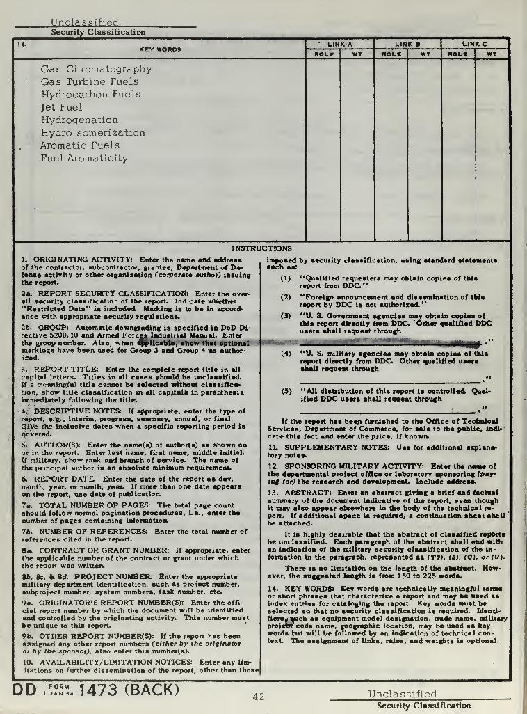
14-KEY WORDS
LINK A
ROLELINK
HOLE WTLINK C
ROLI WT
Gas ChromatographyGas Turbine Fuels
Hydrocarbon Fuels
Jet Fuel
HydrogenationHydroisomerization
Aromatic Fuels
Fuel Aromaticity
INSTRUCTIONS
1. ORIGINATING ACTIVITY: Enter the name and addressof the contractor, subcontractor, grantee, Department of De-fense activity or other organization (corporate author) issuingthe report.
2a. REPORT SECUFSTY CLASSIFICATION: Enter the over-all security classification of the report. Indicate whether"Restricted Data" is included. Marking is to be in accord-ance with appropriate security regulations.
2b. GROUP: Automatic downgrading is specified in DoD Di-rective 5200. 10 and Armed Forces Industrial Manual. Enterthe group number. Also, when applicable, show that optionalmarkings have been used for Group 3 and Group 4 as author-ized.
& REPORT TITLE: Enter the complete report title in all
capital letters. Titles in all cases should be unclassified.
If a meaningful title cannot be selected without classifica-tion, show title classification in all capitals in parenthesisimmediately following the title.
4. DESCRIPTIVE NOTES: If appropriate, enter the type of
report, e.g., interim, progress, summary, annual, or final.
Give the inclusive dates when a specific reporting period ia
Covered.
5. AUTHOR(S): Enter the name<s) of author{a) as shown onor in the report. Enter last name, first name, middle initial.
If military, show rank and branch of service. The name of
the principal author is an absolute minimum requirement.
6. REPORT DATE: Enter the dste of the report as day,month, year; or month, year. If more than one date appearson the report, use date of publication.
7a. TOTAL NUMBER OF PAGES: The total page countshould follow normal pagination procedures, Le. , enter thenumber of pages containing information.
7b. NUMBER OF REFERENCES: Enter the total number of
references cited in the report.
8a. CONTRACT OR GRANT NUMBER: If appropriate, enter
the applicable number of the contract or grant under whichthe report was written.
8b, 8c, & 8d. PROJECT NUMBER: Enter the appropriatemilitary department identification, such as project number,subproject number, system numbers, task number, etc
9a. ORIGINATOR'S REPORT NUMBER(S): Enter the offi-
cial report number by which the document will be identified
and controlled by the originating activity. This number mustbe unique to this report.
9b. OTHER REPORT NUMBERfS): If the report has beenassigned any other report numbers (either by the originatoror by the sponsor), also enter this number(s).
10. AVAILABILITY/LIMITATION NOTICES: Enter any lim-
itations on further dissemination of the report, other than those
imposed by security classification, using standard statementssuch as:
(1) "Qualified requesters may obtain copies of thisreport from DDC"
(2) "Foreign announcement and dissemination of this
report by DDC is not authorized.
"
(3) "U. S. Government agencies may obtain copies ofthis report directly from DDC. Other qualified DDCusers shall request through
Use for additional explane-
(4) "U. S. military agencies may obtain copies of this
report directly from DDC Other qualified usersshall request through
(5) "All distribution of this report is controlled. Qual-ified DDC users shall request through
If the report has beep furnished to the Office of TechnicalServices, Department of Commerce, for sale to the public, indi-
cate this feet and enter the price, if known.
1L SUPPLEMENTARY NOTES:tory notes.
12. SPONSORING MILITARY ACTIVITY: Enter the name ofthe departmental project office or laboratory sponsoring (pay-ing tor) the resesrch and development Include address.
13- ABSTRACT: Enter an abstract giving a brief and factual
summary of the document indicative of the report, even thoughit may also appear elsewhere in the body of the technical re-
port. If additional apace ia required, a continuation sheet shallbe attached.
It ia highly desirable that the abstract of classified reportsbe unclassified. Each paragraph of the abstract shall end withan indication of the military security classification of the in-
formation in the paragraph, represented as (TS), (S). (C), or (U)
There ia no limitation on the length of the abstract. How-ever, the suggested length is from 150 to 225 words.
14. KEY WORDS: Key words are technically meaningful termsor short phrases that characterize a report and may be used aaindex entries for cataloging the report. Key words must beselected so diet no security classification is required. Identi-
fiers- sjuch ss equipment model designation, trade name, militaryprojerSY code name, geographic location, may be uaed aa keywords but will be followed by an indication of technical con-text. The assignment of links, r«Jes, and weights ia optional
0D FORM1 JAN 84 1473 (BACK) 42 Unclassified
Security Classification


thesB351
The application of gas chromatography to
3 2768 002 12946 2
DUDLEY KNOX LIBRARY
M ;
-.-ii-'';i
:'•<'•A-'-'
:.;.'. -..(•.7,:;.:j::,;.:;'-.»..'::