the anti-earthquake safety evaluation of lock chamber
TRANSCRIPT

The Anti-earthquake Safety Evaluation of Lock Chamber Based on Finite Element Method
Lijia Ma1, a , Dandan Li2, b *, Qian Cai2, c 1 Guangdong Technical College of Water Resources and Electric Engineering, Guangdong, China
2 Nanjing Hydraulic Research Institute, Jiangsu, China [email protected]
[email protected] [email protected]
Keywords: Lock chanmber, anti-earthquake safety, finite element Abstract. The sluice is located in the place where the basic seismic intensity is degree 8. According to anti-earthquake safety calculation of lock chamber based on finite element method, the result shows that the displacement of the lock chamber is within safe levels and that the strength of sluice satisfies standardized requirements. However, lock chamber stability fails to meet the requirements. Therefore, demolition and reconstruction are recommended.
Introduction The design flow of the sluice is 500m3/s and the check flow is 1000 m3/s, which denotes a stage- II
project. With the reinforced concrete structure, the sluice has seven holes each of which is 9.2m in clear width and 4.0m in clear height. The sluice is located in the place where the basic seismic intensity is degree 8 and the corresponding seismic fortification intensity is also degree 8. Notwithstanding, seismic fortification was not taken into consideration in the initial construction of the project, and thus we need to make the seismic safety evaluation of the current bottom slab [1,2].
Calculation method and calculation model Based on the field test of geological drilling and analysis of observation data in this seismic safety
evaluation, the dynamic response of the sluice to bedrock can be confirmed including the displacement, velocity, and acceleration in every point of the sluice and the seismic motion of the lock chamber through seismic dynamic response simulation calculation [3,4]. The three-dimensional finite element model can also be established according to the calculation results and the analysis of overall seismic stability of lock chambe.
The calculating range of the model is 1.5 times of the gate width upstream, 1.5 times of the gate width downstream, 2 times of the gate height downward to the bedrock and about 1 time of the gate width along the left and right bank. In the computational domain, apply longitudinal linkage constraint upstream and downstream, transverse linkage constraint at the left and right bank, and complete displacement constraint at the bottom. The sluice uses w-w yield criterion and the bedrock is assumed to be isotropic material.
Use eight-node isoparametric element to do mesh dissection and the three-dimensional finite element model is shown in Fig. 1
5th International Conference on Civil Engineering and Transportation (ICCET 2015)
© 2015. The authors - Published by Atlantis Press 77

Figure 1 The finite element model of lock chamber
Parameter calculation The combination conditions of seismic safety check on sluice structures are: error-free running
period (in the reservoir level, the upper level is 23.50m and the downstream level is 18.50m), and M8.0 earthquake (dynamic peak acceleration is 0.30g, and the period is 0.35s). Response spectrum method of dynamic analysis uses the decomposition reaction spectral method for the analysis, and select ten modals of the whole structure through modal analysis to get the modes and frequency of structural self-vibration [5]. The design response spectrum provided by Specifications for Seismic Design of Hydraulic Structures is shown in Figure 2. Response spectrum analysis results of modes can be obtained, according to mode frequencies and the value of the reaction spectrum selected from design response spectrum diagram with the modal expansion of the ten modes.
Figure 2 The diagram of design response spectrum
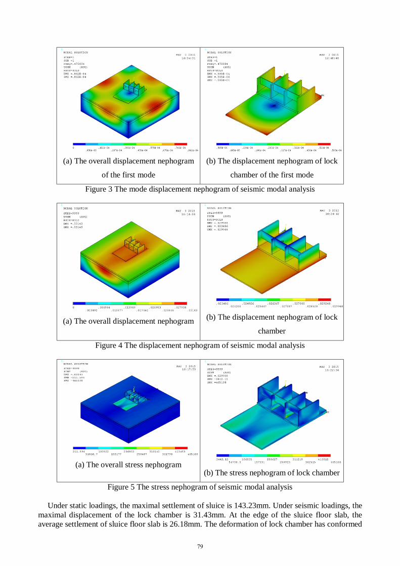
Finite element analysis results The mode displacement nephogram of seismic modal analysis is shown in Figure 3 and the
displacement nephogram of seismic modal analysis is shown in Figure 4. The stress nephogram of seismic modal analysis is shown in Figure 5. In the nephogram, pressure stress is positive and tensile stress is negative with Pa as the unit of the stress. As for the longitudinal displacement, the upstream is deemed as positive, and the downstream is negative. The transverse displacement heading towards the left bank is positive, the right bank negative. The vertical displacement above is deemed as positive, downward negative with m as the unit of displacement.
78
(a) The overall displacement nephogram
of the first mode
(b) The displacement nephogram of lock
chamber of the first mode
Figure 3 The mode displacement nephogram of seismic modal analysis
(a) The overall displacement nephogram (b) The displacement nephogram of lock
chamber
Figure 4 The displacement nephogram of seismic modal analysis
(a) The overall stress nephogram (b) The stress nephogram of lock chamber
Figure 5 The stress nephogram of seismic modal analysis
Under static loadings, the maximal settlement of sluice is 143.23mm. Under seismic loadings, the maximal displacement of the lock chamber is 31.43mm. At the edge of the sluice floor slab, the average settlement of sluice floor slab is 26.18mm. The deformation of lock chamber has conformed
79

to the rules of seismic action and has met the requirements of safe operation and regulations. The displacement of pocket floor also satisfies safe operation requirements.
C20 concrete is used in sluice piers and C25 concrete for the sluice floor slab. The reinforcement arrangement shall be in accordance with the structural requirements. Under seismic loadings, the maximal compressive stress of the lock chamber is 0.465MPa. At the junction of the bottom of the sluice piers upstream and the gate floor, the maximal compressive stress is less than allowable compressive stress of concrete. Also, the maximal tensile stress is -76.76kPa, which is less than allowable tensile stress of concrete in the middle of the chest and the gate floor. Therefore, the intensity of sluice meets standardized requirements.
Conclusion According to the seismic safety check results of the lock chamber, the anti-slide stability and
safety coefficients of lock chamber with antishider and without antishider are both less than the criterion value. The seismic safety of the lock chamber does not meet the standardized requirements. In view of the existence of liquefaction soil layer at the sluice foundation and the unqualified calculation results of lock chamber stability, demolition and reconstruction is suggested to start.
Acknowledgements This work was financially supported by the Fundamental Research Funds of Nanjing Hydraulic Research Institute (Y714005 and Y715003).
References [1] Xinyong Xu, Yingbin Kang, Quansheng Luo, “Study on Anti-Seismic Safety Assessment of Huanhe River Landscape Sluice Engineering ”, Yellow River, 34 (2012): 147-148.
[2] Yun Wang, “Simulated Analysis of Sluice Considering Earthquake Effect”, Hebei University of Engineering (2011).
[3] Jinping Ou, Ditao Niu, “Parameters and Structure Effect of Random Model about Earthquake Ground Motion”, J. Harbin Archit. & Civ. Engc Inst, 10 (1990):70-76.
[4] Qing Wang, Defa Guo, “Finite Element Analysis of the Whole Structure of Sluice Foundation”, China Water Transport, 9 (2009): 149-151.
[5] Haitao Cui, Juan Li, Jun Zeng, “Finite Element Analysis and Stress Reinforcement for Inlet Chamber of Diversion Tunnel”, Journal of Water Resources and Architectural Engineering, 9 (2011):146-149.
80