the altitude wind tunnel (a wt)-a unique facility for ... · iiuiii\i \iu 11\1 uiii ui\i iiui iiu\...
TRANSCRIPT

-.
NASA Technical Memorandum 86921 AIAA-85-0314
NASA-TM-86921
J9fo(JtJt) 116-g
The Altitude Wind Tunnel (A WT)-A Unique Facility for Propulsion System and Adverse Weather Testing
Roger Chamberlin Lewis Research Center Cleveland, Ohio
Prepared for the Twenty-third Aerospace Sciences Meeting
JUN -~ '.l;-i ... -.. •
LrlNGlL • '~l _.
UriR'-RY, I'IA:' \
HArM-TON, VIRGiNI \
sponsored by the American Institute of Aeronautics and Astronautics Reno, Nevada, January 14-17, 1985
NI\5I\ IIUIII\I \IU 11\1 UIII UI\I IIUI IIU\ IIII 1\\1
NFOO1l3 --
https://ntrs.nasa.gov/search.jsp?R=19850009758 2019-02-15T05:59:07+00:00Z

THE ALTITUDE WIND TUNNEL (AWT) - A UNIQUE FACILITY FOR PROPULSION SYSTEM AND ADVERSE WEATHER TESTING
Roger Chamberlln Natlonal Aeronautlcs and Space Admlnlstratlon
Lewls Research Center ~ Cleveland, OhlO 44135
Summary
A need has arlsen for a new wlnd tunnel faclllty wlth unlque capabllltles for testlng propulslon systems and for conductlng research In adverse weather condltlons. New propulslon system concepts, new alrcraft conflguratlons wlth an unprecedented degree of propulslon system/alrcraft lntegratlon, and requlrements for alrcraft operatlon In adverse weather dl.Gtate the need for a new test faclllty. Requlred capabllltles lnclude Slmulatlon of both altltude pressure and temperature, large Slze, full subsonlc speed range, propulslon system operatlon, and weather slmulatlon (l.e., lClng, heavy raln). A cost effectlve rehabllltatlon of the NASA LeW1S Research Center's Altltude Wlnd Tunnel (AWT) wlll provlde a faclllty wlth all these capabllltles.
Introductlon
Future new alrcraft and propulslon systems wlll requlre wlnd tunnel test facllltles wlth unlque capabllltles that currently are not avallable In thlS country.l,2 Future alrcraft of all types, C1Vll and mllltary, wlll place lncreased emphasls on propulslon system lntegratlon, both the propulSlon system wlth the alrframe, as well as between propulslon system components. Future emphasls wlll also be placed on lncreased alrcraft operatlonal capabllltles, WhlCh means operatlng In adverse weather condltlons. These factors wlll requlre wlnd tunnel facllltles that are large, slmulate true altltude condltlons (lncludlng temperature), permlt the operatlon of a propulslon system, and can slmulate adverse weather condltlons. There lS no large scale wlnd tunnel In the Unlted States or the free world that provldes these capabllltles. The Altltude Wlnd ~unnel (AWT), located at the NASA Lewls Research Center In Cleveland, OhlO, could be modlfled In a cost effectlve manner to provlde all of these necessary capabllltles.
A blue-rlbbon commlttee was formed In 1982 to reVlew the natlonal aeronautlcs research and technology pOllCy.3 The flndlngs of the commlttee are summarlzed In Flg. 1. Slgnlflcant galns In • alrcraft and alrcraft propulslon system performance are yet to be made. The study concluded that numerous opportunltles eXlst for maklng dramatlc leaps In technology. Indeed, all currently operatlonal mllltary and C1Vll alrcraft could be technolog1cally superseded by the end of the century. Whlle advances are posslble, achlevlng them wlll not be easy and advanced fllght vehlcles wlll requlre a conslderable degree of propulslon system/ dlrframe lntegratlon. Integratlon of aerodynamlcs, rnaterlals and structures, and propulslon wlll play an lncreaslngly lmportant role In the development of future mllltary and C1Vll alrcraft. These new hlghly lntegrated systems wlll requlre a new type of test faclllty.
Operatlon of alrcraft In adverse weather (such as heavy raln, lClng condltlons, etc.) lS a hazardous sltuatlon for both mllltary and C1Vll alrcraft.
The only wlnd tunnel In thlS country for conductlng lClng research lS the IClng Research Tunnel at the Lewls Research Center. ThlS faclllty, whlle heavlly used and a very valuable tool, lS small and has only low-speed capabllltles. ThlS tunnel does not permlt englne operatlon nor slmulate altltude pressure.
Future Aeronautlcal Systems
Some of the new alrcraft systems that are expected to evolve In the future are llsted In Flg. 2. These new alrcraft systems wlll lncorporate new or modlfled types of propulslon systems, somewhat dlfferent than those currently In serVlce. Future systems wlll lncorporate propulslon concepts WhlCh wlll be more efflclent, and WhlCh wlll not only develop thrust, but In some appllcatlons wlll also produce 11ft. In other appllcatlons the propulslon system wlll be used as an ald for alrcraft stablllty and control. These new conflguratlons wlll requlre alrframe and propulslon system lntegratlon to a degree of SOphlstlcatlon far beyond any current systems.
There lS an lncreaslng need, for productlvlty, mlSSlon effectlveness, and survlvablllty, to operate at wlll In all types of weather condltlons (lclng, snow, heavy raln). Mllltary operatlons are, of course, not llmlted to areas or seasons of favorable cllmatlc condltlons. C1Vll alrcraft must operate year round and In all parts of the world, and therefore frequently encounter adverse weather condltlons. Current transport alrcraft have some lce protectlve devlces, but future alrcraft wlll lncorporate dlfferent features such as zero bleed englnes and composlte materlals etc., that wlll not permlt the use of the klnds of protectlve systems used on eXlstlng alrcraft. New protectlon systems wlll have to be developed and thlS can only be done wlth a thorough understandlng of the entlre alrcraft/propulslon system when operatlng under reallstlc envlronmental condltlons.
In recent years the prlce of alrcraft fuel has stablllzed. However, It stlll represents a Slzeable portlon of the alrcraft dlrect operatlng cost, approxlmately 50 percent, and It 15 probable that fuel prlces wlll rlse agaln at sometlme In the future. Therefore energy efflclency lS stlll extremely lmportant to the alrcraft/alrllne lndustry. One of the propulslon system concepts currently belng evaluated for slgnlflcantly reduclng transport alrcraft fuel consumptlon 15 the hlghspeed turboprop (Flg. 3). Through approprlate technologlcal advancements, thlS concept has the potentlal to reduce alrcraft fuel consumptlon by 20 to 30 percent compared to the best state-of-the-art turbofan englne. Fuel savlngs of thlS magnltude would slgnlflcantly lmprove alrllne carrler profltablllty and posslbly open up large new world markets for short/medlum range alrcraft. The lntegratlon of thlS propulslon concept wlth the alrframe lS very dlfferent from current turbofan lnstallatlons. MaJor advancements In understandlng

the phenomena controll1ng the successful 1ntegratlon of th1S concept wlll be needed 1n order to real1ze these slgn1f1cant performance 1mprovements.
New h1ghly surv1vable m1l1tary a1rcraft concepts (F1g. 4) w1ll present a n~ and complex set of potent1al problems w1th regard to the 1mpact of 1nstallat1on effects on the performance and operab1l1ty of the propuls1on systems. For these veh1-cles, less V1S1b1l1ty to radar detect10n 1S sought by sh1eld1ng or mask1ng the "hard parts" of an enq1ne such as the rotat1ng mach1nery, the "hot parts· such as the exhaust nozzles and turb1nes, and the hot exhaust gases. Maneuverab1l1ty 1S another 1mportant feature of many of these a1rcraft. H1gh maneuverab111ty 1S accompl1shed w1th exhaust nozzles Wh1Ch can be used to deflect the hot exhaust Jet to a1d t~~erodynam1c control surfaces. The des1gn 1ngenu1ty needed to ach1eve th1S sh1eld1ng and maneuverab111ty generally results 1n complex and tortuous eng1ne a1r 1nlet and eXlt systems such as mult1turn a1r 1ntakes and two-dlmenslonal h1gh aspect rat10 nozzles. These co-plex and tortuous a1r lntake systems w1l1 tend to accumulate lce mak1ng all weather operat10n dlfflcult A total 1ntegrated systems approach to the analysls and evaluat10n of th1S class of a1r~raft 1S needed 1n order to opt1m1ze the overall ~erformance.
The potentlal for develoP1ng h1gh performance JI.d ,afe vert1cal/short take-off and land1ng a1rcraft (V/STOL) (F1g. 5) 1S be1ng explored uS1ng operatIng exper1mental veh1cles and conceptual deSlqn studles. The technolog1es needed to cap1-tallze on the operat1ng flex1b111ty advantages assoclated w1th th1S type of a1rcraft are be1ng explored for lntermed1ate subsonlc speeds uS1ng the 'l~SA/Army tllt rotor exper1mental veh1cle and for hlqh subsonlC and supersonlc speeds uSlng des1gn concepts emploY1ng deflected Jets and eJector 11ft prlnClples. The need to accurately understand the effect of the lnstallat10n on the propuls10n system ~hlCh provldes the vert1cal 11ft power as well as the forward fllght thrust 1S cr1t1cal to the success of these a1rcraft.
New concepts for rotorcraft (F1g. 6) are be1ng ger.erated wlth the emphaS1s on ach1ev1ng much hlgher operatlonal speeds (Mo ~ 0.8). State-ofthe-art rotorcraft are 11m1ted to low subson1c fllght speeds due to llm1tat1ons lmposed by the large rotat1ng set of blades used dur1ng both vertlcal and horlzontal fl1ght. As forward fl1ght speed lncreases the 11ft to drag eff1c1ency of current technology rotors 1S slgn1f1cantly degraded and structural concerns become ser10US. New approaches, such as the X-w1ng concept where1n the rotor becomes a stat10nary llftlng dev1ce and the advanclng blade concept where1n two counter rotatlng rotors are used, have the potent1al for allev1-atlng the current forward fl1ght speed llm1tat10ns of rotorcraft. These concepts have the potent1al for expandlng the forward fl1ght envelope of future rotorcraft to the m1d to h1gh subson1c speed range. Propuls1on/alrframe 1ntegrat10n technology challenges, not present 1n state-of-the-art rotorcraft, must be addressed w1th these new systems. The need to successfully accompl1sh the trans1t10n between shaft power operat10n and Jet thrust 1S cr1t1cal to the future success of these veh1cles as 1S the need to deslgn h1gh performance eng1ne 1ntake and exhaust systems for efflclent h1gh-speed forward
2
fl1ght. These technology challen~es must be studled and resolved through systems lntegrat10n analys1s and exper1ment.
Propuls10n System Integrat10n Fac111ty Requ1rements
Many future a1rcraft concepts have propulslon systems h1ghly 1ntegrated w1th the a1rframe (l.e., where the a1rframe/1nstallat1on has a pronounced effect on the performance of the propulslon system), and 1n some cases 1nvolve new propulslon system concepts such as the h1gh-speed turboprop. The propuls1on un1t may be burled w1th1n the a1rframe or closely coupled w1th lt and be performlng funct10ns 1n add1t10n to prov1d1ng thrust, such as prov1d1ng a1rcraft stab1l1ty and control. Tests of the propuls1on system w111 requ1re port10ns of the alrframe to correctly slmulate the 1nstalled enV1-ronment (F1g. 7). Tests 1n eng1ne test tanks are not suff1c1ent for these h1ghly complex 1ntegrated systems. These new systems requ1re a w1nd tunnel test conf1gurat10n Wh1Ch can prov1de the actual 1nternal flow fleld as well as the external flow f1eld. For example, the rotat1ng propeller of the turboprop system 1S closely coupled to the external flow f1eld of the a1rcraft. The external flow must be slmulated 1n order to 1nvest1gate the operatlon of the total system. ThlS d1ffers from current turbofan or turboJet englnes Wh1Ch have 1nlets to condltlon the flow before It reaches the eng1ne.
Because the propuls10n system and a port10n of the a1rframe as well must be tested concurrently, requlres e1ther a large Slze wlnd tunnel or work1ng at subscale. Subscale test1ng of system performance/1nteract10n 1S not adequate because of the problems 1n Slmultaneously scal1ng aerodynamlc, structural, and mechanlcal behav1or. Also the slmulat10n of adverse weather does not scale well (d1scussed 1n more deta11 1n the next sect10n). Therefore, a requ1rement for th1S new fac1l1ty 1S that 1t be a w1nd tunnel conf1guratlon and large enough to perm1t full or large scale test art1cles
A tYP1cal subson1C fl1ght prof1le 1S shown 1n F1g. 8. The dashed 11ne represents the operat1ng 11ne of a tYP1cal sea level wlnd tunnel. As can be seen th1S type of fac111ty can only slmulate a very small port1on of the fl1ght envelope. In a sea level fac111ty the tests performed at almost all speeds are at an amb1ent pressure slgn1flcantly h1gher than would be encountered 1n actual fl1ght. The h1gher pressures result 1n slgnlf1cantly greater loads on the eng1ne components. In an atmospherlc tunnel the a1r dens1ty can be as much as three t1mes h1gher than at true alt1tude, WhlCh can cause slgn1f1cant changes 1n the aerodynam1c performance of propellers, fans, compressors, etc. The h1gher a1r denslty also results 1n unreallstlc loadlng patterns on these components Wh1Ch requ1res the test hardware to have a d1fferent structural character1st1c or poss1bly a d1fferent mechan1cal des1gn, thus mak1ng the test unrepresentat1ve. Therefore, another fac1l1ty requ1rement 1S slmulat10n of the correct alt1tude pressure.
In actual fl1ght, not only does the amb1ent pressure drop w1th 1ncreas1ng altltude, but so does the temperature. Most of the eX1stlng w1nd tunnels are not refr1gerated and therefore operate a temperatures slgn1f1cantly h1gher than 1n actual fl1ght. F1gure 9 lllustrates th1S d1fference and the lmpact caused by thlS dlfference. A tYPlcal

unrefrlgerated wInd tunnel wIll generally op~rate at stagnatlon temperatures ln excess of 100 F hotter than true altltude temperatures. In order to achleve aerodynamlc slmllarlty when testlng a propulsIon system the corrected speed N/~ must be the same as would occur ln fllght. If the aIr temperature T, durlng the test lS ~o hIgh, then the rotatIonal speed N must be Increased correspondlng1¥. A temperature dIfference between 110 and 120 F, as used In thlS exam~le, requIres that the engIne be oversped by 10 to 12 percent. Overspeedlng the engIne has several effects whIch can lImIt or InvalIdate the results of the test. An overspeed of thIs amount would Increase the centrIfugal forces In the rotor, fan, or propeller blades by 25 percent. ThIs may requIre uSIng a dlfferent blade constructIon technIque or added strength bUIlt Into the blades. In eIther case, the blades would have a dIfferent str~etural response than the actual blade desIgn. Also the Increased rotatIonal speed wIll cause the blades to deflect or untwIst dlfferent1y than deslgned and therefore wlll result In a dIfferent shape. Both the Increased centrIfugal loads and the blade untwIst dIfferences can sIgnIfIcantly change the flutter characterIstIcs. In addItIon to the changes In the flutter characterIstICS of the blades the hIgher rotatIonal speed changes the forces from the engIne. The-engIne would be runnIng at hIgher than desIgn speeds and therefore operatIng wIth a dIfferent vlbratlonal sIgnature than the desIgn condItIon. All of these factors lead to a test sItuatIon that IS mechanIcally very dIfferent from actual flIght. Therefore, another test facIlIty requIrement IS that J~blent temperature be correctly sImulated.
The necessary facIlIty capabIlItIes for conductIng propulsIon system IntegratIon research are surmarlzed In FIg. 10. Currently there IS no facIlIty 1n eXIstence that can provIde all these capabIlItIes
Adverse Weather OperatIon
To fully exploIt the potentIal of the future energy effIcIent, hIgh performance, survIvable, and operatIonally fleXIble aIrcraft requIres that they be capable of successfully operatIng In all weather condItIons (FIg. 11). ContInuIng pressure to expand flIght envelopes, geographIc routes, and flIght frequency, IndIcates that the effects of weather phenomena such as ICIng, snow, and heavy raIn must contInue to be explored and thIS can only be done under realIstIc envIronmental condItIons. Successfully achIevIng all weather operatIonal capabIlIty In future hIghly survIvable mIlItary alr- • craft, and In current and future rotorcraft requIres a more thorough understandIng of the potentIal adverse effects of weather on these concepts. Today these condItIons can only be found V1a costly, t1me consum1ng and rIsky flIght test1ng.
Current large transport a1rcraft have some protectIon systems wh1ch are effectIve. However, future changes to propulsIon systems and to the a1rframe wIll no longer perm1t the use of these eX1stlng systems and new ones w111 have to be developed. In order to perform adverse weather research, specla11zed facl11ty capabl11tles are requ1red. ICIng research w111 be developed as an IllustratIve example to determ1ne the type of facl11ty capab111tles needed for adverse weather testIng
3
All parts of an aIrcraft are subJect to lClng, however, lce accretlon on some components (l.e., propulsIon system, wlng) lS very crltlcal to the alrcraft operatlon. Some of these components are lIsted In FIg. 12. Inlets and carburetors, of course, are crItIcal to the operat10n of the engIne and have been shown to be very effIcIent Ice collectors. Fans and propellers have sharp leadIng edges and can collect Ice easIly, wh1ch could d1srupt the flow over the blade and cause losses In thrust. New advanced aIrfoIls also are thIn and can accumulate Ice on the 1ead1ng edge and lIttle IS known about the aerodynamIc penaltIes of these new shapes as Ice accumulates. The same IS true for rotorcraft.
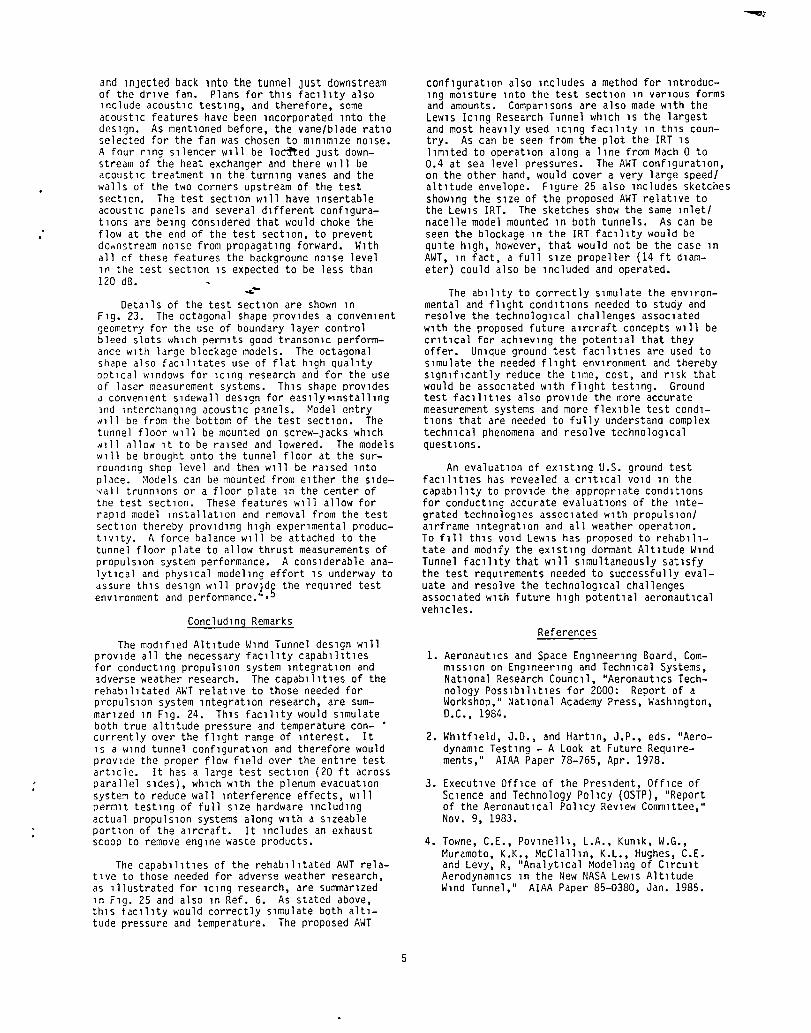
As mentIoned prevIously, new propulsIon systems and aIrcraft desIgns wIll not always permIt the use of Ice protectIon systems of the type used on current transport aIrcraft. FIgure 13 lIsts some of the new developments that wIll Impact the operatIon of and the klnd of lce protectlon systems that can be used. The need for Improved fuel effIcIency IS changIng current engIne desIgns and one of those changes IS the reductIon of bleed aIr for auxIlIary systems. Hot engIne bleed aIr 1S used for Ice protectIon on most cIvIl transports. Also new materIals, such as composItes, are beIng Introduced to save weIght, but whIch may not be able to wIthstand the hlgh temperatures of the engIne bleed aIr. Advanced a1rfol1s desIgned to ma1ntaln large reg10ns of lamInar flow are sensItIve to the changes caused by Ice bUIldup on the leadIng edge. Many new aIrcraft wIll have propu1S1on systems hIghly Integrated wIth the aIrframe. ThIS wIll produce eng1ne Inlet ducts wIth tortuous paths very susceptIble to ICIng. ImprovIng aVlon1CS and gUIdance capabIlItIes encourage operatIon 1n adverse weather as do expandIng m1SSlon requIrements.
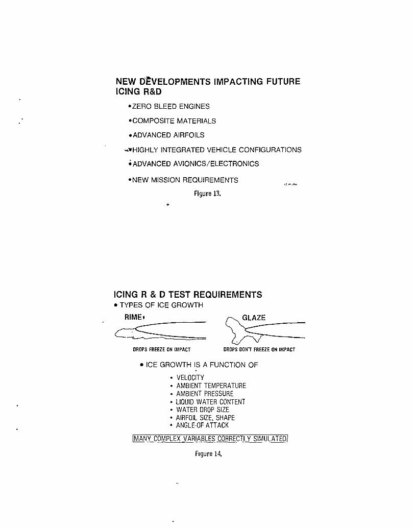
Ice accumulatIon and growth 1S a very complex phenomena. The two types of Ice growth, Rlme and Glaze, are depIcted In FIg. 14. These can be very dIfferent and have very dIfferent effects on the flow over the surface the Ice IS accumulatIng on. Both types of Ice growth, however, are a functIon of a number of dIfferent varIables whIch are lIsted on the fIgure. Many of these are envIronment related and translate dIrectly Into capabIlItIes that an ICIng research facIlIty must have. Such a facIlIty must be a wInd tunnel that can SImulate the speed range over whIch Ice can accumulate. Because the Ice growth IS a functIon of the aIr velocIty a large speed range IS reqUIred. The facIlIty must also SImulate proper altItude pressure and temperature, agaIn because the Ice growth IS a functIon of these parameters. An ICIng facIlIty must also have a method of IntroduCIng mOIsture Into the aIrstream In a varIety of forms and amounts matchIng what eXIsts In the atmosphere.
Ice accretIon does not scale wIth the sIze of the surface beIng Iced. ThIS IS demonstrated In FIg. 15. Smaller obJects are more effICIent Ice collectors than large obJects. Other factors, such as water droplet sIze relatIve to the obJect sIze and the water content In the aIr, also enter Into the scalIng phenomena. Attempts have been made to ana1yt1ca11y account for sca11ng effects, but have been unsuccessful. ThIS IS due to the complexIty of the problem and the scarcIty of experImental data Because the scalIng pheno~ena IS complex and not well understood It IS necessary to perform

test1ng at large scale. for an 1c1ng fac111ty 1S perm1t large scale model blockage effects.
Therefore, a requ1rement that 1t be large enough to test1ng w1thout adverse
Currently the largest 1c1ng research w1nd tunnel 1S the NASA Lew1s Research Ce~ter IC1ng ~esearch Tunnel (IRT) Wh1Ch has a 6 foot by 9 foot test sectIon. The IRT 15 heavIly used because of lts very un1que 1c1ng capab111t1es, however, 1t has sone 11m1tat1ons. The IRT 1S a sea level tunnel and therefore does not slmulate true a1t1tude pressures. The operat1ng 11ne of the IRT 1S shown on F1g. 16. The IRT speed capab111ty 1S 11m1ted to J1lues equ1valent to Mach 0.4. As can be seen from th1S f1gure there 1S a large port10n of the fl1ght envelope where 1c1ng cond1tlons eX1st that no large test fac1l1ty has the capab111ty of slmu1atlng. Also 1n F1g. 16 1S a sketc~-of a tYP1ca1 full scale 1nlet/nacelle/splnner for a turboprop propuls10n system mounted 1n the IRT test sectlon. Even though the IRT 1S the largest facll1ty of ltS k1nd, the test hardware shown would prov1de h1gh blockage levels.
The facll1ty capabll1tles requ1red for conduct-nq adverse weather research are summar1zed ln
Flq. 17. IClng research has been used as the 1 1lustratlve example to develop these crlterla, but the sa~e capab111tles are what 1S needed for the uther types of adverse weather as well. There 1S ~o fac111ty 1n eXlstence that has all these necess 'rj capab111tles for advers p weather testlng.
flew Test Facll1ty Requlrements Summary
The abl1lty to correctly slmu1ate the enV1ron~ental and fllght condltl0ns needed to study and .esolve the technologlca1 challenges assoc1ated ;'th the proposed future alrcraft concepts wl11 be crltlcal for achlevlng the potent1a1 they offer. !n order to perform the research necessary to develop these technolog1es new test fac111ty caprb111tles wl11 be requlred (Flg. 18). The new hlghly lntegrated systems prevlously dlscussed wlll rpqu1re a test facl11ty that has the capablllty of ~prfornlng tests wlth an actual operat1ng propulSlcn system and the-propulslon system must operate the sane as lt does ln actual fllght. ThlS requ1res correct slmulatlon of both altltude press~re and temperature. Such a fac111ty must be large enough to accept a full scale propu1s10n system as well as a port1on of the a1rframe. In order to properly evaluate lntegratlon effects a w1nd tunnel conflguratl0n lS requlred that can slmulate a broad subsonlc speed range. Approprlate accormodatl0ns must be made to permlt the operat10n of the propulslon system (l.e., an exhaust scoop). In order to perform rea11stlc adverse "cather research requlres all of the above cap)b1l1t1es as well as a means of lntroduc1ng rOlsture ln the proper amounts and forms (clouds, n1st, ra1n, etc.).
Altltude Wlnd Tunnel (AWT)
A proposal has been made to modlfy the eXlstlng dormant Altltude Wlnd Tunnel (AWT) at the NASA Lew1s Research Center to provlde a faclllty that would have all of the requlred capabl11tles for both propu1s10n system lntegratlon and adverse heather testlng. ThlS faclllty, shown ln Flg. 19, was bUllt ln 1944 and was used as a refrlgerated
4
a1tltude wlnd tunnel for propu1s10n system testlng for approxlmate1y 15 years. From 1960 to 1970 lt was used as a space power chamber and has been dormant Slnce 1970.
The proposed modlflcatlons to the eXlst1ng facl11ty would result ln the deslgn shown schematlca11y 1n Flg. 20. The test sectl0n 1S octagonal measurIng 20 ft across parallel SIdes. Mach numbers rang1ng from near 0 to more than O.g w111 be achlevable w1th large blockage models (10 to 12 percent) lncludlng complete operatlng propu1s10n systems. The eXlst1ng central Lewls altltude exhaust system wll1 provlde altltude var1at10n from sea level to greater than 55 000 ft. The tunnel refrlgeratlon system wl11 allow tunnel total temperature varlatlons from -40 to 60 OF.
The AWT standard wlnd tunnel components are shown ln Flg. 21. The drlve power for the fac111ty WIll be provlded by two 30 000 hp e1ectr1c motors. Each can be run lndependently or they can be run ln serles dependlng on the operatIng requlrements. The drlve fan wl11 be a hlgh efflclency deslgn wlth two rotor stages each contalnlng 17 blades. The number of stator vanes (28 per stage) was selected to mlnlmlze the lnteractlons between the vanes and rotor blades and thus mlnlmlze the nOlse wlthln the tunnel. The heat exchanger wl11 provlde coollng to remove the heat added to the tunnel alr by the drlve fan and to slmulate the deslred altltude statlc temperatures. The flow condltloners wl1l conslst of a honeycomb sectlon and removable screens. The screens wlll be removed durlng adverse weather testlng. The flow condltloners wl11 provlde good quallty (low turbulence) flow to the test sectlon. The octagonal test sectlon lS fltted wlth boundary layer bleed slots runnlng along each of the elght corners. The test sectlon wll1 be surrounded by a plenum chamber WhlCh can be pumped down to low pressures to bleed the boundary layer out of the test sectlon to mlnlm1ze tunnel wall lnterference effects.
The speclal features of the AWT WhlCh help provlde ltS unlque capabllltles are shown ln F1g. 22. The turnlng vanes ln the two corners downstream of the test sectlon wlll be heated. ThlS feature lS needed to prevent lce bU1ldup on the vanes dur1ng adverse weather testlng. The heat exchanger w11l be connected to a 21 000 ton capaclty, Freon-22, two phase refrlgeratlon system. ThlS system w1l1 permlt operatlon at statlC temperatures that are encountered at altltudes ranglng from sea level to ln excess of 55 000 ft. The water spray system wl11 be lnserted ln the tunnel for adverse weather testlng (l.e., lClng condltlons, heavy raln, snow). Th1S system wl11 have the capabl11ty to lntroduce water ln varl0US droplet Slzes and water content levels. The spray bar system wlll be removed when not ln use to preserve test sectlon flow quallty for aerodynamlc tests. An englne exhaust scoop wlll be lncorporated so that full scale englnes can be operated and tested ln the faclllty. The scoop wlll capture and exhaust the englne waste products so that the alr clrculatlng ln the tunnel wl11 not be contamlnated. The plenum evacuatlon system wlll permlt the use of large hlgh blockage models at hlgh subson1c speeds. The boundary layer WIll be drawn off by pump1ng down the plenum. ThlS wl11 mlnlmlze the wall lnterference effects and permlts testlng of larger slzed models. The alr drawn off wl11 be compressed
and Injected back Into the tunnel Just downstream of the drIve fan. Plans for thIs facIlIty also Include acoustIc testIng, and therefore, some acoustIc features have been Incorporated Into the desIgn. As mentIoned before, the vane/blade ratIo selected for the fan was chosen to mInImIze nOIse. A four rIng sIlencer wIll be lo~ed Just downstream of the heat exchanger and there wIll be acoustIc treatment In the turnIng vanes and the walls of the two corners upstream of the test sectIon. The test sectIon wIll have lnsertab1e acoustIc panels and several dIfferent confIguratIons are beIng consIdered that would choke the flow at the end of the test sectIon, to prevent downstream nOIse from propagatIng forward. WIth all of these features the background nOIse level In the test sectIon IS expected to be less than 120 dB.
DetaIls of the test sectIon are shown In FIg. 23. The octagonal shape provIdes a convenIent geometry for the use of boundary layer control bleed slots whIch permIts good transonIc performance WIth large blockage models. The octagonal shape also faCIlItates use of flat hIgh qualIty optIcal WIndows for ICIng research and for the use of laser measurement systems. ThIS shape prOVIdes a convenIent SIdewall deSIgn for easllY·lnstalllng 3nd lnterchanglng acoustIc p~nels. Model entry Nl11 be from the bottom of the test sectIon. The tunnel floor wlll be mounted on screw-Jacks whIch Nl11 a110N It to be raIsed and lowered. The models W III be brought onto the tunnel fl oor at the surroundlng shop level and then WIll be raIsed Into place. Models can be mounted from elther the slde~a11 trunnlons or a floor plate In the center of the test sectlon. These features WIll allow for rapId model InstallatIon and removal from the test sectIon thereby prOVIdIng hIgh experImental productlvlty. A force balance WIll be attached to the tunnel floor plate to allow thrust measurements of propulslon system performance. A conSIderable analytIcal and physlcal modelIng effort IS underway to assure thls deslgn WIll prOVIde the reqUIred test envIronment and performance. 4 ,b
ConcludIng Remarks
The modIfIed AltItude WInd Tunnel deSIgn WIll prOVIde all the necessary faCIlIty capabIlItIes for conductIng propulSIon system IntegratIon and adverse weather research. The capabIlItIes of the rehabllltated AWT relatIve to those needed for propulSIon system IntegratIon research, are summarIzed In FIg. 24. ThIS faCIlIty would SImulate both true altItude pressure ~nd temperature con- • currently over the flIght range of Interest. It lS a wlnd tunnel confIguratIon and therefore would provlde the proper flow fIeld over the entIre test artlcle. It has a large test sectIon (20 ft across parallel SIdes), whIch WIth the plenum evacuatIon system to reduce wall Interference effects, WIll permIt testIng of full sIze hardware IncludIng actual propulSIon systems along WIth a SIzeable portIon of the aIrcraft. It Includes an exhaust scoop to remove engIne waste products.
The capabllltles of the rehabIlItated AWT relatlve to those needed for adverse weather research, as Illustrated for ICIng research, are summarIzed In FIg. 25 and also In Ref. 6. As stated above, thIS faCIlIty would correctly SImulate both altItude pressure and temperature. The proposed AWT
5
conflguratlor also Includes a method for IntroducIng mOIsture Into the test sectIon In varIous forms and amounts. ComparIsons are also made WIth the LeWIS ICIng Research Tunnel whIch IS the largest and most heaVIly used lClng faCIlIty In thIS country. As can be seen from the plot the IRT IS lImIted to operatIon along a lIne from Mach 0 to 0.4 at sea level pressures. The AWT confIguratIon, on the other hand, would cover a very large speed/ altItude envelope. FIgure 25 also Includes sketches shOWIng the sIze of the proposed AWT relatIve to the LeWIS IRT. The sketches show the same lnlet/ nacelle model mounted In both tunnels. As can be seen the blockage In the IRT faclllty would be qUIte hIgh, however, that would not be the case In AWT, In fact, a full sIze propeller (14 ft dIameter) could also be Included and operated.
The abIlIty to correctly SImulate the envIronmental and flIght condItIons needed to study and resolve the technologIcal challenges assocIated WIth the proposed future aIrcraft concepts WIll be crltlcal for achIeVIng the potentIal that they offer. UnIque ground test faCIlItIes are used to SImulate the needed flIght envIronment and thereby SIgnIfIcantly reduce the tIme, cost, and rIsk that would be assocIated WIth flIght testIng. Ground test faCIlItIes also prOVIde the more accurate measurement systems and more fleXIble test condItIons that are needed to fully understand complex technIcal phenomena and resolve technologIcal questIons.
An evaluatIon of eXIstIng U.S. ground test faCIlItIes has revealed a crItIcal VOId In the capabIlIty to prOVIde the approprIate condItIons for conductIng accurate evaluatIons of the Integrated technologIes assoclated WIth propulslon/ aIrframe IntegratIon and all weather operatIon. To fIll thIS VOId LeWIS has proposed to rehabIlItate and modIfy the eXIstIng dormant AltItude WInd Tunnel faCIlIty that WIll SImultaneously satIsfy the test requIrements needed to successfully evaluate and resolve the technologIcal challenges assocIated WIth future hIgh potentIal aeronautIcal vehIcles.
References
1. AeronautIcs and Space EngIneerIng Board, CommIssIon on EngIneerIng and TechnIcal Systems, NatIonal Research CouncIl, "AeronautIcs Technology POSSIbIlItIes for 2000: Report of a Workshop," NatIonal Academy Press, WashIngton, D.C., 1984.
2. WhItfIeld, J.D., and HartIn, J.P., eds. "AerodynamIC TestIng - A Look at Future ReqUIrements," AIAA Paper 78-765, Apr. 1978.
3. ExecutIve OffIce of the PreSIdent, OffIce of SCIence and Technology PolICY (OSTP), "Report of the AeronautIcal PolICY ReVIew CommIttee," Nov. 9, 1983.
4. Towne, C.E., Povlnelll, L.A., Kunlk, W.G., Muramoto, K.K., McClallln, K.L., Hughes, C.E. and Levy, R, "AnalytIcal ModelIng of CIrcuIt AerodynamICs In the New NASA LeWIS AltItude WInd Tunnel," AIAA Paper 85-0380, Jan. 1985.

5. Abbott, J.M., Dledrlch, J.H., Groeneweg, J.F., Povlnelll, L.A., Reld, L., Relnmann, J.J., and Szuch, J.R •. "Analytlcal and Physlcal Modellng Program for the NASA LeW1S Research Center's Altltude Wlnd Tunnel (AWT)," AIAA Paper 85-0379, Jan. 1985.
'oJ;.--
6
6. Blaha, B., and Shaw, R.J., "The NASA Altltude Wlnd Tunnel: Its Role ln Advanced IClng Research and Development," AIAA Paper 85-0090, Jan. 1985.

.-FUTURE OF AERONAUTICS
- MAJOR ADVANCEMENTS STILL ACHIEVABLE
- SIGNIFICANT TECHNICAL CHALLENGES EXIST
-..HNPRECEDENTED DEGREE OF INTEGRATION
- INTERACTION OF PROPULSION SYSTEM COMPONENTS
- EFFECTS OF INSTALLATION ON PROPULSION SYSTEM
Figure 1. ..
FUTURE AERONAUTICAL SYSTEMS
Flgu re 2.

HIGH SPEED TURBOPROP PROPULSION
Figure 3. C-84-1340
Figure 4. C-84-1325

C-84-1343
Figure 5 •
. ADVANCING BLAOE CONCEPT (ABC) .
Figure 6.

PROPULS"fON SYSTEM INTEGRATION TEST REQUIREMENT FUTURE SYSTEMS CONVENTIONAL
TURBOFANS E ~-l= -B-]
~ Eu ~-l Bjli-J
~f---:--i ~
MACH 04 TO 05 LINtrORM INFLOW UNCOUPLED FROM
EXTERNAL AIRSTREAM
EXTERNAL FLOW SIMULATION AND FULL/LARGE SCALE
Figure 7.
PROPULSION SYSTEM INTEGRATION TEST REQUIREMENT
50
40
30 ALTITUDE (KFT) 20
SEA LEVEL TUNNELS
• 3 TIMES FLIGHT DENSITY
- EXCESSIVE BLADE AIR LOADS
- 3 TIMES POWER
• REDUCED FLUTIER SPEEDS
MACH NUMBER
I CORRECT AMBIENT PRESSURE I Figure 8.

PROPULSION SYSTEM INTEGRATION TEST REQUIREMENT 100
STAGNATION 50 TEMPERATURE, 0
'F -50 o
..... -
UNREFRIGERATED TUNNEL
~3 2 6
MACH NUMBER 113' TEMPERATURE DIFFERENCE RESULTS IN 10 TO 12% OVERSPEED TO MAINTAIN SIMILARITY
MISMATCH BETWEEN ENGINE EXCITATIONS & BLADE NATURAL FREQUENCIES
ICORRECT AMBIENT TEMPERATURE I
Figure 9.
PROPULSION SYSTEM INTEGRATION TEST REQUIREMENTS SUMMARY
• EXTERNAL FLOW SIMULATION
• CORRECT PRESSURE AND TEMP~RATURE
• FULL/LARGE SCALE
Figure 10.
SUITABLE FACILITY
NON EXISTENT

ADVERSE WEATHER OPERATION
C-84-1413.
Figure 11.
ICING R&D APPLICATIONS
• PROPULSION SYSTEMS
-INLETS - CARBURETORS -FAN - PROPELLERS
fI FIXED AND ROTARY WING AIRCRAFT
- ADVANCED AIRFOILS - HIGH LIFT DEVICES
CD-SF
Figure 12.
NEW D~VELOPMENTS IMPACTING FUTURE ICING R&D
-ZERO BLEED ENGINES
-COMPOSITE MATERIALS
- ADVANCED AIRFOILS
...... HIGHLY INTEGRATED VEHICLE CONFIGURATIONS
• ADVANCED AVIONICS/ELECTRONICS
-NEW MISSION REQUIREMENTS
Figure 13.
ICING R&D TEST REQUIREMENTS • TYPES OF ICE GROWTH
RIME,
~::::=:::::== ~---DROPS FREEZE ON IMPACT DROPS DON'T FREEZE ON IMPACT
• ICE GROWTH IS A FUNCTION OF
• VELOCITY • AMBIENT TEMPERATURE • AMBIENT PRESSURE • LlOUID WATER CONTENT • WATER DROP SIZE • AIRFOIL SIZE. SHAPE • ANGLE·OF ATTACK
IMANY COMPLEX VARIABLES CORRECTLY SIMULAJ1Q]
Figure 14.

EFFECT Q.E SIZE OF OBJECT ON ICE ACCRETION
..sO
025 ft DIAMETER
"",-
o 1 ft
DIAMETER
SIMPLE GEOMETRIC SCALING NOT CORRECT - VELOCITY, LIQUID WATER CONTENT, TIME OF ACCRETION, AND MEAN DROPLET SIZE MUST ALSO BE SCALED
FIgure 15.
ICING R&D TEST REQUIREMENTS 50000
40000 1001 ALTITUDE,
ft
TEST IN IRT FACILITY
30000
20000
10000
o 2 4 6 10
MACH NUMBER I EXISTING GROUND FACILITIES DO NOT SIMULATE FLIGHT CONDITIONS AND SCALE I
(D"'14~
Figure 16.

ICING R&D TEST REQUIREMENTS SUMMARY
• FLIGHT ALTITUDE SIMULATION
• CORRECT FLIGHT SPEEDS
• -CORRECT MOISTURE CONTENT AND FORM
• FULl/LARGE SCALE
or
Figure 17.
NEW TEST FACILITY REQUIREMENTS
SUITABLE FACILITY
NON-EXISTENT CD U I(JII~
• CONCURRENT PRESSURE AND TEMPERATURE SIMULATION OF ALTITUDE
• LA8GE SCALE TEST ARTICLES
• FULL SUBSONIC SPEED RANGE
• WIND TUNNEL CONFIGURATIONAERODYNAMICS/ACOUSTICS
• PROPULSION SYSTEM OPERATION/SIMULATION
• ICING, HEAVY RAIN CAPABILITY
I NO EXISTING NOR PLANNED FACILITY MEETS THESE NEEDS I Figure 18.

ALTITUDE WIND TUNNEL
Figure 19.
ALTITUDE WIND TUNNEL
TEST SECTION
/-'" "T CAPABILITIES
I * 1 20FT
",_/1tL MACH NUMBER ALTITUDE TOTAL TEMPERATURE
Figure 20.
o TO 0.9 + o TO 55 000 FT + -40 0 TO 60 0 F

. .
STANDARD WIND TUNNEL COMPONENTS
~ TWO 30K HP DRIVE MOTORS ()c[cc~ 1-------'«0-rl+th+-~
..... -
20 ft dlam TEST SECTION
HEATED TURNING VANES
PLENUM EVACUATION SYSTEM
Figure 21.
ENGINE EXHAUST SCOOP
Figure 22.
TUNNEL HEAT EXCHANGER
FLOW CONDITIONERS
REMOVABLE WATER
SPRAY SYSTEM
-..

TEST SECTION FEATURES
• OCTAGONAL CROSS SECTION
• SLOnED WALL WITH PLENUM
• FLAT WINDOWS
• FORCE BALANCE
• REMOVABLE ACOUSTICAL WALLS
• BOnOM MODEL ENTRY
• RAPID MODEL ACCESS
Figure 23.
AWT SATISFIES PROPULSION SYSTEM INTEGRATION TEST REQUIREMENTS
CONCURRENT PRESSURE & TEMPERATURE
50000
40000
ALTITUDE. 30000
" 20000
l-f--<-- f-
\- i- HI
.... i:~ <w.,,_
....-"
100
50
STAGNATION TEMPE~ATURE 0
-\--
Figure 24.
(DUI .. H

>4-
A WT SATISFIES ICING TEST REQUIREMENTS
50000
40000
ALTITUDE, 30 000
ft 20000
10 000
a
AWT 20 II TEST SECTION
• CORRECT FLIGHT SPEEDS • LARGE SIZE
2 4 6 8
MACH NUMBER
Figure 25.
TEST IN IRT FACILITY
1 a

1 Report No NASA TM-86921 AlAA-85-0314
4 Title and Subtitle
2 Government Accession No
The Altitude Wi nd Tunnel (AHT) - A Uni que Fad 1 i ty for Propulsion System and Adverse Weather Testing
7 AuthOr(s)
Roger Chamberlin
9 Performing Organization Name and Address
National Aeronautics am! Space Administration Lewls Research Center Cleveland, Ohio 44135
12 Sponsoring Agency Name and Address
Natlonal Aeronautics and Space Administration Washlngton, D.C. 20546
15 SJPplementary Notes
3 Recipient's Catalog No
5 Report Date
6 Performing Organization Code
505-40-74 8 Performing Organization Report No
E-2415 10 Work Unit No
11 Contract or Grant No
13 Type of Report and Period Covered
Technical Memorandum 14 Sponsoring Agency Code
Prepared for the Twenty-third Aerospace Sciences Meetlng sponsored by the Arnencan Instltute of Aeronautics and Astronautics, Reno, Nevada, January 14-17, 1985.
16 A~stract
A need has arlsen for a new wind tunnel facillty wlth unique capabillties for testlng propulsion systems and for conducting research in adverse weather conditlons. New propulslon system concepts, new alrcraft conflguratlons with an unprecedented degree of propulsion system/alrcraft lntegration, and requirements for alrcraft operation in adverse weather dlctate the need for a new test faclllty. Requlred capabilities include simulation of both altitude pressure and temperature, large Slze, full subsonic speed range, propulslon system operatlon, and weather simulation (i.e., iClng, heavy rain). A cost effectlve rehabll1tatlon of the NASA Lewis Research Center's Altitude Wind Tunnel (AWT) wlll provlde a facility with all these capabi11ties.
17 Key Words (Suggested by Author(s))
Wind tunnels; Propulsion; Propulsion system integration testing; Adverse wea ther testi ng
lB Distribution Statement
Unclassified - unllmited STAR Category 09
19 Security Classlf (of this report)
UnClaSSlfled 20 Security Classlf (of this page)
UnC1aSSlfled 21 No of pages
"For sale by the National Technical Information SerVice, Springfield, Virginia 22161
22 Price·

End of Document