the aerospace energy laboratory: hardware software ... · tion in the servicing of flight-critical...
TRANSCRIPT

-.r ,_
NASA Technical Memorandum 101706
The Aerospace Energy SystemsLaboratory: Hardware andSoftware ImplementationRichard D. Glover and Nora O'Neill-Rood
(NASA-TM-IOI706) THE A_RPSPACE ENERGY
SYSTEMS LA6NRATORY: HARDWARE ANn SOFTWARE
IMPLEMENTATION (NASA) 21 p CSCL 09_
G3/o2
NQO-ZOOlO
unclas
02'34970
VJuly 1989
,,i
NASANational Aeronautics and
Space Administration
https://ntrs.nasa.gov/search.jsp?R=19900001294 2018-08-01T17:40:24+00:00Z

P
I|

NASA Technical Memorandum 101706
The Aerospace Energy SystemsLaboratory: Hardware andSoftware Implementation
Richard D. Glover and Nora O'Neill-RoodAmes Research Center, Dryden Flight Research Facility, Edwards, California
1989
tUASANational Aeronautics andSpace AdministrationAmes Research Center
Dryden Flight Research FacilityEdwards, California 93523-5000


THE AEROSPACE ENERGY SYSTEMS LABORATORY:
HARDWARE AND SOFTWARE IMPLEMENTATION
Richard D. Glover * and Nora O'Neill-Rood t
NASA Ames Research Center
Dryden Flight Research Facility
Edwards, California
Abstract
For many years NASA Ames Research Center, Dry-
den Flight Research Facility has employed automa-
tion in the servicing of flight-critical aircraft batteries.
Recently a major upgrade to Dryden's computerized
Battery Systems Laboratory was initiated to incorpo-
rate distributed processing and a centralized database.
The new facility, called the Aerospace Energy Sys-
tems Laboratory (AESL), is being mechanized with
iAPX86 and iAPX286 hardware running iRMX86.
This paper describes the hardware configuration andsoftware structure for the AESL.
Nomenclature
A/DADC
AESL
Ames-Dryden
BSC
BSL
DAC
DPR
DSDD
IEEE
I/ONDP
SBC
SBX
SCP
qTL
analog-to-digital
analog-to-digital converter
Aerospace Energy Systems
Laboratory
NASA Ames Research Center,
Dryden Flight Research Facility
Battery Station Controller
Battery Systems Laboratory
digital-to-analog converter
dual port RAM
double-sidcd, double densityInstitute of Electrical and Electronic
Engineers
input/output
numeric data processor
single-board computer
single-board expansion
status and control panel
transistor-transistor logic
Introduction
For many years the NASA Ames Research Center's
Dryden Flight Research Facility (Ames-Dryden) has
"Aerospace Engineer.
tSystems Programmer.
been operating research aircraft in which rechargeable
batteries serve as important power sources for vari-
ous flight-critical systems. Such batteries must un-
dergo periodic servicing to verify integrity, capacity,
and load-carrying ability for flight safety recertifica-
tion. Bccause of the large number of aircraft, each hav-
ing several sets of batteries assigned to it, the servic-
ing workload is considerable. Ames-Dryden has been
incorporating automation techniques to lower the cost
of battery servicing, while at the same time improving
quality and reducing turnaround times.
The present Ames-Dryden Battery Systems Labo-
ratory (BSL) evolved over 20 years, based on goalsestablished in the 1960s. In 1970 automation was first
introduced into the BSL using a commercial minicom-
puter and a 200-channel scanner employing a multi-
plexed analog-to-digital converter (ADC). This sys-
tem was so successful that in 1973 the minicomputer
was upgraded and the ADC expanded to 800 channels.
A modernization effort beginning in 1979 brought the
system up to 1024 ADC channels, and a new computer
system allowed control over 40 battery-charging sta-
tions (Stewart, 1983).
In 1987 it was decided that the BSL required further
modernization to meet projected future requirements
for battery servicing at Ames-Dryden. The second-
generation BSL will be called the Aerospace Energy
Systems Laboratory (AESL) (Glover, 1988b); proto-
type elements of this new system are nearing opera-
tional status. This report discusses the implementa-
tion of the new facility based on prior Muhibus sys-
tems engineering done at Ames-Dryden to support
aircraft testing (Glover, 1983; Glover, 1987; and
Glover, 1988a).
Evolution of the AESL
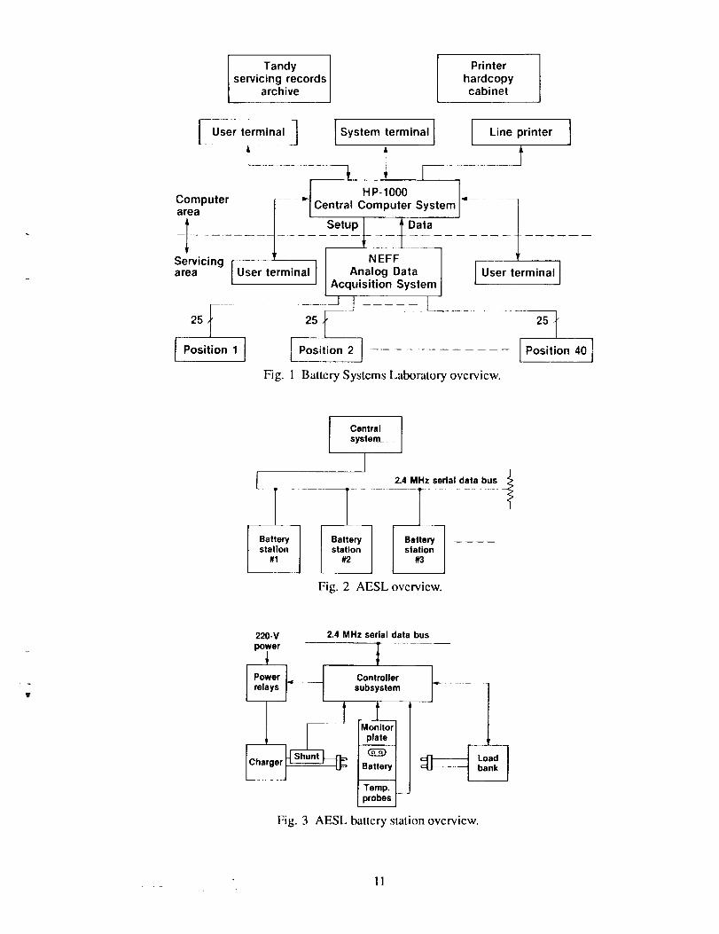
Figure 1 is an overview of NASA's present Bat-
tery Systems Laboratory (BSL). The system employs
a minicomputer and a centralized analog data acqui-
sitionsystemto receive25datachannelsfromeachof 40batteryservicingpositions.Althoughnotshownin figure1,theminicomputerhasshutdowncommandauthorityoverthechargerateachposition,Servicingrecordsaresenttothelineprinterandfiledashardcopyforlaterreference.Aportionofthishardcopylistingisthenmanuallyenteredintoaseparateservicingrecordarchivesfor easeof access.
After manyyearsof automatedbatteryservicing,theBSLhasreachedtheendof itsusefulservicelife.Hardwareandsoftwaremaintainabilityhasdiminishedandthearchitecturehasinherentsinglepointfailures.Severalshortcomingshavealsobeenidentified:theanalog-to-digital(A/D) samplerateis too low,A/Dcalibrationisdifficult,it cannotsensebatterytemper-ature,andampere-hoursintegrationaccuracyis low.Followingadetailedstudyof theBSLanditsopera-tionaldeficiencies(Glover,1988b),thefollowingre-quirementsfor anewfacilityweredefined:
ImproveReliability
• New state-of-the-art hardware
• Decentralized architecture to reduce wiring
• Industrial grade real-time operating system
• Fault-tolerant partitioned system philosophy
• Stand-alone operations of system components
Upgrade Central System
• Incorporate battery-specific servicing historyarchives
• Incorporate project-specific applications database
• Incorporate battery-type characterisics database
• Incorporate independently powered clock andcalendar
Improve Safety
• Incorporate cell emissions detector
• Incorporate case temperature sensing
• Incorporate runaway cell detection algorithm
• Incorporate dcadman timers in control loops
• Provide independent primary power shutdown
relays
2
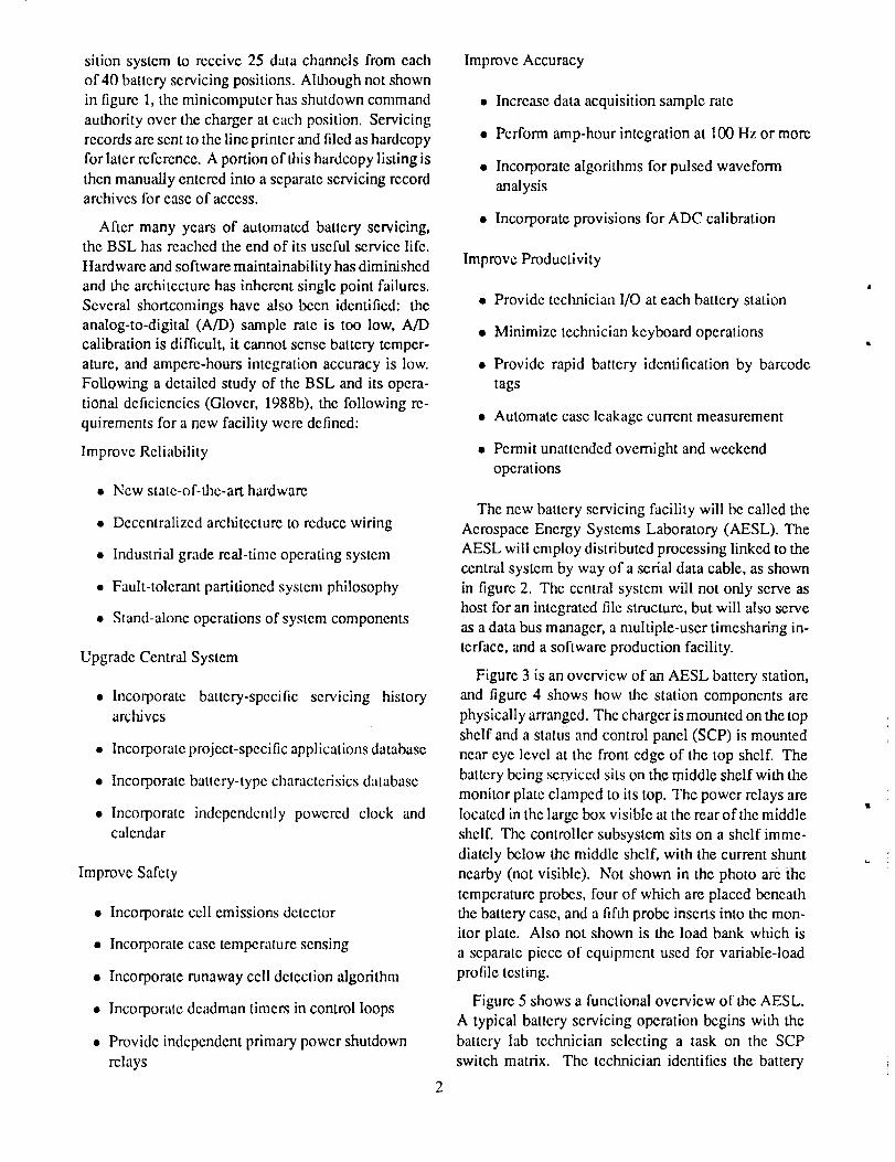
Improve Accuracy
• Increase data acquisition sample rate
• Perform amp-hour integration at 100 Hz or more
• Incorporate algorithms for pulsed waveform
analysis
• Incorporate provisions for ADC calibration
Improve Productivity
• Provide technician I/O at each battery station
• Minimize technician keyboard operations
• Provide rapid battery identification by barcode
tags
• Automate case leakage current measurement
• Pem_it unattended ovemight and weekend
operations
The new battery servicing facility will be called the
Aerospace Energy Systems Laboratory (AESL). The
AESL will employ distributed processing linked to the
central system by way of a serial data cable, as shown
in figure 2. The central system will not only serve as
host for an integrated file structure, but will also serve
as a data bus manager, a multiple-user timesharing in-
terface, and a software production facility.
Figure 3 is an overview of an AESL battery station,
and figure 4 shows how the station components are
physically arranged. The charger is mounted on the top
shelf and a status and control panel (SCP) is mounted
near eye level at the front edge of the top shelf. The
battery being serviced sits on the middle shelf with the
monitor plate clamped to its top. The power relays are
located in the large box visible at the rear of the middle
shelf. The controller subsystem sits on a shelf imme-
diately below the middle shelf, with the current shunt
nearby (not visible). Not shown in the photo are the
temperature probes, four of which are placed beneath
the battery case, and a fifth probe inserts into the mon-
itor plate. Also not shown is the load bank which is
a separate piece of equipment used for variable-load
profile testing.
Figure 5 shows a functional overview of the AESL.
A typical battery servicing operation begins with the
battery lab technician selecting a task on the SCP
switch matrix. The technician identifies the battery
to be servicedby scanningits affixedbarcodetagusingthehand-heldbareodereadergunattachedtoeachbatterystation.He identifieshimselfastheser-vicingtechnicianby scanninga personalizedcredit-card-sizedbareodeID. Theappropriatespecificationfilesarefetchedfromthecentralsystem,startingwiththebatteryspecificationfile usinga pathnamecon-structcdfromthebatterybarcodetag;theremainingfilesarefetchedusingpathnamesderivedfrominfor-mationfoundin the batteryspecificationfile. Thetechnicianfastensthemonitorplateandtemperatureprobestothebattery,pressestheEQUIPPOWERbut-ton(whichsuppliespowertothecharger)ontheSCP,adjuststhechargerwith theappropriatesetting,andstartstheservicingoperationbyselectingrunmodeontheSCP.
Duringtheoperation,thecontrollermonitorsallthevariablesandsensesbothnormalend-of-runandout-of-limitsconditions.At thecompletionof theopera-tion, thestationcontrollershutsdownthechargerbywayof primarypowerrelaysexternalto thecharger,alertsthetechnicianwiththesoundingof thebeeperalarmanddisplayof anendof operalionstatusmes-sageon theSCP,andtransfersthedatagenerateddur-ingtheoperationtothecentralsystemarchives.
DatabaseSpecificationand File Structure
areadded.Thisrequirescreationof additionaldirec-toriesandeditingof newspecificationfiles. Second,theremustbeutilitiesfor decodingspecificationfilesandencodingservicingdatafiles. Third, to permitefficientaccessto theservicingdatafiles,theremustbeapplicationutilitiesforscanning,cross-correlating,andextractingthe desiredinformation.Last, theremustbeanefficientmeansforcullingolderdatafilessotheymaybestoredoff-line.
Twoalternatemethodsof structuringthespecifica-tionanddatafileswereconsidered:ASCII text files
and a combination of ASCII and raw numeric. A por-
tion of both the specification and data file contents was
expected to be ASCII, while the remainder was mostly
floating-point numeric. It was decided to design the
entire structure using only ASCII-encoded text files.
The disadvantage of this strategy is that the files are
larger, while the advantage is ease of editing. The
format chosen was free-field using parameter identi-
fication tags and field delimiters as opposed to fixed-
length fields, thus offering maximum flexibility. Fig-
ure 7 shows an example of a cell specification file il-
lustrating the type of parameters and characteristics in-
cluded. Figure 8 shows an example of a battery servic-
ing data file.
Central System Mechanization
One of the first elements to be designed for the
proposed new facility was the integrated specifica-
tions database and battery servicing records archives
file structure shown in figure 6. The root directory
BA'FI'ERY will contain second-level battery directo-
ries with names corresponding to their eight-digit bar-code numbers. Each of these second-level directories
includes a single specification file and any number of
data files created during battery servicing operations.
The names of thcse data files will be generated fromthe date and time at the moment of file creation. There-
fore, a file created at 8:30 a.m. on November 15, 1988
would be named 881115083000. Within the root direc-
tory CELL will reside the cell specification files, one
for each type of cell used in the various types of batter-
ies. The root directory PROJECT will contain second-
level project directories. Each second-level project di-
rectory will contain a single project specification file
and also may contain any number of variable-load pro-file files.
Management of this integrated data structure has
several operational aspects. First, the structure must
be expandable as new batteries, cell types, and projects
As shown in figure 9, the AESL central system con-
sists of a two-chassis Intcl System 310 processor on
the left, a Wyse Model 60 terminal in the center, and
a Dataproducts M220 line printer on the right. The
310 main subsystem chassis mounted on top has in-
stalled a Memtech iBC magnetic bubble cassette mod-
ule, a 5.25-in. DSDD floppy diskette drive, and a 0.25-
in. tape cartridge drive. The 311 peripheral expan-
sion subsystem chassis on the bottom has installed
two Seagate ST251 hard disk drives and associated
power supplies.
Table 1 shows the hardware complement installed
in the 310 cardcage. The processor is an SBC 286/12
that has an 80287 numeric data coprocessor installed,
plus a SBX344A BITBUS interface module installedat SBX connector J6. The SBC544 and SBC548 com-
munications controllers provide a total of 12 chan-
nels of serial I/O. The SBC214 provides manage-
ment of the hard disks, the floppy drive, and the tapedrive. The Central Data motherboard hosts an assort-
ment of supporting SBX modules. The SBX258 mod-ule interfaces to the iBC bubble cassette unit. The
SBX351 serial module provides a utility RS232 port.

TheSBX251magneticbubblememorymodulepro-vides128Kbytesof auxiliaryscratchpad.TheCom-
puter Modules LSBX-Super module is powered by a
lithium battery and provides clock/calendar services,
a programmable timer interrupt, and 8 Kbytes of non-volatile static RAM.
The operating system used in the AESL central sys-
tem is RMX86 Release 7 containing a full complement
of system services including Universal Development
Interface (UDI). The program is configured for the pe-
ripherals described above using the interrupt mapping
shown in figure 10. The iBC bubble cassette unit is
configured as unit :B0: and the SBX251 auxiliary bub-
ble memory is configured as unit :B 1:. The hard drives
are configured as units :W0: and :Wl :, with :W0: serv-
ing as the system device and :WI: serving as the repos-
itory for the integrated database structure. For both the
Central system applications and BSC software :W0: is
formatted for 5000 files and hosts the software pro-
duction tools and miscellaneous source language ele-
ments. On the assumption that virtually all its files will
be less than 1024 bytes in length, :WI" is formatted
for 38,000 files. No software is yet in place to service
either the multiuser environment or the BITBUS, and
the central system has thus far only been used for the
production of BSC software.
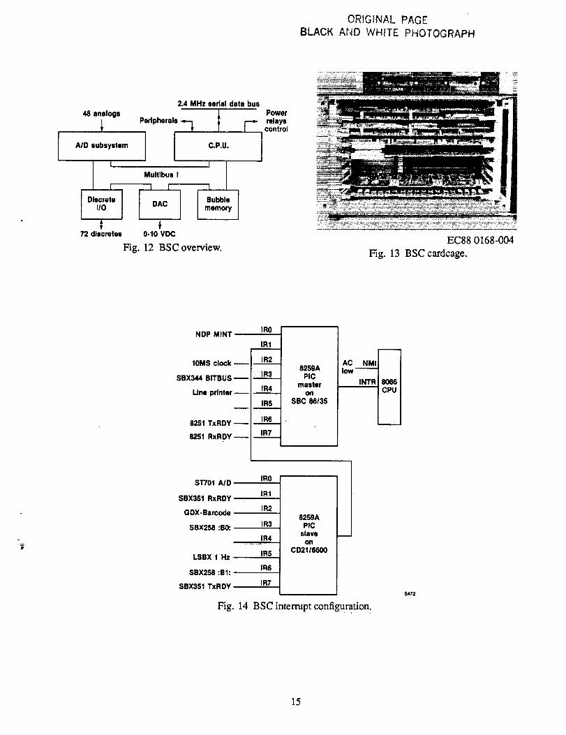
Battery Station Controller Mechanization
As shown in figure 11, the BSC consists of an SBC
661 chassis modified with a housing for a pair of iBC
cassette bubble memory units (labelled PROGRAM
and DATA) on top of the chassis and an auxiliary
power connector box at the right side. Additional in-
ternal modificat ions include an AC low interrupt and a
120-Hz clock interrupt. The front cover has been ma-
chined with mounting holes for the ribbon connector
assemblies which provide I/O interfaces to the card-
cage. Figure 12 shows an overview of the major com-
ponents of the BSC.
Table 2 shows the hardware complement within the
SBC 66I cardcage, and figure 13 shows the installed
components. The processor is an SBC 86/35 with an
8087 numeric data coprocessor installed. Both its SBX
connectors are occupied: J3 contains a General DigitalGDX-Proto-1 board used to interface to the SCP dis-
play, and J4 contains a SBX344A BITBUS interfacemodule. The Central Data motherboard hosts an as-
sortment of supporting SBX modules. The SBX351
serial module provides a utility RS232 port. The Gen-
eral Digital GDX-Barcode module provides the inter-
face to the hand-held barcode reader gun. The SBX258module interfaces to the two iBC bubble cassette units.
The Computer Modules LSBX-Super module is iden-
tical to that installed in the central system providingclock/calendar, timer, and nonvolatile RAM. The Da-
tel ST-701-A2 and ST-742 boards comprise the 48-
channel analog input subsystem. The Analog Devices
RTI-724V board provides four channels of analog out-
put. The Burr-Brown MP830-72 board provides mis-
cellaneous transistor-transistor logic (TTL) discretes
for servicing the SCP.
The operating system used in the BSC is RMX86
Release 7 but contains only the full nucleus and full
basic I/O. The program is configured for the peripher-
als previously described using the interrupt mapping
shown in figure 14. The iBC PROGRAM bubble cas-
sette unit is configured as .B0: and is the boot device.
The iBC DATA bubble cassette unit is configured as:B 1: and contains a file structure identical to the cen-
tral system integrated database.
Figure 15 shows the mapping of the BSC software
and hardware. The SBC 86/35 board is configured for
the maximum EPROM complement of four 27256s.
These PROMs contain the bootstrap loader, an SDM
monitor, the RMX86 nucleus, and the RMX86 basic
I/O. The DAC board occupies an 8-byte slice start-
ing at 0DAC00H, and the A/D subsystem occupies
8 Kbytes starting at 80000H. The lower 512 Kbytes
of memory address space is occupied by the RAM on
the SBC 86/35 board. This is divided equally between
the user job (upper half) and RMX86 (lower half).The file/SYSTEM/RMX86 found on :B0: consists of
the ROOT job (mapped at 01100H) and the user job
(mapped at 40000H).
During the preliminary design of the BSC user job,
it was decided not to use RMX86 segmcnts for shared
data areas. Instead, shared elements were simply de-
clared PUBLIC using PLM86 LARGE model suchthat all tasks could access all elements. This eliminated
all catalog entries and searches, simplified initializa-
tion, and reduced the size of the user job by several
percent.
The BSC user job consists of a mix of PLM86 and
ASM86 modules. Table 3 lists the task complcment
within the BSC user job. The total number of tasks
is 23, and resource allocation is performed using re-
gions. The following hardware regions are employed:CRT, B0, B1, LSBX, NDP, ANALOG, DISPLAY, and
PRINTER. A software region, STATUS, is used to

avoidconflictsinupdatingandaccessingthePUBLICvariablesdefiningtheoperationalstatusof theBSC.All regionsarecreatedusingtaskpriorityqueueing.
A total of 11 semaphores are employed within the
BSC uscrjob. Seven of these are configured as SIG-
NAL$PAIR semaphores providing keyboard traps for
special function keys. A task is associated with each
to set the corresponding PUBLIC flag to true. The re-
maining four semaphores are used for intenask syn-
chronization. While all semaphores are configured
for first-in first-out queueing, only a single task waitsat each.
One special interrupt handler is employed to inter-
cept the nonmaskable interrupt (NMI) interrupt linked
to the AC low signal generated by the BSC power sup-
ply. This handler sets a four-byte power fail flag in the
LSBX RAM and halts the processor. Whenever the
BSC is powered up, this flag is checked; if set, a spe-
cial power fail recovery routine is invoked.
Figure 16 shows the mechanization of the leakage
relays control interface. Bits 0 and 4 of the SBC 86/35
status register are used to control the positive and neg-
ative pole relays, respectively. Battery leakage-case-
to-positive is measured by momentarily connecting a
50-ohm resistor between the case and the positive pole
of the battery then measuring the voltage across the
resistor. The process is repeated for the negative pole.
The LEAKAGE task wakes up every 15 sec and ex-
ercises both relays through transistor switches, taking
autoranging readings of the resistor voltage and com-
puting the currents.
Figure 17 shows the mechanization of the power re-
lay control interface. Status registcr bit 1 is used to
gate timer I of the 8253 programmable interval timer
chip. Timer 1 is set up as a programmable one-shot
muhivibrator (mode 1) and is loaded with a maximum
of 65,535 counts, giving a pulse width of 420 msec.
The EQUIP$POWER task wakes up every 250 msec
and toggles the gate to keep the timer 1 output low
and, hcnce, kecp the power relays closed. Should ei-
ther hardware failure or software deadlock prevent it
from doing so, timer 1 opens the relays.
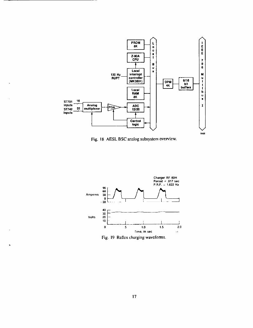
Analog Subsystem Mechanization
Figure 18 shows a simplified block diagram of the
A/D subsystcm utilized in the BSC controller. The
subsystem consists of two boards: a DATEL ST-701-
A2 16-channel intelligent A/D board and a DATEL ST-
742 32-channel expander. The ST-701 board contains
a 4-MHz Zilog Z-80A microprocessor, an 8 K PROM,
an 8 K loc',d RAM, and a 4 K static dual-port RAM
(DPR). The programmable gain amplifier (PGA) of-
fers gain steps from X1 to X128. The SBC 86/35 con-
trol and data interface to the ST-701 is through the DPR
using 8-bit and 16-bit operations.
Table 4 lists the A/D channel assignments. Chan-
nel addresses 0 through 15 select analog inputs lo-
cally multiplexed on the ST-701 board. Channels 16
through 47 are located on the ST-742 expansion board.
In order to streamline the A/D subsystcm opera-
tion, the factory-supplied firmware was removed and
a NASA-designed program consisting of a mix ofPLM80 and ASM80 modules was substituted. It
provides semiautonomous operation of the ST-701 in
several different modes through an algorithm selec-
tion routine. Control of the ST-701 is accomplished
th,'ough control flags mapped into the top of the DPR.
The mapping of these flags and various data areas
is shown in Table 5. The factory-supplied EPROM
is retained and is used during off-line subsystem
calibration.
The current waveform of the charger is a function
of both the equipment type (charger) and the servicing
task selected by the technician. The equipment type
is made known to the program by fetching a 19-byte
structure from the LSBX module RAM. This perma-
nently stored array only needs to be changed by the
technician when the charger is replaced with a different
type. The task to be performed is selected by the tech-
nician using the SCP pushbutton matrix. The program
then selects one of three algorithms: sample, burst, or
scan, depending on which is appropriate for the wave-
form. Each time the charger is powered up, the pro-
gram commands the ST-701 to do a hardware reset and
then commands it to execute the selected algorithm.
The sample algorithm is the simplest of the ST-701
modes and is used only in the open circuit task when
the waveform is direct current. In this mode, the ST-
701 services all channels round robin and places the
16-bit integer A/D values in the latest sample array.
The BSC program then asynchronously fetches the
data it needs from this array. It takes typically 2 msec
to complete a wraparound of the latest sample array.
No ampere-hour integration is perfom-ted in the sam-
ple mode.
The burst algorithm is used when the current wave-
form contains only line frequency harmonics superim-
posed on direct current. In this mode, the ST-701 ser-

viceseachchannelin turnusinga 1/60-secwindowoverwhichit takesasmanysamplesaspossible.An8-bittallyismadeofthenunlbcrofsamplestaken(usu-ally around175)andeachsampleisaddedto a24-bitsignedsum.Theresulting32-bit"burst"isplacedinaburststructureconsistingof 16arraysof48such32-bitbursts.The last frame byte indicates which is the most
recently updated array. The BSC program fetches the
data it needs from the appropriate portion of the burst
structure, and divides each 24-bit sum by its 8-bit tally
tO obtain the average value for a particular channel
over the 1/60-sec window. It takes typically 800 msec
to fill one array in the burst structure.
The scan algorithm is uscd h)r pulsed waveforms
that contain frequencies lower than line frequency.
The reflex charger waveform shown in figure 19 is
one example of such a waveform. The setpoint for the
charge operation is the plateau of the pulse; it is here
that we wish to snapshot battery current and voltages.
The scan algorithm makes this possible by providing
32 successive frames of input data, each of which con-
sists of a sample array such as that generated by the
sample algorithm. The last fi'ame byte indicates which
is the most recently filled array in the slructure, and the
ST-701 then sends an interrupt to the SBC 86/35. The
BSC program monitors battery current at each inter-
rupt and senses the descending node crossing a thresh-
old equal to 50 preccnt of the selpoint current. The
program then backs up five frames onto the plateau
and averages the preceding 16 frames. The frames oc-
cur at typically 4 msec intervals, hence, the averaging
window is approximately 64 msec.
Ampere-hour integration of battery current (chan-
nel 0) is performed in both burst and scan modes. The
ST-701 performs the integration of battery current into
a 64-bit sum while keeping track of the number of sam-
ples in a 64-bit tally counter. The BSC program sets
the integral flag to obtain a snapshot of these two quan-
tities and computes ampere-hours using elapsed timesince ST-701 reset.
The measurement of leakage current employs an au-
toranging routine in the BSC program that interfaces
to the single channel flags in the DPR. Every 15 sec,
the leakage current task wakes up and in turn checks
both the positive and negative poles of the battery. One
of the two relays is turned on, a 30-msec wait occurs
while the relay contacts close, the single channel flag
is set to channel 42, the single channel gain is set to
X1, and the single channel request flag is set to true.
The ST-701 polls the single channel request flag at in-
tervals that vary according to the algorithm, and clears
the flag when the value has been placed in the latest
sample array. The task steps the gain until the latest
sample array shows a channel-42 value of > 30 per-
cent of full scale or until gain X128 is reached. The
entire process is repeated for the other relay.
Included in the AESL BSC main command menu
is a schedule editor utility that enables the technician
to control the timing and frequency of data file cre-
ation for each of the twelve battery servicing opera-tions. The technician modifies the schedule to create
files at the beginning of the run, end of run, or both, as
well as at desired intervals throughout run.
A majority of the LSBX module's RAM is mappedinto twelve 672-bit status-save buffers. When in run
mode, a status snapshot is saved once/sec in one of
these twelve buffers. A power-fail flag is set at the
time of power failure, which at power up initiates a
BSC power fail routine to, among other things, fetch
the most recent status-save snapshot. A utility onthe AESL BSC main command menu callcd "scratch"
takes advantage of the existence of these status-save
buffers by making available for display the 12-sec
complement. Scratch allows the technician, when in
open circuit, to step back through the scatch pad onestatus file at a time.
Implementation Status
The AESL Central System has been operational as
a software production facility since November 1987.The :WI: hard disk has been formatted with a di-
rectory for 38,000 files. The integrated database tree
structure is in place, and specification and data file for-mats have been finalized.
A prototype battery station has been constructed and
final wiring harnesses are being engineered. The unit
has been operating in stand-alone mode since May
1988 and the BSC software is undergoing verifica-
tion and validation (V/V) testing. The A/D subsys-
tem firmware has been evolving as changes are in-
troduced to optimize interprocessor communications
and increase sample rates. The latest change to theA/D firmware was the introduction of the "burst" al-
gorithm to provide improved averaging for waveforms
with large amounts of line frequency harmonics. This
change proved very successful.
Considerable operational expcrience has been
gained using the iBC bubble cassette subsystem and
it has proved to be a highly reliable medium. BSC
programupdatesandspecificationfileshavebeenrou-tinelyportedfromthecentralsystemtotheprototypebatterystation.Confidencein this formof fileman-agementhaspermittedarangeofoperationsscenariosto emerge.Theoriginalconceptof datatransfersontheBITBUSwill beusedwheneverabatterystationisconnectedtothebus,buttherangeofoptionsinstand-alonemodehaswidened.Stand-aloneoperationof abatteryslationmightoccurif, forexample,anaircraftisdeployedtoanotherflighttestfacilityandabatterystationisdeployedwith it, or abatterystationmightbetcmporarilyrelocatedtothehangarto beclosertotheaircraft.Suchdeploymentsrequirethatthebatterystalionbesuppliedwith therequisitebubblecassetteshavingtheneededspecificationfiles.Oneoptionisas-signingabubblecassettetoabatterysuchthatallof itsrelatedfiles(upto amaximumof 200)areononede-vice.Thecassettescouldbehandcarriedtotheccnlralsystemandthedatafilesdumpedto :WI: wheneverdesircd.Another option is the dumping of files using
a phone line modem link through the central systemmuhiuser interface.
Following BSC program V/V, the prototype battery
station will bc turned over to BSL personnel for a 30-
day shakedown in stand-alone mode. Special empha-
sis will be given to testing the technician interface rou-
tines and to the charger wavcform analysis algorithms.
Attention will then turn to development of the BIT-
BUS software interfaces in both the central system
and the BSC. Engineering changes to the SBX 344A
arc being considered to increase the message length as
much as possible to speed file transfers. Considerable
software engineering effort is anticipated to develop
the BITBUS manager user job in the central system.
Following this, the multiuser environment will be ac-
tivated and database access utilities will be developed.
It is expected that sometime during CY88 the final
approval will be given for the fabrication of a set of
production battery stations. The presently planned ini-
tial configuration of the AESL is for a complement
of 10 battery stalions, all operating on the data bus.
The prototype battery station unit will become an en-
gineering brassboard used to evaluate new software
and support research tasks investigating new tech-
niques in battery servicing. Longer range plans for the
AESL include eventually upgrading the central system
to RMX286 with the addition of 4 Mbytes of RAM
and replacement of the SBC 544 communications con-troller with either a SBC 544A or a second SBC 548.
This enhancement will provide a better environmcnt
for the anticipated intensive multiuser operations.
Concluding Remarks
For many years the existing NASA Ames Research
Center's Dryden Flight Research Facility automated
Battery Systems Laboratory has provided a wealth of
operations experience in the servicing of aircraft bat-
teries. It will soon be replaced by the new Aerospace
Energy Systems Laboratory that will provide a mod-
ernized facility containing numerous enhancements
while retaining proven features. The new facility is
now under development and its implementation builds
on proven Multibus systems design experience gained
from other programs at Ames-Dryden. Engineering
prototype hardware has reached the testing stage, and
early results indicate that the chosen implementation
will meet the design requirements.
References
Glover, Richard D., Application Experience With
the NASA Aircraft Interrogation and Display System:
A Ground Support Equipment for Digital Flight Sys-
tems, proceedings of IEEE/AIAA 5th Digital Avion-
ics Systems Conference, Seattle, Wash., pp. 17.3.1-
17.3.10, Oct. 31-Nov. 3, 1983.
Glover, Richard D., Design and Initial Application
of the Extended Aircraft Interrogation and Display
System: Multiprocessing Ground Support Equipment
for Digital Flight Systems, NASA TM-86740, 1987.
Glover, Richard D., Concept of a Programmable
Maintenance Processor Applicable to Multiprocessing
Systems, NASA TM- 100406, 1988a.
Glover, Richard D., Aerospace Energy Systems Lab-
oratory: Requirements and Design Approach, NASATM-100423, 1988b.
Stewart, Alphonzo J., NASA Ames-Dryden Flight
Research Facility Battery Systems Laboratory, NASATM-84905, 1983.
7
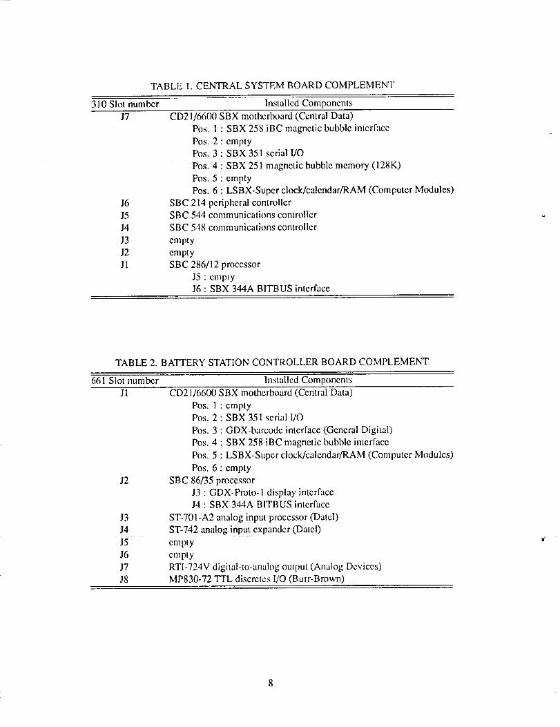
TABLE1.CENTRALSYSTEMBOARDCOMPLEMENT
310Slotnumber InstalledComponentsJ7
J6J5J4J3J2Jl
CD21/6600SBXmothcrboard(CentralData)Pos,1: SBX258iBCmagneticbubbleinterfacePos.2: emptyPos,3: SBX351serialI/OPos.4 : SBX251magneticbubblememory(128K)Pos.5: emptyPos.6: LSBX-Superclock/calendar/RAM(ComputerModules)
SBC214peripheralcontrollerSBC544communicationscontrollerSBC548communicationscontrolleremptyemptySBC286/12processor
J5: emptyJ6: SBX344ABITBUSinterface
TABLE2. BA'ITERYSTATIONCONTROLLERBOARDCOMPLEMENT
661Slotnumber InstalledComponentsJl
J2
J3J4J5J6J7J8
CD21/6600SBXmotherboard(CentralData)Pos.1: emptyPos.2 : SBX351serial1/OPos.3 : GDX-barcodeinterface(GeneralDigital)Pos.4 : SBX258iBCmagneticbubbleinterfacePos.5 : LSBX-Superclock/calendar/RAM(ComputerModules)Pos,6 : empty
SBC86/35processorJ3: GDX-Proto-1displayintcrfaceJ4: SBX344ABITBUSinterface
ST-701-A2analoginputprocessor(Datcl)ST-742analoginputexpander(Datel)empty : :cmptyRTI-724Vdigital-to-analogoutput(AnalogDevices)MP830-72TTLdiscrctcs1/O(Burr-Brown)

TABLE3. BSCTASKROSTER
Taskname Priority NotesMULTIPLEXER$TASK 019ANALOG$TASK 020BARCODE$TASK 024LSBX$TASK 030EQUIPMENT$POWER$TASK048BEEPER$TASK 050BITBUS$TASK 066BSCJOB 132BSC$1NITSTASK 150ESCAPE$TASK 155HOMESTASK 155UPSTASK 155DOWN$TASK 155TAB$TASK 155TEMP$PROBES$TASK 201LEAKAGE$TASK 202SYNCH$TASK 210MASTER$DISPLAY$TASK 220PRINTER$POLLSTASK 225PRINTER$TASK 230SUPERVISOR$TASK 240DISPLAYSMODE$TASK 245CRTSMENUSTASK 250
ScansSCPpushbuttons& LEDsInterruptlevel0010hInterruptlevel0012hInterruptlevel0015hControlspowerrelaysControlsSCPbeeperInterruptlevel0038hUserjobCreatedbyBSCJOBSetsESCAPEflagSctsHOMEflagSetsUPflagSetsDOWNflagSetsTAB flagReadstemperatureprobesMeasuresbatterycaseleakagecurrentSynchronizesdataacquisition& displayControlsSCPdisplaySamplesprinteron-linestatusControlsprinterhardcopy(cntlP)ControlsoperationsequencingSamplesdisplayselectpushbuttonsManagesterminalinterfaces

TABLE4. ANALOGTODIGITALCONVERTERCHANNELASSIGNMENTS
Channel Assigmmen! Channel AssignmentO0 Charger amps 24 Cell 14 w)lts
Ol Load bank amps 25 Cell 15 volts02 Load bank volts 26 Cell 16 volts
03 Load bank deg 27 Cell 17 volts
04 Spare 28 Cell 18 volts
05 Spare 29 Cell 19 volts
06 Spare 30 Cell 20 volts
07 Spare 31 Cell 21 volts
08 Spare 32 Ccll 22 volts
09 Spare 33 Cell 23 volts
10 Spare 34 Cell 24 volts11 Cell 01 volts 35 Cell 25 volts
12 Cell 02 volts 36 Cell 26 volts
13 Cell 03 vohs 37 Cell 27 volts
14 Cell 04 volts 38 Cell 28 volts
15 Cell 05 volts 39 Cell 29 volts
16 Cell 06 volts 40 Cell 30 volts
17 Cell 07 volts 41 Battery volts
18 Cell 08 volts 42 Leakage milliamps
19 Cell 09 volts 43 Top tcmp
20 Cell 10 volts 44 Case tcmp #1
21 Cell 11 volts 45 Case temp #2
22 Cell 12 volts 46 Case tcmp #3
23 Cell 13 volts 47 Case tcmp #4
TABLE 5. ST-701 DUAL-PORT RAM MAPPING
Address Function
8FFFH
8FOFH
8FOEtt
8FOCtt
8FOBtl
8FOAIt
8F04H
8F03H
8F01H
8F00H
8EF8H-SEFFH
8EFOH-SEF7H
8E90H-8EEFH
8000H-SESFH
Interrupt doorbellRun mode talkback
Run mode command
Single channel request
Single channel gain
Single channel number
120-Hz clock flag
Integral fetch flagLast frame num[x_r
Algorithm number
Integral sum (64-bit long integer)
Integral number iterations (64-bit counter)
Latest value array (48 integers)
Data output structures area (alternate overlays)
10
I Tandyservicing records
archive
Printer
hardcopycabinet
_User terminal J
Computerarea
I System terminal I I Lineprinter I
, J..... , In .........
I HP-IO00 System ..... -t-
-- "_ Central Computer
Setup " + Data
W .......
I .n_,o_Oata IO.er,e.mi°a,IAcquisition System
I Position 2 I
Fig. 1 Battery Systems Laboratory overview.
Servicing Iarea User terminal
2,fI Position 1 I o,'tion'OI
Battery 1station
#1
I Centralsystem
1
I 2.4 MHz serial data bos
s';_o°|/ s":_°njFig. 2 AESL ovcrvicw.
220-Vpower
T
2.4 MHz serial data bus
Controllersubsystem
Monitor
plate
Battery
Temp.probes
Fig. 3 AESL battery station overview.
11= _

Charger ..... ...............
SOP '::::::
Fig. 4 Battery station bench.
Userterminals
Printer .,,-----
i m
C Polling message B S JE S ,,Time/date A T I
Y b T A IN S Data base filesT ,, TT I
TR E 4 Real-time status E I IA Servicing records R O IL M =
Bamodewand
Status/controlpanel
Audible
Y N I alarm-
Fig. 5 AESL functional overview.
V
12 BLAC_L
ORIGINAL PAGE
AND W_TE pI-IOII_3RAPH

I Database [
• ! ! e ! e
Ik -(
" " " * Call specification files
M )Y
Data files
luele
A± ±Y
Load profile files
8467
Fig. 6 Integrated database tree structure.
FILE-CSPEC; CSPEC-14H220; CTYPE-NiCd; _HRATED_tO.O/
HXCHGV-I._; HXDIFFV-0.25; HX_OPV-O.O3J HXCPIQT-115;
SETRFL_=14.0I [NDRFLPII.0J
SETPULr-14._I
SET2MCZ-tO.OJ SET2TC_-5.O! SET_OC_-2,S) ENDCXU-t.59;
$LCTCUIimt.70; SETCU_-IO.OI [NDCU_-O, IOI
UENTPSZa2,0 _O tO,O¿ CASEPSZ-IO.O; TOROUE-20,O1
Fig. 7 Example cell specification file.
HXAHm14
8481
F|LEIBATTDATAB BRTTDATA'BE0817140007; BRTTSP[C-1234S678_ STATION=27J
TASK=CaplciL_ Testl OPERATOR-Oan Smithl
PROJ£CT=TESTJ HOOELNO-CA-5-20J AHRATED-30.OW NUHCELLS-20J
£OUZP-Christie Refllxl STATUS-End of Punt PERIOD-J
_ATTVOLTS-22.193J DATTAHPS--29.6851 ELAPTZHE-Ols20:48; AH--38.129;
TENPg-91.281,98.896,94.251,96.788,96.3651
LEAK&OIE-O.4_-O.404J
CELLUOLTg-LI4,1.13,Lt2,1,11tI.15tI.09PI.Og,I.12,1-O9_I.12,1.12wI.13'
1.10Jl.13n1.13,1,10,1.14,0.99r1.10_1.08;
CAUTRARNsCIII 1g minllHJ_ vol_s;
848O
Fig. 8 Example battery servicing data file.
13

EC88 0168-003
Fig. 9 Central system console.
BO IR0SBX258 : :IR1
SBX351 RxRDY IR._..2
SBX251 :BI: IR..._3IR4
m
IR..__$IR6
SBX3Sl TxROY IR_.7
m._._oIR1
IR2m
IR3
SBX344 BITBUS IR4IR_SSIR6
Line printer IR._.7
Fig. 10
8259APIC
slaveon
CD2116600
8259APIC
slaveon
SBC286112
10 MS clock IFIOIR1
SBD rupt I'_
SBC544 1113
$BC,548 IR4
SBC214 1115
8274 serial 11:16IR7
8259APIC
masteron
SBC286112
Central system interrupt configuration.
Not used
Fig. 11
EC88 0168-002
Battery station controller subsystem chassis.
14 ORIGINAL PAGE
BLACK AND WHITE PHOTOGRAPH
ORTGINALPAGEBLACK AND WHITE PHOTOGRAPH
48 analogs
AID subsystem
2.4 MHz serlal data bus
Pedpherals q
I
1o, -iio,°1t t
72 dlscretes 0.10 VOC
C.P.U.
:1Bubble
memory
rPowerrelays
control1
I
Fig. 12 BSC overview. Fig. 13
EC88 0168-004
BSC cardcage.
NDP MINT
10MS clock
SBX344 BITBUS
Line printer
8251 TxRDY
8251 RxRDY
IR0 I
IR2i
IR3
IR4
IR5
|R6
IR7
8259APIC
masteron
SBC 86135
AC NMIlow_
INTR 8086 ICPU I
w
ST701 AID
SBX3F.1 RxRDY
OOX.Barcode
SBX258 :Be
LSBX 1 Hz
$BX258 :BI:
SBX3S1 TxRDY
IR0
IR1
IR2
IR3
IR4
IR5
IR6
IR7
8259APIC
slaveon
CD2116600
Fig. 14 BSC interrupt configuration.
8472
15

FFFFF
E0000
DAC07
DAC00
81FFF
800OO
Memoryaddress
00000
27256 EPROMS
128K
DAC board 8 Bytes
AID RAM 8K
SBC86135
RAM
512K
Fig. 15
EPROM mapping:
FFFS0.FFFFF RestartFE300-FFFTF Bootstrap
F8240-FE2FF SDM monitor
F0000- F823F Nucleus
E0000-EFFFF Basic IIO
PSBC 80135 RAM mapping:
40000.7FFFF User Job3E000-3FFFF Bootstrap data
01100-3FFFF Root job andRMX86 data
010S0.010FF BIOS data01040-0104F Nucleus data
O0400.00FFF SDM data
00000-003FF Vectors
BSC memory mapping.
8473
SBC 86135 Leakage relay box Battery
processor undertest
Status
register + 12 + 12
2
S ., I_, ., I<_ 1-amp7 I I _ q _ fuses
i • i
I soQsow I -"_-_ I
To AID8470
Fig. 16 Leakage relays control.
SBC 86135
processorI
8253 I
PiT I• +s_--
GO 0L74 L II l _+-_[r-'-------I
Ol
-
0 U 115V
' ' ++ 60Hz2 13 I Timer 1
4 1
5 1 " Mode I
6 I " Binary- , , Max counts
• 0.42 sac
Fig. 17 Power relay control interface.
Power control box
220V powerA
rbTJ LTJ ' :"
'+ i---;?....... jI
_hird
relay (if 30)
8471
1
16
ST701
inputs
ST742
inputs
8K /i,;¢
_BU
120 HZ i ptRUPT controller
| 1MK38011 |
16
multiplexer' [_ ; ii;_l_t I
,,)
Fig. 18 AESL BSC analog subsystem overview.
/N
IE
EE
79
6
M
uI
tIb
U
s
v8468
Amperes
Volts
6O
3O0
- 30
Charger RF-80HPeriod = .617 secP.R.F. = 1.622 Hz
4O
2O
10 I I 1 J0 .5 1.0 1.5
Time, in sec
Fig. 19 Reflex charging waveforms.
2.0
17

hlj_ Ae_r_u_s andReport Documentation Page
1. Report No.
NASA TM-101706
4. Title and' Subtitle
2. Government Accession No.
The Aerospace Energy Systems Laboratory:
Hardware and Software Implementation
7. Author(s)
Richard D. Glover and Nora O'Neill-Rood
9. Performing Organization Name end Addrm
NASA Ames Research Center
Dryden Flight Research Facility
P.O. Box 273, Edwards, CA 93523-5000
12. Sponsoring Agency Neme end Addrese
National Aeronautics and Space Administration
Washington, DC 20546
3. Recipient's Catalog No':
5. Report Date
July 1989
6. Performing Organizatkm Code
8. Performing Organization Report No.
H-1518
10. Work Unit No.
RTOP 533-02-51
11. Contract or Grant No.
13. Type of Report and Period Covered
Technical Memorandum
14. Sponsoring Agency Code
15. Supplementary Notes
Prepared as conference paper for presentation at iRUG 5th International Conference, Schaumberg, Illinois,
November 14-15, 1988.
18: Abstract
For many years NASA Ames Rcsearch Center, Dryden Flight Research Facility has employed automation in
the servicing of flight-critical aircraft batteries. Recently a major upgrade to Dryden's computerized Battery
Systems Laboratory was initiated to incorporate distributed processing and a centralized database. The
new facility, called the Aerospace Energy Systems Laboratory (AESL), is being mechanized with iAPX86
and iAPX286 hardware running iRMX86. This paper describes the hardware configuration and softwarestructure for the AESL.
17. Key Words (Suggested by Author(s))
Computerized battery _rvicing
Distributed processing
Muhibus
19. Security'Classif. (of this report)
Unclassified
18. Distribution Statement
Unclassified -- Unlimited
20. Security Clas=If. (of this page)
Unclassified
Subject category 61
21, No'. of pages 22. Price
20 A02
i , i,
NASA FORM 1626 OCT
*For sale by the National Technical Information Service, Springfield, VA 22161-2171.