the 46th hatfield memorial lecture at sheffield university/file/46th... · the 46th hatfield...
TRANSCRIPT

p&e1198.ppt
Power
and the
EnvironmentP C Ruffles FRS, FEngDirector of Engineeringand Technology, Rolls-Royce plc
The 46th Hatfield Memorial Lecture
at Sheffield University

p&e1198.ppt
Rolls-Royce power
Rolls-Royce provides
power systems for air,
sea and land-based
applications
Gas turbines are our
principle power
generating products
Industrial Aerospace
23% 77%

p&e1198.ppt
Power — Environmental impact
The impact of economic activityon the environment is a majorconcern facing the worldcommunity
Our products convert energy infossil fuels to thrust ormechanical power and emit theircombustion products to theatmosphere
Noise and emissions of NOx,SO2, UHCs and CO at groundlevel are of concern to localcommunities
NOx & SO2 can cause acid rain
CO2 & NOx may effect globalwarming and deplete the ozonelayer

p&e1198.ppt
Aerospace power — Noise
No bypass duct
Low bypass ratio
High bypass ratio
Avon
Conway
Spey
RB211-535 Tay
V2500-524G/H
Trent
1960 1970 1980 1990 2000Entry into service
75%
reduction
Total aircraft noise - Rolls-Royce engines
Low bypass ratio High bypass ratio
Compressor
Turbine & core Turbine & core
Compressor
Fan
Jet
Shock & jet
Engine noise sources
Communities local to airports
are worst affected due to take
off and landing manoeuvres
International and local
regulation impose very
stringent limits
Reductions in aircraft noise
are largely offset by
increased traffic and aircraft
size
Future aircraft must therefore
become even quieter

p&e1198.ppt
Aerospace power — Noise
Noise is controlled by:
Choice of bypass ratio (BPR)
Space between rotating parts
Number and shape of blades
Acoustic lining in inlet & exhaust
Integrated exhaust streams or
advanced nozzles
Component aerodynamics Blade number selection
Mixed-flow exhaust (BPR <6)
Separate jets (BPR >6)
Wide-chord fan
Increased bypass ratio Acoustic liners

p&e1198.ppt
Aerospace power — Noise
In the past, satisfying noise,
fuel burn and range targets
have not been in conflict
However, with current
technology the economic
optimum BPR is around 6
Latest engines (Trent 500)
have higher BPR to reduce
noise
Noise technology must focus
on reducing sources without
compromise to fuel burnBypass ratio3 6 9 12 15
Trent 500Trent 900
Economicoptimum
Fuel burn
Aircraftweight
Operatingcosts
Noise

p&e1198.ppt
Gaseous emissions — Aerospace & energy
Power stations emit UHCs,
CO, CO2, NOx & SO2
Airports are source of emissions,
notably UHCs, CO, CO2, NOx
& smoke
Ground
Acid rain& smog
1km
Ozone
CO2 reflects IR back to earth.
NOx acts as catalyst to
create ozone which reflects
IR back to earth
Global warningAircraft at cruise emit CO2 & NOx
Stratosphere (~20km)

p&e1198.ppt
Gaseous emissions — Environmental impact
Air traffic contributes ~3% of global
CO2 and ~1% of NOx emissions
no significant SO2 emission due to
clean, non-sulphur containing fuel
Air traffic is expected to increase by
5% per annum over next 20 years
future contribution could be ~7% CO2
& ~2% NOx respectively
Power generation produces large
amounts of CO2 (29%), NOx (21%)
and SO2 (58%)
— near term: gas turbines will reduce
emissions due to cleaner fuel and
combustion, and better efficiency
— longer term: more advanced means
of energy conversion are required
Carbon dioxide (CO2)
Nitrogen oxides (NOx)
Sulphur dioxide (SO2)
Waste treatment
Power stations
Industry
Domestic
Other
Road traffic
Agriculture
Other mobile
Solvents
Nature
% of man-made sources - 1995

p&e1198.ppt
Aerospace power — Emissions legislation
Legislation is focused on the
landing/take-off cycle and limit
UHCs, CO and NOx— local impact often provokes
localised legislation
— modern engines have
acceptable UHC, CO and
smoke emission
— future legislation (2002)
requires a 36% reduction of
NOx relative to 1986 limit
(16% at 1996 limit)
More advanced cycles improve
CO2 (fuel burn) but deteriorate
NOx
Current effort is focused on
reducing NOx and CO2
emissions
COHC NOxSmoke
1970-73
1979-83
1985-88
2000
Averageemissions
PredictedNOx
200
100
20
40
Emissions - gm/passenger
SAE smokenumber
1960-70
1980-90

p&e1198.ppt
Aerospace power — Emissions constraints
Primary
zone
Secondary
zone
At idle:Combustor pressure andtemperature are low, andprimary zone is weak
— inhibits chemical reactionwhich creates CO and UHCs
At high power:Combustor temperature andpressure are high and primaryzone is rich
a fuel-rich mixture createssmoke which is burned offby secondary combustionsecondary combustioncreates NOx establishing atrade with smoke
Good compromise is achievedthrough aerodynamic andmechanical design
NOx & smoke reaction rate
10 20 30 40 50
Fuel/air ratio
+ve
-ve
Smoke
NOx
Decreasing temperature
Strutless
pre-diffuser
Cowled head to
ensure full pressure
feed to backplate
Large airspray injectors
for improved mixing
and smoke control
Large primary zone
volume for altitude
re-light
Small total
volume for
NOx control
Lipped cooling rings
for mechanical
durability
Deep annuli for good
aerodynamic feed
to mixing holes

p&e1198.ppt
Aerospace power — Combustion technology
Double annular combustors allow
‘staged’ combustion to optimise
idle and max.power
— pilot chamber operates with
good idle and altitude relight
characteristics
— main chamber is fed with fuel
progressively as thrust increases
Pre-mixed injectors can eliminate
NOx emission by thorough mixing
of air with fuel prior to combustion
— oxygenated mixture gives a more
stable, lower peak temperature
(~2000K)
— NOx is first produced ~2100KPre-mixed double-annular combustor
Pilot
Main
Double-annular combustor (BRR715)
Pilot
Main
p&e1198.ppt
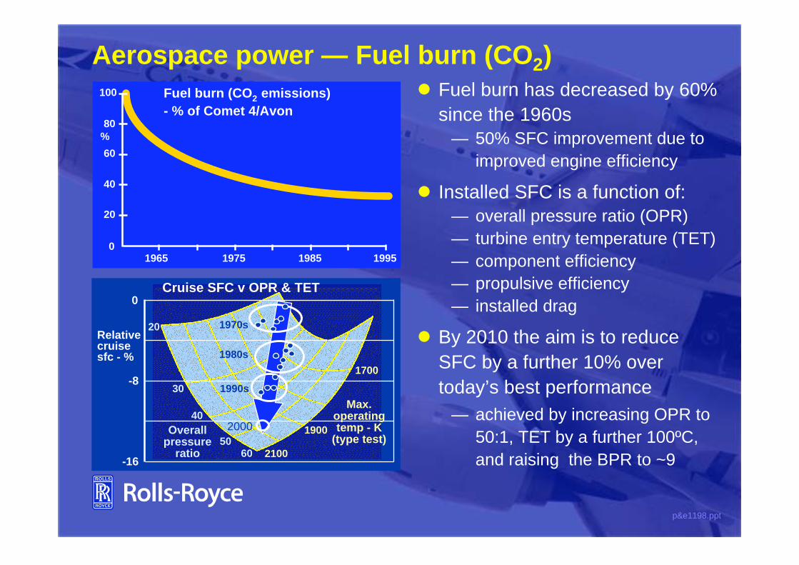
Aerospace power — Fuel burn (CO2)
Fuel burn (CO2 emissions)
- % of Comet 4/Avon
1985 199519751965
80
60
40
20
0
%
100 Fuel burn has decreased by 60%
since the 1960s
— 50% SFC improvement due to
improved engine efficiency
Installed SFC is a function of:
— overall pressure ratio (OPR)
— turbine entry temperature (TET)
— component efficiency
— propulsive efficiency
— installed drag
By 2010 the aim is to reduce
SFC by a further 10% over
today’s best performance
— achieved by increasing OPR to
50:1, TET by a further 100ºC,
and raising the BPR to ~9-16
-8
0
Relative cruise sfc - %
40
5060
30
20
2100
1700
1900
Max.operatingtemp - K
(type test)Overall
pressureratio
1970s
1980s
1990s
2000
Cruise SFC v OPR & TET

p&e1198.ppt
Aerospace power — Turbine temperaturesTET has increased by 300°C
during last 25 years
— 150°C due to improved cooling
design (200°C above melting
point of HP turbine blade
material)
— 150°C due to improved
material and casting technique
(component efficiency
improves with minimum use of
cooling air)
— blade life has doubled over this
period
HP turbine blades require
compressor bled cooling, but
three-shaft engines allow IP
blades to operate uncooled at
1000°C
Type test temperatures of RB211 & Trent HP
turbine blades
TET
ºC
Equiaxed MarM002Directionally-solidified MarM002Single-crystal CMSX-4
B
B2 B4
D4
C2-524G
E4
-524H
T775 T890
T895
T772
1975 2000
1300
1600
HPT IPTGeneral layout ofengine core

p&e1198.ppt
Aerospace power — Turbine materials
Turbine blades have evolved to cope
with increases in TET
wrought Nimonic alloys
equiaxed MarM002
directionally-solidified MarM002
single-crystal superalloys (SRR99,
CMSX-4, RR3000/3010)
Material grain boundaries are a
source of weakness
— directional solidification removes
boundaries which are perpendicular
to strain
— single-crystal growth removes all
grain boundaries and leads to
secondary benefits
DS MarM002
CMSX-4
RR 3010
0
40
80
120
Material temp. increase (°C)
Improvements in
material creep
property
Equiaxed MarM002 baseline

p&e1198.ppt
Aerospace power — The future
The ‘flying wing’ offers
significantly-reduced drag for
high-capacity aircraft
Contra-rotating aft fan concept
can be over-wing mounted and
improves SFC, weight and noise
Pre-mixed, double-annular
combustors will offer reduced
emissions
All-electric aircraft offer future
improvements in fuel burn and
operating cost
Flying wing
Aft-fan
Innovative aircraft and engine designs are required to provide step
improvement in performance

p&e1198.ppt
Industrial power
Rolls-Royce also supplies
power generating products
for the following markets:— small and medium sized
power stations (up to 100
mW)
— oil and gas pipeline pumping
— marine propulsion
Our principle products in
these sectors are:— aero-derivative gas turbines
(3 to 65mW)
— medium size diesel engines
(0.3 to 15mW)
Oil & gas pumping
Marine propulsion
Power
generation

p&e1198.ppt
Industrial power — Gas turbines
Industrial legislation is controlled
locally and is more stringent than
aerospace
Gas turbines offer small/medium
industrial power with distinct
environmental advantages:— they are compact and offer good
efficiency
— they are readily available to
provide power in a distributed
system
— specially-designed combustion
system for low Nox (29ppm
compared with aero 300ppm)
— industrial engines burn cleaner,natural gas rather than kerosene
Industrial Trent is most powerful
and efficient gas turbine of its kind
Aero Trent
New
compressor LP bleed
Dry Low Emissions
combustor LP turbine
& exhaust
redesign
Rear drive
added
Industrial Trent installation

p&e1198.ppt
Industrial power — Trent DLE combustor
Conventional combustion
at low powers for stability
Reverse-flow design
allows easy
maintenance of fuel
injector and combustor
Increased residence
time to control CO
8 combustors designed
for dual fuel operation
Uniform pre-mixed
lean-burn combustion
zones giving uniform
low temperatures
and hence low NOx
Series staging to allow
operational flexibility
with low emissions
over power and
ambient temperature
range
p&e1198.ppt
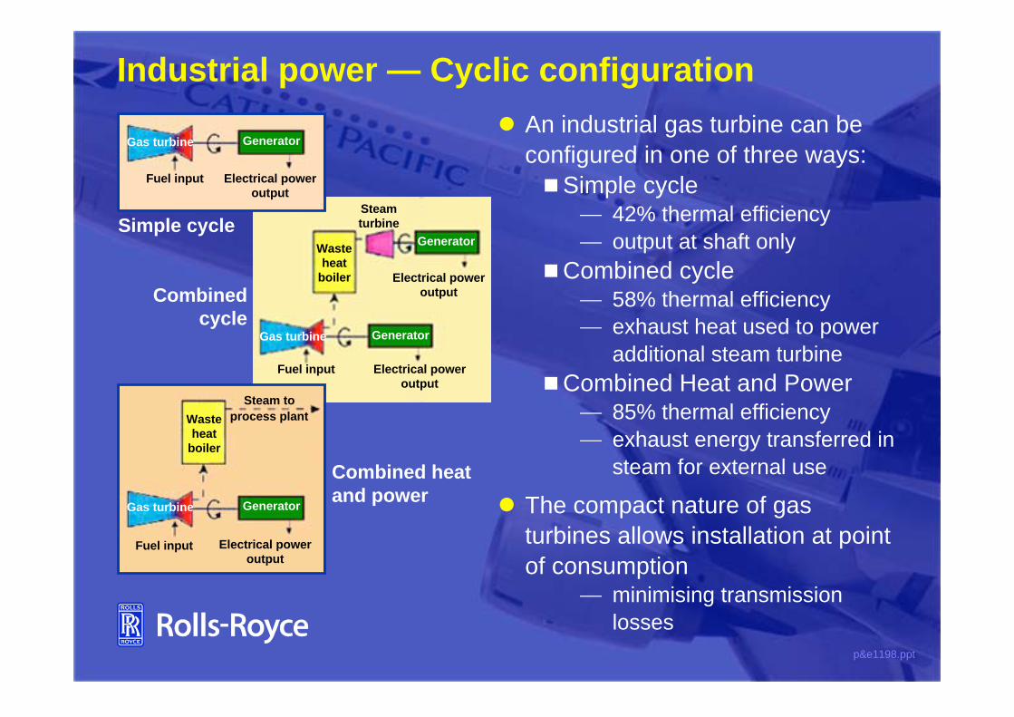
Industrial power — Cyclic configuration
Combined
cycle
Waste
heat
boiler
Generator
GeneratorGas turbine
Steam
turbine
Electrical power
output
Electrical power
output
Fuel input
An industrial gas turbine can be
configured in one of three ways:
Simple cycle42% thermal efficiency
output at shaft only
Combined cycle58% thermal efficiency
exhaust heat used to power
additional steam turbine
Combined Heat and Power85% thermal efficiency
exhaust energy transferred in
steam for external use
The compact nature of gas
turbines allows installation at point
of consumptionminimising transmission
losses
Combined heat
and powerGeneratorGas turbine
Waste
heat
boiler
Fuel input Electrical power
output
Steam to
process plant
Simple cycle
GeneratorGas turbine
Fuel input Electrical power
output

p&e1198.ppt
Industrial power — Diesel engines
Allen Power Engineering produce
large diesel engines for industrial
and marine use
The recently-launched Allen 5000
is the most efficient (45%) and
powerful diesel engine of its
capacity (500kW per cylinder)
— diesel engines offer the ability to
burn low cost, low grade fuel
— electronic variable fuel injection
enables each cylinder to be
optimised for SFC and emissions
under all conditions

p&e1198.ppt
Industrial power — Fuel cells
Emissions
Conventionalpower station
Experimentalfuel cell
Coal Coal Gas
SO2
NOx
Gas
30
20
10
Combined cyclelocal station
Fuel
Air C T ~
x__
Combinedcycle
schematic
Fuel cells are an emerging future
technology for fossil-fuelled power
stations— they convert fuel energy directly
into electrical power by oxidation
of the fuel
— efficiency of ~70% in combined
cycle, giving significant CO2
reduction
— Nox and SO2 output <1vppm
A fuel cell consists of an ion-
conducting electrolyte between two
porous electrodes— electrolyte separates fuel (anode)
and air (cathode) and mediates
the reaction
— electrons migrate from anode to
cathode, causing an oxygen ion to
migrate through the electrolyte

p&e1198.ppt
Industrial power — Distributed systems
Traditional centralised energy supply is being supplemented by
localised stations
Technology has improved
efficiency of smaller
generators
De-regulation of industry
has removed barriers to
entry
Transmission losses are
minimised
Improved system efficiency
leads to lower cost and
environmental damage
Conventional
supply
Renewables
Fuel
cells
Gas turbinesDemand
Heat to process
plant

p&e1198.ppt
Rolls-Royce power — Summary
Aero engines have reduced emissions and noise dramatically
over the last 25 years
Similar improvements in the future will require modification to
both the engine and the airframe
Gas turbines in simple cycle, combined cycle and CHP
configurations are ideally suited to reduce CO2 and NOx relative
to coal burning power stations
Aero derivative gas turbines are quick to erect and can be
installed at point of energy consumption
Future developments embrace more advanced gas turbine
cycles, fuel cells and other energy converters in a distributed
system

p&e1198.ppt
Power
and the
EnvironmentP C Ruffles FRS, FEngDirector of Engineeringand Technology, Rolls-Royce plc
The 46th Hatfield Memorial Lecture
at Sheffield University