the 32t - mit haystack observatory baseline ~350 m ... upgrades to firmware functionality over time...
TRANSCRIPT

The 32T

The Approach to 32TA necessary development phase in getting to the 512TAn engineering test-bed
Check out the hardware & firmware (+ software) performanceIron out the interfaces and system integration aspectsGet field experience Learn more about the operating environment, sky, ionosphere, ...An opportunity for things we did not think about to crop upHone our deployment skills and procedures
We have a tight schedule for the MWA ⇒ the 32T must follow a tight schedule as well
Forces one to focus on the key functionality (avoids feature creep)
The implementation plan follows a phased approachExpected hardware availability schedule Expected infra-structure availability scheduleMaximise the learning/returns from the effortCommon sense

Some Guiding PrinciplesMaximise environmental exposure to
hardwareTest, debug and verify all interfaces in lab
prior to field installationExercise the system enough to learn from
it and for strains and cracks to show upIdentify key questions and conduct
focused observing campaignsLearn in time to feed into the MWA
development process

32T Specs32 tiles, 4 nodes Collecting area ~550 m2 (~1 VLA dish, 6.25% of full array)Bandwidth – 32 MHz∆t = 62.5 ms ∆ν = 80 kHzlongest baseline ~350 m (~15’ @ 200 MHz)496 physical baselines (0.4% of full array)Max data rate ~12.7 Mvis/s (UVFITS ~100 MBytes/s)Power consumption ~10 kW (includes HVAC in Control Facility)

32T Configuration
Randomised Reuleauxtriangle
Well sampled, reasonably uniform uv coverage
Tile spacings along the arm vary in a log mannerLongest baseline ~350mDistance between vertices 200mOptimisation in progress
m
m
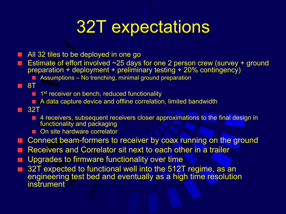
32T expectationsAll 32 tiles to be deployed in one goEstimate of effort involved ~25 days for one 2 person crew (survey + ground preparation + deployment + preliminary testing + 20% contingency)
Assumptions – No trenching, minimal ground preparation8T
1st receiver on bench, reduced functionalityA data capture device and offline correlation, limited bandwidth
32T 4 receivers, subsequent receivers closer approximations to the final design in functionality and packagingOn site hardware correlator
Connect beam-formers to receiver by coax running on the ground Receivers and Correlator sit next to each other in a trailerUpgrades to firmware functionality over time32T expected to functional well into the 512T regime, as an engineering test bed and eventually as a high time resolution instrument

Infrastructure requirements
Lab and office space (trailer?)Living space (mobile home, donga?)Power generation and fuel supplyInternet connection to the outside world

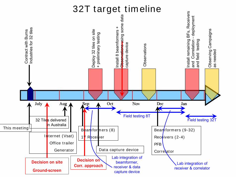
32T target timeline
This meeting
Con
tract
with
Bur
ns
Indu
strie
s fo
r 32
tiles
Dep
loy
32 ti
les
on s
ite
+ pr
elim
inar
y te
stin
g
Obs
ervi
ng C
ampa
ign
Obs
ervi
ng C
ampa
igns
as
nee
ded
Fiel
d in
tegr
atio
n an
d te
stin
g
Beamformers (8)
1st Receiver
32 Tiles delivered in Australia
Field testing 8TField testing 32T
Beamformers (9-32)
Receivers (2-4)
PFB
Correlator
O asbs
ervi
ng C
ampa
igns
n
eede
d
Dep
loym
ent
and
field
tes
ting
Decision on site
Ground-screen
Decision on Corr. approach
Data capture device
Internet (Vsat)
Office tralier
Generator
Lab integration of beamformer,
receiver & data capture device
Lab integration of receiver & correlator
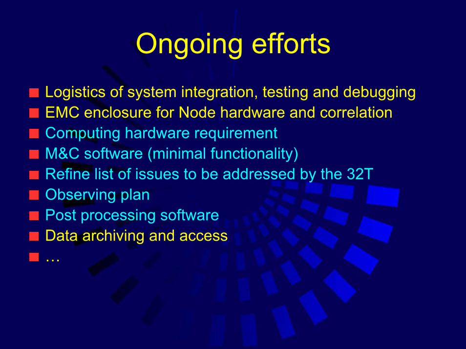
Ongoing effortsLogistics of system integration, testing and debuggingEMC enclosure for Node hardware and correlationComputing hardware requirementM&C software (minimal functionality)Refine list of issues to be addressed by the 32TObserving planPost processing software Data archiving and access…

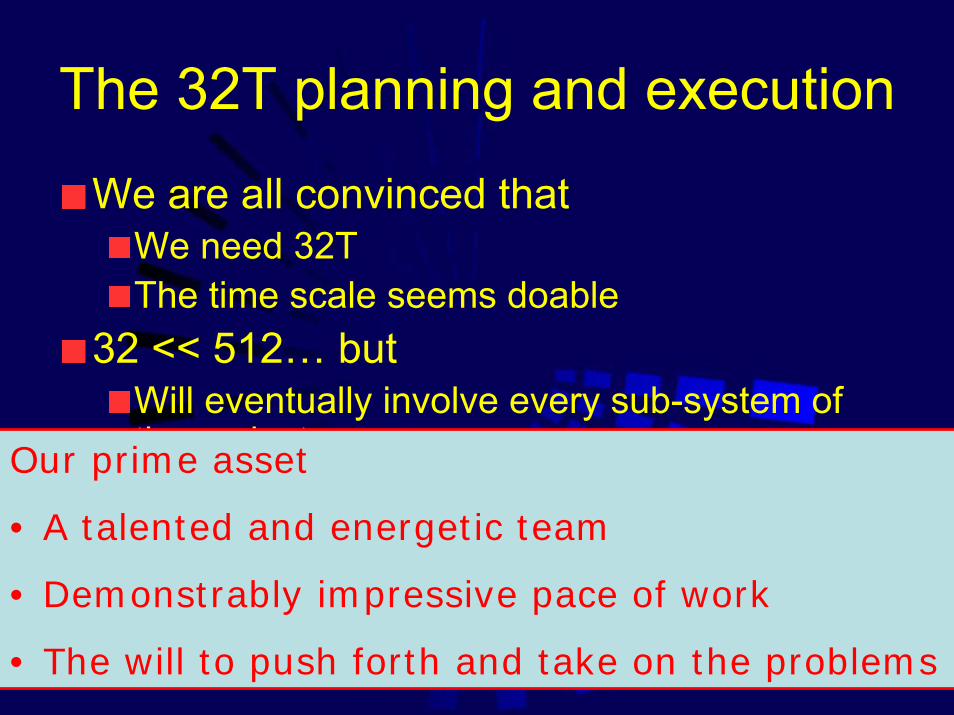
The 32T planning and execution
We are all convinced that We need 32T The time scale seems doable
32 << 512… butWill eventually involve every sub-system of the projectLarge task, involves the entire teamIt is a chain of events which don’t commuteTight timeline
Our prime asset
• A talented and energetic team
• Demonstrably impressive pace of work
• The will to push forth and take on the problems

My role
CoordinatorProvide a skeleton implementation plan, seek inputs from appropriate people to flesh outKeep a system wide perspective on the state of thingsLook out for problems, schedule impacts, inconsistencies and gaps in planningOrganisational glue, communcations, …
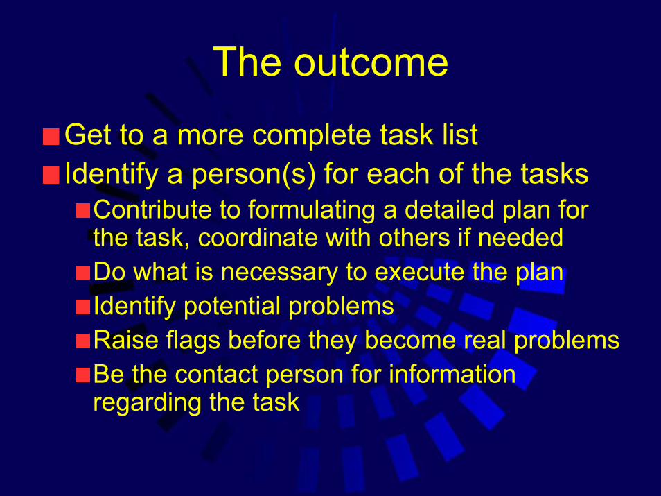
The outcome
Get to a more complete task listIdentify a person(s) for each of the tasks
Contribute to formulating a detailed plan for the task, coordinate with others if neededDo what is necessary to execute the planIdentify potential problemsRaise flags before they become real problemsBe the contact person for information regarding the task

Site
Identifying the land on which MWA will appearPermissions Initial survey of potential sites – Merv, 07/16/07
First survey of the circular regions in Tony’s polygon + perhaps another region
Coordination with ATNF about locations of ASKAP, MWA and central building – Boolardy Site Coordination Group
Infrastructure sharing (common building, power generation, optical fiber pipe out of Boolardy,…)

Infrastructure
Compile a list of requirements (accommodation, lab/office space, power requirements) and time scale – Bob SaultCommunicate/coordinate with ATNFIdentify concerns, looks for solutions/work arounds – Bob Sault

Tile
Dipoles – Brian CoreyGround-screens – Brian/Merv/Steve Burns
Identify suppliers, lead times, …Beam-formers – Brian CoreyCables (co-ax+power) – Brian/Mark WatersonPower generation – ED Protection against fauna - Brian

DeploymentExpedition 1 Goals
Deploy as many of the 32 tiles as possible (ground planes + dipoles + lay (few) co-ax cables)Test as many of the tiles as possible
2 beam-formers, 1 spectrometer available, set up overnight drift scans 1 tile at a timeTimeframe – 3rd-4th wk. AugEstimate volume of work ⇒ size of team, duration of stay (4 people, ~2 wks)Identify the team
Team leader (someone with prior site experience) – Brian/DivyaOne technical expert Skill set – task listSpecial skills (first aid certification, survey, drivers)Team leader to assign responsibilities of local logistics to team members and othersStudents from (MKI)Mark Derome (Haystack)

Deployment…Equipment list - David Barnes?/Team Leader
ProcurementInstallation procedure
Tile assemblyHow do we make sure that we learn from this
Test procedure(s)OHS issues -Cultural Sensitivity training (9-15 July) – Bob SaultConfiguration -Divya Oberoi

Deployment…
Trenching?

Receiver
Mark WatersonDevelopment Milestones ?Raise flags when you have concerns, before they become problems

Data Capture (8T)/Correlator
Discussions underway - RogerDecisions made?
Decision point – availability of the PFB?Early SepLeave enough time to pursue alternative approaches
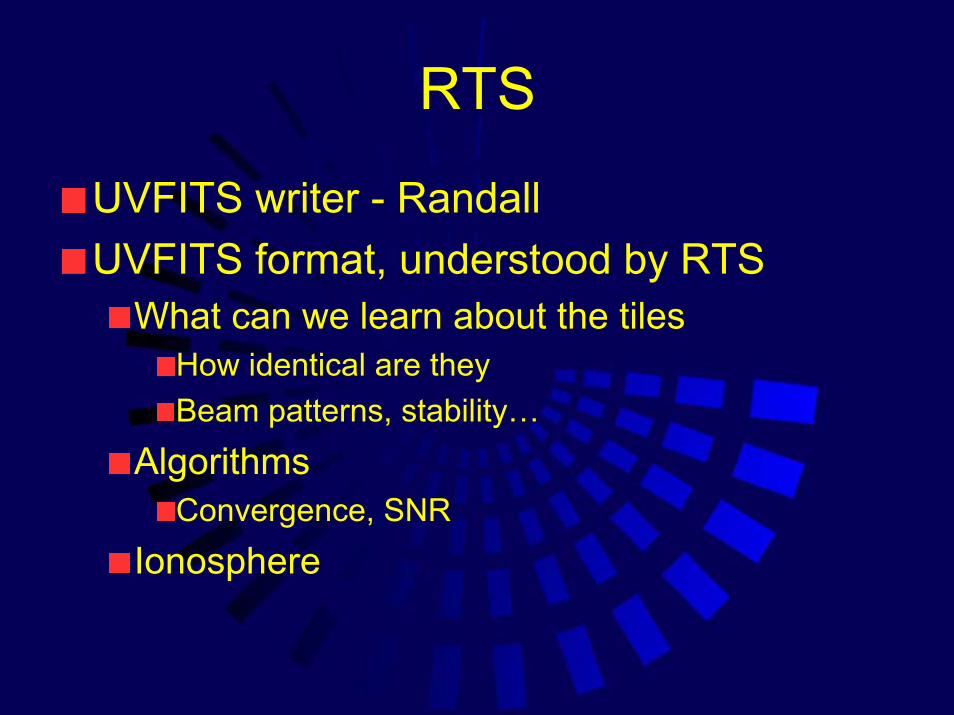
RTS
UVFITS writer - RandallUVFITS format, understood by RTS
What can we learn about the tilesHow identical are theyBeam patterns, stability…
AlgorithmsConvergence, SNR
Ionosphere

EMC Enclosure for – Roger/AntReceiverCorrelator Field installable Faraday rooms -
Computing hardware requirementSystem integration (Lab/Field) - Roger
Tiles – Beamformer Beamformer – ReceiverReceiver – Data capture deviceReceiver – Correlation

M&C
Control – Lister/MiguelHardware status and system healthSimple data checks - Randall
Near real time display – matrix of mean,rms of amp, ph on different baselines
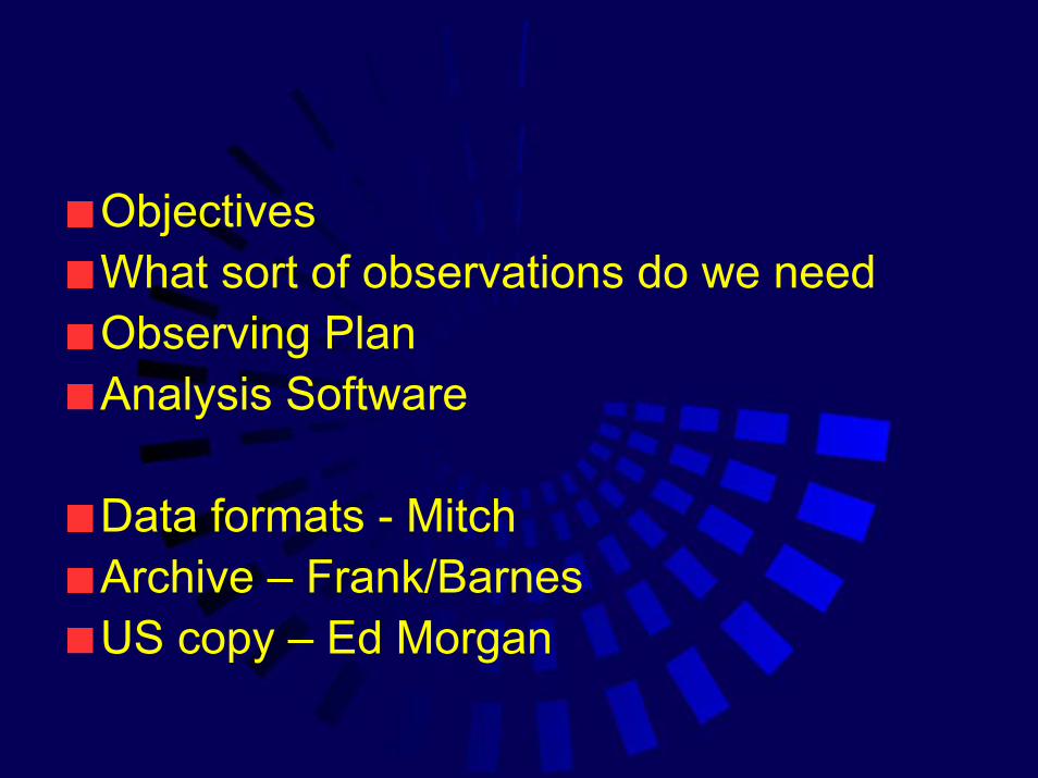
ObjectivesWhat sort of observations do we needObserving PlanAnalysis Software
Data formats - MitchArchive – Frank/BarnesUS copy – Ed Morgan

1st Expedition
7th Sept, 2 wk7 peopleDeploy 32 tiles2 ‘old’ beamformers + Acquarisspectrometer
Brian, Divya, Mark Derome, Steve Burns, Merv, Dave Herne, Chris

2nd Expedition
7th Oct, 2 (?) wks4 people8 ‘new’ beamformers1st receiverData capture device
Frank*, Mark Waterson, Roger, Colin
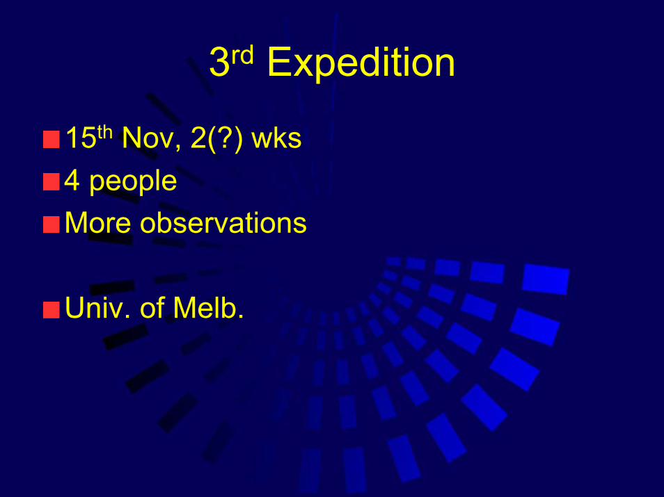
3rd Expedition
15th Nov, 2(?) wks4 peopleMore observations
Univ. of Melb.

4th Expedition
1st wk Jan# of peopleRemaining beamformers3 ReceiversThe correlator
Roger, Bart, Divya*, Miguel*, Jackie*, Alan Whitney, Mike
32T target timeline
This meeting
Con
tract
with
Bur
ns
Indu
strie
s fo
r 32
tiles
Dep
loy
32 ti
les
on s
ite
+ pr
elim
inar
y te
stin
g
Obs
erva
tions
Beamformers (8)
1st Receiver
32 Tiles delivered in Australia
Field testing 8TField testing 32T
Beamformers (9-32)
Receivers (2-4)
PFB
Correlator
Obs
ervi
ng C
ampa
igns
as
nee
ded
Inst
all r
emai
ning
BFs
, Rec
eive
rs
and
Cor
rela
tion
-dep
loym
ent
and
field
tes
ting
Decision on site
Ground-screen
Decision on Corr. approach
Data capture device
Internet (Vsat)
Office trailer
Generator
Lab integration of beamformer,
receiver & data capture device
Lab integration of receiver & correlator
Inst
all 8
bea
mfo
rmer
s+
Obs
erva
tions
usi
ng s
ome
data
ca
ptur
e de
vice