th century 4-wheel passenger vans please read to the …
TRANSCRIPT

SERKits Carriage Instructions © Text and pictures Dan Garrett 2010 Page 1 of 14
SERKits
Assembly Instructions
19th CENTURY 4-WHEEL PASSENGER VANS
based on SER/SE&CR prototypes
PLEASE READ TO THE END BEFORE STARTING THE KIT
Contents
Introduction
These instructions cover both the SERKits Passenger Luggage Van (PLV) and Passenger Brake Van (PBV).
2 Resin sides 2 Resin ends 2 solebars with axleboxes [16] PBV: resin guard’s seat PBV: resin roof PLV: rolled styrene roof 5in of p-bronze rod PBV: 2x 10” 0.5mm brass rod
PLV 6” 2x70mm 0.7mm N/S rod
Comp underframe etch (with brake gear for PBV92)
PBV only: birdcage etch Carriage steps etch
1.2mm brass rod PBV: 60mm PLV: 30mm
Glazing: PBV 50x60mm PBV: Glazing template
PBV: 2x126mm 2x1 styrene PLV: 2x112mm 2x1 styrene
PBV: 2x126mm 4x1 styrene PLV: 2x112mm 4x1 styrene
PBV92: 2x126mm 6x2 styrene
60 thou Styrene floor, PBV: black 121.5 x 45.5mm PLV: white 114.5 x 45.5mm
40 thou styrene PBV: 90 x 45.5mm for partition & end step PLV: 45.5 x 25mm – spacer & end step
PBV only: 10” 0.8mm ¼-round styrene
BAG 1 4 buffer stocks Hooped for PLV [40] 4-ribbed for PBV [45A]
4 buffers – 2 flat, 2 curved [33] 2 coupling hooks
4 combined axlebox + spring castings PBV: high grease a’box [74C] PLV: low grease a’box [1]
BAG 2 4 small door handles for dog boxes. [5] PBV: 2 larger door handles [91] for guard’s door
Louvres: PBV: 2x panel width & 2 for dog-boxes PLV: 4 for dog-boxes [91]
60mm of 0.5mm styrene rod
PBV: rear lamp [10,L21,L21A] PBV: brake handle Pins: PBV: ~50; PLV ~35 BAG 3 PBV64: Slide Brake PBV92: Auto or Smiths vac
cylinder and stanchions
Scale drawing

SERKits Carriage Instructions © Text and pictures Dan Garrett 2010 Page 2 of 14
A typical SER passenger train had a mix of carriages for different classes of passenger, with a passenger brake van at one end and a brake second or brake third at the other. Express and continental trains might have had several PBVs in the same train, each with a guard, to increase the braking capacity. This was certainly the case with the ill-fated express carrying Charles Dickens and his young mistress back from Folkestone, which came to grief on the low viaduct near Staplehurst.
Passenger luggage vans would have been used for cross-channel trains where passengers had high volumes of luggage; in private trains where the family and servants took huge quantities of clothes and other belongings; and would sometimes have been pressed into service to carry soft fruit in crates during the picking season.
SER Kits uses high quality resin that withstands a degree of flexing. It can be drilled and filed with ordinary care without snapping unexpectedly. But take care around thin sections like window frames. If you follow the instructions and take your time, you should be able to achieve a highly detailed model which will be an asset to your layout.
Compensation
• This is by the rocking method. However the rocker is not loose, but controlled either by the flexing of the W-iron tie-rods which are of springy nickel silver rod, or by phosphor bronze spring wires. If you feel that compensation is unnecessary for 7mm Finescale 4-wheelers, either solder the rocking assembly solid, or discard the rocker and pack the axleguard etch with approx 3.5mm thick styrene or wood.
• The axleboxes are fitted over Slaters’ wheel bearings and carry cosmetic springs. On the rocking unit, the springs move between the spring hangers and when going over track joints or point frogs, the up and down movement looks realistic.
General methods
• The resin castings are made in two part moulds, and it’s almost impossible to produce a casting without minor imperfections caused by air bubbles. I reject those that have too many. Look out for tiny gaps in the beading around panels and tiny holes in thin edges such as window frames. Fill with e.g. Squadron putty or Humbrol filler. Hold the casting up to the light, and if you can see an internal air-bubble, consider cutting a small hole in the rear, and pressing filler into the small void.
• I find the homemade tool in the photo very useful for cleaning up inside panelled areas where normal tools would remove detail. The strip wood is 3 or 4mm square.
• Check the tiny detail of cosmetic bolts. If you are bothered by any that have failed to cast, remedy this as follows: drill 0.55mm and superglue tiny protruding lengths of the supplied 0.5mm plastic rod into the holes.
• The whole kit can be assembled using two-part 5minute epoxy resin glue such as Araldite or Devcon, and/or superglue.
• For strength, etched parts are intended to be fixed to the resin body with small dressmakers’ pins – ‘Lill’ pins – as well as glue. Perfectionists will square the heads.
• I recommend ‘paint as you go’, where suggested in the instructions. Leaving painting until after completion can cause difficulties, especially the interior and underside.
• This resin takes paint easily and primer is not needed (unlike etched brass). However a plain coat of paint is useful to show up flaws and gaps needing attention before you start the paint job proper.
Getting the resin castings ready
1. Clean up the castings, removing casting sprues from the edges of some castings. NOTE: the sides have ‘sticking-out-bits’ at the end. These represent lamp-irons and fixings for the end grab-rails as shown in the diagram. Do NOT accidentally remove.
2. Cleaning up round the guard’s windows: use a craft knife and/or triangular needle file. Use a light touch. You can usually see best from the inside where to file to. The windows are the most fragile part of the casting, but are finally strengthened by the glazing. Look out for little resin spheres inside the window frames which will prevent the glazing lying flat. If any, chisel off with a square-edge craft knife.
3. Prepare the sides for fittings by drilling 0.8mm for dog-box and guard’s door handles. Check the positions for the cast louvres against the drawing. Trial the louvres against (PBV: 2 dog boxes 2 top louvres; PLV: 4 dog boxes. The PBV top louvres are a snug fit, and I suggest drilling a hole behind them

SERKits Carriage Instructions © Text and pictures Dan Garrett 2010 Page 3 of 14
so they can easily be pushed out before glueing. The dog box louvres need the flanges trimming down (end cutter) and the holes in the resin cleaned gently with a fine flat needle file. Glue all four louvres inn place.
4. Prepare the ends by clearing the buffer-stock holes with a 3.5mm drill, and the draw-hook slot with a fine needle file or 1.2mm drill. Also drill 0.8mm 14mm apart, either side of the coupling hole slot for the safety chain eyes. Drill 0.6mm to take the end grab-rails as in the diagram, and – on one end only, also drill to take pins for the etched steps. Refer to the drawing and to the photos below: LH: PLV; centre: PBV64; RH: PBV92. Use the etchings for exact positioning and for the steps off the headstock, it’s sensible first to temporarily fit the buffer stock castings.
Assembling the body
5. The photos show what you’re aiming for: passenger van on the left, brake van on the right.
6. Check the styrene floor fits snugly in the end slots. Trial the sides for fit, and if necessary, slightly reduce the length/width of the floor.
7. When satisfied, glue the floor into one end, then glue one side to end and floor, checking that top strapping detail lines up. Hold the body down on a truly flat surface (preferably plate glass) until the glue has set.
8. Glue the second side to the end, but not to the floor to allow for possible adjustment.
9. With the body still on a flat surface, trial the other end and if a snug fit, glue the second side to the floor, then add the second end.
10. Glue buffer stock castings into solebar holes, using a length of rod from one end to the other so that they are correctly aligned.
PBV only
11. There is a partition between the guard’s and luggage compartments immediately ahead of the guard’s door. This is shown as dotted line in the drawing, and can be seen in the above photo. Note that it stops short of the roof and a horizontal ‘desk’ projects forward over the luggage compartment, before the partition continues upwards to the roof level with with observatory front.
SERKits Carriage Instructions © Text and pictures Dan Garrett 2010 Page 4 of 14
12. Make this partition from the supplied 40 thou (1mm) styene, 45.5mm wide, cutting one length 19.5mm for the lower part, and a second 19.5mm wide for the desk. On the remainder, use the roof as a template to mark the top profile, then cut across 9.5mm below the top corners.
13. Weld the partition parts to each other and to the floor, gluing them to the resin sides with superglue or resin glue.
14. The remainder of the styrene can be used as a forward cross-brace.
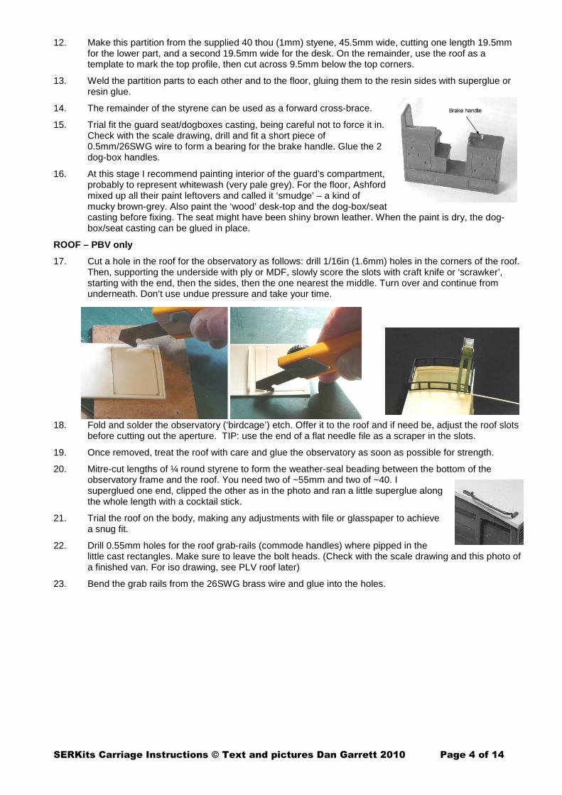
15. Trial fit the guard seat/dogboxes casting, being careful not to force it in. Check with the scale drawing, drill and fit a short piece of 0.5mm/26SWG wire to form a bearing for the brake handle. Glue the 2 dog-box handles.
16. At this stage I recommend painting interior of the guard’s compartment, probably to represent whitewash (very pale grey). For the floor, Ashford mixed up all their paint leftovers and called it ‘smudge’ – a kind of mucky brown-grey. Also paint the ‘wood’ desk-top and the dog-box/seat casting before fixing. The seat might have been shiny brown leather. When the paint is dry, the dog-box/seat casting can be glued in place.
ROOF – PBV only
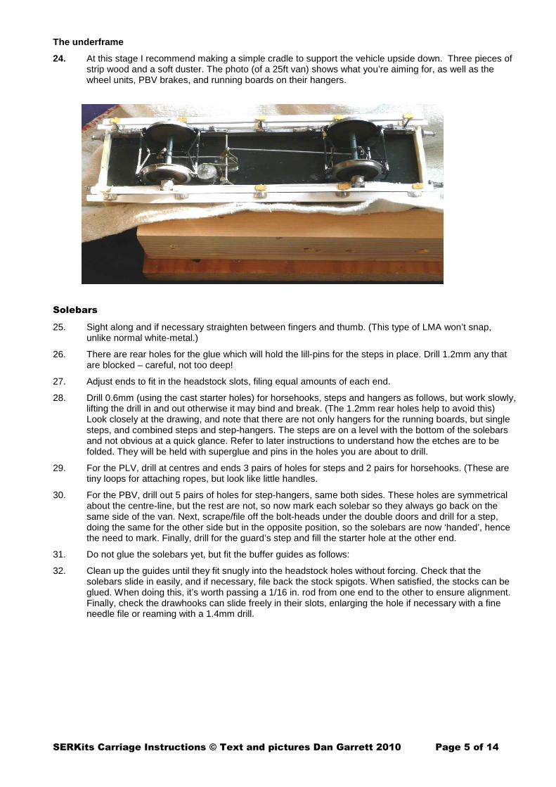
17. Cut a hole in the roof for the observatory as follows: drill 1/16in (1.6mm) holes in the corners of the roof. Then, supporting the underside with ply or MDF, slowly score the slots with craft knife or ‘scrawker’, starting with the end, then the sides, then the one nearest the middle. Turn over and continue from underneath. Don’t use undue pressure and take your time.
18. Fold and solder the observatory (‘birdcage’) etch. Offer it to the roof and if need be, adjust the roof slots before cutting out the aperture. TIP: use the end of a flat needle file as a scraper in the slots.
19. Once removed, treat the roof with care and glue the observatory as soon as possible for strength.
20. Mitre-cut lengths of ¼ round styrene to form the weather-seal beading between the bottom of the observatory frame and the roof. You need two of ~55mm and two of ~40. I superglued one end, clipped the other as in the photo and ran a little superglue along the whole length with a cocktail stick.
21. Trial the roof on the body, making any adjustments with file or glasspaper to achieve a snug fit.
22. Drill 0.55mm holes for the roof grab-rails (commode handles) where pipped in the little cast rectangles. Make sure to leave the bolt heads. (Check with the scale drawing and this photo of a finished van. For iso drawing, see PLV roof later)
23. Bend the grab rails from the 26SWG brass wire and glue into the holes.
SERKits Carriage Instructions © Text and pictures Dan Garrett 2010 Page 5 of 14
The underframe
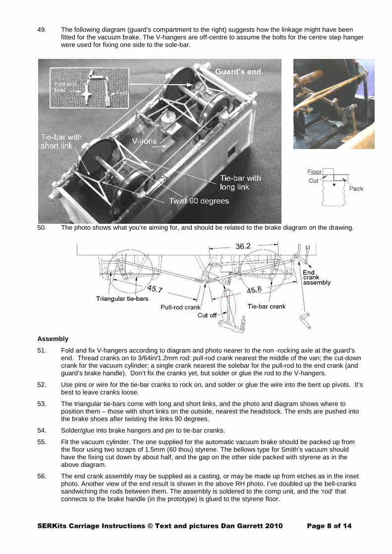
24. At this stage I recommend making a simple cradle to support the vehicle upside down. Three pieces of strip wood and a soft duster. The photo (of a 25ft van) shows what you’re aiming for, as well as the wheel units, PBV brakes, and running boards on their hangers.
Solebars
25. Sight along and if necessary straighten between fingers and thumb. (This type of LMA won’t snap, unlike normal white-metal.)
26. There are rear holes for the glue which will hold the lill-pins for the steps in place. Drill 1.2mm any that are blocked – careful, not too deep!
27. Adjust ends to fit in the headstock slots, filing equal amounts of each end.
28. Drill 0.6mm (using the cast starter holes) for horsehooks, steps and hangers as follows, but work slowly, lifting the drill in and out otherwise it may bind and break. (The 1.2mm rear holes help to avoid this) Look closely at the drawing, and note that there are not only hangers for the running boards, but single steps, and combined steps and step-hangers. The steps are on a level with the bottom of the solebars and not obvious at a quick glance. Refer to later instructions to understand how the etches are to be folded. They will be held with superglue and pins in the holes you are about to drill.
29. For the PLV, drill at centres and ends 3 pairs of holes for steps and 2 pairs for horsehooks. (These are tiny loops for attaching ropes, but look like little handles.
30. For the PBV, drill out 5 pairs of holes for step-hangers, same both sides. These holes are symmetrical about the centre-line, but the rest are not, so now mark each solebar so they always go back on the same side of the van. Next, scrape/file off the bolt-heads under the double doors and drill for a step, doing the same for the other side but in the opposite position, so the solebars are now ‘handed’, hence the need to mark. Finally, drill for the guard’s step and fill the starter hole at the other end.
31. Do not glue the solebars yet, but fit the buffer guides as follows:
32. Clean up the guides until they fit snugly into the headstock holes without forcing. Check that the solebars slide in easily, and if necessary, file back the stock spigots. When satisfied, the stocks can be glued. When doing this, it’s worth passing a 1/16 in. rod from one end to the other to ensure alignment. Finally, check the drawhooks can slide freely in their slots, enlarging the hole if necessary with a fine needle file or reaming with a 1.4mm drill.

SERKits Carriage Instructions © Text and pictures Dan Garrett 2010 Page 6 of 14
Basic order of underframe assembly
• Solder folds of wheel assembly (the photo is the etch for the PLV
• Loose fit bearings and wheels • Fit assemblies • Fit solebars • (Fit Vee-hangers, vacuum cylinder,
crossrod and cranks • Fit the brake linkage, tying the brakes • Fit vacuum linkage) • Fit running boards, • Fit T-hangers, axleboxes and springs
33. Before making the wheel assemblies, fixed and rocking, I prefer to side-track and paint the wheels. This is best if you’re going for the full Mansell patent: wooden segments teak and outer steel tyre white. Use 3ft 6in Mansell Wheels (GWR type) from e.g. Slaters. If you’re using Slaters wheels, then the centre can be black and also the inner rim. This paint scheme is difficult to apply in situ, surrounded by running gear.
34. PBVs only. Two types of brake can be fitted: the original slide brake dating from at least the 1850s, or the more modern clasp brake. If you’re fitting the slide brake, then, before folding, 0.6mm locator holes must be drilled in the W-irons for the slide brake cross-slide.
35. The photo and diagrams should make clear what you’re aiming for.
36. Reinforce folds with solder or 2-part quick-set epoxy resin such as Araldite. Choose appropriate keeper plates, punch rivets and solder to bottom of W-irons. (For better appearance, drill out keeper plates, and fix with lill pins after squaring the heads.) Use 3/64” brass rod to pivot the rocking W-iron.
37. With the PBV, as you cut out the small parts, make sure not to lose them. Remove the A shaped brake ties. Spring them into the brake hangers, letting them hang down (towards the floor at this stage). The A-frames with the short extension go nearest the PBV ends. Confirm with brake arrangement on the main drawing. Solder a spare brake block onto the projecting spigot.
38. There’s not much clearance for the wheel treads so offer them up. You may need to burr out small rectangles in the floor. Also, file the corners of the rocking assembly. The wheels must run freely.
39. With both PBV and PLV, the rocking is controlled by the tie rods between the W-irons, made from 0.7mm nickel-silver wire rod. In some etches there is a half-etched recess for the wire; in others, there’s a half-etched tag that can be curled round the wire. Tin these with solder now. Later, when fixing the units under the floor, it’s important to ensure the soldering points face towards the middle of the vehicle.
40. Rinse off any acid, (dilute bicarb solution, then water.) Spray with an etch primer and then black.
41. Loose fit bearings and wheels. Solder the bearings, pushing in so that the wheels have virtually no sideways play and are centred.

SERKits Carriage Instructions © Text and pictures Dan Garrett 2010 Page 7 of 14
Underframe fittings
42. The photo shows the next stages.
43. Rest the vehicle on W-irons on track, as in the photo of a coupe carriage. DON’T glue anything yet! Some packing between W-irons and floor may be necessary and can be glued to the floor now. Note that the exact height of the rocking W-iron depends on how you’ve folded the parts. I’ve found that there can be as much as 1/2mm variation between different attempts. (Etched kits rarely mention the variability of folds…) For packing use paper, styrene or cardboard. Note that on the PBV, the fixed unit should be fitted at the guard’s compartment end.
44. Glue the solebars and wheel assemblies, lining up W-irons with the bolt heads cast in the solebars. When gluing the PBV solebars, make sure they’re on the correct sides.
45. The springs on the fixed W-irons should be trimmed down to be a snug fit between the spring hangers, while on the rocking W-irons they need to have just sufficient clearance to move up and down, while appearing to join. (See earlier diagrams.) The springs may need to be straightened a little. Glue them to the wheel bearings.
46. Recheck the rocker is free to move.
47. Solder lengths of 0.7mm nickel-silver wire between W-irons to form tie-bars and to spring the rocker unit.
PBV only: fitting the brake gear
48. The etch is generic and contains parts for different crank and lever arrangements. Make pivots for the brake linkage from 26SWG brass wire or dress-maker’s pins. Note that the etch supplied may be slightly different from the one in the photo. The link dimensions may differ slightly on your model. Where an exact length is not available, cut out a longer one, cut in half, and solder an overlap to give the correct length.
SERKits Carriage Instructions © Text and pictures Dan Garrett 2010 Page 8 of 14
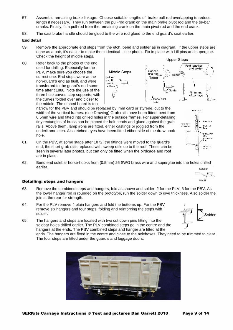
49. The following diagram (guard’s compartment to the right) suggests how the linkage might have been fitted for the vacuum brake. The V-hangers are off-centre to assume the bolts for the centre step hanger were used for fixing one side to the sole-bar.
50. The photo shows what you’re aiming for, and should be related to the brake diagram on the drawing.
Assembly
51. Fold and fix V-hangers according to diagram and photo nearer to the non -rocking axle at the guard’s end. Thread cranks on to 3/64in/1.2mm rod: pull-rod crank nearest the middle of the van; the cut-down crank for the vacuum cylinder; a single crank nearest the solebar for the pull-rod to the end crank (and guard’s brake handle). Don’t fix the cranks yet, but solder or glue the rod to the V-hangers.
52. Use pins or wire for the tie-bar cranks to rock on, and solder or glue the wire into the bent up pivots. It’s best to leave cranks loose.
53. The triangular tie-bars come with long and short links, and the photo and diagram shows where to position them – those with short links on the outside, nearest the headstock. The ends are pushed into the brake shoes after twisting the links 90 degrees.
54. Solder/glue into brake hangers and pin to tie-bar cranks.
55. Fit the vacuum cylinder. The one supplied for the automatic vacuum brake should be packed up from the floor using two scraps of 1.5mm (60 thou) styrene. The bellows type for Smith’s vacuum should have the fixing cut down by about half, and the gap on the other side packed with styrene as in the above diagram.
56. The end crank assembly may be supplied as a casting, or may be made up from etches as in the inset photo. Another view of the end result is shown in the above RH photo. I’ve doubled up the bell-cranks sandwiching the rods between them. The assembly is soldered to the comp unit, and the ‘rod’ that connects to the brake handle (in the prototype) is glued to the styrene floor.
SERKits Carriage Instructions © Text and pictures Dan Garrett 2010 Page 9 of 14
57. Assemble remaining brake linkage. Choose suitable lengths of brake pull-rod overlapping to reduce length if necessary. They run between the pull-rod crank on the main brake pivot rod and the tie-bar cranks. Finally, fit a pull-rod from the remaining crank on the main pivot rod and the end crank.
58. The cast brake handle should be glued to the wire rod glued to the end guard’s seat earlier.
End detail
59. Remove the appropriate end steps from the etch, bend and solder as in diagram. If the upper steps are done as a pair, it’s easier to make them identical – see photo. Fix in place with Lill pins and superglue. Check the height of middle steps.
60. Refer back to the photos of the end used for drilling. Especially for the PBV, make sure you choose the correct one. End steps were at the non-guard’s end as built, and were transferred to the guard’s end some time after c1888. Note the use of the three hole curved step supports, with the curves folded over and closer to the middle. The etched board is too narrow for the PBV and should be replaced by Imm card or styrene, cut to the width of the vertical frames. (see Drawing) Grab rails have been fitted, bent from 0.5mm wire and fitted into drilled holes in the outside frames. For super-detailing tiny rectangles of brass can be pipped for bolt heads and glued against the grab rails. Above them, lamp irons are fitted, either castings or joggled from the underframe etch. Also etched eyes have been fitted either side of the draw hook hole.
61. On the PBV, at some stage after 1872, the fittings were moved to the guard’s end, the short grab rails replaced with sweep rails up to the roof. These can be seen in several later photos, but can only be fitted when the birdcage and roof are in place.
62. Bend end solebar horse-hooks from (0.5mm) 26 SWG brass wire and superglue into the holes drilled earlier.
Detailing: steps and hangers
63. Remove the combined steps and hangers, fold as shown and solder, 2 for the PLV, 6 for the PBV. As the lower hanger rod is rounded on the prototype, run the solder down to give thickness. Also solder the join at the rear for strength.
64. For the PLV remove 4 plain hangers and fold the bottoms up. For the PBV remove six hangers and four steps, folding and reinforcing the steps with solder.
65. The hangers and steps are located with two cut down pins fitting into the solebar holes drilled earlier. The PLV combined steps go in the centre and the hangers at the ends. The PBV combined steps and hanger are fitted at the ends. The hangers are fitted in the centre and close to the axleboxes. They need to be trimmed to clear. The four steps are fitted under the guard’s and luggage doors.

SERKits Carriage Instructions © Text and pictures Dan Garrett 2010 Page 10 of 14
66. Make up running boards from pieces of 2x1mm styrene strip cut to suit the drawing and glued behind 4x1mm styrene strip. A piece of metal angle makes a useful jig as in the photo below. (If the styrene sticks to the metal, you’re applying too much solvent – use a smaller brush.)
67. Offer the running boards to the carriage and file to fit around the axleboxes as in the diagram.
68. Check that all the hangers are vertical, and the steps and hanger toes horizontal. Glue the running boards to the hangers. 2-part epoxy resin glue is forgiving because it has ‘thickness’. The photo shows the PLV.
69. Add door-handles, small ones for dog boxes (PBV: also on guard’s seat) and larger ones for Guard’s door on the PBV.
Handrails
70. Bend square-U shaped pieces of 26 SWG brass wire to make handles for the double doors and insert in the holes drilled previously.
71. Making and fitting the side grab-rails is ticklish. If you're manipulatively challenged (clumsy? – perish the thought!), I'd suggest it's better to leave them off than to have badly-made ones that are not square and parallel with the framing. Alternatively, you could try using tiny split pins to hold the rails. The half-way solution is to fit the horizontal rails only. For the intrepid, here are my suggestions:
72. Cut pieces of brass wire about 4mm long (4 for the PBV, 8 for the PLV) and tin the ends. Glue them into the middle holes of the horizontal rails as in the diagram (of the PBV) to protrude about 1mm. Cut more brass wire for the horizontals and bend the ends at right angles to fit the drilled holes. Tin them where they’ll touch the middle pins, insert and touch each join with a hot iron. PBV only: bend the curves on the verticals, bend the ends at right angles to fit into the holes in the framing and solder at the top. Alternatively, you could replace the solder with resin glue but the model will need gentler handling.
73. Photos over the page (before cleaning up).

SERKits Carriage Instructions © Text and pictures Dan Garrett 2010 Page 11 of 14
74. Roofs
75. Adjust overhangs and sand sides and ends smooth. Check the curve of the styrene roof, rolling it more between fingers or with rollers if it’s become flatter in the box.
76. For the PLV, note that one end should have little fixings for end grab rails –see scale drawing and diagram opposite. Drill 0.55mm and bend wire to fit. The flat fixings can be made from 1mm wide flat brass pipped for the bolt heads and fishtailed to fit against the wire.
77. For PBV64, grab rails should be fitted as for the PLV, but the flat fixings are moulded in the roof. Drill 0.55mm into the fishtails and bend wire as in the diagram.
78. For PBV92, the flat fixings should be sanded off, as the sweep rails are fixed to the birdcage roof, with flat fixings as for the PLV.
Painting
79. At this stage, I recommend painting all the etches with etch primer.
80. When dry, paint the whole carriage underframe black – solebars, headstocks, steps, W irons etc - inside and out. Paint the body purple brown, and finish with matt varnish.
81. Paint roof white (for new) and handrails and other ironwork black.
Buffers and drawgear
82. The kits have an etched screw coupling which is strong and easy to assemble, as well as etched safety chain hooks and eyes. If looks are more important than strength, I can supply castings for hooks, coupling screws and bob weights plus wire to form the loops. Formed this way, the couplings are to scale and quite tiny, but stronger than they appear. They work well for me in period trains of to 12 or 15 vehicles. Of course, sudden ‘snatching’ can break them – as with the prototype.
83. Clean up the buffers. (Note that two are flat-heads and two are round-heads. Check with the drawing to get them the right way round!) Some modellers have been worried about the fragility of these buffers, but the metal is pliable, and can be bent straight again after an accident! I’ve been using them for more than 30 years now.
84. The buffers should need little adjustment in order to slide easily in the stocks. If necessary, gently run a 1.7mm drill through the holes in the buffer stocks, and scrape the buffer shanks along the length with a craft knife, rotating the buffer between each scrape. Don’t file the shanks across the width – the roughness will stop the buffers sliding smoothly. The buffers should slide easily in and out. If not, your derailment rate will rise!
85. Measure 14.5mm along the shanks from the back of the buffer head. Drill a hole 0.6 mm (No 73) right through each shank to take the spring wire. If you're squeamish about drilling through a narrow rod, make a simple jig from a couple of inches of 1/16" I.D. brass tube. Drill the hole through the brass tube at the correct distance from the end. It's then a simple matter to feed each buffer into the tube for

SERKits Carriage Instructions © Text and pictures Dan Garrett 2010 Page 12 of 14
drilling. This jig is also useful for protecting the shank if you paint the buffer heads before assembly (rear – black, front and edge – teak colour).
86. The kit has both etched and cast drawhooks (coupling hooks). The latter look better. If you choose to use them with the etched screw couplings, you’ll need to make a saw-cut into the front hole in order to slide the top link in, and close it with glue or 70º solder.
87. Run the phosphor-bronze wire through your fingers to straighten it, then cut off two pieces 41.5 mm long. Checking with the diagram, slide the wire through the hole in the coupling hook just behind the headstock, and then into the hole in the right-hand buffer shank. The wire can now be pulled back into the hole in the other buffer shank. (It’s much easier to do than explain)
88. Solder the wire to the hook (tin beforehand with normal solder and use 700deg to the hook), or use a blob of resin glue. When set, the ends of the wire can be bent to touch the headstock so that the buffer heads protrude fully and the draw-hook is held back by the spring.
89. Solder or glue bob weights into the holes in the coupling centres. Fold coupling links around the coupling centres, insert long link into the slot in the coupling hook, and fold lip down to hold.
90. Safety chains: Insert eyes through washer plates and glue into holes drilled earlier. If modelling vehicles pre-1890, hang safety chain hooks from eyes with short lengths of chain cut from the length supplied. The safety chains were often looped up out of the way by threading the hook through the eye.
Finishing
91. Cut glazing for the PBV guard’s doors and observatory, using printout guide, but check the fit of each piece before gluing. Glue by using a wooden toothpick to first place a thin line of Evostik around the edge of each window-frame in turn.
92. The rear lamp casting will need a slot drilled out to fit the lamp-iron, or else file the rear collar away and replace with a square U-shaped piece of thin metal (shim). Drill either side of the lamp chimney 0.55mm and make a tall U-shaped handle with wire. I believe the lamp body was painted red. The ‘glass’ can be painted shiny dark red. The lamp should be on the right-hand side of the carriage, looking towards the locomotive.
93. Glue roof to body with Evostik.
94. Sight along all the steps and straighten them up where necessary.
SERKits Carriage Instructions © Text and pictures Dan Garrett 2010 Page 13 of 14
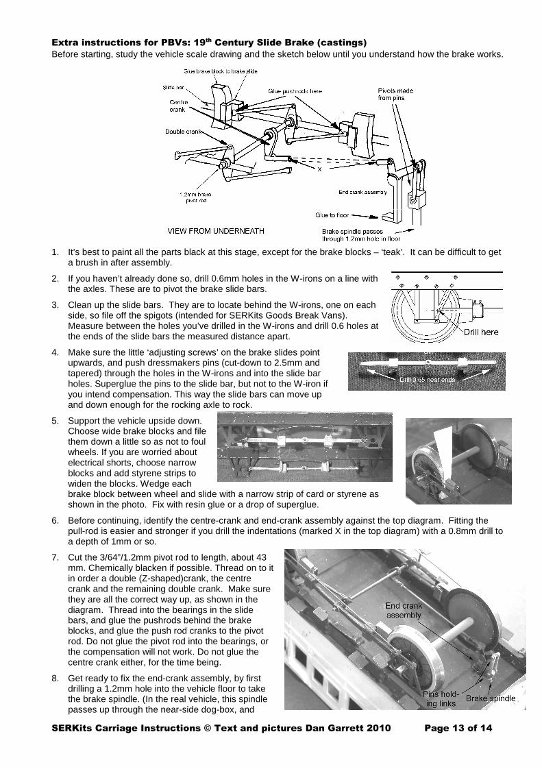
Extra instructions for PBVs: 19th Century Slide Brake (castings)
Before starting, study the vehicle scale drawing and the sketch below until you understand how the brake works.
1. It’s best to paint all the parts black at this stage, except for the brake blocks – ‘teak’. It can be difficult to get a brush in after assembly.
2. If you haven’t already done so, drill 0.6mm holes in the W-irons on a line with the axles. These are to pivot the brake slide bars.
3. Clean up the slide bars. They are to locate behind the W-irons, one on each side, so file off the spigots (intended for SERKits Goods Break Vans). Measure between the holes you’ve drilled in the W-irons and drill 0.6 holes at the ends of the slide bars the measured distance apart.
4. Make sure the little ‘adjusting screws’ on the brake slides point upwards, and push dressmakers pins (cut-down to 2.5mm and tapered) through the holes in the W-irons and into the slide bar holes. Superglue the pins to the slide bar, but not to the W-iron if you intend compensation. This way the slide bars can move up and down enough for the rocking axle to rock.
5. Support the vehicle upside down. Choose wide brake blocks and file them down a little so as not to foul wheels. If you are worried about electrical shorts, choose narrow blocks and add styrene strips to widen the blocks. Wedge each brake block between wheel and slide with a narrow strip of card or styrene as shown in the photo. Fix with resin glue or a drop of superglue.
6. Before continuing, identify the centre-crank and end-crank assembly against the top diagram. Fitting the pull-rod is easier and stronger if you drill the indentations (marked X in the top diagram) with a 0.8mm drill to a depth of 1mm or so.
7. Cut the 3/64”/1.2mm pivot rod to length, about 43 mm. Chemically blacken if possible. Thread on to it in order a double (Z-shaped)crank, the centre crank and the remaining double crank. Make sure they are all the correct way up, as shown in the diagram. Thread into the bearings in the slide bars, and glue the pushrods behind the brake blocks, and glue the push rod cranks to the pivot rod. Do not glue the pivot rod into the bearings, or the compensation will not work. Do not glue the centre crank either, for the time being.
8. Get ready to fix the end-crank assembly, by first drilling a 1.2mm hole into the vehicle floor to take the brake spindle. (In the real vehicle, this spindle passes up through the near-side dog-box, and
SERKits Carriage Instructions © Text and pictures Dan Garrett 2010 Page 14 of 14
terminates in a winding handle. As the handle is rotated, a thread on the spindle lifts a block on the end crank to apply the brakes.) The hole should be 8mm from the headstock and 11mm from the near-side solebar (The solebar furthest from you, if you’re looking at your model as in the diagram above.) Glue the end crank assembly as in the photo (of a brake 2nd).
9. Cut the 0.7mm pull rod to fit between end crank and centre crank (about 39mm).
10. Cut down two dressmaker's pins to form pivots for the pair of straight links to be fitted between end crank and the block on the bottom of the gear spindle.
Historical Note
These vans are typical of 4-wheelers used in the mid-19th Century. Long trains of them were used on main lines, and short ones on branch lines. On the SER these carriages formed part of the express train involved in the Staplehurst accident which could have killed Charles Dicken or led to the discovery of his affair with a young actress. In the 1880s the carriages were replaced on main lines by 6-wheelers and bogies, while the 4-wheelers continued in use branch lines such as those to West Wickham and Hayes, Hawkhurst, Westerham, Sandgate, etc. They lasted into the early years of the 20th Century before withdrawal. A few survived longer as Engineering and Maintenance Dept. stock..
The kits allow most stages of the vans’ lives to be modelled:
• In the 1880s many were piped for Smiths vacuum brake. Later some were fitted for the automatic vacuum.
• Some time after 1872, the single solebar steps were replaced with an upper running board.
Livery and lettering
As to the exact shade of brown, there is no definitive answer. LSWR/SR wagon brown approximates the 19th Century purple brown if you mix in some red.
Headstocks and solebars and ironwork were painted black (unlike wagons) and varnished. Roofs were originally white, so I use white with dashes of black and yellow for a bit of weathering – all different!
The guard’s compartment was possibly whitewashed. I can’t imagine it was combed.
The wheels were to Mansell’s patent, with varnished teak segments between hub and tyre, so I paint the hub black, the segments ‘teak’ and the tyres (weathered) white, according to patent and photos. The axles were supposed by patent to be painted blue. This was an expensive pigment and was presumably intended to show that these were classy wheels.
The last stage is to add the lettering, using the SER-Kits transfer sheet.
Finally:
I hope you’ve enjoyed assembling this kit. If you’ve had any problems, let me know, and I’ll try to find a solution for later kits. I’m hoping at some stage to detail the SER’s fairly complicated lettering and numbering arrangement which no-one has yet chronicled. In the meantime, modellers will need to rely on photos.
© text and photos 2018 Dan Garrett,
21 Weald Close, Weald,
Sevenoaks, Kent TN14 6QH
Email: [email protected]