th 400 automatic transmission - street2mud.comstreet2mud.com/webfiles/jeep th-400 transmission...
TRANSCRIPT

TH 400 AUTOMATIC TRANSMISSION 7-1
Page GENERAL 1
Towing the Vehicle 1 GENERAL DESCRIPTION 1
Planetary Gear Train 2 Sprag and Roller Clutches 3 Power Flow 3
HYDRAULIC SYSTEM 3 Pressure Control 3 Vacuum Modulator 4 Governor Assembly 4 Function of Valves and Control Units 4
SERVO OPERATION 5 DETENT AND REGULATOR VALVES 6 TRANSMISSION LINKAGE ADJUSTMENT 6 ROAD TEST 6 DIAGNOSIS 7
Page
MINOR MAINTENANCE AND ADJUSTMENTS 17 TRANSMISSION REMOVAL AND INSTALLATION 18 DISASSEMBLY 18 SUB-ASSEMBLY OVERHAUL 23
Gear Unit Disassembly 23 Governor 24 Rear Servo 25 Control Valve 25 Oil Pump 26 Forward Clutch 28
Direct Clutch and Intermediate Sprag 30 Center Support 32 Reaction Carrier, Roller Clutch and Output Carrier . . . 33
ASSEMBLY 38 SPECIFICATIONS 41
GENERAL Before attempting any service or
repair on the automatic transmission, it is extremely important that this section be read carefully and the operation of this transmission be thoroughly understood.
All automatic transmissions used have three-speeds forward and one-speed reverse. The shifting is accomplished by manually selecting the gear desired with the shift lever mounted on the steering column. Linkage from the lever shifts the transmission in the gear selected. The automatic transmission then hydraulically changes the gears, selecting the proper gear ratio for the accompanying conditions.
This section carries information on theory of operation, including detailed description of the mechanical functions; maintenance and adjustments, and overhaul. It is most important that vehicles having a combination automatic transmission and 4-wheel drive use the proper terminology when describing various operational terms. To avoid possible confusion it is suggested the following terminology be used.
Automatic Transmission Gear Selections: Park, Reverse, Neutral, Drive, Drive 2, and Drive 1.
Transfer Case: 2WD, 4WD High, Neutral, 4WD Low.
Each automatic transmission has its own serial number. This number is stamped on a plate, at right side of transmission case, to front of governor assembly.
Any communication concerning a automatic transmission should include the serial number.
Towing The Vehicle
The vehicle may be towed forward in the normal manner without damage to the 4-wheel-drive mechanism. The automatic transmission and transfer case must be in neutral position.
Should it be necessary, however, to lift the rear wheels and tow the vehicle in reverse, be sure to remove the front axle shaft driving flanges to prevent the front differential from rotating.
Should the driving flanges be removed, a cover should be improvised that will prevent dirt from entering the wheel bearings. The vehicle can be towed forward or backward at reasonable safe speeds (such as specified by state law) for any distance.
GENERAL DESCRIPTION
The automatic transmission is a fully automatic unit consisting primarily of a 3-element hydraulic torque converter and a compound planetary gear set, Fig. 1. Three multiple-disc clutches, one sprag, one roller clutch and two bands provide the friction elements required to obtain the desired function of the compound planetary gear set.
The torque converter couples the engine to the planetary gears through oil and provides hydraulic torque multiplication when required. The compound planetary gear set produces three forward speeds and reverse, (Fig. 2).
The 3-element torque converter consists of a pump or driving member, a turbine or driven member, and a stator assembly. The stator is mounted on a
one-way roller clutch which will allow the stator to turn clockwise, but not counterclockwise, when viewed from the front.
The torque converter housing is filled with oil and is attached to the engine crankshaft by a flex plate; thus it a l ways rotates at engine speed. The converter pump is an integral part of the converter housing; therefore the pump blades, rotating at engine speed, set the oil within the converter into motion and direct it to the turbine, causing the turbine to rotate.
As the oil passes through the turbine, it is traveling in such a direction that if it were not redirected by the stator it would hit the rear of the converter pump blades and impede its pumping action, (Fig. 3). So at low turbine speeds, the oil is redirected by the stator to the converter pump in such a manner that it actually assists the converter pump to deliver power or multiply engine torque.
As turbine speed increases, the di-rection of the oil leaving the turbine changes and flows against the rear side of the stator vanes in a clockwise direction. Since the stator is now impeding the smooth flow of oil, its roller clutch releases and it revolves freely on its shaft. Once the stator becomes inactive, there is no further multiplication of engine torque within the converter. At this point, the converter is merely acting as a fluid coupling as both the converter pump and turbine are being driven at approximately the same speed — or at a one-to-one ratio.
A hydraulic system pressurized by a gear type pump provides the working

7-2 AUTOMATIC TRANSMISSION
Forward Clutch Front Band Intermediate Clutch Rear Band
FIGURE 1 — Automatic Transmission — Cross Sectional View
lator valve, and to the shift valves so that all torque requirements and shift speed requirements of the transmission are met and smooth shifts are obtained at al l throttle openings.
The detent solenoid is activated by an electric switch on the carburetor. When the throttle is fully opened, the switch on the carburetor is closed, activating the detent solenoid and causing the transmission to downshift at speeds below approximately 70 mph.
Planetary Gear Train
Gear ratios are obtained through planetary gears in the automatic transmission. A planetary gear train consists of three members; sun gear, a planet carrier with four planet pinion gears, and an internal gear. The gear is surrounded by and meshes with the planet pinion gears, which rotate freely on pins attached to a common support called the planet carrier. A part with gear teeth machined on the inside circumference surrounds the assembly and meshes with the planet pinion gears. This is called the internal gear,
Planet Pinion Internal Gear
FIGURE 2 - Planetary Gear Arrangement
pressure required to operate the friction elements and automatic controls.
External control connections to transmission are: Manual Linkage — To select the desired
operating range. Engine Vacuum — To operate a vac
uum modulator unit. 12-Volt Electrical Signal — To operate
an electrical detent solenoid. Approximate gear or torque ratios
of the transmission are: First - 2.5:1
Second — 1.5:1 Third - l:l Reverse — 2.08:1
NOTE: Second and third are also
multiplied-
FIGURE 3 — Converter Components
A vacuum modulator is used to automatically sense any change in the torque input to the transmission. The vacuum modulator transmits this signal to the pressure regulator for line pressure control, to the 1-2 accumu-
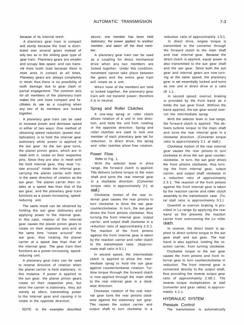
because of its internal teeth. A planetary gear train is compact
and sturdy because the load is distributed over several gears instead of only two as in the sliding gear type of gear train. Planetary gears are smaller and occupy less space; and can transmit more tooth load because there is more area in contact at al l times. Planetary gears are always completely in mesh; thus there is no possibility of tooth damage due to gear clash or partial engagement. The common axis for all members of the planetary train makes the unit more compact and facilitates its use as a coupling when any two of its members are locked together.
A planetary gear train can be used to increase power and decrease speed in either of two ways: One method of obtaining speed reduction (power multiplication) is to hold the internal gear stationary while power is applied to the sun gear. As the sun gear turns, the planet pinion gears, which are in mesh with it, rotate on their respective pins. Since they are also in mesh with the held internal gear, they must " rotate around" inside the infernal gear, carrying the planet carrier with them in the same direction of rotation as the sun gear. The planet carrier then rotates at a speed less than that of the sun gear, and the planetary gear train functions as a power-increasing, speed-reducing unit.
The same result can be obtained by holding the sun gear stationary and applying power to the internal gear. In this case, rotation of the internal gear causes the planet pinion gears to rotate on their respective pins and at the same time "rotate around" the sun gear, thus rotating the planet carrier at a speed less than that of the internal gear. The gear train then functions as a power-increasing, speed-reducing unit.
A planetary gear train can be used to reverse direction of rotation when the planet carrier is held stationary. In this instance, if power is applied to the sun gear, the planet pinion gears rotate on their respective pins; but since the carrier is stationary, they act merely as idlers, transmitting power to the internal gear and causing it to rotate in the opposite direction.
NOTE: In the examples described
AUTOMATIC TRANSMISSION
above, one member has been held stationary, the power applied to another member, and taken off the third member.
A planetary gear train can be used as a coupling for direct mechanical drive when any two members are locked together. Under this condition, movement cannot take place between the gears and the entire gear train wil l rotate as a unit.
When none of the members are held or locked together, the planetary gear train will not transmit power; therefore it is in neutral.
Sprag and Roller Clutches A one-way sprag or roller clutch
allows rotation of a unit in one direction, and locks the unit from rotating in the opposite direction. Sprag and roller clutches are used to lock one member of each planetary gear set for reduction. In direct drive, the sprag and roller clutches allow free rotation.
Power Flow Refer to Fig. 1. With the selector lever in drive
range, the forward clutch is applied. This delivers turbine torque to the main shaft and turns the rear internal gear in a clockwise direction. (Converter torque ratio is approximately 2:1 at stall.)
Clockwise motion of the rear internal gear causes the rear pinions to turn clockwise to drive the sun gear counterclockwise. In turn, the sun gear drives the front pinions clockwise, thus turning the front internal gear, output carrier, and output shaft clockwise in a reduction ratio of approximately 2.5:1. The reaction of the front pinions against the front internal gear is taken by the reaction carrier and roller clutch to the transmission case. (Approximate stall ratio is 5:1.)
In second speed, the intermediate clutch is applied to al low the intermediate sprag to hold the sun gear against counterclockwise rotation. Turbine torque through the forward clutch is now applied through the main shaft to the rear internal gear in a clock-wise direction.
Clockwise rotation of the rear internal gear turns the rear pinions clock-wise against the stationary sun gear. This causes the output carrier and output shaft to turn clockwise in a
7-3
reduction ratio of approximately 1.5:1. In direct drive, engine torque is
transmitted to the converter through the forward clutch to the main shaft and rear internal gear. Because the direct clutch is applied, equal power is also transmitted to the sun gear shaft and the sun gear. Since both the sun gear and internal gears are now turning at the same speed, the planetary gear is set essentially locked and turns as one unit in direct drive or a ratio
Of 1:1. In second speed, overrun braking
is provided by the front band as it holds the sun gear fixed. Without the band applied, the sun gear would overrun the intermediate sprag.
With the selector lever in low range, the forward clutch is applied. This delivers turbine torque to the main shaft and turns the rear internal gear in a clockwise direction. (Converter torque ratio is approximately 2:1 at stall.)
Clockwise motion of the rear internal gear causes the rear pinions to turn clockwise to drive the sun gear counter-clockwise. In turn, the sun gear drives the front pinions clockwise, thus turning the front internal gear, output carrier, and output shaft clockwise in a reduction ratio of approximately 2.5:1. The reaction of the front pinions against the front internal gear is taken by the reaction carrier and roller clutch assembly to the transmission case. (Total stall ratio is approximately 5:1.)
Downhill or overrun braking is provided in Lo range by applying the rear band as this prevents the reaction carrier from overrunning the Lo roller clutch.
In reverse, the direct clutch is applied to direct turbine torque to the sun gear shaft and sun gear. The rear band is also applied, holding the reaction carrier, from turning clockwise.
Clockwise torque to the sun gear causes the front pinions and front internal gear to turn counterclockwise in reduction. The front internal gear is connected directly to the output shaft, thus providing the reverse output gear ratio of approximately 2.08:1. The reverse torque multiplication at stall (converter and gear ratios) is approximately 4.1:1.
HYDRAULIC SYSTEM
Pressure Control The transmission is automatically

7-4 AUTOMATIC TRANSMISSION
controlled by a hydraulic system. Hydraulic pressure is supplied by the transmission gear-type oil pump, which is engine driven. Main line pressure is controlled by a pressure regulator valve train located in the pump. This regulator controls line pressure automatically, in response to a pressure signal from a modulator valve, in such a way that the torque requirements of the transmission are met and smooth shifts are obtained at al l throttle openings.
To control line pressure properly, a modulator pressure is used which varies in the same manner as torque input to the transmission. Since the converter torque output is the product of engine torque and converter ratio, modulator pressure must compensate for changes in either or both of these.
To meet these requirements, modulator pressure is regulated by engine vacuum which is an indicator of engine torque and carburetor opening. It is decreased by governor pressure with an increase in vehicle speed because converter torque ratio does the same.
Vacuum Modulator
The engine vacuum signal is provided by the vccuum modulator, consisting of an evacuated metal bellows, a diaphragm, and springs. These are so arranged that, when installed, the bellows and one spring apply a force which acts on the modulator valve to increase modulator pressure. Engine vacuum and the other spring act in the opposite direction to decrease modulator pressure, or low engine vacuum, high modulator pressure; high engine vacuum, low modulator pressure.
Governor Assembly The vehicle speed signal to the mod
ulator valve is supplied by the transmission governor, which is driven by the output shaft. The governor consists of two sets of flyweights, twc springs, and a regulator valve. Centrifugal force on the flyweights is imposed on the regulator valve, causing it to regulate a pressure signal that increases with increasing speed.
Centrifugal force is proportional to the square of vehicle speed. This means that a given change in vehicle speed results in a smaller change in
governor pressure at low speeds than at high speeds. Because of this characteristic, a governor with a single set of weights has less pressure change at low speed than at high speed. To increase the pressure change of the governor signal at low speeds, the flyweights are so designed that their effective mass is greater at speeds below approximately 720 rpm. than it is above this speed. This is done by arranging the primary weights so that they act through preloaded springs on the secondary weights, which in turn act on the valve. At approximately 720 rpm., the centrifugal force on each primary weight exceeds the spring force and the primary weights move to a grounded stop. With the primary weights grounded, the force on the governor regulator valve is equal to the spring forces plus the centrifugal force on the secondary weights.
Function of Valve and Hydraulic Control Units
The pressure regulator regulates line pressure according to a fixed spring force and forces controlled by modulator and reverse pressures. It controls the flow of oil that charges the torque converter, feeds the oi l cooler, and provides lubrication for the transmis-sion.
The manual valve establishes the range of transmission operation as selected by the vehicle operator through the manual selector lever.
The governor assembly generates a speed-sensitive oil pressure that increases with output shaft or vehicle speed. Governor pressure is used to vary the shift points and modulator pressure regulation.
The modulator valve regulates line pressure to a modulator pressure that varies with torque to the transmission. It senses forces created by vacuum modulator bellows that increase modulator pressure, by engine vacuum acting on a diaphragm to decrease modulator pressure, and by governor pressure which is generated by the governor assembly. Governor pressure tends to decrease modulator pressure.
The 1-2 shift valve controls the oil pressure that causes the transmission to shift from 1-2 or 2-1 . Its operation is controlled by governor pressure, detent pressure, modulator pressure, Lo oil pressure and a spring force.
The 1-2 regulator valve regulates modulator pressure to a pressure proportional to modulator pressure, tending to keep the 1-2 shift valve in the downshift position.
The 1-2 detent valve senses regulated modulator pressure tending to hold the 1-2 shift valve in the down-shift position and provides an area for detent pressure for detent 2-1 shifts.
The 2-3 shift valve controls the oil pressure that causes the transmission to shift from 2-3 or 3-2. Its operation is controlled by modulator, intermediate, governor and detent pressure as well as a spring force.
The 2-3 modulator valve senses modulator pressure to apply a variable force proportional to modulator pressure, which fends to hold the 2-3 shift valve downshifted.
The 3-2 valve shuts off modulator pressure from acting on the shift valve trains after the direct clutch has been applied. This allows fairly heavy throttle operation in third speed without downshifting. In third speed, modulator oil above 105 psi., or detent oil is directed to the shift valves to provide the downshift forces.
The 1-2 accumulator valve regulates drive pressure to a 1-2 accumulator pressure, which increases as modulator pressure increases to control the intermediate clutch pressure during the 1-2 shift. Detent and Lo oil pressures increase accumulator pressure.
The detent valve shifts when line oil is exhausted at the end of the valve when the detent solenoid is energized. This directs detent pressure to the 1-2 and 2-3 modulator valves, and also allows the detent regulator valve to regulate.
The detent regulator valve, when the detent valve shifts, is freed to allow drive oil to enter the detent passage, and thus becomes regulated to a value of 70 psi. Detent pressure will also flow into the modulator passage which flows to the shift valves. Lo oil moves the detent regulator open to drive oil allowing drive oil to enter the modulator and detent passages.
The rear servo and accumulator assembly serves three functions: (1) the band apply piston provides the band apply force to hold the rear band in reverse, (2) the band apply piston provides the band apply force for overrun band apply in Lo range first

gear, and (3) the accumulator piston, in conjunction with 1-2 accumulator oil, provides the accumulator function for the apply of the intermediate clutch.
The front servo serves two functions: (1) intermediate clutch oil applies the front servo to apply the front band in second Super and Lo range, and (2) during a 2-3 shift, direct clutch o i l utilizes the servo and accumulator pistons as the accumulator for direct clutch apply.
SERVO OPERATION
Front Servo
The front servo applies the second overrun band to provide engine braking in second gear in Super and Lo ranges. It is also used as an accumulator for the apply of the direct or third clutch and in conjunction with a series of check balls controlling orifices is a part of the timing for the release of the direct or third clutch.
To prevent the apply of the second overrun band in Neutral, Drive and Reverse ranges, oil is directed from the manual valve to the release side of the servo piston.
In drive range, the servo release oi l from the manual valve is used to charge the servo in preparation for the apply of the direct clutch.
Direct clutch oi l is directed to the front servo accumulator piston where spring force, plus third clutch pres-ures, stroke the piston up against the force of servo release oil. This lowers the clutch apply pressure for a smooth engagement.
The release of the direct clutch and the exhausting of the front servo accumulator is slowed down by three check balls and three orifices, which permits a soft return of the drive load to the intermediate Sprag and also allows engine rpm. to increase during a detent 3-2 downshift in preparation for the lower gear ratio, which results in a smooth shift and better acceleration.
Reverse — Neutral — Drive — First Speed
Servo oil from the manual valve in Drive range charges the accumulator by stroking the servo and accumulator pistons against the accumulator spring. This prepares the accumulator for the controlled apply of the direct clutch
A U T O M A T I C T R A N S M I S S I O N
on a 2-3 shift. The charging of the accumulator in Drive range, first gear, also makes it possible to have a controlled 1-3 "let up " shift as the accumulator is prepared for direct clutch apply in first gear.
Servo oil and the servo release spring prevent the apply of the band in second gear Drive range when intermediate clutch apply oil is directed between the servo and accumulator pistons.
Servo oil in Reverse and Neutral ranges is incidental.
Drive Range — Second Speed Servo oil charging the accumulator
is present in first and second gears and has the servo and accumulator pistons stroked against the accumulator spring.
In second gear, intermediate clutch oil is directed between the servo and accumulator pistons but does not separate the pistons; the force of servo oil holding the piston down is equal to the force in intermediate clutch oil attempting to stroke the servo piston.
Drive Range —Third Speed Direct clutch pressure rises to a value
such that the force from it, plus the accumulator spring force, overcomes the force from the servo pressure and moves the accumulator piston to the stop on the accumulator piston pin. This, in turn, strokes the servo piston the same amount of travel, which allows it to just contact the band-apply washer on the servo pin, but it will not move the pin and apply the band.
The stroking of the accumulator piston absorbs some direct clutch oil and permits the direct clutch to apply at reduced pressure for a smooth 2-3 shift.
Drive Range —3-2
The release of the direct clutch is softened by the front servo, three orifices, and three check balls to allow a smooth transfer of the drive load to the intermediate Sprag. The controlled release pressure lets the engine increase its rpm. during detent down-shifts to prepare for the lower gear ratio of second gear, which results in a smooth shift and better acceleration.
Servo oil seats a check bal l , intermediate clutch oil seats another check bal l , and oil must pass through the
7-5
two orifices which slows the stroking of the servo and accumulator pistons. The exhausting direct clutch oil from the accumulator and the direct clutch seats a third check bal l , and the exhausting direct clutch oil passes through an orifice which controls the clutch pressure during the direct clutch release.
Super Range — Second Speed Intermediate clutch oil from the 1-2
shift valve seats the check bal l , passes through an orifice, and applies the front band. The pressure applying the band is reduced by the action of the accumulator piston, which is moved by orificed flow of intermediate clutch oil and resisted by the accumulator spring and exhausting orificed direct clutch oil in a manual downshift 3-2 for a smooth apply of the band for Super range engine braking.
Rear Servo The rear servo applies the rear band
for overrun engine braking in Lo range first gear. It applies the band in Reverse to hold the reaction carrier to provide the reverse gear ratio.
On the 1-2 shift in Drive and Super ranges, it serves as an accumulator for the intermediate clutch to provide a smooth shift.
Drive — D-1 — First Speed In first gear Drive and Intermediate
ranges, 1-2 accumulator oil is directed to the rear servo accumulator piston in preparation for the 1-2 shift.
Drive — D-2 — Second Speed Intermediate clutch apply oil is d i
rected to the rear servo accumulator piston, stroking the piston against 1-2 accumulator oil and the accumulator spring. This action absorbs some intermediate clutch apply oil and permits the intermediate clutch to apply at reduced pressure for a smooth 1-2 shift.
Lo — First Speed Overrun engine braking in Lo range
first gear is provided for by the rear servo applying the band to hold the reaction carrier from clockwise rotation, viewed from front of the car.
The 1-2 accumulator oil is directed to the accumulator piston, which attempts to prevent the servo from applying. Lo range oil directed to the servo piston, which has the larger area, ap-

7-6 AUTOMATIC TRANSMISSION
plies the band. Because 1-2 accumulator oil is present, the force applying the band is lowered. This provides a smooth apply.
Lo —Second Speed In second gear, the rear band is re
leased. Intermediate clutch oil is d i rected to the release side of the servo piston which, with 1-2 accumulator o i l , balances out the Lo range oil on the apply side of the servo piston, and the servo release spring strokes the servo piston to the released position.
Reverse In reverse, the rear band is applied
to hold the reaction carrier. Reverse oil is directed to the servo piston to apply the band. To ensure the band holding the reaction carrier for the reverse gear ratio, line pressure is increased in Reverse and no other oil pressures are present in the servo to resist the apply of the servo piston.
1-2 Accumulator
The 1-2 accumulator oil charges the rear servo accumulator in first gear in preparation for the apply of the intermediate clutch on the 1-2 shift. The 1-2 accumulator oil pressure is used to obtain greater flexibility in attaining the desired curve for various engine requirements. Drive oi l is directed to the 1-2 accumulator valve and is regulated to become 1-2 accumulator oil. Modulator pressure is directed to the 1-2 accumulator valve. This results in 1-2 accumulator pressure being engine-torque conscious, and adjusts for smooth, durable shifts according to engine-torque output.
Detent oil is directed to the 1-2 accumulator valve to raise 1-2 accumulator pressure during detent 1-2 shifts for clutch durability. Lo range oil is directed to the 1-2 accumulator valve during Lo range operation to raise 1-2 accumulator pressure to line pressure; this increased pressure, directed to the rear servo accumulator piston, resists servo apply pressure and slows down the apply of the rear band for a smooth manual shift to Lo range first gear, or for a 2-1 shift in Lo range.
DETENT A N D DETENT
REGULATOR VALVES
When the accelerator pedal is de-
pressed al l the way to the floor, the detent valve train replaces the modulator as a controller of shift points. Line pressure is fed through a small orifice to one end of the detent valve. In normal throttle operation, the cavity at this end of the valve is sealed by a needle valve in the detent solenoid assembly. This line pressure holds the detent valve train in an inoperative or normal position.
When the throttle is opened wide, an electric switch on the carburetor is closed, energizing the detent solenoid. The needle valve is opened by the solenoid, causing a pressure drop on the end of the detent valve. The detent regulator valve spring then shifts the detent valve, and causes the detent regulator to regulate detent oil to a fixed pressure of approximately 60 psi. When the detent valve shifts, it routes this fixed or detent pressure into the modulator passages. The detent valve train also routes detent pressure into the detent passages to the shift valve train. The detent upshift points are controlled by detent pressure in the modulator passages, and the detent downshifts by detent pressure in the detent passages. The shift points are fixed at relatively high speeds.
Detent pressure is directed to the 1-2 accumulator valve to increase 1-2 accumulator pressure for clutch durability during detent shifting. Detent pressure is directed to the modulator valve to prevent modulator pressure from dropping below approximately 60 psi. which, in turn, prevents line pressure from dropping below approximately 105 psi.
In Lo range operation, Lo oil is d i rected to the detent regulator valve and spacer, the spring then moves the detent and regulator valves to the opposite end of the valve bore. Lo oil is also directed to the detent regulator valve, to passage which is used as an exhaust when the valve is regulating. Lo oil in these two areas prevents the detent valve from regulating, and drive oil passes through the detent regulator valve into the detent and modulator passages at Lo range pressure of 150 psi. This increase in detent and modulator pressures will downshift the 1-2 valve at speeds below approximately 40 mph., and will prevent the transmission from upshifting out of first gear regardless of vehicle speed.
TRANSMISSION LINKAGE ADJUSTMENT
The adjustment on vehicles equipped with automatic transmission is accomplished by adjusting the length of the shift rod, with the transmission shift lever and selector lever in their neutral positions. Procedure for making the adjustment is given below:
Remove the cotter pin, flat washer and spring washer from the adjusting block at the transmission end of the shift rod, and remove the block from the shift lever.
Make sure the transmission shift lever is in the neutral detent position.
Place the selector lever in the neutral position and hold it firmly forward against the stop.
Loosen the lock nuts at either end of the adjusting block, and position the block on the shift rod so it may be freely inserted on the transmission shift lever without moving the lever. Tighten the nuts to 6-12 Foot Pounds torque.
Operate selector lever to be sure transmission detents are engaging in their respective positions.
ROAD TEST
Shift Pattern Check
DRIVE RANGE: Position selector lever in DRIVE
RANGE and accelerate the vehicle from 0 MPH. A 1-2 and 2-3 shift should occur at all throttle openings. (The shift points will vary with the throttle opening). As the vehicle decreases in speed to 0 MPH, and 3-2 and 2-1 shifts should occur.
INTERMEDIATE RANGE: Position the selector lever in INTER
MEDIATE RANGE and accelerate the vehicle from 0 MPH. A 1-2 shift should occur at all throttle openings. (No. 2-3 shift can be obtained in this range). The 1-2 shift point will vary with throttle opening. As the vehicle decreases in speed to 0 MPH, a 2-1 shift should occur. NOTE: The 1-2 shift in INTERMEDIATE RANGE is somewhat firmer than in DRIVE RANGE. This is normal.
LO RANGE: Position the selector lever in LO
RANGE and accelerate the vehicle from 0 MPH. No upshift should occur in this range, except in some vehicles

A U T O M A T I C T R A N S M I S S I O N 7 -7
which have a high numerical axle ratio and/or high engine RPM.
2ND GEAR - OVERRUN BRAKING: Position the selector in DRIVE
RANGE, and with the vehicle speed at approximately 35 MPH, move the selector lever in INTERMEDIATE RANGE. The transmission should downshift to 2nd. An increase in engine RPM and an engine braking effect should be noticed. Line pressure should change
from approximately 70 PSI to approximately 150 PSI in 2nd.
1ST GEAR - OVERRUN BRAKING: Position the selector lever in INTER
MEDIATE RANGE at approximately 30 to 40 MPH, with throttle closed, move the selector lever to Lo. A 2-1 downshift should occur in the speed range of approximately 40 to 20 MPH, depending on axle ratio and valve body cali-
bration. The 2-1 downshift at closed throttle will be accompanied by increased engine RPM and an engine braking effect should be noticed. Line pressure should be approximately 150 PSI. Stop vehicle.
REVERSE RANGE: Position the selector lever in REVERSE
POSITION and check for reverse operation.
Check Oil Pr
Range
Drive — Brakes Applied Engine at 1000 RPM
Super or Lo — Brakes Applied Engine at 1000 RPM
Reverse — Brakes Applied Engine at 1000 RPM
Neutral — Brakes Applied Engine At 1000 RPM
Drive Idle Set Engine Idle To Specifications
Drive - 30 MPH Closed Throttle or On Hoist*
essures In Following Manner
Oil Pressure Normal P.S.I.
60 TO 90
135 TO 160
95 TO 150
55 TO 70
60 TO 85
55 TO 70
*The Drive-30 MPH closed throttle pressure reading may be taken during a road test or: 1. Vehicle on hoist — driving wheels off ground, foot off brake, in drive range. 2. Engine 2000 rpm. 3. Close throttle (foot off accelerator) and take pressure reading engine 2000-1200
rpm.
NOTE: With closed throttle and driving wheels off the ground, engine RPM will drop rapidly. Pressure reading must be taken within RPM's indicated and with closed throttle.

TRANSMISSION MALFUNCTION RELATED TO OIL PRESSURE
(Pressures Obtained By The Preliminary Checking Procedure on Page 7)
Malfunction
No 1-2 Upshift and/or Delayed Upshift
Slipping — Reverse
Slipping — 1st Gear
Downshift With Zero Throttle and No Engine Braking In Drive
Drive Brakes
Applied 1000 RPM
Oil Pressure
Normal
Normal
High
High
Normal
Low
Normal
Reverse Brakes
Applied 1000 RPM
Oil
Pressure
Normal
Normal
Normal
High
Low
Normal
Normal
Super or Lo Brakes
Applied 1000 RPM
Oil Pressure
Normal
Normal
Normal
Normal
Normal
Low to Normal
Normal
Neutral Brakes
Applied 1000 RPM
Oil Pressure
Normal
Normal
Normal
High
Normal
Normal
Normal
Drive 30MPH Closed Throttle
Oil Pressure
Normal
Normal
High
-
Normal
Low to Normal
High
Drive Idle
Oil Pressure
Normal
Normal
-
-
-
—
High
Pressure Drop Occurs While Engine RPM
Increases From 1000 to 3000 RPM
Wheels Free To Move**
Drop
No Drop
-
-
-
-
-
Possible Cause of Malfunction
Malfunction in Control Valve Assy.
Malfunction in Governor or Governor Feed System
Malfunction in Detent System
Malfunction in Modulator or Vacuum Feed System to Modulator
Oi l Leak in Feed System to The Direct Clutch
Oi l Leak in Feed System to The Forward Clutch
Stator and Detent Wires Switched
*Drive Range, Vacuum Line Disconnected To Modulator.

AUTOMATIC TRANSMISSION 7-9
NO 1-2 UPSHIFT AND/OR DELAYED UPSHIFT OR 1-2 & 2-3 UPSHIFT-FULL THROTTLE ONLY
Check for vacuum leaks or no vacuum. See page 16.


AUTOMATIC TRANSMISSION 7-11

7-12 AUTOMATIC TRANSMISSION

A U T O M A T I C T R A N S M I S S I O N 7 -13
DRIVE IN NEUTRAL
Check outside manual linkage & correct. Page 16.
- INTERNAL LINKAGE -Manual valve disconnected or end broken, inside detent lever pin broken.
- PUMP ASSEMBLY -Trans, lube pressure leaking into forward clutch apply passage.
- FORWARD CLUTCH -Burned plates — check cause — page 15.
Incorrect clutch plate usage — see page 3 1 .
W O N T HOLD IN PARK OR W O N T RELEASE FROM PARK
Check outside manual linkage & correct.
Page 16.
- INTERNAL LINKAGE -1. Parking brake rod assy. (Check actuator
for chamfer). 2. Parking pawl broken, chamfer omitted. 3. Parking brake bracket loose, burr or
rough edges, or incorrectly installed. 4. Parking pawl return spring missing,
broken or incorrectly hooked.

7-14 AUTOMATIC TRANSMISSION
CAUTION: Before checking transmission for what is believed to be "trans, noise," make certain the noise is not from the water pump, alternator, air conditioner, power steering, etc. These components can be isolated by removing the proper belt and running the engine not more than two minutes at one time.
*There is no approved way of checking or cleaning the filter. If fhe filter is suspected of
being plugged or restricted, it must be replaced.

AUTOMATIC TRANSMISSION 7-15
DIAGNOSIS GUIDES
Causes of Oil Leaks
Transmission Oil Pan Leaks Attaching bolts not correctly torqued. Improperly installed or damaged
pan gasket. Oil pan gasket mounting face not
flat.
Case Extension Leak
Attaching bolts not correctly torqued. Rear seal assembly — damaged or
improperly installed. (Propeller shaft yoke damaged).
Gasket or seal — (extension to case) damaged or improperly installed.
Porous casting. ' 0 " ring on output shaft damaged
(oil leak at yoke).
Case Leak
Filler pipe " O " ring seal damaged or missing; misposition of filler pipe bracket to engine — " loading" one side of the "O" ring.
Modulator assembly " O " ring seal — damaged or improperly installed.
Connector " O " ring seal — damaged or improperly installed.
Governor cover, gasket and bolts
— damaged, loose; case face damaged or porosity.
Leak at speedometer driven gear housing or seal. Leak at speedo hole plug.
Manual shaft seal — damaged, improperly installed.
Line pressure top plug — stripped, shy sealer compound.
Vent pipe. Porous case, or crocked at pressure
plug boss.
Front End Leak
Front seal — damaged (check converter neck for nicks, etc., also for pump bushing moved forward) garter spring missing.
Pump attaching bolts, and seals — damaged, missing, bolts loose.
Converter — leak in weld. Pump " O " ring seal — damaged.
(Also check pump oil ring groove and case bore).
Porous casting (pump or case). Pump — drain back hole not open.
Oil comes out vent pipe
Transmission over-filled — see page 15.
Water in oi l . Filter " O " ring damaged or im
properly assembled causing oil to foam.
Foreign material between pump and case or between pump cover and body, or variable stator solenoid screws too long — holding pump halves apart.
Case — porous, pump face improperly machined.
Pump — shy of stock, porous. Pump to case gasket mispositioned. Pump breather hole blocked or miss
ing. Hole in intake pipe. Check bol l in forward clutch housing
stuck open or missing.
Oil Cooler Lines
Connections at radiator loose or
stripped. Connections at case loose or
stripped.
Modulator Assy.
Diaphragm defective (See page 17).
Causes of Burned Clutch Plates
Forward Clutch
Check ball in clutch housing damaged, stuck or missing.
Clutch piston cracked, seals damaged or missing.
Low line pressure (see page 16). Manual valve mispositioned. Restricted oi l feed to forward clutch
(examples: clutch housing to inner and outer areas not dri l led, restricted or porosity in pump).
Pump cover oil seal rings missing, broken or undersize,- ring groove oversize.
Case valve body face not flat or porosity between channels.
Manual valve bent and center land not ground properly.
Intermediate Clutch
Constant bleed orifice in center support missing.
Rear accumulator piston oil ring, damaged or missing.
1-2 accumulator valve stuck in control valve assembly.
Intermediate clutch piston seals damaged or missing.
Center support bolt loose.
Low line pressure (See page 16). Intermediate clutch plug in case miss
ing. Case valve body face not flat or
porosity between channels. Manual valve bent and center land
not ground properly.
Direct Clutch
Restricted orifice in vacuum line to modulator (poor vccuum response).
Check ball in direct clutch piston damaged, stuck or missing.
Defective modulator bellows (see page 17).
Center support bolt loose. (Bolt may be tight in support but not holding support tight to case).
Center support oil rings or grooves damaged or missing.
Clutch piston seals damaged or missing.
Front and rear servo pistons and seals damaged.
Manual valve bent and center land not cleaned up.
Case valve body face not flat or porosity between channels.
Intermediate sprag clutch installed backwards.
3-2 valve, 3-2 spring or 3-2 spacer pin installed in the wrong sequence in 3-2 valve bore.
Incorrect combination of front servo and accumulator parts.
NOTE; If direct clutch plates and front band are burned, check manual linkage (see page 16).
NOTE: Burned clutch plates can be caused by incorrect usage of clutch plates. Also, anti-freeze in transmission fluid can cause severe damage, such as large pieces of composition clutch plate material peeling off.
Checking Transmission Oil Level
1. Engine Running. 2. Vehicle on Level Surface. 3. Brakes Applied.

7-16 AUTOMATIC TRANSMISSION
4. Move Lever Through Al l Ranges. 5. Place Transmission in "Park." 6. Check Oil Level. 7. If Oil Is Low, Check for Possible
Causes — Refer to Page 15.
The oil level should be between the " a d d " and " f u l l " marks at normal operating temperature (170°F.). This temperature is obtained after at least 15 miles of expressway driving or equivalent city driving. Also, at normal operating temperature, the oil will heat the gauge end of the dip stick to a degree where the average person can not grasp it firmly with his bare hand without discomfort.
If the transmission is not at operating temperature, the oil level should be approximately 1/4" below the " a d d " mark with the oil at approximately 75° F. (room temperature.) If the oil level is correctly established at room temperature (75°F), it should be at the " fu l l " mark on the dip stick when the transmission reaches normal operating temperature (170°F.).
CAUTION: Do not overfill transmission, as this will cause foaming and loss of oil through the vent pipe.
Manual Linkage Adjustment
The transmission manual linkage must be adjusted so that the pointer on the indicator quadrant and linkage detents or stops corresponds with the transmission inside detent lever detents. If the linkage is not adjusted properly, an internal leak could occur at the manual valve which could cause a clutch and/or front band failure.
Cause of Low Line Pressure
Low Transmission Oil Level
Modulator Assembly — See Page 17.
Filter
Blocked or restricted. " O " ring on intake pipe and/or
grommet omitted or damaged. Split or leaking intake pipe. Wrong filter assembly.
Pump
Pressure regulator or boost valve stuck.
Gear clearance, damaged, worn (pump will become damaged if drive gear is installed backwards, or if converter pilot does not enter crankshaft freely).
Pressure regulator spring, too weak. Not enough spacers in pressure reg
ulator. Pump to case gasket mispositioned. Defective pump body and/or cover. Mismatch pump cover/pump body.
Internal Circuit Leaks
Forward clutch leak (pressure normal in neutral and reverse — pressure low in drive).
Check pump rings.
Check forward clutch seals. Direct clutch leak (pressure normal
in neutral, low, int. and drive — pressure low in reverse).
Check center support oil seal rings. Check direct clutch outer seal for damage. Check rear servo and front accum. pistons and rings for damage or missing.
Case Assembly
Porosity in intake bore area. Check case for intermediate clutch
plug leak or blown out. Lo-reverse check ball mispositioned
or missing (this will cause no reverse and no overrun braking in lo range).
There is no approved way of check-ing or cleaning the filter. If the filter is suspected of being plugged or restricted, it must be replaced.
Causes of High Line Pressure
Vacuum Leak
Full leak, vacuum line disconnected. Partial leak in line from engine to
modulator. Improper engine vacuum. Vacuum operated accessory leak.
(Hoses, vacuum advance, etc.)
Damaged Modulator
Stuck valve. Wafer in modulator. Not operating properly. — See page
17.
Detent System
Detent switch actuated (Plunger stuck) or shorted.
Detent wiring shorted. Detent solenoid stuck open. Detent feed orifice in spacer plate
blocked. Detent solenoid loose. Detent valve bore plug damaged. Detent reg. valve pin short.
Pump
Pressure reg. and/or boost valve stuck.
Incorrect pressure reg. spring or valve.
Too many pressure reg. valve spacers.
Pump casting bad. Pressure boost valve installed back
wards or defective. Aluminum bore plug has hole or
otherwise defective. Pressure boost bushing broken or
otherwise defective.
Control Valve Assembly
Control valve assy, to spacer gasket off location.
Gaskets installed in reverse order.
Causes of Improper Vacuum At Modulator
Engine
Tune up. Loose vacuum fittings. Vacuum operated accessory leak
(hoses, vacuum advance, etc). Engine exhaust system restricted.
Vacuum Line To Modulator
Leak. Loose fitting. Restricted orifice, or incorrect orifice
size.
Carbon build up at mod. vac. fitting. Pinched line. Grease in pipe (no or delayed up
shift-cold).
Control Valve Assembly — Governor Line Pressure Check
1. Install Line Pressure Gage

AUTOMATIC TRANSMISSION 7-17
2. Disconnect Vacuum Line to Modulator
3. With Car on Hoist (Rear Wheels, Off Ground), Foot Off Brake, In Drive, Check Line Pressure At 1000 RPM.
4. Slowly Increase Engine RPM to 3000 RPM and Determine If A Line Pressure Drop Occurs (7 PSI or More)
5. If Pressure Drop Occurs, Disassemble, Clean and Inspect Control Valve Assembly.
6. If No Pressure Drop Occurs:
Inspect governor.
Stuck valve. Weight freeness. Restricted orifice in governor valve.
Governor feed system. Check screen in control valve assembly or case. Check for restrictions in governor pipe.
Modulator Assembly Diagnosis Procedure
Vacuum Diaphragm Leak Check
Insert a pipe cleaner into the vacuum connector pipe as far as possible and check for the presence of transmission oi l . If oil is found, replace the modulator. Transmission oil may be lost through diaphragm and burned in engine.
NOTE: Gasoline or water condensation may settle in the vacuum side of the modulator. If this is found without the presence of oil the modulator should not be changed.
Atmospheric Leak Check
Apply a liberal coating of soap bubble solution (obtainable at a 5c-10c store) to the vacuum connector pipe seam, the crimped upper to lower housing seam, and the threaded screw seal. Using a short piece of rubber tubing, apply air pressure to the vacuum pipe by blowing into the tube and observe for leak bubbles. If bubbles appear, replace the modulator.
NOTE.- Do not use any method other than human lung power for applying air pressure, as pressures over 6 PSI may damage the modulator.
MINOR MAINTENANCE AND ADJUSTMENTS
Services outlined below can be performed without removing the transmission from the vehicle. Complete procedures are not given for al l of these services, since they are covered in detail under disassembly and reassembly.
Neutralizer Switch Adjustment
The neutralizer switch must be adjusted so that the vehicle will start in the park or neutral position, but will not start in the other positions.
Pressure Regulator Valve Removal
Raise vehicle on hoist or place on jack stands. Provide container to catch oil.
Remove bottom pan and gasket. Drain oi l .
Remove the oil filter retaining bolt and lift out pump intake pipe and oil filter assembly.
Remove and discard intake pipe O-ring and bottom pan gasket.
Using a screwdriver or steel rod, compress regulator boost valve bushing against pressure regulator spring.
CAUTION: Pressure regulator spring is under extreme pressure and will force valve bushing out of bore when snap ring is removed if valve bushing is not held securely.
Continue to exert pressure on valve bushing and remove snap ring, using snap ring pliers. Gradually release pressure on valve bushing until all spring force is exhausted.
Carefully remove regulator boost valve bushing and valve, and pressure regulator spring. Be careful not to drop parts, as they will fal l out if they are not held.
Remove pressure regulator valve and sprirg retainer. Remove spacers if present. Be careful not to drop pressure regulator valve when removing it from bore.
Pressure Regulator Valve Installation
Install spring retainer on pressure regulator spring. Also install spacers if previously removed.
Install pressure regulator valve on spring, stem end first.
Install boost valve into bushing, stem end out, and stack parts so that pressure regulator spring is against valve bushing.
Install complete assembly into pressure regulator valve bore, being careful not to drop parts during installation.
Using a screwdriver or steel rod, compress regulator boost valve bushing against pressure regulator spring until it is beyond snap ring groove, and install snap ring using snap ring pliers.
NOTE: To facilitate installation of snap ring, encircle it around screwdriver or steel rod, compress tangs with snap ring pliers, and slide snap ring upward into ring groove in valve bore.
Install new intake pipe O-ring onto intake pipe and install pipe and oil filter assembly into transmission case bore, retaining oil filter with retainer bolt.
Install new gasket on bottom pan and install bottom pan.
Install thirteen bottom pan attaching screws. Tighten screws to 10-13 Foot Pounds.
Lower vehicle to floor and add fluid to transmission as required.
Control Valve Body Removal Remove bottom pan and oil filter. Remove and discard intake pipe O-
ring and pan gaskets. Disconnect solenoid lead from con
nector terminal. Remove control valve body attach
ing screws and detent roller spring assembly.
NOTE: Do not remove solenoid attaching screws.
Remove control valve body assembly and governor pipes. If care is taken in removing control valve body, the six (6) check balls will stay in place above the spacer plate.
CAUTION: Do not drop manual valve.
Remove the governor pipes and manual valve from control valve body.
Remove and discard control valve assembly to spacer gasket.
Control Valve Body Installation
Installation of the control valve body

7-18 AUTOMATIC TRANSMISSION
is the reverse of the removal, using new control valve assembly to spacer gasket, intake pipe "O" ring and pan gasket. Refill, adding oil as required.
Governor Removal
Remove governor cover attaching screws, cover and gasket.
Discard gasket. Withdraw governor assembly from
case.
Governor Installation
Installation of the governor assembly is the reverse of the removal. Use a new gasket under the governor cover. Refill, adding oil as required.
Modulator and Modulator Valve Removal
Remove modulator assembly attaching screw and retainer.
Remove modulator assembly from case. Discard O-ring seal.
Remove modulator valve from case.
Modulator and Modulator Valve Installation
Installation of the modulator assembly and modulator valve is the reverse of the removal. Use a new O-ring seal on the modulator assembly. Refill adding oil as required.
Parking Linkage Removal
Remove bottom pan and oil filter. Discard gasket.
NOTE: It will not be necessary to replace the converter assembly when a transmission failure has occurred, unless converter is defective. However, it is Still recommended that the transmission is properly cleaned, the oil filter replaced, cooler and cooler lines flushed out after any failure that generates sludge or dirt.
Torque Converter Removal
With transmission in cradle on portable jack, remove torque converter assembly from transmission case by pulling straight out.
NOTE: Converter contains a large amount of oil.
Unthread jam nut holding detent lever to manual shaft.
Remove manual shaft retaining pin from case.
Remove manual shaft and jam nut from case.
Remove parking actuator rod and detent lever assembly.
Remove parking pawl bracket attaching screws and bracket.
Remove parking pawl return spring. Remove parking pawl shaft retainer. Remove cup plug, parking pawl
shaft, and parking pawl.
Parking Linkage Installation
Installation of the parking linkage is the reverse of the removal. Use new seals and gasket. Refill, adding oil as required.
NOTE: As a normal maintenance procedure it is recommended that the manual shaft be lubricated with oil at the point where it enters the transmission case.
T R A N S M I S S I O N R E M O V A L
A N D I N S T A L L A T I O N
Removal Remove dipstick tube to engine bolt. Remove carpet trim ring. Remove top cover and lever on
transfer case. Mark and remove rear propeller
shaft. Remove exhaust pipe clamp bolt,
shift lever, down shift wire and speedometer cable.
DISASSEMBLY
72819
FIGURE 4 — Transmission in Holding
Fixture J-8763-01
Holding Fixture and Tool Base Installation
Install Holding Fixture J-8763 on
Position transmission jack and remove rear crossmember.
Remove exhaust pipe. Mark and remove front propeller
shaft at transfer case end. Remove oil cooler lines and vacuum
line. Remove converter housing splash
pan. Remove converter to flywheel bolts
and mark the converter and flywheel for alignment during installation.
Remove converter housing to engine bolts and remove transmission.
Installation
Install transmission and install engine bolts.
Install converter to flywheel bolts, making sure the mark made during removal is in alignment.
Install converter front splash pan. Install oil cooler lines and vacuum
line. Install front propeller shaft. Install exhaust pipe DO NOT
TIGHTEN. Install crossmember and remove
transmission jack. Tighten exhaust pipe. Install exhaust pipe clamp bolt, shift
lever, speedometer cable and down shift wire.
Install rear propeller shaft. Install top cover and shift lever on
transfer case. Install carpet trim ring. Install dip stick tube to engine bolt.
transmission case so that modulator assembly will be located on side of holding fixture nearest bench.
NOTE: Do not over-torque holding screw. This will bind center support.
Install fixture and transmission into Holding Tool Base J-3289-20 with bottom pan of transmission case facing upward, as shown in Figure 4.
Remove modulator assembly, attaching screw and retainer from transmission case.
Remove modulator assembly and O-ring seal from adapter. Remove adapter from transmission case.
Remove modulator valve from transmission case.

Governor, Oil Pan, Oil Filter and Intake Pipe Removal
Remove attaching screws, governor cover and gasket from transmission case. Discard gasket, (Fig. 5).
FIGURE 5 — Removing Governor Cover Attaching Screw
Withdraw governor assembly from case.
Remove bottom pan and gasket from transmissions case. Discard gasket, (Fig. 6).
FIGURE 6 — Removing Transmission Oil Pan
Remove oil filter retainer bolt (Fig. 7).
Remove oil filter assembly from transmission case (Fig. 7).
FIGURE 7 — Removing-lnstalling Oil Filter
AUTOMATIC TRANSMISSION
Remove intake pipe-to-case O-ring from intake pipe or case. Discard "O" ring.
Control Valve Assembly, Solenoid Connector, Governor Pipes, and Detent Spring Assembly Removal
Remove attaching screws of control valve body and detent roller spring assembly from transmission case, as shown in Figure 8.
FIGURE 8 — Removing-lnstalling Detent Roller and Spring Assembly
Disconnect solenoid lead from connector terminal.
Remove control valve body assembly and governor pipes from transmission case (Fig. 9).
FIGURE 9 — Removing Control Valve Assembly and Governor Pipes
CAUTION: Do not drop manual valve.
Remove governor pipes from control valve assembly.
Remove control valve assembly to spacer gasket.
7-19
Rear Servo Removal
Remove rear servo cover attaching screws, servo cover and gasket from transmission case. Discard gasket (Fig. 10).
FIGURE 10 — Removing-lnstalling Rear Servo Cover
Remove rear servo assembly from transmission case, as shown in Figure 11.
72827
FIGURE 11 — Removing-lnstalling Rear Servo Assembly
Remove rear servo accumulator spring from transmission case.
Selection of Rear Band-Apply Pin
Attach Fixtures J-21370-5 and J-21370-6 to transmission case by

7-20 AUTOMATIC TRANSMISSION
means of rear servo assembly attaching screws, as shown in Figure 12. These fixtures will be used to select a band-apply pin. One of three lengths of band-apply pin must be selected, to adjust operation of rear servo.
Detent Solenoid
FIGURE 12 - Checking Apply Pin of Rear Band
Apply 25 Foot Pounds torque, then select proper length of band-apply pin (to be used during assembly of transmission) as follows: If both steps of J-21370-5 pin fixture are below the gauge surface, select long pin, identified by three rings; if the gauge surface is between the steps, select medium pin, identified by two rings; if both steps are above the gauge surface, select short pin, identified by one ring. Identification ring is located on band lug end of the pin.
Detent Solenoid, Control Valve Spacer, and Front Servo Removal
Remove solenoid attaching screws, detent solenoid assembly, and gasket from transmission case. Discard gasket (Fig. 13).
Withdraw detent solenoid case sleeve connector and O-ring seal from transmission case, as shown in Figure 14.
Remove control valve assembly spacer plate and gasket.
Remove six (6) check balls from cored passages in transmission case. Refer to Figure 15.
Remove front servo piston, washer, pin, retainer, and spring from transmission case, as shown in Figure 16.
Gasket
FIGURE 13 — Removing-lnstalling Detent Solenoid Assembly and Gasket
FIGURE 14 —Removing-lnstalling Case Connector Sleeve and "0" -Ring
Seal
Check Balls • ' " 72831
FIGURE 15 - Location of Check Balls
Servo Piston
Servo Pin
Spring Retainer
Servo Spring
Rear Oil Seal and Extension Housing Removal
Remove snap ring from output shaft sleeve. Remove gear. Remove output shaft sleeve-to-bearinc snap ring. Remove output shaft sleeve from bearing. Remove bearing-to-case extension snap ring and remove bearing. Remove the two seals if necessary. Refer to Figure 17.
Inspect sleeve, splines, and snap ring groove for damage. Inspect bearing.
Front Unit End Play
Remove one front pump attaching bolt and washer from either 5 or 10 o'clock position.
Install a 5/16-18 threaded slide hammer bolt, into bolt hole.
Mount a dial indicator on rod, then index indicator to register with end of turbine shaft, as shown in Figure 18.
Push turbine shaft rearward. Push output shaft forward. Set dial indicator to zero. Pull turbine shaft forward. Read resulting travel, or end play,
which should be .003"-.024". Selective washer controlling this end
play is the thrust washer, located between pump cover and forward clutch housing. If more or less washer thickness is required to bring end play within specifications, select proper washer from the following chart:
060-.064 .071-075 082-.086 093-.097 .104-. 108 115-.119 .126-. 130
Yellow Blue Red Brown Green Black Purple
FIGURE 16 — Removing-lnstalling Front Servo Piston
NOTE: An oil soaked washer may tend to discolor, so it will be necessary to measure washer lor its actual thickness.
Oil Pump, Forward Clutch, Turbine Shaft, and Direct Clutch Removal
If necessary to replace, pry front seal from oil pump (Fig. 19).
Remove pump attaching bolts and bolt washers.
Install 5/16"-'8 threaded slide hammers, into threaded holes in pump

AUTOMATIC TRANSMISSION 7-21
Output Shaft Sleeve
Rear O i l Seal Assembly
Snap Rings
Ball Bearing Assembly "0 " -R ing Case Extension Assembly
FIGURE 17 —Extension Housing Assembly
FIGURE 18 - Front Unit End Play
FIGURE 19 — Removing Front Seal
body at 5 and 10 o'clock positions. Remove pump assembly from case (Fig. 20)..
Remove and discard pump-to-case seal ring and gasket from oil pump.
Remove forward clutch assembly and turbine shaft from transmission case, as shown in Figure 2 1 .
Remove forward clutch hub to direct clutch housing thrust washer, if it did not come out with forward clutch housing assembly.
FIGURE 20 — Removing Oil Pump Assembly
FIGURE 21 — Removing-lnstalling Forward Clutch Assembly
Remove direct clutch assembly from transmission case (Fig. 22).
Manual Linkage Removal
Unthread jam nut holding detent lever to manual shaft.
FIGURE 22 — Removing-lnstalling Direct Clutch Assembly
Remove manual shaft retaining pin from transmission case, as shown in Figure 23.
Manual Shaft
FIGURE 23 - Manual Shaft and Retaining Pin
CAUTION: Do not lose jam nut as it becomes free from manual shaft.
Remove jam nut from manual shaft, then remove manual shaft and seal from transmission case.
Remove parking actuator rod and detent lever assembly from transmission case.
Remove attaching screws and parking bracket from transmission case (Fig. 24).
Remove parking pawl return spring from pawl and transmission case, as shown in Figure 25.
Remove retainer spring from parking pawl shaft (Fig. 26).
Remove parking pawl shaft cup plug, parking pawl shaft, and the parking pawl from transmission (Fig. 27).
Front Band Assembly and Sun Gear Shaft Removal
Remove front band assembly from

7-22 AUTOMATIC TRANSMISSION
Parking Brake
Bracket
Parking Brake Pawl
FIGURE 24 — Removing Parking Bracket
Return Spring Parking Pawl
FIGURE 25 — Removing-lnstalling Return Spring From Parking Brake
Pawl
FIGURE 26 — Removing-lnstalling Retainer Spring From Parking
Pawl Shaft
transmission cose (Fig. 28). Remove sun gear shaft as shown in
Figure 29.
Rear End Play Check
Install Slide Hammer Tool C-3752 into an extension housing attaching bolt hole.
Mount the Dial Indicator on the rod and index with the end of the output shaft (Fig. 30).
72845
FIGURE 27 — Removing-lnstalling Parking Brake Pawl and Pawl Shaft
FIGURE 28 — Removing-lnstalling Front Band Assembly
FIGURE 29 — Removing Sun Gear Shaft
Apply air pressure to apply the intermediate clutch (center oil passage) while moving the output shaft in and out to read the end play. End play should be from .007"-.019". The selective washer controlling this end play is the steel washer having 3 lugs that is located between the thrust washer and the rear face of the transmission case.
72843
FIGURE 30 - Rear Unit End Play
If a different washer thickness is required to bring the end play within specification, it can be selected from the following chart.
Notches and/or Thickness .074-.078 .082-.086 .090-.094 .098-. 102 .106-.110 .114-.118
Numeral None 1 Tab Side 2 Tabs Side 1 Tab O.D. 2 Tabs O.D. 3 Tabs O.D.
1 2 3 4 5 6
Intermediate Clutch Removal Remove bolt which secures center
support to case, using a 3/8" 12-point thin wall deep socket (Fig. 31).
Remove intermediate clutch backing plate to case snap ring.
Remove intermediate clutch backing plate, three (3) composition, and three (3) steel clutch plates from transmission case (Fig. 32).
FIGURE 31 — Removing Center Support Bolt

AUTOMATIC TRANSMISSION 7-23
FIGURE 32 - Intermediate Clutch
Center Support, Gear Unit Assembly, Support to Case Spacer and Rear Band Assembly Removal
Remove center support to cose snap ring as shown in Figure 33.
Remove entire gear unit assembly from transmission case by lifting with Gear Assembly installing and Removing Tool J-21795, with Slide Hammer J-6125-1 (Fig. 34).
Remove output shaft-to-case thrust washer from rear of output shaft or inside case.
Place gear unit assembly, with output shaft facing down, in work bench hole and Holding Fixture J-21364.
Gear Unit Disassembly
Remove case center support assembly from gear unit assembly (Fig. 37).
FIGURE 37 — Removing Center Support From Gear Unit
Remove thrust washer which is normally between center support and re-
FIGURE 33 - Removing Center Support Snap Ring
FIGURE 34 — Removing Center Support and Gear Unit
Remove rear unit selective washer from transmission case, as in Figure 35.
SUB-ASSEMBLY OVERHAUL
action carrier, as shown in Figure 38. Remove center support-to-sun gear
races and thrust bearing.
Bleed Orif ice 72854
FIGURE 38 — Removing-lnstalling Center Support Thrust Washer
Remove support to case spacer ring (Fig. 35).
Remove rear band assembly from transmission case (Fig. 36).
FIGURE 35 - Selective Washer and Spacer Ring
72852
FIGURE 36 — Removing Rear Band
NOTE: One race may have been removed with center support.
Remove reaction carrier and roller clutch assembly from output carrier assembly, as shown in Figure 39.
Remove front internal gear ring from output carrier assembly.
Remove sun gear from output carrier assembly. Refer to Figure 40.
Remove plastic or metal thrust washer, located between reaction carrier and output carrier.
Turn assembly over. Remove snap ring which fastens out
put shaft to output carrier. Withdraw shaft from carrier.
Remove output shaft-to-rear internal gear thrust bearing and two (2) races from rear internal gear and main shaft.

7-24
FIGURE 39 — Removing Reaction Carrier and Roller Clutch From
Output Carrier
FIGURE 40 — Removing Sun Gear
Remove rear internal gear and main shaft from output carrier assembly (Fig. 41).
NOTE: Do not drop bearings.
Remove rear infernal gear to sun gear thrust bearing and two (2) races from main shaft.
If necessary, remove rear internal gear-to-main shaft snap ring, to remove gear from shaft, as shown in Figure 42.
GOVERNOR
All components of governor assembly, with exception of driven gear, are a select fit and each assembly is calibrated. The governor, including the driven gear, is serviced as a complete assembly. However, the driven gear can also be serviced separately.
It is necessary to disassemble gover-
AUTOMATIC TRANSMISSION
72858
FIGURE 41 — Removing Rear Internal Gear and Main Shaft From Output
Carrier Assembly
FIGURE 42 — Removing Main Shaft Snap Ring
nor assembly in order to replace driven gear. Disassembly may also be necessary due to foreign material causing improper operation.
Disassembly
Cut off one end of each governor weight pin and remove pins, governor thrust cap, governor weights and springs. Governor weights are interchangeable from side to side and need not be identified (Fig. 43).
Remove governor valve from governor sleeve. Be careful not to damage valve.
FIGURE 43 — Removing Weight Pin From Governor
Cleaning and Inspection
Wash al l parts in cleaning solvent, air dry, and blow out all passages.
Inspect governor sleeve for nicks, burrs, scoring or gall ing.
Check governor sleeve for free operation in bore of transmission case.
Inspect governor valve for nicks, burrs, scoring or galling.
Check governor valve for free operation in bore of governor sleeve. Inspect governor driven gear for nicks, burrs, or damage.
Check governor driven gear for looseness on governor sleeve.
Inspect governor weight springs for distortion or damage.
Check governor weights for free operation in their retainers.
Check valve opening at entry and exhaust (.020" minimum.)
Driven Gear Replacement
To facilitate governor repair in the field, a governor driven gear and replacement pins are available for service use.
The service package contains a nylon driven gear, two governor weight" retaining pins and one governor gear retainer split pin. Replacement of gear must be performed with care in the following manner:
Drive out split pin, which retains governor gear on governor sleeve, using small punch (Fig. 45).
Support governor on 3/16" plates installed in exhaust slots of governor sleeve. Place in arbor press. Then with a long punch, press gear out of sleeve.
Carefully clean governor sleeve of chips that remain from original gear installation.
Support governor on 3 /1 6" plates installed in exhaust slots of sleeve. Position new gear in sleeve. With a suitable socket, press gear into sleeve

AUTOMATIC TRANSMISSION 7-25
FIGURE 44 — Governor Assembly
Governor
Retaining Pin 72862
FIGURE 45 — Governor Retaining Pin
until nearly seated. Carefully remove any chips that may have shaved off gear hub and press gear in until it bottoms on shoulder.
A new pin hole must be dril led through sleeve and gear. Locate hole position 90° from existing hole, center punch. Then, while supporting governor in press, dril l new hole through sleeve and gear using a standard 1/8" drill.
Install retaining pin to secure gear to sleeve.
Wash governor assembly thoroughly to remove any chips that may have collected.
Assembly
Install governor valve in bore of governor sleeve.
Install governor weights and springs, then thrust cap on governor sleeve.
Align pin holes in thrust cap, governor weight assemblies, and governor sleeve, then install new pins. Crimp both ends of pins to prevent them from falling out.
Check governor weight assemblies for free operation on pins.
REAR SERVO
Inspection
Inspect servo pin for damage. Inspect piston for damaged oil ring
groove. Check freedom of ring in groove (Fig. 46).
Servo Piston
Accumulator Piston
FIGURE 46 — Inspecting Rear Servo
Inspect piston for cracks or porosity. Check fit of servo pin in piston.
Disassembly
Remove rear accumulator piston from rear servo piston.
Remove E-ring retaining rear servo piston to band-apply pin (Fig. 47).
Remove rear servo piston and seal from band-apply pin (Fig. 48).
Remove washer, spring and retainer.
Inspection
Inspect freedom of accumulator piston in servo piston.
Inspect fit of band-apply pin for scores or cracks.
FIGURE 47 — Removing E-Type Retainer Ring
Inspect accumulator and servo pistons for cracks and porosity.
Assembly
Install spring retainer (with cap down), spring, and flat washer on band-apply pin.
Insert band-apply pin into bore of servo piston and secure with E-type retaining ring.
Install new oil seal on servo piston. Install outer and inner oil rings on
accumulator piston, if removed. Assemble into bore of servo piston.
C O N T R O L VALVE
Disassembly
Position control valve assembly with cored face up and accumulator pocket nearest operator.
Remove manual valve from upper bore.
With Ring Remover and Installer Tool J-21885, remove E-type retaining ring at accumulator piston (Fig. 49).
Remove accumulator piston and spring from valve assembly (Fig. 50).
At right side of valve assembly, adjacent to manual valve, remove retaining pin, bushing, 1-2 regulator valve, spring, 1-2 detent valve, and 1-2 shift valve from valve body. Refer to Figure 52.
From next bore down, remove retaining pin, 2-3 shift valve spring, modulator valve bushing, 2-3 modulator valve, 3-2 intermediate spring, and 2-3 shift valve from valve body.
From next bore down, remove retaining pin, bore plug, spring, spacer, and 3-2 valve from valve body.
At other end of valve body, top bore remove retaining pin, bore plug, detent valve, detent regulator valve,

7-26 AUTOMATIC TRANSMISSION
FIGURE 48 — Rear Servo Assembly
FIGURE 49 — Removing E-Type Retaining Ring
72866
FIGURE 50 — Accumulator Piston and Spring
spring, and spacer from valve body. From the next bore down, remove
the grooved retaining pin, bore plug, and the 1-2 accumulator valve. Refer to Figure 52.
Remove governor oil feed screen assembly from governor oil feed hole in control valve body as shown in figure 5 1 .
Inspection
Inspect al l valves for scoring, cracks, and free movement in their respective bores.
Inspect bushings for cracks, scratches or distortion.
Inspect valve body for cracks or scored bores.
Check al l springs for distortion or collapsed coils.
FIGURE 51 - Governor Oil Feed Screen
Clean governor oil screen in cleaning solvent.
Assembly Install front accumulator spring and
piston into valve body (Fig. 50). Compress spring and piston, install
Ring Remover and Installer Tool J-21885, and secure piston with E-type retaining ring as shown in Figure 49.
Install 1-2 accumulator valve (stem end out) in lower left bore.
Install bore plug. Install grooved retaining pin from cast surface side of the valve body, with the grooves entering the pin hole last. Tap pin with hammer until flush with cast surface.
Into next bore up, insert detent spring and spacer. Compress spring, then retain spring and spacer with small screwdriver (Fig. 53). Insert detent regulator valve, wide land first, then detent valve, narrow land first. Install bore plug (hole out). Pressing plug inward to compress spring, secure plug in valve body with retaining pin, then withdraw screwdriver from valve body.
In lower right hand bore of valve body, insert 3-2 valve, 3-2 valve spring,
spacer, and bore plug (hole out). Refer to Figure 52. Press plug into valve body to compress spring, then secure plug in body with retaining pin.
Into next bore of valve body, insert 2-3 shift valve (stem end out) and 3-2 intermediate spring. Install 2-3 modulator valve in bushing and insert both parts into valve body bore. Insert 2-3 shift valve spring into valve body, compress, then secure with retaining pin.
Into next bore of valve body, insert 1-2 shift valves (stem end out). Install 1-2 regulator valve, 1 -2 regulator valve spring, and detent valve into bushing. Align spring in bore of detent valve ;
then insert parts into valve body bore. Press bushing into valve body to compress spring; then secure bushing in valve body with retaining pin.
Install manual valve in valve body, with detent pin groove to the right.
Install the governor oil screen info the governor oil feed hole, as shown in Figure 51.
NOTE: Screen is held in place by the governor feed pipe when installed on the transmission case.
OIL PUMP
Disassembly
Place oil pump assembly in hole in bench and Adapter J-21364.
Compress pressure boost valve bushing against pressure regulator spring and remove snap ring from pump cover, (Fig. 54). Remove pressure boost valve bushing and valve; then remove pressure regulator spring from pump cover. If furnished, remove spring retainer washer, pressure regulator spacer, and pressure regulator valve from pump cover.
Remove attaching bolts and pump cover from pump body.
Remove retaining pin and remove bore plug from pressure regulator bore of pump cover (Fig. 55).
Remove hook type oil rings and thrust washer from pump cover, (Fig. 54).
Mark drive and driven gears in oil pump body for alignment, and remove gears from pump body, (Fig. 57).
Inspection
Inspect drive gear, driven gear, gear pocket and crescent for scoring, gall-

AUTOMATIC TRANSMISSION 7-27
FIGURE 52 - Control Valve Assembly
Retaining Pin Bore Plug
FIGURE 53 — Detent and Regulator Valve
Retaining Pin
FIGURE 54 — Oil Pump Cover Assembly
Pump Cover
FIGURE 55 — Pressure Regulator Plug and Retaining Pin
ing, or other damage. Position pump gears in pump body
and check pump body face-to-gear clearance; it should be .0008"-.0035" (Fig. 59).
Check face of pump body for scores or nicks. Inspect oil passages. Check for damaged cover bolt attaching
threads. Check for overall flatness of pump body face. Check bushing for scores or nicks, (Fig. 56).
Inspect pump attaching bolts for damage and replace if necessary.
Inspect pump cover face for overall flatness. Check for scores or chips in pressure regulator bore. Check that all passages are open and not interconnected. Check for scoring or damage at pump gear face. Inspect stator shaft for damaged splines, or scored bushings. Inspect oil ring grooves for damage or wear. Inspect selective thrust washer face for wear or damage. Inspect pressure regulator and boost valve for free travel through bore pump cover.
Inspect pump cover for open 1/8" diameter breather hole. Refer to Figure 58.
Assembly
Install drive and driven pump gears
in pump body, in accordance with alignment marks up, (Fig. 57).
NOTE: Position drive gear with drive tongs upward.
With stator shaft protected, clamp pump cover in vise.
Insert spacer(s), if used, spring retainer washer and spring into pressure regulator bore of pump cover, (Fig. 54). Install pressure regulator valve from opposite end of bore, stem end first. Install boost valve into bushing, stem end out; then insert both parts into pump cover. Compress bushing against spring, and secure into pump cover with retaining snap ring. Install pressure regulator valve bore plug at opposite end of bore, and secure with retaining pin.
Install previously selective thrust washer and two (2) hook type oil seal rings on delivery sleeve of pump cover.
NOTE: A forward clutch failure can

7-30 AUTOMATIC TRANSMISSION
steel clutch plate (plate with " U " notches) in clutch housing: install waved steel plate first, then install alternately composition plates and steel plates, (Figs. 68 and 69).
Forward Clutch Drum Steel Plate
Composition Plate
termediate clutch retainer to direct clutch housing, (Fig. 72). Remove retainer, intermediate clutch outer race, and intermediate clutch Sprag assembly with two sprog bushings, from di-
Thrust Washers
Snap Ring
FIGURE 68 — Forward Clutch Assembly 72*3
Thrust Washers
FIGURE 69 — Installing Forward Clutch Plates
CAUTION: Do not confuse the flat steel clutch plate {plate with "V" notch) with the waved steel clutch plate (plate with "U" notch). See Figure 73.
NOTE: Radially grooved composition clutch plates are installed at the factory only. All service composition plates have the smooth surface configuration.
Install direct clutch hub in clutch housing, and secure with snap ring, (Fig. 61).
Place forward clutch assembly on delivery sleeve of oil pump, and apply compressed air to check clutch operation, (Fig. 71).
DIRECT CLUTCH AND INTERMEDIATE CLUTCH SPRAG
Disassembly
Remove snap ring which fastens in-
FIGURE 70 — Installing Thrust Washers On Forward Clutch Hub
FIGURE 71 - Checking Forward Clutch Operation
rect clutch housing, (Fig. 74). From other side of clutch assembly,
remove snap ring which fastens back-
FIGURE 72 - Removing Intermediate Clutch Sprag Snap Ring
ing plate to direct clutch housing, (Fig. 75). Remove backing plate, four (4) composition, and four (4) steel clutch plates from direct clutch assembly, (Fig. 76).
Using Clutch Spring Compressor W-307 and arbor press, compress spring retainer and remove snap ring which fastens spring retainer to direct clutch housing, (Fig. 74). Remove spring retainer, sixteen (16) release springs, and piston from direct clutch housing, (Fig. 77).
Remove outer seal and inner seal from piston (Fig. 74). Remove center seal from direct clutch housing.
Inspection
Inspect sprag assembly for popped or damaged sprags. Inspect sprag bushings for wear or distortion. Inspect inner and outer races of sprag assembly (inner race on clutch housing) for scratches or wear.
Inspect direct clutch housing for cracks, wear, proper opening of oil passages or wear on clutch plate drive lugs. Inspect composition faced and steel plates for sign of wear or burning. Inspect backing plate for scratches or other damage. Inspect piston for cracks and free operation of ball check.
Assembly
NOTE: Apply Automatic Transmission oil to all seals. Make certain piston has ball check. Refer to Figure 79.
Install a new inner seal on piston of direct clutch, with lip of seal facing away from spring pockets, (Fig. 78).
Install a new outer direct clutch

AUTOMATIC TRANSMISSION 7-31
FIGURE 73 — Forward and Direct Clutch Plate Identification
FIGURE 74 — Intermediate Clutch, Sprag, and Direct Clutch Components
FIGURE 75 — Removing Direct Clutch
Snap Ring
FIGURE 76 - Direct Clutch Assembly
piston seal with lip facing away from spring pocket (Fig. 79).
Install a new center seal in clutch housing, with lip of seal facing upward, (Fig. 80).
Place Inner Seal Protector J-21362
FIGURE 77 — Removing Piston From Direct Clutch Housing
and Outer Seal Protector J-21409 over hub and clutch housing. Install clutch piston in housing with a rotating motion, (Fig. 81).
Place sixteen (16) release springs into recesses of piston and install spring retainer over springs (Fig. 74). Use Spring Compressor W-307 and arbor press to compress springs, then install snap ring to fasten spring retainer to clutch housing.

7-32 AUTOMATIC TRANSMISSION
FIGURE 78 — Installing Inner Seal on Direct Clutch Piston
Ball Check 72894
FIGURE 79 — Installing Outer Seal on Direct Clutch Piston
FIGURE 80 — Installing Center Seal in Direct Clutch Housing
J-21362
FIGURE 81 - Installing Piston in Direct Clutch Housing
NOTE: Make certain dutch release springs are not leaning. If necessary, straighten springs, using a small screwdriver.
Lubricate with transmission oil and
install three (3) flat and one (1) waved ("U" notched) steel and four (4) composition clutch plates, starting with the waved steel plate and alternating composition and steel plates. Refer to Figure 82.
FIGURE 82 - Direct Clutch Assembly
NOTE: Do not use radial grooved composition plates here.
Install backing plate in clutch housing, (Fig. 75). Secure backing plate to housing with snap ring.
On opposite side of clutch assembly, install one sprag bushing (cup side upward) on inner race of clutch housing, (Fig. 74).
Position sprag assembly of intermediate clutch in outer race. With ridge, or shoulder, of sprag assembly facing clutch housing, seat sprag assembly and outer race on housing with a clock-wise rotary motion, (Fig. 83).
NOTE: When installed, outer race should not turn counterclockwise.
FIGURE 83 — Installing Sprag Assembly
Place remaining sprag bushing (cup side downward) on sprag assembly, (Fig. 84). Install retainer over intermediate clutch sprag components, (Fig. 84), and secure to direct clutch housing with snap ring, (Fig. 72).
FIGURE 84 — Installing Retainer
Position direct clutch assembly on center support assembly, and apply compressed air to check operation of direct clutch, (Fig. 85).
FIGURE 85 — Checking Operation of Direct Clutch Assembly
NOTE: If air is applied through reverse passage (right oil feed hole) it will escape from direct clutch passage. This is considered normal. Apply air through left oil feed hole to actuate piston and move direct clutch.
CENTER SUPPORT
Disassembly
Remove four (4) hook type oil seal rings from center support assembly, (Fig. 86).
Compress spring retainer to center

AUTOMATIC TRANSMISSION 7-33
FIGURE 86 — Center Support Components
support assembly, remove snap ring, and carefully release pressure on spring retainer. Remove spring retainer three (3) release springs and intermediate clutch piston from center support.
Remove inner seal and outer seal from intermediate clutch piston.
NOTE: Do not remove three (3) screws which mount roller clutch inner race to center support.
Inspection
Inspect inner race of roller clutch assembly (on center support) for scratches or indentations. Be sure lubrication hole is open.
NOTE: Be sure constant bleed plug orifice (approx. .020" dia.) is open as shown in Figure 38.
Inspect for scoring, wear or gall ing. Check oil ring grooves of clutch
piston for damage. Check oil passages with compressed air, to be sure they are not interconnected. Inspect piston sealing surfaces for scratches. Inspect piston seal grooves for nicks or other damage. Inspect piston far cracks or porosity.
Inspect release springs for breaks, fatigue, and distortion.
Inspect support to case spacer for burrs or raised edges. If present, remove with a stone or fine sand paper.
Assembly
Install new inner seal on intermediate clutch piston, with lip of seal facing away from spring pocket, (Fig. 87). Install new outer seal on piston with lip of seal facing away from spring pocket, (Fig. 88).
Place Inner Seal Protector J-21363 on hub of center support. Install inter-
FIGURE 87 - Installing Inner Seal on Intermediate Clutch Piston
FIGURE 88 — Installing Outer Seal on Intermediate Clutch Piston
mediate clutch piston on center support, indexing spring pockets of piston into cored areas of center support, (Fig. 89). Wipe outer seal with smooth screwdriver blade while installing.
FIGURE 89 - Intermediate Clutch Piston Installation
Install three (3) release springs into spring pockets of piston, (Fig. 90). Space springs equally during assembly. Place spring retainer over springs. Compress spring retainer to center support assembly and secure with snap ring.
FIGURE 90 - Intermediate Clutch Release Springs
Install four (4) hook type oil rings on center support assembly.
Apply compressed air to check operation of intermediate clutch (Fig. 91).
FIGURE 91 — Checking Operation of Intermediate Clutch Assembly
REACTION CARRIER, ROLLER CLUTCH, AND OUTPUT CARRIER
Inspection
Inspect band surface of reaction carrier for signs of burning or scoring.
Inspect roller clutch outer race for scoring or wear. Inspect thrust washer surfaces for signs of scoring or wear. Inspect roller clutch for damaged members. Inspect roller clutch cage and refaining spring for damage. Inspect front internal gear ring for flaking. Inspect bushing for damage.
NOTE.- If bushing is damaged, reaction carrier must be replaced.
Inspect reaction carrier pinions for

7-34
damage, rough bearings, or excessive tilt. Check pinion end play. Pinion end play should be .009"-.024" (Fig. 92). Inspect front internal gear (output carrier) for damaged teeth.
FIGURE 92 - Checking End Play of Pinions
Inspect output carrier pinions for damage, rough bearings or excessive tilt. Check pinion end play. Pinion end play should be .009"-.024", (Fig. 93). Inspect parking pawl lugs for cracks or damage. Inspect output locating splines for damage.
FIGURE 93 - Checking End Play of Pinions in Output Carrier
Pinion Replacement, Reaction Carrier, and Output Carrier
Support carrier assembly on its front face. Using a 1/2" diameter dr i l l , remove stake marks from end of the pinion pin or pins to be replaced. This will reduce the probability of cracking the carrier when pinion pins are pressed out.
CAUTION: Do not allow drill to re-move any stock from the carrier as this will weaken the part and future failure would be probable.
Using a tapered punch, press pinion pins out of carrier, (Fig. 94). Remove pinions, thrust washers and roller needle bearings, (Fig. 95), from carrier.
AUTOMATIC TRANSMISSION
FIGURE 94 — Removing Planet Pinion Pins
Inspect thrust faces of pinion pockets in carrier for burrs. Remove any burrs.
Install eighteen (18) needle bearings into each pinion, using petrolatum to hold bearings in place. Use pinion pin as guide (Fig. 95).
72910
FIGURE 95 - Planet Pinion Components
Place one bronze and one steel washer on each side of pinion, so steel washer is against pinion; hold washers in place with petrolatum.
Position pinion assembly in carrier; then install a pilot shaft through rear face of assembly to hold parts in place.
While rotating, pinion from front, press a new pinion pin into place, being sure that headed end is flush or below face of carrier, (Fig. 96).
NOTE; Headed end of pin should be upward when pin is pressed into carrier.
Place a large punch in a bench vise, to be used as an anvil, and stake opposite end of pinion pin in three places, as shown in Figure 97.
FIGURE 96 — Installing Planet Pinion Pin
FIGURE 97 - Staking Pinion Pin
NOTE: Both ends of pinion pin must lie below face of carrier or interference may occur.
OUTPUT SHAFT
Inspection
Inspect the bearing and thrust washer surfaces for damage, the governor drive gear for rough or damaged teeth, the splines for damage, the ori-ficed cup plug in lubrication passage for clogged condition, and the drive lugs for damage. Inspect bushing for wear or galling.
REAR INTERNAL GEAR
Inspection
Inspect the gear for cracks, the gear teeth for damage or wear, and the splines for damage.
SUN GEAR AND SHAFT
Inspection
Inspect the gear teeth for damage

or wear and check the splines for damage. Be sure that oil lubrication hole is not clogged.
Inspect the shaft for cracks or splits, the splines for damage, and the ground bushings journals for damage. Inspect bushing for scoring or gall ing. Be sure that oil lubrication hole is not clogged.
MAINSHAFT
Inspection
Inspect the shaft for cracks or distortion, the splines for damage, the ground bushing journals for damage, and the snap ring groove for damage. Inspect orificed cup plug pressed into one end of main shaft. Be sure it is not clogged.
FRONT AND REAR BAND
Inspection
Inspect the lining for cracks, f laking, burning, or looseness, the band for cracks or distortion, and the end for damage at anchor lugs or apply lugs.
CASE EXTENSION
Inspection
Be sure that the drain, located between the two seals, is not obstructed. In event of leakage from drain hole: oil with red dye indicates that transmission seal leaks; black grease indicates that transfer case seal leaks. Inspect bushing for excessive wear or damage. Inspect housing for cracks or porosity.
MODULATOR AND VALVE
Inspection
NOTE: Check for vacuum diaphragm leak by turning the modulator so the vacuum line stem points downward. If transmission oil comes out, the vacuum diaphragm is defective and the modulator must be replaced.
Gasoline or water vapor may settle in the vacuum side of the modulator. If this is found without the presence of oil, the modulator must not be changed.
Inspect modulator assembly for any signs of bending or distortion, (Fig. 98).
Inspect seat of O-ring seal for damage, (Figs. 98 and 100).
AUTOMATIC TRANSMISSION
FIGURE 98 - Modulator Assembly
72914
FIGURE 99 — Modulator O-Ring and Valve
72915
FIGURE 100 — Modulator Reaction Lever
Apply suction to vacuum tube and check for diaphragm leaks.
Check modulator bellows (modulator plunger is under pressure — 16 lbs.) If bellows is damaged, plunger will have very little pressure.
Inspect modulator valve for nicks or damage. The second spool, on small end of valve, has a flat spot to bleed or allow some oil to pass and to obtain more constant line pressure, resulting in smoother shifting.
Check freeness of valve operation
in case bore.
MANUAL AND PARKING LINKAGE
Inspection
Inspect parking actuator rod for cracks, or broken spring retainer lugs, (Fig. 101).
Inspect spring of parking brake actuator assembly for damage. Inspect
7-35
actuator for free fit on actuator rod. Inspect parking pawl for cracks or
wear. Inspect pawl shaft for damaged retainer groove. Inspect pawl return spring for deformed coils or ends.
Inspect manual shaft for damaged threads, rough oil seal surfaces, or loose lever.
Inspect inside detent lever for cracks or a loose pin.
Inspect parking brake bracket for cracks or wear.
Inspect detent roller and spring assembly for damage.
TRANSMISSION CASE
Inspection
Inspect case assembly for cracks, porosity, or interconnected or clogged oil passages.
Check for good retention of band anchor pins.
Inspect all threaded holes for thread • damage.
Inspect intermediate clutch driven plate lugs for damage or signs of wear.
Inspect two snap ring grooves for damage.
Inspect bore of governor assembly for scratches or scoring.
Inspect modulator valve bore for scoring or damage.
Inspect cup plug inside case for good staking and sealing.
Inspect case bushing for wear or galling.
TORQUE CONVERTER
Inspection
Check hub surfaces of torque con-verter for scoring or wear. Check drive lugs for damage. Check torque converter housing for leaks as follows:
Install and tighten Leak Detecting Fixture J-21369 on torque converter housing, (Fig. 102).
Apply 80 psi. air pressure to fixture. Submerge housing in water and
check for leaks.
GEAR UNIT
Assembly
If rear internal gear has been removed from mainshaft, insert rear spline of shaft into gear, then secure gear to shaft with snap ring (Fig. 103).
Install sun gear-to-internal gear

7-36 AUTOMATIC TRANSMISSION
72916
FIGURE 101 — Manual and Parking Linkage
FIGURE 102 - Air Checking Converter
races and thrust bearings against inner face of rear internal gear as follows, retaining with petrolatum: place large race against internal gear with flange facing forward or upward as shown in Figure 104, install thrust bearing in race, and place small race against bearing with inner flange facing into bearing, or downward.
Install output carrier over main shaft so that pinions of carrier mesh with rear internal gear.
Reposition components thus far assembled so that main shaft extends downward through hole in bench and
FIGURE 104 - Mainshaft and Bearing
back face of rear internal gear is upward.
Install rear internal gear-to-output shaft races and thrust bearing and retain with petrolatum as shown in Figure 105. Place small race against internal gear with center flange facing upward, install thrust bearing in race, and place large race over small race, with outer flange cupped over bearing.
Install output shaft into output carrier assembly, as shown in Figure 106, then secure shaft to carrier with snap ring, as indicated in Figure 103.
Reposition and support components thus far assembled so that output shaft extends downward.
Install reaction carrier-to-output carrier thrust washer on output carrier, with tabs of washer faced downward into corresponding pockets of carrier, and retain with petrolatum. Insert sun gear into output carrier, splines with chamfer downward, so that it meshes with planet gears. Insert rear spline of (long spline) sun gear shaft into spline of sun gear.
FIGURE 103 - Gear Unit Assembly

AUTOMATIC TRANSMISSION 7-37
FIGURE 105 — Rear Internal Races and Thrust Bearing
FIGURE 106 — Installing Output Shaft Into Output Carrier Assembly
Position front internal gear ring on output carrier, as shown in Figure 107, then install reaction carrier assembly on output carrier and ring, so that planet gears of carrier mesh with sun gear, (Fig. 108).
NOTE: When a new output carrier and/or reaction carrier is being installed and if the front internal gear ring prevents assembly of the carriers, replace the front internal gear ring with the SERVICE ring.
Install center support-to-sun gear thrust bearing and races retaining with petrolatum. Install large race over, sun gear shaft, with center flange of race upward, and seat against sun gear; seat thrust bearing over race; seat remaining race, with center flange up-
FIGURE 107 — Positioning Front Internal Gear Ring
FIGURE 108 —Installing Reaction Carrier Assembly
ward, on washer. Refer to Figure 109. Install rollers that have come out of
the roller cage by compressing the energizing spring with forefinger and inserting roller from the center outer side. Refer to Figure 111.
Install roller clutch assembly into reaction carrier outer race. Refer to Figure 112.
Install center support to reaction carrier thrust washer into recess in center support assembly and retain with petrolatum.
Install case center support into reaction carrier and roller clutch assembly as shown in Figure 113.
NOTE: With reaction carrier held, center support should turn counterclockwise only.
FIGURE 109 — Center Support to Sun Gear Thrust Bearing and Races
72926
FIGURE 1 1 0 - R o l l e r Clutch Assembly
FIGURE 111 - Installing Roller in Roller Clutch
Use Gear Assembly Clamp Set J-21795 to clamp gear unit assembly together until it can be installed in transmission case. Install output shaft-to-case thrust washer and seat so that

7-38 AUTOMATIC TRANSMISSION
FIGURE 112 -Instal l ing Roller Clutch
NOTE: When reassembling the transmissions it is important that bearing surfaces be given an initial lubrication.
Bushings can be lubricated with petrolatum, or the part and bushing dipped in transmission oil.
Thrust washers should be lubricated on both surfaces with petrolatum before installation.
Lubrication- in this recommended manner will prevent damage to thrust wash-nrs and bushings due to running dry on the initial start up.
Gear Unit and Intermediate Clutch Installation
Install parking brake pawl with tooth toward inside of case and parking pawl shaft. Install parking pawl shaft retainer clip. Install new cup plug, using a 3/8" dia. rod, and drive into transmission case until parking pawl shaft bottoms on case rib. Refer to Figure 115. Install parking pawl return spring, square end hooked on pawl and other end of case. Install parking brake bracket guides over pawl, using two attaching bolts; torque to 15 to 20 Foot Pounds.
Install rear band assembly in transmission case, so that two lugs index with two anchor pins. Check band to make sure band is seated on lugs.
Install the support to case spacer against the shoulder at the bottom of case splines and the gap located adjacent to the band anchor pin.
CAUTION: Do not confuse this spacer (.040" thick and both sides flat) with either the center support to case snap
FIGURE 113 - Installing Center Support
tabs of washer are inserted into corresponding indents of shaft, and retain
ASSEMBLY
FIGURE 115 - Installing Cup Plug
ring (one side beveled) or the backing plate to case snap ring (.093" thick and both sides flat).
Do not attempt to install the early type center support with the .040" spacer ring in the case, and do not install the new center support without the .040" spacer ring in the case.
Install proper rear unit selective washer (proper washer determined by previous end play check) into corresponding slots inside rear of transmission case.
Install complete center support and gear unit assembly into case and making certain center support bolt hole is properly aligned with hole in case, using Tool Kit J-21795. Install center support-to-case retaining snap ring, with bevel side up and locating gap adjacent to band anchor pin to secure center support in case. Make certain ring is properly seated in case.
Install case to center support bolt
with petrolatum. Do not use plastic washers here, (Fig. 114).
FIGURE 114 - Installing Output Shaft to Case Thrust Washers
by placing the center support locating tool into the case direct clutch passage, with the handle of the tool pointing to the right as viewed from the front of the transmission and parallel to the bell housing mounting face.
Apply pressure downward on the tool handle which will tend to rotate the center support counter-clockwise as viewed from the front of the transmission. While holding the center support firmly counter-clockwise against the case splines, torque the case to center support bolt to 20-25 Foot Pounds using a 3/8", 12-point thin wall deep socket. Refer to Figure 116.
72931
FIGURE 116 - Installing Center Support Screw
CAUTION: When using the locating tool, care should be taken not to raise burrs on the case valve body mounting face.
Piston in center support applies in-

AUTOMATIC TRANSMISSION 7-39
termediate clutch. If piston seals leak, clutch failure, slipping, or loss of second speed may result.
Lubricate with transmission oil two (2) flat and one (1) waved steel plates and three (3) composition intermediate clutch plate asemblies and install, starting with waved steel plate and alternating composition and steel plates.
Install intermediate clutch backing plate, ridge upward or forward, and fasten in case with backing plate-to-case snap ring. This snap ring is flat on both sides. Locate gap of snap ring opposite band anchor pin. Refer to Figure 117.
FIGURE 117 - Snap Ring Installation
Rear End Play Check
Refer to Figure 119. Install Slide Hammer C-3752 into an
extension housing attaching bolt hole. Mount the Dial Indicator on the rod
and index with the end of the output shaft.
Apply air pressure to apply the intermediate clutch (center oil passage) while moving the output shaft in and out to read the end play. End play should be from .007"-.019". The selective washer controlling this end play is the steel washer having 3 lugs that is located between the thrust washer and
Parking Brake Pawl 72841
FIGURE 118 - Installing Parking Bracket
FIGURE 119 - Rear Unit End Play
the rear face of the transmission case. If a different washer thickness is re
quired to bring the end play within specification, it can be selected from the followinq chart.
Front Band Installation
Install front band, with anchor hole placed over band anchor pin, and apply lug facing servo hole.
Manual Linkage Installation
If necessary, install a new manual shaft seal into transmission case using a 3/4" dia. rod to seat the seal.
If removed, insert actuator rod into manual detent lever from side opposite pin.
Install actuator rod plunger under parking bracket and over parking pawl, as shown in Figure 120. Insert manual shaft assembly through case and detent lever, and secure with jam nut and retaining pin. Tighten nut to 15-20 Foot Pounds. Index mark on pin
should coincide with groove on shaft. Rotate transmission to vertical posi
tion, and remove Tool Kit J-21795.
Direct Clutch and Forward Clutch Installation
Install direct clutch and intermediate sprag assembly, in transmission case, to front of intermediate clutch. Rotate housing of direct clutch, causing outer race of sprag assembly to meet plates of intermediate clutch, which, in turn, will cause hub of clutch housing to touch sun gear shaft.
NOTE: It may be helpful to remove composition plates and steel plates from direct clutch assembly while seating assembly.
Install forward clutch hub-to-direct clutch housing thrust washer on hub of forward clutch. Retain with petrolatum. Install forward clutch and turbine shaft, indexing direct clutch hub so end of mainshaft will bottom on end of forward clutch hub. When forward clutch is seated, it will be approximately 1 1/4" from pump face in case.
Oil Pump Installation
Guide pins can be fabricated by grinding heads from two valve body bolts. Install guide pins in two pump mounting bolt holes of transmission case.
Thickness .074-.078 .082-.086 .090-.094 .098-. 102 106-.110
.114-.118
Notches None 1 Tab Side 2 Tabs Side 1 Tab O.D. 2 Tabs O.D. 3 Tabs O.D.
And/Or Numeral
1 2 3 4 5 6

7-40 AUTOMATIC TRANSMISSION
Position oil pump gasket to pump face of transmission case. Apply petrolatum to hold gasket in place. Install pump assembly in transmission case and fasten with all but one pump attaching bolt and washer; bolt and washer should be omitted from either 5 or 10 o'clock position. Torque bolts to 20 to 25 Foot Pounds.
NOTE: If turbine shaft cannot be rotated as pump is being pulled into place, forward or direct clutch housings have not been properly installed to index with all clutch plates. This condition must be corrected before pump is pulled fully into place.
If necessary to install a new front seal, use a non-hardening sealer on outside of seal body; and using Seal Driver J-21359, drive seal in place, as shown in Figure 121.
J-21359 72933
FIGURE 121 - Installing Pump Seal
Check front unit end play, and replace selective washer if necessary.
Install remaining oil pump attaching bolt and washer. Torque to 20 to 25 Foot Pounds.
Check Ball, Front Servo, Gasket, Spacer, and Solenoid Installation
Install front servo spring and retainer into transmission case. Install flat washer on front servo pin at end opposite taper, then install pin into transmission case so that tapered end is contacting band. Install oil seal ring on front servo piston, if removed, and install piston on servo pin so that identification numbers on shoulders are exposed. Check freeness of piston by stroking piston in bore.
Install two guide pins and gasket. In
stall six (6) check bolls into transmission case pockets, then install valve body spacer to case gasket (gasket with extension for solenoid). Install valve body to case spacer plate.
Install detent solenoid assembly and gasket in transmission case with electrical connector facing outer edge of case. Install bolts, but do not tighten.
Install O-ring oil seal on electrical connector sleeve. Lubricate sleeve and insert into transmission case with lock tabs facing into case, positioning locator tabs in notch at side of case. Connect detent solenoid wire to connector terminal.
Rear Servo Installation
Select proper length of band-apply pin.
Install rear accumulator spring in transmission case, as shown in Figure
122. Lubricate and install rear servo assembly into transmission case. Install rear servo and gasket cover on transmission case as shown in Figure 123, and secure with attaching screws. Torque screws 15 to 20 Foot Pounds.
FIGURE 122 - Rear Accumulator Spring Installation
72935
FIGURE 123 - Installing Cover and Gasket Over Rear Servo Assembly
Control Valve Assembly and Governor Pipe Installation
Install control valve-to-spacer gasket on spacer, as shown in Figure 124.
FIGURE 124 - Installing Control Valve Spacer Gasket
Insert governor pipes into valve body. Install control valve assembly and governor pipes on transmission case, as shown in Figure 125.
FIGURE 125 - Installing Control Valve Assembly
NOTE: Be sure manual valve is properly indexed with pin on manual detent lever and governor pipes are properly installed in case.
Install control valve assembly attaching bolts, manual detent, and roller assembly in transmission case. Tighten detent solenoid and control valve attaching bolts. Torque valve body bolts 6 to 10 Foot Pounds and solenoid bolts 4 to 10 Foot Pounds.
Oil Filter Oil Pan Installation
Install case to intake pipe O-ring seal on intake pipe and assemble new filter to intake pipe. Install filter and intake pipe assembly, attaching filter to control valve assembly with retainer bolt.

AUTOMATIC TRANSMISSION 7-41
NOTE: After any major repair, the oil filter must be replaced.
Install new bottom pan gasket and bottom pan with attaching screws. Torque screws to 10-13 Foot Pounds.
Modulator Valve, Vacuum Modulator Installation
Insert modulator valve into transmission case, stem end outward. Install adapter at valve, then mount retainer on transmission case with attaching screws. Torque screws 15 to 20 Foot Pounds.
Install O-ring oil seal on vacuum modulator, then insert into adapter. Secure retainer to transmission case with attaching screws. Torque screws 15 to 20 Foot Pounds.
Governor Installation
Insert sleeve of governor assembly
73938
FIGURE 126 - Installing Modulator Retainer
into transmission case, so that driven gear of governor meshes with drive gear in case (Fig. 127).
Install a new gasket on governor cover and mount cover on transmission case with attaching bolts. Torque bolts 15 to 20 Foot Pounds.
FIGURE 1 2 7 - Installing Governor Assembly
TORQUE SPECIFICATIONS Foot Pounds
Bottom Pan Attaching Screws 12 Case Center Support Bolt 23 Case Center Support Screw 5 Control Valve Body Bolts 8 Converter Dust Shield Screws 8 Converter to Flywheel Bolts 33 Detent Solenoid Bolts 7 Extension Housing Bolts 23 Governor Cover Bolts 18
Foot Pounds Linkage Swivel Clamp Nut 4 Manual Lever To Manual Shaft Nut 8 Manual Shaft to Inside Detent Lever 18 Modulator Retaining Bolt 18 Parking Pawl Bracket Bolts 18 Pump Cover Bolts 18 Pump to Case Attaching Bolts 18 Rear Servo Cover Bolts 18 Transmission to Engine Mounting Bolts 28
Make Turbo-Hydramatic* Model 400 Ratios:
Low 2.4815 to 1 Intermediate 1.4815 to 1 High 1 to 1 Reverse 2.0769 to 1
Converter Stall Ratio 2.4 to 1 Oil Capacity 22 pt. Modulator Vacuum Control Converter Elements 3 Cooling Water
*Registered Trademark of General Motors Corporation.

7-42 AUTOMATIC TRANSMISSION
J-21368 Al ignment Strap Pomp and Body
•
J-21363 Intermediate Clutch Inner Seal Protector
C-3752 Slide Hammer.
J-21362 Forward and Direct Clutch Inner Seal Protector
J-8763-01 Transmission Holding Fixture
J-21795 Gear Unit Vertical Remover
. i -21370 Rear Band Apply Pin Selector Fixture
J-21885 Accumulator Piston Retainer Ring Remover-Installer
J-21370-5 Pin — Rear Band Apply
J-21359 Pump Oi l Seal Driver
W-307 Direct Clutch Spring Compressor
J-21409 Forward Clutch Outer Seal Protector
J-21364 Rear Unit and Pump Protector Hub
VV-306 Forward Clutch Spring Compressor
FIGURE 128 — Automatic Transmission Tools