tft evaluation kit - farnell element14the evaluation kit contains: - 1 x kyocera tcg057vg1ac 5.7”...
TRANSCRIPT

TFT Evaluation Kit
User manual
CUSTOMER
PRODUCT NUMBER TFT-K-Kit-008
Date CUSTOMER APPROVAL
INTERNAL APPROVALS
Product Mgr Doc. Control Electr. Eng
Elijah Ebo
Anthony Perkins
Bazile Peter
Date: 04/09/07 Date: 04/09/07 Date: 04/09/07
Copyright ©2007 DENSITRON TECHNOLOGIES plc. All rights reserved. – Proprietary Data FORM No. DT-029
TFT-K-Kit-008 REV. A Product No. PD064VT4 Page 2 / 23
Copyright ©2007 DENSITRON TECHNOLOGIES plc. All rights reserved. – Proprietary Data
TABLE OF CONTENTS
1 INTRODUCTION ........................................................................................................ 4
2 SETTING UP THE KIT ............................................................................................. 5
3 TFT PANEL.................................................................................................................... 6
3.1 TFT MECHANICAL PARAMETERS................................................................................ 6 3.2 ELECTRICAL PARAMETERS ......................................................................................... 7
4 DRIVER CARD........................................................................................................... 10
4.1 ELECTRICAL PARAMETERS ....................................................................................... 10 4.2 MECHANICAL PARAMETERS ..................................................................................... 22
5 TECHNICAL SUPPORT ......................................................................................... 23
TFT-K-Kit-008 REV. A Product No. PD064VT4 Page 3 / 23
Copyright ©2007 DENSITRON TECHNOLOGIES plc. All rights reserved. – Proprietary Data
REVISION RECORD
Rev. Date Page Chapt. Comment ECR no.
A 04/09/07 First revision

TFT-K-Kit-008 REV. A Product No. PD064VT4 Page 4 / 23
Copyright ©2007 DENSITRON TECHNOLOGIES plc. All rights reserved. – Proprietary Data
1 Introduction This user manual contains the instructions on setting up and using the Densitron Kyocera TFT evaluation kit. The evaluation kit contains:
- 1 x Kyocera TCG057VG1AC 5.7” TFT panel
o Anti glare treatment o (640 x R.G.B) x 480 dots o COG LCD with single U shaped CFL Backlight. o Recommended inverter TDK CXA-L0612A-VJL o Dimensions: 144.0 x 104.8 x 13.0 mm o Effective Viewing Area: 117.2 x 88.4 mm o Dot Pitch: 0.06 x 0.18 mm o 3.3V supply
(Please refer to datasheet for full specifications).
- 1 x Driver Card with VGA and DVI inputs - CCFL Inverter and cables - 33 way FFC Cable - 12V 1.25A Power supply - Documentation CD
The documentation CD contains the manual for the parts that make up the kit. WARNING: THE INVERTER SHOULD NEVER BE EXPOSED TO THE TOUCH WHILST THE SYSTEM IS POWERED, AS IT PRODUCES HIGH VOLTAGES AND IS A SHOCK HAZZARD.

TFT-K-Kit-008 REV. A Product No. PD064VT4 Page 5 / 23
Copyright ©2007 DENSITRON TECHNOLOGIES plc. All rights reserved. – Proprietary Data
2 Setting up the kit The kit should be unpacked in a static-free environment, with adequate anti-static precautions being observed. The cables are all keyed and only one cable from the kit will fit each of the connection steps described below:
1) Connect the display to the inverter by connecting the pink and white cables protruding from the display to CN2 on the inverter.
2) Connect the other end of the inverter (CN1) to the driver card (CN102).
3) Connect the display to the driver card, using the 33 way FFC cable. You will notice that one end is only 32 ways wide; this end plugs into CN400 on the driver card.
4) Connect the OSD board to CN500 on the driver card.
5) Check the jumper settings on the driver card and confirm that they are correctly set according to the display and inverter requirements.
6) Ensure that the inverter is safely located, away from any metal objects and protected from being touched.
7) Supply a VGA source via CN2 (Analogue RGB) or CN1 (DVI). 8) Connect the 12V power supply to CN300 on the driver card and plug
the 3-pin plug into the mains.
9) Switch the power button on/off on the OSD controller Board to switch the display on. However the correct input will have to be selected from the OSD menu. Refer to the driver card specifications for the OSD menu functionality.

TFT-K-Kit-008 REV. A Product No. PD064VT4 Page 6 / 23
Copyright ©2007 DENSITRON TECHNOLOGIES plc. All rights reserved. – Proprietary Data
3 TFT PANEL
3.1 TFT mechanical parameters

TFT-K-Kit-008 REV. A Product No. PD064VT4 Page 7 / 23
Copyright ©2007 DENSITRON TECHNOLOGIES plc. All rights reserved. – Proprietary Data
3.2 Electrical parameters
3.2.1 Absolute maximum
Item Symbol Min. Max. Unit Power input voltage VDD 0 4.0 V Input signal voltage Vin -0.3 6.0 V
Forward current IF - (27) mA Reversed voltage VR - (5) V
3.2.2 Electrical Characteristics
Item Symbol Min. Typ. Max. Unit
Power input voltage
VDD 3.0 3.3 3.6 V VDD = 3.3V
Current consumption
IDD - 210 270 mA
Permissive input ripple voltage (VDD = 3.3V)
VRP - - 100 mVp-p
Input signal voltage (Low) VIL 0 - 0.3VDD V Input signal voltage (High) VIH 0.7VDD - VDD V

TFT-K-Kit-008 REV. A Product No. PD064VT4 Page 8 / 23
Copyright ©2007 DENSITRON TECHNOLOGIES plc. All rights reserved. – Proprietary Data
3.2.3 Interface Signals

TFT-K-Kit-008 REV. A Product No. PD064VT4 Page 9 / 23
Copyright ©2007 DENSITRON TECHNOLOGIES plc. All rights reserved. – Proprietary Data
3.2.4 CFL Backlight pin descriptions
Pin No. Symbol Description 1 HOT Inverter output high voltage side 2 NC - 3 COLD Inverter output low voltage side
LCD side connector: BHR-03VS-1 Recommended matching connector: SM02-(8.0)B-BHS-1 (JST) SM02-(8.0)B-BHS-1-TB(LF) (SN) (JST)
3.2.5 Backlight Characteristics
Item Symbol Min. Typ. Max. Unit Note - - 1,550 -10 Starting
discharge Voltage *1
VS
- - 1,035
Vrms
25
Discharging tube current
*2
IL
3.0
4.0
5.0
mArms
-
Discharging tube voltage
VL - 685 - Vrms IL = 4.0 mArms
Operating frequency*3
F 30 - 100 -kHz -
Operating Life*4
T 60,000 75,000 - hours IL = 4.0 mArms
*1 The Non-load output voltage (VS) of the inverter should be 1.3 times the maximum VS at the low temperature to provide margin to assure that the CFL will start, because actual VS may increase due to leakage current from the CFL cables. (Reference value: 2,015 Vrms Min.) *2 We recommend that you should set the discharging tube current at lower than typical value so as to prevent the heat accumulation of CFL tube from deteriorating the performance of the LCD. *3 The driving frequency of the CFL may interfere with the horizontal synchronous signal, leaving interference of stripes on the display. So please evaluate LCD panels beforehand. To avoid interference stripes, we recommend to separate as far as possible the CFL frequency from the horizontal synchronous signal and its high harmonic frequency. *4 End of life is defined as when the luminance or quality of light has decreased to 50% of the initial value. Luminance of light will drastically decrease when LCD is operated at lower temperature for long hours. *There may be cases where interference noise on LCD PCB, generated by high-voltage products such as inverters, may leave stripes on the display. Please be careful when designing a mould to take into consideration that the inverter shall be located as far as possible from PCB. Shield protection may be effective.
TFT-K-Kit-008 REV. A Product No. PD064VT4 Page 10 / 23
Copyright ©2007 DENSITRON TECHNOLOGIES plc. All rights reserved. – Proprietary Data
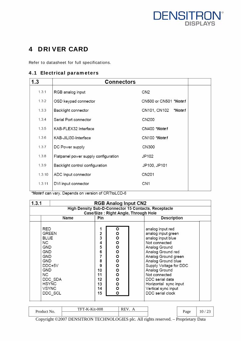
4 DRIVER CARD Refer to datasheet for full specifications.
4.1 Electrical parameters

TFT-K-Kit-008 REV. A Product No. PD064VT4 Page 11 / 23
Copyright ©2007 DENSITRON TECHNOLOGIES plc. All rights reserved. – Proprietary Data

TFT-K-Kit-008 REV. A Product No. PD064VT4 Page 12 / 23
Copyright ©2007 DENSITRON TECHNOLOGIES plc. All rights reserved. – Proprietary Data

TFT-K-Kit-008 REV. A Product No. PD064VT4 Page 13 / 23
Copyright ©2007 DENSITRON TECHNOLOGIES plc. All rights reserved. – Proprietary Data

TFT-K-Kit-008 REV. A Product No. PD064VT4 Page 14 / 23
Copyright ©2007 DENSITRON TECHNOLOGIES plc. All rights reserved. – Proprietary Data

TFT-K-Kit-008 REV. A Product No. PD064VT4 Page 15 / 23
Copyright ©2007 DENSITRON TECHNOLOGIES plc. All rights reserved. – Proprietary Data

TFT-K-Kit-008 REV. A Product No. PD064VT4 Page 16 / 23
Copyright ©2007 DENSITRON TECHNOLOGIES plc. All rights reserved. – Proprietary Data

TFT-K-Kit-008 REV. A Product No. PD064VT4 Page 17 / 23
Copyright ©2007 DENSITRON TECHNOLOGIES plc. All rights reserved. – Proprietary Data

TFT-K-Kit-008 REV. A Product No. PD064VT4 Page 18 / 23
Copyright ©2007 DENSITRON TECHNOLOGIES plc. All rights reserved. – Proprietary Data

TFT-K-Kit-008 REV. A Product No. PD064VT4 Page 19 / 23
Copyright ©2007 DENSITRON TECHNOLOGIES plc. All rights reserved. – Proprietary Data

TFT-K-Kit-008 REV. A Product No. PD064VT4 Page 20 / 23
Copyright ©2007 DENSITRON TECHNOLOGIES plc. All rights reserved. – Proprietary Data

TFT-K-Kit-008 REV. A Product No. PD064VT4 Page 21 / 23
Copyright ©2007 DENSITRON TECHNOLOGIES plc. All rights reserved. – Proprietary Data

TFT-K-Kit-008 REV. A Product No. PD064VT4 Page 22 / 23
Copyright ©2007 DENSITRON TECHNOLOGIES plc. All rights reserved. – Proprietary Data
4.2 Mechanical parameters

TFT-K-Kit-008 REV. A Product No. PD064VT4 Page 23 / 23
Copyright ©2007 DENSITRON TECHNOLOGIES plc. All rights reserved. – Proprietary Data
5 Technical support For technical support, please contact us at [email protected] or visit our website: www.densitron.co.uk.