tf flex joint and tf bundle stub - pppl evms...
TRANSCRIPT

NSTX Upgrade
TF Flex Joint and TF Bundle Stub
NSTXU-CALC-132-06-01
Rev 1
February 2, 2011
Prepared By:
___________________________________ Tom Willard
Reviewed By:
________________________________________ Ali Zolfaghari
Approved By:
_______________________________________ Jim Chrzanowski, NSTX Cognizant Engineer

PPPL Calculation Form
Calculation # NSTX-CALC-132-06 Revision # 01 ___ WP #, if any ________ (ENG-032)
Purpose of Calculation: (Define why the calculation is being performed.) To determine if the upgrade TF flex joint and bundle stub design is adequate to meet the requirements of the NSTX Structural Design Criteria, specifically, the fatigue requirements of Section I-4.2 for 60,000 full power cycles without failure. References (List any source of design information including computer program titles and revision levels.) [1] NSTX Structural Design Criteria Document, I. Zatz [2] NSTX Design point, June 2010 [3] ANSYS v13.0 [4] Maxwell v14.0 Assumptions (Identify all assumptions made as part of this calculation.) 1.) Because it results in the largest background field at the radial center of the flex strap, Current Scenario #81 was assumed worst-case for this analysis. 2.) A one-way coupled electromagnetic-structural analysis was used, based on the assumption that the bolted joints do not separate. This assumption was proven valid by checking the contact status of the joints after the analysis was completed. Calculation (Calculation is either documented here or attached) See attached. Conclusions (Specify whether or not the purpose of the calculation was accomplished.) 1.The maximum stress in the lamellae is 19 ksi, below the NSTX Design Criteria allowable to meet the fatigue requirements for 60,000 full-power cycles; 2.) The HeliCoil and SuperBolt stresses are below the maximum allowable to meet the fatigue requirement ; 3.) The bolted joints were shown not to separate, and the minimum contact pressure is well above the design goal of 1500 psi. 4.) The dynamic load factor was calculated for the flex strap alone. A full transient electromagnetic disruption analysis using the worst-case combination of current and plasma disruption scenarios should be performed to fully qualify the joint and flex strap designs. Cognizant Engineer’s printed name, signature, and date
___________________________________________________________________________
I have reviewed this calculation and, to my professional satisfaction, it is properly performed and correct. Checker’s printed name, signature, and date
___________________________________________________________________________

NSTXU‐CALC‐132‐06‐01TF Flex Joint and TF Bundle Stub
02-03-11
Study Goals
• Purpose:To determine if the upgrade TF flex joint and bundle stub design pg j gis adequate to meet the requirements of the NSTX Structural Design Criteria, specifically, the fatigue requirements of Section I-4.2 for 60,000 full power cycles without failure. – Strap Lamellae
• Stresses• Bucklingg
– Bolted Joints• Thread shear stress• Contact status and pressurep
2NSTXNSTX 2
Outline
• Wire EDM Flex Strap and Joint Design– Flex Strap– Superbolt Jack-screw Tensioned NutSuperbolt Jack screw Tensioned Nut
• Analysis– Magnetostatic
• Magnetic Flux DensityMagnetic Flux Density• Current Density
– Transient Thermal• Temperature
St ti St t l– Static Structural• Conductor Stress• Lamella Stress• Thread and Bolt Stress• Contact Pressure
• Development Tests• Conclusion
3NSTXNSTX 3

4NSTXNSTX 4
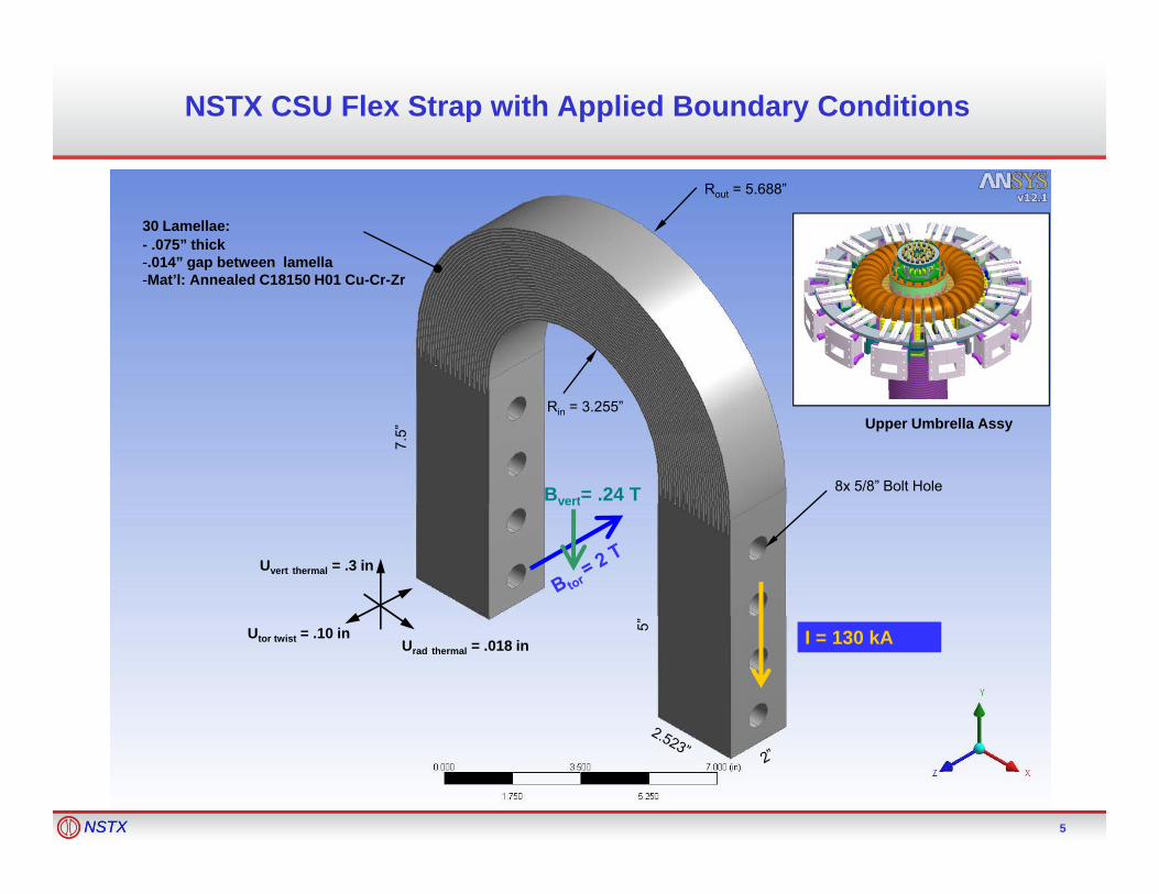
NSTX CSU Flex Strap with Applied Boundary Conditions
30 Lamellae:- .075” thick -.014” gap between lamellaMat’l: Annealed C18150 H01 Cu Cr Zr
Rout = 5.688”
-Mat’l: Annealed C18150 H01 Cu-Cr-Zr
Bvert= .24 T
7.5”
Rin = 3.255”
8x 5/8” Bolt Hole
Upper Umbrella Assy
vert
Uvert thermal = .3 in
I = 130 kAUrad thermal = .018 in5”Utor twist = .10 in
5NSTXNSTX 5

Flex Joint Design using Superbolt Jack-ScrewTensioned Nuts
6NSTXNSTX 6
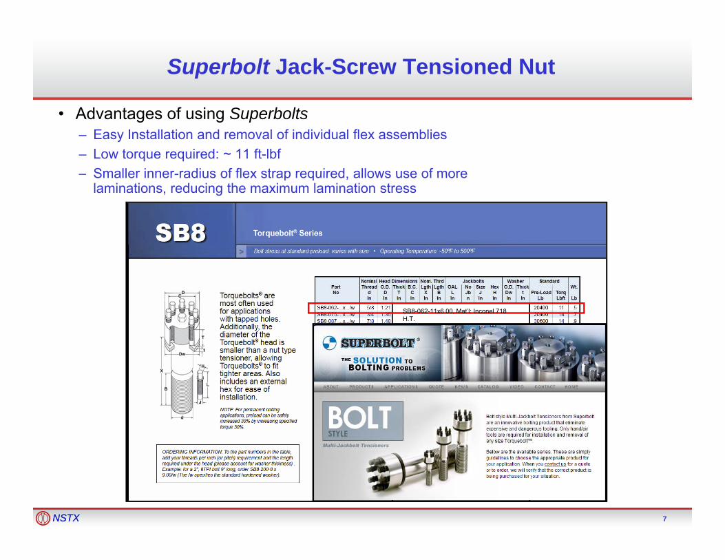
Superbolt Jack-Screw Tensioned Nut
• Advantages of using Superbolts– Easy Installation and removal of individual flex assemblies– Low torque required: ~ 11 ft-lbf– Smaller inner-radius of flex strap required allows use of more– Smaller inner-radius of flex strap required, allows use of more
laminations, reducing the maximum lamination stress
SB8-062-11x6.00, Mat’l: Inconel 718 H.T.
7NSTXNSTX 7

Coupled Maxwell Magnetostatic and ANSYS Transient Thermal/ Static Structural Analysis Block Diagram
Heat Temp
Magnetostatics (Maxell)
Lorentz Forces
g ( )
Note: This sequential, one-way coupled analysis is only valid if the bolted joints do not separate, and if the electrical and thermal contact resistances are a weak function of contact pressure, which is true in
8NSTXNSTX 8
p ,this case if the minimum local contact pressure is above 1500 psi.

SolidWorks Model of 3 Strap Assembly with Simplified OH, PF, and TF Coils
9NSTXNSTX 9

Maxwell Magnetostatic Analysis: DM Solid Model310 Laminations/ Strap
10NSTXNSTX 10

Maxwell Magnetostatic Results: Current DensityCurrent Scenario #82, 30 Laminations/ Strap
11NSTXNSTX 11

Maxwell Magnetostatic Results: Ohmic LossCurrent Scenario #82, 30 Laminations/ Strap
12NSTXNSTX 12
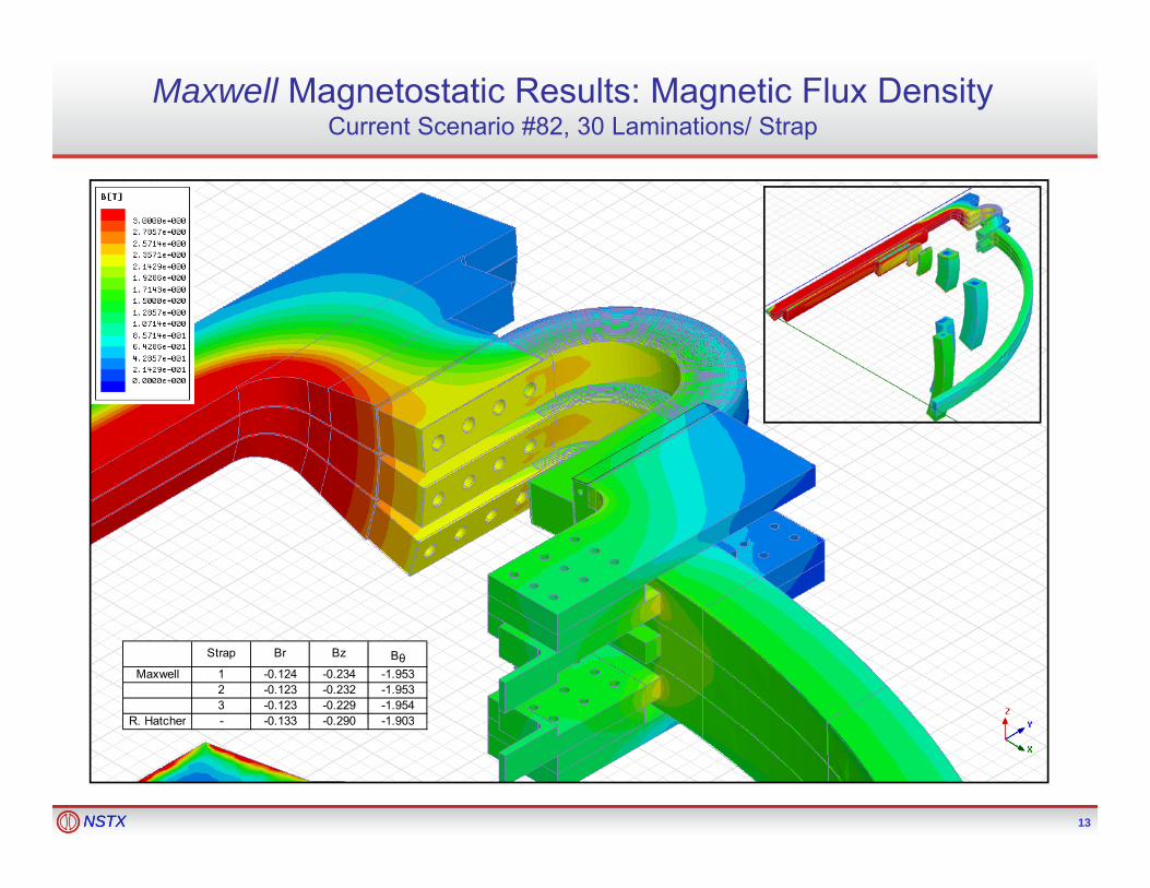
Maxwell Magnetostatic Results: Magnetic Flux DensityCurrent Scenario #82, 30 Laminations/ Strap
Strap Br Bz BθMaxwell 1 -0.124 -0.234 -1.953
2 -0.123 -0.232 -1.9533 -0.123 -0.229 -1.954
R. Hatcher - -0.133 -0.290 -1.903
13NSTXNSTX 13
R. Hatcher 0.133 0.290 1.903

ANSYS Thermal and Structural Analysis Solid Model30 Laminations/ Strap
Superbolt pretension = 25000 lbf
Torqued-bolt pretension ~ 6700 lbf
14NSTXNSTX 14

ANSYS Thermal and Structural Analysis Mesh30 Laminations/ Strap
15NSTXNSTX 15
# Nodes = 2,468,759# Elements = 518,097

Parts Common Between Maxwell and ANSYS Analysis30 Laminations/ Strap
16NSTXNSTX 16

ANSYS Transient Thermal Results: TemperatureCurrent Scenario #82, 30 Laminations
17NSTXNSTX 17
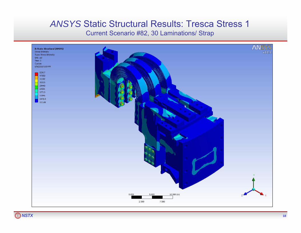
ANSYS Static Structural Results: Tresca Stress 1Current Scenario #82, 30 Laminations/ Strap
18NSTXNSTX 18

ANSYS Static Structural Results: Tresca Stress 2Current Scenario #82, 30 Laminations/ Strap
19NSTXNSTX 19

ANSYS Static Structural Results: Tresca Stress 4Current Scenario #82, 30 Laminations/ Strap
20NSTXNSTX 20

ANSYS Static Structural Results: Lamination Tresca StressCurrent Scenario #82, 30 Laminations/ Strap, Center Strap
21NSTXNSTX 21
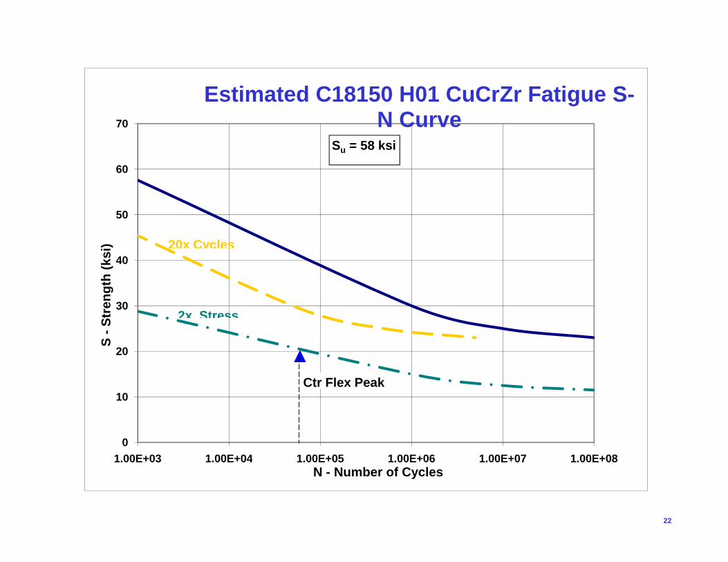
Estimated C18150 H01 CuCrZr Fatigue S-
60
70
gN Curve
Su = 58 ksi
50
) 20x Cycles
30
40
tren
gth
(ksi
) 20x Cycles
2x Stress
20
S -S
t 2x Stress
Ctr Flex Peak
0
10
1 00E+03 1 00E+04 1 00E+05 1 00E+06 1 00E+07 1 00E+08
22
1.00E+03 1.00E+04 1.00E+05 1.00E+06 1.00E+07 1.00E+08N - Number of Cycles

ANSYS Static Structural Results: Joint Tresca StressCurrent Scenario #82, 30 Laminations/ Strap
23NSTXNSTX 23

Modified Goodman Diagram: C18150 TL04 CuCrZr
50
60 Thread Tresca Stress
2/3
Su = 79 ksiSy = 75
40
σ a(p
si)
Sy 75 ksi
30
Am
plitu
de, σ
Se
10
20
Stre
ss A
00 10 20 30 40 50 60 70 80 90
2/3 Sy Su
24
Mean Stress, σm (psi)

Modified Goodman Diagram: Inconel 718 AMS 5663
140
160 ∅5/8" BoltTension Stress
.9 Sy
Su = 180
100
120
σ a(p
si)
y
60
80
Am
plitu
de,
Se
20
40
Stre
ss
00 20 40 60 80 100 120 140 160 180 200
Mean Stress, σm (psi)
.9 Sy Su
25
, m (p )

ANSYS Static Structural Results: 5/8” Bolted Contact PressureCurrent Scenario #82, 30 Laminations/ Strap
26NSTXNSTX 26
Min. Pressure ~ 4500 psi

ANSYS Static Structural Results: 3/8” Bolted Contact PressureCurrent Scenario #82, 30 Laminations/ Strap
27NSTXNSTX 27
Min. Pressure ~ 2500 psi
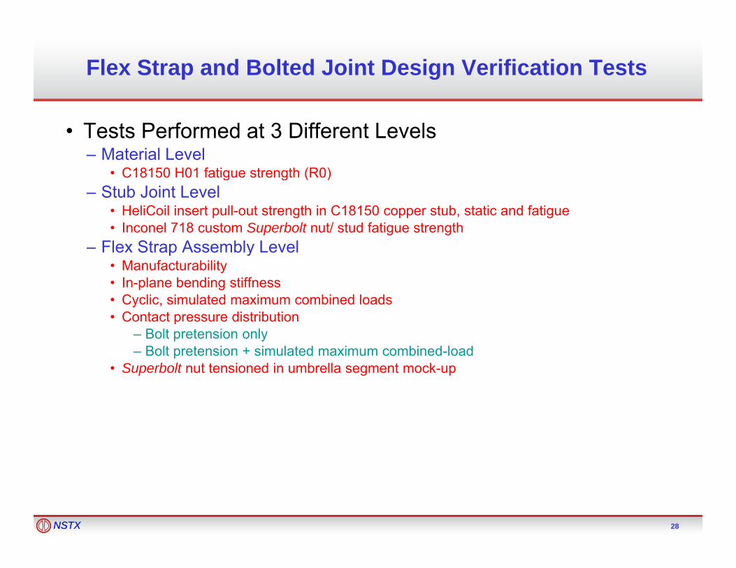
Flex Strap and Bolted Joint Design Verification Tests
• Tests Performed at 3 Different Levels– Material Level
• C18150 H01 fatigue strength (R0)C18150 H01 fatigue strength (R0)– Stub Joint Level
• HeliCoil insert pull-out strength in C18150 copper stub, static and fatigue• Inconel 718 custom Superbolt nut/ stud fatigue strength
– Flex Strap Assembly Level– Flex Strap Assembly Level• Manufacturability• In-plane bending stiffness• Cyclic, simulated maximum combined loads• Contact pressure distributionContact pressure distribution
– Bolt pretension only– Bolt pretension + simulated maximum combined-load
• Superbolt nut tensioned in umbrella segment mock-up
28NSTXNSTX 28
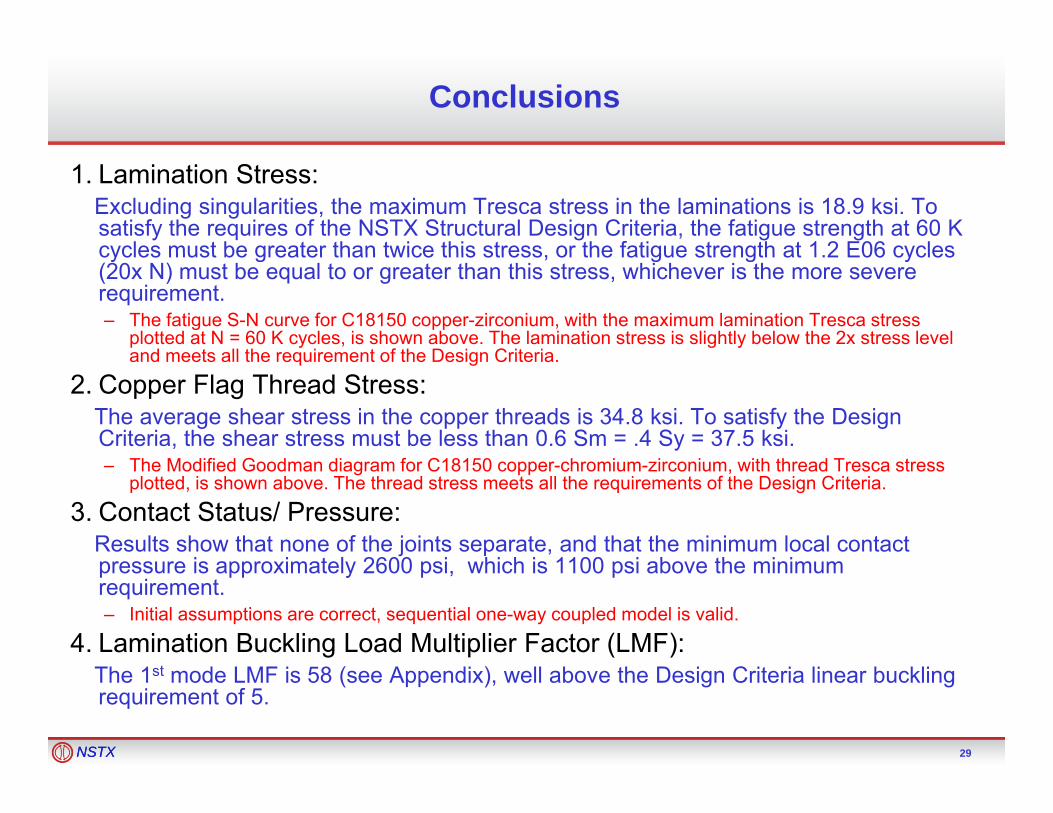
Conclusions
1. Lamination Stress: Excluding singularities, the maximum Tresca stress in the laminations is 18.9 ksi. To satisfy the requires of the NSTX Structural Design Criteria, the fatigue strength at 60 K cycles must be greater than twice this stress or the fatigue strength at 1 2 E06 cyclescycles must be greater than twice this stress, or the fatigue strength at 1.2 E06 cycles (20x N) must be equal to or greater than this stress, whichever is the more severe requirement. – The fatigue S-N curve for C18150 copper-zirconium, with the maximum lamination Tresca stress
plotted at N = 60 K cycles, is shown above. The lamination stress is slightly below the 2x stress level and meets all the requirement of the Design Criteriaand meets all the requirement of the Design Criteria.
2. Copper Flag Thread Stress:The average shear stress in the copper threads is 34.8 ksi. To satisfy the Design Criteria, the shear stress must be less than 0.6 Sm = .4 Sy = 37.5 ksi.
f G f C181 0– The Modified Goodman diagram for C18150 copper-chromium-zirconium, with thread Tresca stress plotted, is shown above. The thread stress meets all the requirements of the Design Criteria.
3. Contact Status/ Pressure:Results show that none of the joints separate, and that the minimum local contact
i i t l 2600 i hi h i 1100 i b th i ipressure is approximately 2600 psi, which is 1100 psi above the minimum requirement.– Initial assumptions are correct, sequential one-way coupled model is valid.
4. Lamination Buckling Load Multiplier Factor (LMF):
29NSTXNSTX 29
The 1st mode LMF is 58 (see Appendix), well above the Design Criteria linear buckling requirement of 5.
Appendix A
Lamella Stress Linearization
30NSTXNSTX 30

ANSYS Static Structural Results: Lamination Tresca Stress Current Scenario #82, 30 Laminations/ Strap
31NSTXNSTX 31
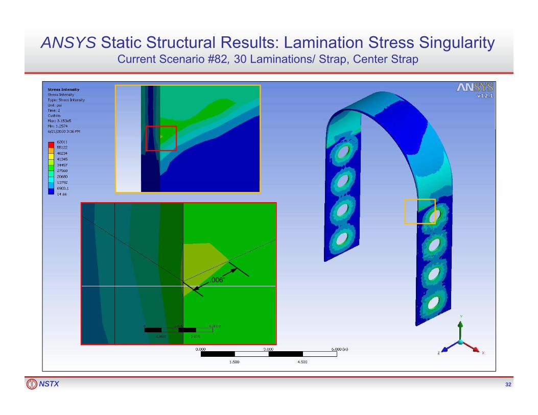
ANSYS Static Structural Results: Lamination Stress SingularityCurrent Scenario #82, 30 Laminations/ Strap, Center Strap
.006”
32NSTXNSTX 32
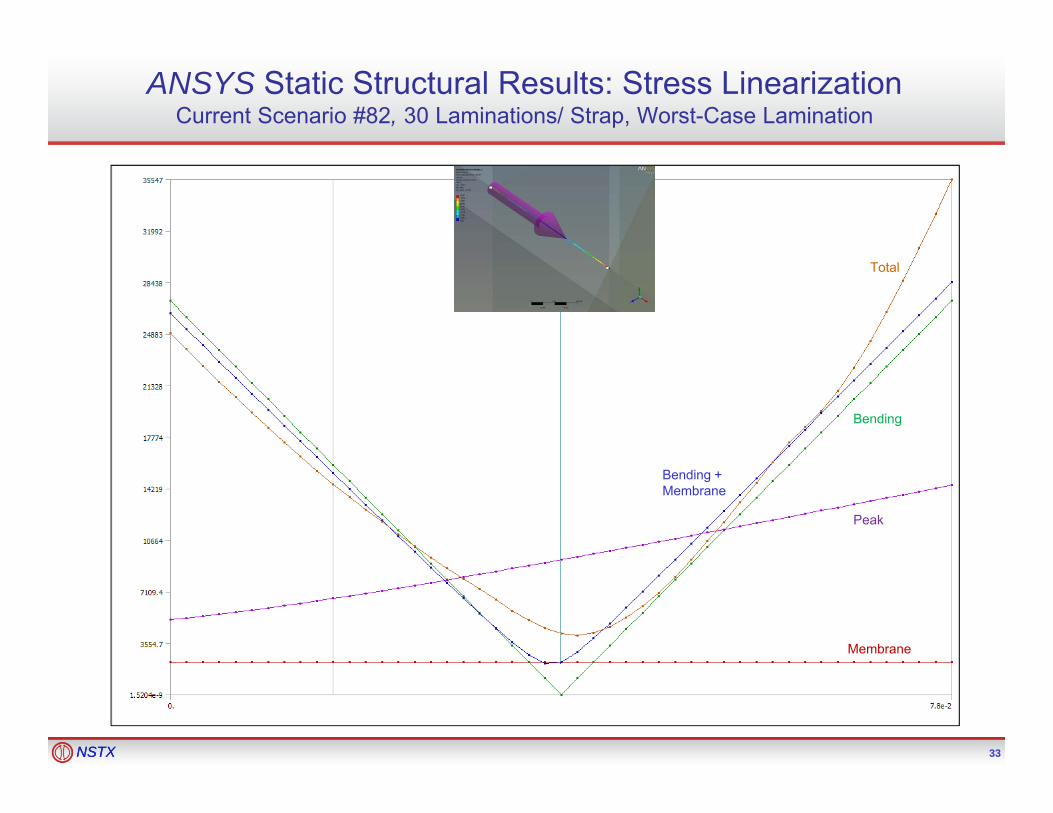
ANSYS Static Structural Results: Stress LinearizationCurrent Scenario #82, 30 Laminations/ Strap, Worst-Case Lamination
Total
Bending
Peak
Bending + Membrane
Membrane
33NSTXNSTX 33
Appendix B
Lamella Buckling Analysis
34NSTXNSTX 34
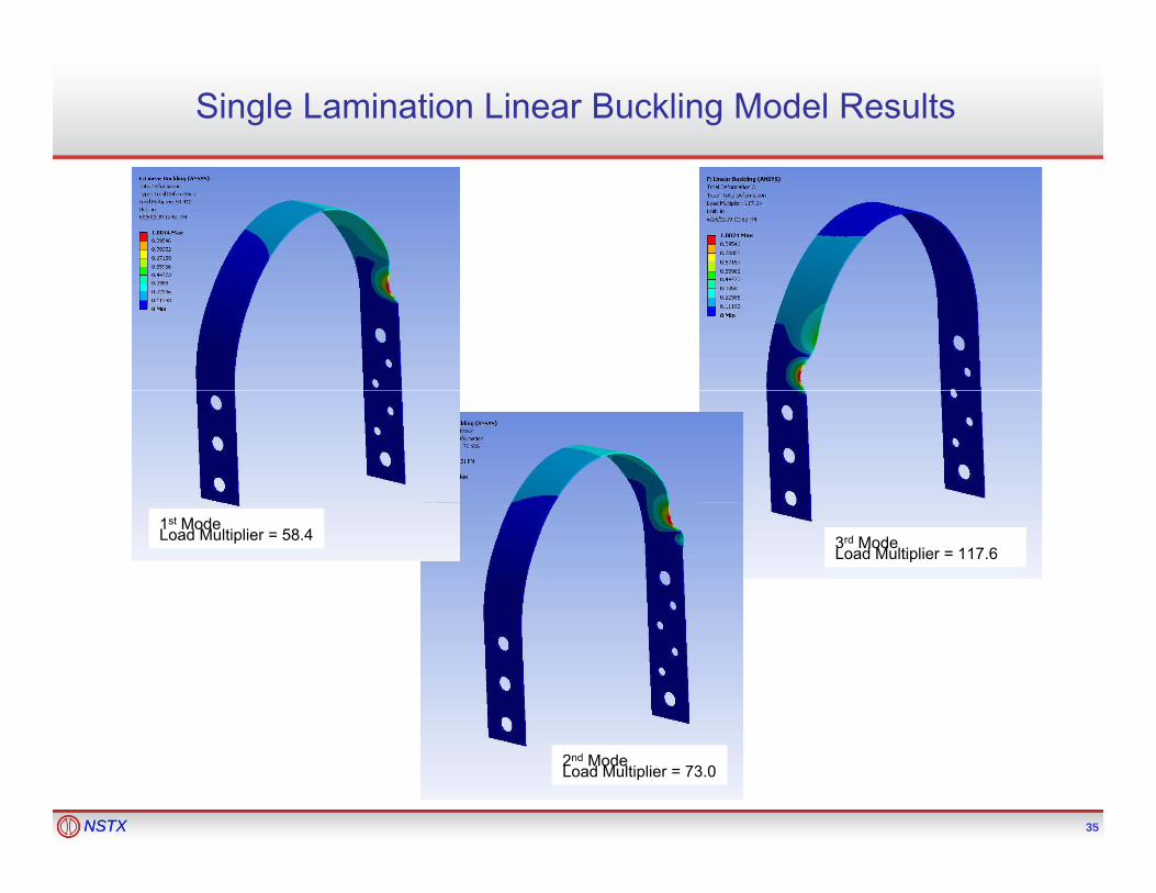
Single Lamination Linear Buckling Model Results
3rd ModeLoad Multiplier = 117.6
1st ModeLoad Multiplier = 58.4
35NSTXNSTX 35
2nd ModeLoad Multiplier = 73.0

Appendix C
Flex Strap Dynamic Load Factor
36NSTXNSTX 36
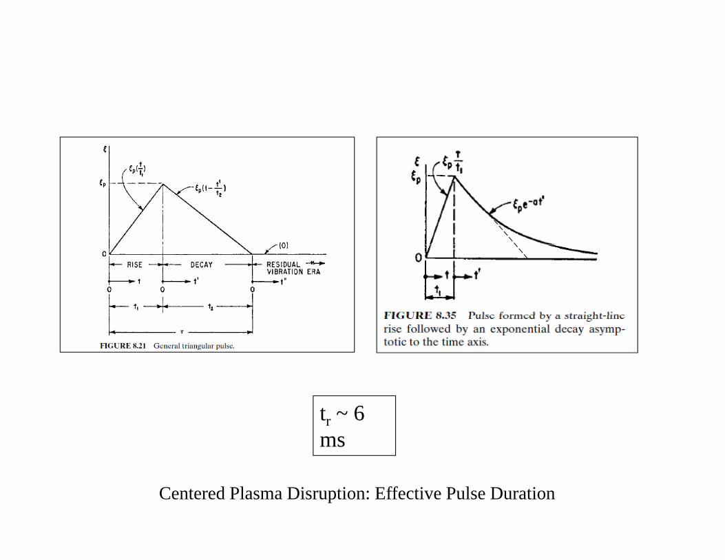
tr ~ 6 ms
Centered Plasma Disruption: Effective Pulse Duration

Modal Analysis Results: Flex Strap Mode 1 = 65 Hz
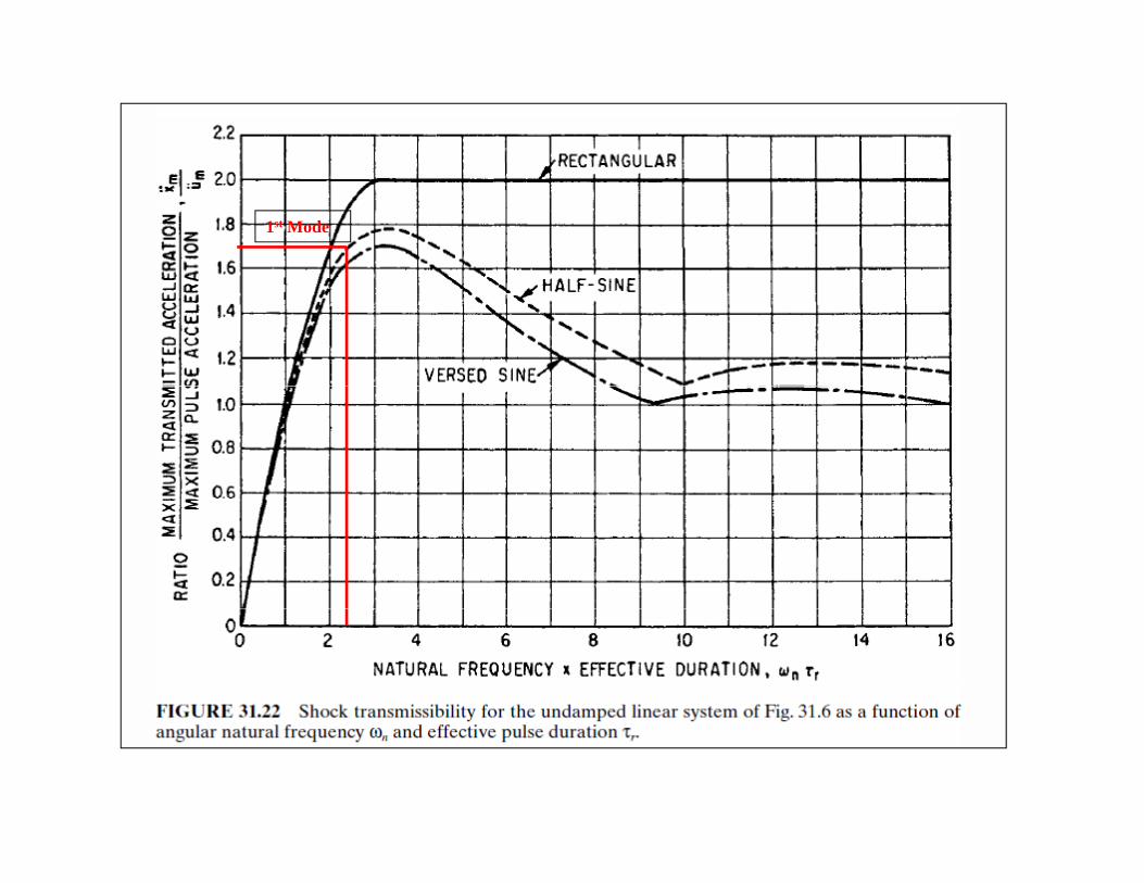
1st Mode