textile composites and inflatable...
TRANSCRIPT

TEXTILE COMPOSITES AND INFLATABLE STRUCTURES

Computational Methods in Applied Sciences
Volume 3
Series Editor
E. Oñate
Textile Composites andInflatable Structures
Edited by
EUGENIO OÑATECentro Internacional de Métodos Numéricos en Ingeniería (CIMNE),
Universidad Politécnica de Cataluña, Barcelona, Spain
and
Institut für Statik und Dynamik der Luft- und Raumfahrtkonstruktionen,
Stuttgart, Germany
BERN KRÖPLIN
A C.I.P. Catalogue record for this book is available from the Library of Congress.
Published by Springer,P.O. Box 17, 3300 AA Dordrecht, The Netherlands.
Printed on acid-free paper
All Rights Reserved© 2005 Springer
No part of this work may be reproduced, stored in a retrieval system, or transmittedin any form or by any means, electronic, mechanical, photocopying, microfilming, recordingor otherwise, without written permission from the Publisher, with the exceptionof any material supplied specifically for the purpose of being enteredand executed on a computer system, for exclusive use by the purchaser of the work.
Printed in the Netherlands.
ISBN-10 1-4020-3316-8 (HB) Springer Dordrecht, Berlin, Heidelberg, New YorkISBN-10 1-4020-3317-6 (e-book) Springer Dordrecht, Berlin, Heidelberg, New YorkISBN-13 978-1-4020-3316-2 (HB) Springer Dordrecht, Berlin, Heidelberg, New YorkISBN-13 978-1-4020-3317-9 (e-book) Springer Dordrecht, Berlin, Heidelberg, New York
Table of Contents
On the Design Process of Tensile StructuresR. Wagner . . . . . . . . . . . . . . . . . . . . . . . . . . . . . . . . . . . . . . . . . . . . . . . . . . . . . . . . . . . .1
Systems for Lightweight Structure Design: the State-of-the-Art and CurrentDevelopmentsE. Moncrieff . . . . . . . . . . . . . . . . . . . . . . . . . . . . . . . . . . . . . . . . . . . . . . . . . . . . . . . . . 17
Recent Developments in the Analytical Design of Textile MembranesL. Grundig, D. Str¨¨ obel and P. Singer . . . . . . . . . . . . . . . . . . . . . . . . . . . . . . . . 29¨
Finite Element Analysis of Membrane StructuresR.L. Taylor, E. Onate and P.A. Ubach . . . . . . . . . . . . . . . . . . . . . . . . . . . . . . . 47˜
Applications of a Rotation-Free Triangular Element for Finite Strain Analysisof Thin Shells and MembranesF. Flores and E. Onate . . . . . . . . . . . . . . . . . . . . . . . . . . . . . . . . . . . . . . . . . . . . . . 69˜
FE Analysis of Membrane Systems Including Wrinkling and CouplingR. Rossi, V. Renato and E. Onate . . . . . . . . . . . . . . . . . . . . . . . . . . . . . . . . . . . 89˜
Wrinkles in Square MembranesY.W. Wong and S. Pellegrino . . . . . . . . . . . . . . . . . . . . . . . . . . . . . . . . . . . . . . . 109
FEM for Prestressed Saint Venant-Kirchhoff Hyperelastic MembranesA. J. Gil . . . . . . . . . . . . . . . . . . . . . . . . . . . . . . . . . . . . . . . . . . . . . . . . . . . . . . . . . . . 123
Equilibrium Consistent Anisotropic Stress Fields in Membrane DesignK.-U. Bletzinger, R. Wuchner and F. Daoud .¨ . . . . . . . . . . . . . . . . . . . . . . . 143
Efficient Finite Element Modelling and Simulation of Gas and Fluid SupportedMembrane and Shell StructuresT. Rumpel, K. Schweizerhof and M. Haßler . . . . . . . . . . . . . . . . . . . . . . . . 153
Widespan Membrane Roof Structures: Design Assisted by ExperimentalAnalysisM. Majowiecki . . . . . . . . . . . . . . . . . . . . . . . . . . . . . . . . . . . . . . . . . . . . . . . . . . . . .173
Fabric Membranes Cutting PatternB. Maurin and R. Motro . . . . . . . . . . . . . . . . . . . . . . . . . . . . . . . . . . . . . . . . . . . 195
v
Preface . . . . . . . . . . . . . . . . . . . . . . . . . . . . . . . . . . . . . . . . . . . . . . . . . . . . . . . . . . . . . . . . . . . vii

Inflated Membrane Structures on the Ground in the Air and in Space -A ClassificationB. Kroplin . . . . . . . . . . . . . . . . . . . . . . . . . . . . . . . . . . . . . . . . . . . . . . . . . . . . . . . . . 213¨
Post-Tensioned Modular Inflated StructuresR. Tarczewski . . . . . . . . . . . . . . . . . . . . . . . . . . . . . . . . . . . . . . . . . . . . . . . . . . . . . . 221
Experiences in the Design Analysis and Construction of Low PressureInflatable StructuresJ. Marcipar, E. Onate and J. Miquel Canet . . . . . . . . . . . . . . . . . . . . . . . . . 241˜
Recent Advances in the Rigidization of Gossamer StructuresB. Defoort, V. Peypoudat, M.C. Bernasconi, K. Chuda andX. Coqueret . . . . . . . . . . . . . . . . . . . . . . . . . . . . . . . . . . . . . . . . . . . . . . . . . . . . . . . . 259
Form-Optimizing Processes in Biological Structures. Self-generatingstructures in nature based on pneumaticsE. Stach. . . . . . . . . . . . . . . . . . . . . . . . . . . . . . . . . . . . . . . . . . . . . . . . . . . . . . . . . . . .285
Making Blobs with a Textile Mould
vi
A.C.D. Pronk and R. Houtman. . . . . . . . . . . . . . . . . . . . . . . . . . . . . . . . . . . . . .305
Table of Contents

PREFACE
The objective of this book is to collect state-of-the-art research and tech-nology for design, analysis, construction and maintenance of textile andinflatable structures.
Textile composites and inflatable structures have become increasinglypopular for a variety of applications in - among many other fields - civilengineering, architecture and aerospace engineering. Typical examples in-clude membrane roofs and covers, sails, inflatable buildings and pavilions,airships, inflatable furniture, airspace structures etc.
The ability to provide numerical simulations for increasingly complexmembrane and inflatable structures is advancing rapidly due to both re-markable strides in computer hardware development and the improvedmaturity of computational procedures for nonlinear structural systems.Significant progress has been made in the formulation of finite elementsmethods for static and dynamic problems, complex constitutive materialbehaviour, coupled aero-elastic analysis etc.
The book contains 18 invited contributions written by distinguishedauthors who participated in the International Conference on Textile Com-puter and Inflated Structures held in Barcelona from June 30th to July 2nd2003. The meeting was one of the Thematic Conferences of the EuropeanCommunity on Computational Methods in Applied Sciences (ECCOMAS,www.eccomas.org).
The different chapters discuss recent progress and future research direc-tions in new textile composites for applications in membrane and inflatablestructures. Approximately half of the book focuses in describing innovativenumerical methods for structural analysis, such as new non linear mem-brane and shell finite elements. The rest of the chapters present advancesin design, construction and maintenance procedures.
The content of the different chapters was sent directly by the authorsand the editors cannot accept responsibility for any inaccuracies, commentsand opinions contained in the text.
The editors would also like to take this opportunity to thank all authorsfor submitting their contributions.
Eugenio Onate Bernard Kr˜ oplin¨Universitat Politecnica de Catalunya University of Stuttgart`Barcelona, Spain Stuttgart, Germany
vii
On the Design Process of Tensile Structures
Rosemarie Wagner1
Fachhochschule Munchen¨Fachbereich ArchitekturKarlstrasse 6, D-80333 Munchen, Germany¨[email protected]
Web page: http://www.lrz-muenchen.de/∼architektur
Summary. The influence of the development of computer programmes and auto-matic generation of cable nets and membrane structures will be shown in some ex-amples. The main interest is laying on new evaluation methods of cable nets andmembrane structure and the design process of membrane structures, integrating thematerial behaviour of coated fabric.
Key words: Design process, cable nets, membrane structures, inflated structures
1 Introduction
The design process of pretensioned structures such as cable nets and membranestructures is influenced by the development of computational methods. While thefirst methods of form finding had been physical modelling with fabric, wire nets orsoap films, today several numerical methods of form finding are developed based onthe force density method [1,2], the principle of minimal surfaces [3,4] using dynamicrelaxation [5,6] or other approaches in fulfilling the three-dimensional equilibrium.Further process has been carried out in the form finding with an anisotropic stressdistribution [7]. All methods have in common that no material laws are necessaryfinding an equilibrium of the three dimensional shape for given stress distributions,boundary conditions and supports. These shapes of equilibrium should ensure inthe built structure a homogeneous distribution of the tension stresses. In reality thematerial behaviour, process of cutting patterns, manufacturing and pretensioningon site influencing the stress distribution, wrinkles and regions of over stress areobvious, can be seen and measured.
The design process of pretensioned structures needed to be extended takinginto account evaluation methods for shapes of equilibrium in relation the mate-rial behaviour and process of prestensioning. More realistic modelling of membranestructures is necessary including the strips in width, orientation of the fabric andseams for analysing the load charring behaviour. The process of reassembling flat-ten strips had already been proposed for a rotational symmetric hat type tent [8].The process of form finding can be embedded in a design process including cuttingpattern und structural behaviour under external loads. The load bearing behaviour
1
E. Oñate and B. Kröplin (eds.), Textile Composites and Inflatable Structures, 1–16. © 2005 Springer. Printed in the Netherlands.

2 Rosemarie Wagner
can be evaluated by redundancy, flexibility or a stiffness value in relation to thecurvature and the elastic strain of the materials.
2 State of the Art
The design process of tension structures such as double curved cable nets or mem-brane structures such as tents, air support halls or airships can be divided into formfinding, static analysis and cutting pattern. The result of the form finding is a shapeof equilibrium for a certain stress distribution and boundary conditions. The shapeof equilibrium ensures the geometry of the double curved surface which has onlytension and avoids compression in the surface. From this geometry the structuralbehaviour is exanimated and the cutting pattern is made of. The flattening of thedouble curved surface is a geometrical process without considering the stress dis-tribution and the material behaviour. In the recent development of cutting patternmethods the stress distribution is taking into account [9,10]. The analysis of thestructural behaviour is carried out without the influence of the width of the strips,the seams, the orientation of the fabric and the process of pretensioning. The separa-tion of the structural behaviour and the cutting pattern leads in built structures tohighly inhomogeneous stress distributions which can be seen in wrinkles and mea-sured in stresses which are two times higher than required. The difference in thestress distribution and geometry between the numerical found shape of equilibriumand the real structure causes in the non consistent design procedure see Fig. 1.
Fig. 1. Common design process of membrane structures
3 Enhanced Design Process of Tension Structures
An enhanced design concept will be based on 5 design steps defining the shape ofequilibrium, generating the cutting pattern, reassembling and pretensioning the cut-ting pattern, the structural analysis of the reassembled structure and the evaluationof the structural behaviour. The material behaviour is considered in the last threesteps: flattening the shape of equilibrium, reassembling and load bearing behaviour.The length and the width of the strips has an influence to the shear deformation ofthe coated fabric. The orthotropic behaviour of coated fabric influences the processof pretension and the stress distribution in the reassembled structure. The numericalprocess allows after evaluation modifications to reach better results in the reassemblestructures considering stress distribution and deformations.
Shape of equilibrium
given stress distribution
no material behaviour
Structural Behaviour
no influence of warp and weft orientation
no influence of the seams
no influence of width of the strips
no influence of the shear deformation of the fabric
no consideration of the process of pretensioning
Cutting Pattern
No material behaviour
No stress distribution

On the Design Process of Tensile Structures 3
Fig. 2. Enhanced design process of membrane structures [11]
3.1 Shape of Equilibrium
The development of Computer Aided Geometric Design (CAGD) marked the startof changes in geometry endorsing new and free forms. This generation of doublecurved 3-dimensional surfaces is restricted by few limitations. Theoretically thereare an unlimited number of forms to be numerical generated and represented. How-ever, the manufacture and realization of such double curved surfaces are subject tonumerous boundary conditions and restrictions. Using cables and membranes forthe load transfer only tension forces can be carried, the cables and membranes cannot withstand bending moments and compression forces in a global point of view.The structures have to be pretensioned activating the geometric stiffness or to beable carrying compression forces by reducing the pretension. The shape of equilib-rium defines a pretensioned geometry of a doubled curved surface for a cable netor a membrane structure. The relation between the tension stress, geometry andequilibrium allows three possibilities to introduce the tension into the membranes
Pretension against rigio n aries
traig t ire tionsS1 is in e en ent o S2
Pretension as res t o e iation or es u1 −u2
osite r e ire tionsS1R1
− S2R2
= 0
Pretension as result internal(soil-, fluid- or gas-) pressure p
Same direction of the curvatureS1R1
+ S2R2
= p
Fig. 3. Relation between tension forces and curvature
The pretension against rigid boundaries enables plain tension structures, ten-sion structures with single curvatures and double curved tension structures if thedirection of the cables or yarns is along the evolution line of a hyper parabola. Thetension forces are independent from each other in this case.
Shape of
equilibrium
Generation of
cutting pattern
Reassembling
and preten-
sion
Structural be-
haviour
Evaluation
and influences the shape of equilibrium, see Fig. 3.
S1
S1S
S1
S1
S2S
SS2222SS
S2S
S2
S1
S1S
S1S
S1SS2S
S2S
S2S
SS2S
u1 = – u2
u2
R2
RR1
S1S
S1
S1
S1S
S2S
S2S
S2S
S2Sp1
R2
R1
p2

4 Rosemarie Wagner
The tension forces in surfaces with negative Gaussian curvature result of thedeviation forces at the nodes and this leads to a relation between tension forcesand curvature. Fulfilling the equilibrium at each node the tension forces are relatedto the radius of curvature in the both directions. Equal forces in both directionsrequire the same curvature of the cables. The ratio of tension forces and radius ofcurvature is constant by meaning the higher the forces the lower the curvature toensure equilibrium.
Stabilising the membranes with internal pressure leads to surfaces with positiveGaussian curvature and a dependency between the internal pressure, the tensionforces and the curvature. The tension forces are directly related to the internalpressure and the lower the curvature the higher the forces.
Cable nets with square meshes are cinematic systems, the thin membrane with-out bending stiffness is statically determined. In both cases the double curved surfaceis a result of the three dimensional equilibrium at each node for given tension forcesin a cable net or at each point for a given stress distribution in a membrane. Theequilibrium is fulfilled without taking into account the material behaviour and isinfluenced by the boundary conditions such as high points, boundary cables or rigidboundaries.
For cable nets the numerical solution is based on the constant ratio of cableforce and length in the first step. The ratio of cable force and length is described asforce density [12] and the shape of equilibrium is calculated from a plane net witha square gird by moving the nodes in the third direction, forced by the fixed pointsand boundaries which don’t lie in the same plane as the cable net. Depending on thechange in length from the cable links in the plane into the three dimensional surfacethe cable forces changes, the longer the cables the higher the forces. The result is adoubled curved surface with a steady change in the forces along each cable relatedto the change of curvature of the surface. This method can also be exceed to cablenets which are statically indeterminate such as nets with triangle meshes becauseof the constant ratio of force/length. Both forces and length of the links are freeparameter searching for the three dimensional equilibrium.
S
l=
Hx
lx=
V
lz= const. Plane net with square meshes
and constant forces in each linkShape of equilibrium
change in forces
Fig. 4. Shape of equilibrium fulfilling vertical equilibrium
Fulfilling the equilibrium in the tangential plane at each knot allows adjustingthe link length and leads to constant forces in each cable. The cables are orientedalong geodesic lines onto the surface and the angles are not constant at the nodesbetween crossing cables.
In membranes the equilibrium has to be fulfilled at each point of the surface.Plane state of stress assumed shapes of equilibrium are also the result of a given stress
S1S
l1
lx 1l
Hx,1HH

On the Design Process of Tensile Structures 5
Fig. 5. Shape of equilibrium fulfilling vertical and tangential equilibrium
distribution. In general and in covariant description [13] the equilibrium normal tothe surface is written as:
σαβbαβ = 0 , with bαβ as tensor of curvature
Related to main axis
σ11b11 + σ12b12 + σ21b21 + σ22b22 = 0
The orientation of the coordinate system in direction of the principle stresses(σ12 = σ21 = 0) or principle curvature (b12 = b21 = 0)
σ11b11 + σ22b22 = 0
Tension stresses in both principle directions σ11 ≥ 0 und σ22 ≥ 0 requires anegative Gaussian curvature, with b11 = 1
R1and b22 = − 1
R2the equilibrium normal
to the surface results inσ11
R1− σ22
R2= 0
The equilibrium in the tangential plane of the point can be written in covariantdescription as
σαβ|β = 0
Assuming the stress is constant at a certain point leads to
σαβ = σgαβ with gαβ as metric tensor
Substituted(σgαβ)|β = 0 ⇒ σ|βgαβ + σgαβ
|β︸ ︷︷︷ ︸︸⇒0
= 0
and results inσ|βgαβ = 0
The metric tensor has a certain value at each point in a double curved surface;this means the deviation of the stress has to be zero. This requires a constant stressdistribution also to neighboured points and describes the hydrostatic state of stress.Therefore has to be σ11 = σ22 = constant and with
σ11
R1− σ22
R2= 0 ⇒
(R2 − R1
R1 · R2
)= 0 and R1 = R2
Plane net with square meshes
and constant forces in each link
Shape of equilibrium
constant forces at each link

6 Rosemarie Wagner
The tension stress in the surface is isotropic and homogeneous by meaning thestresses are at each point and in each direction constant and this is named as hy-drostatic state of stress. The stress can be set as a constant value and reduces thedescription of shapes of equilibrium to the geometrical problem searching for theminimal surface by given boundary conditions. Physical models of minimal surfacesare soap films, in earlier times one of the few methods describing double curvedsurfaces which are at each point under tension.
Soap film [14] Numerical solution of the minimal surface [15]
Fig. 6. Minimal surfaces as soap film and the numerical solution
3.2 Cutting Pattern
The shapes of equilibrium are characterized by no material behaviour or by thematerial behaviour of soap films without shear resistance. The real shape of the ten-sioned structures is influenced by the material behaviour and the difference betweenthe shape of equilibrium and the materialized, pretensioned shape resulting in thenon existing shear stiffness of a cable net, the orthotropic behaviour of coated fabricor the relatively high shear stiffness of foils. Known from the globe is the fact thatdouble curved surfaces cannot be flattened without distortion. Furthermore the fab-ric is manufactured in width up to max. 5 m and this requires the assembling of thewhole cover with patches or strips of a certain length and width. The common wayof generating the cutting pattern from the shape of equilibrium is described in foursteps. The shape of equilibrium is cut into strips mostly using geodesic lines for thecutting lines. The whole structure is then divided into double curved strips. Thesestrips are flattened with different methods such a paper strip method or minimiz-ing the strain energy while flattening the strips. The compensation as final step isnecessary to introduce the tension forces by elongation of the fabric. All strips haveto be decreased in width and length in relation to the stress and strain behaviourof the fabric in the built structure.
Differences in geometry and stresses between the shape of equilibrium and thebuilt structure are caused by the orientation of the fabric, the shear deformation ofthe fabric, the stiffness of the seams und the process of pretension. Reducing themistakes in the cutting pattern which can be seen in wrinkles and can be measuredin local stress peaks is possible by taking into account the jamming condition ofthe coated fabric. The load carrying compounds in a fabric are the yarns which areprotected by the coating. In a woven fabric warp and fill will kept in place if thetension stress acts in direction of the yarns. Shear forces lead to a rotation of warpand fill against each other up to an angle when the yarns touch each other. The

On the Design Process of Tensile Structures 7
Fig. 7. Generation of cutting pattern [16]
Fig. 8. Shear deformation of woven fabric [17]
maximum shear deformation is depended by the thickness of the yarns, the distanceof the yarns and the flexibility of the coating. If the rotation of the yarns is largerthan the required distortion to flatten the doubled curved strips the flattening isonly a process of strainless deformation.
If the process is invert and still definite needs further examination because themanufacturing of membrane structures is from the flat and assembled strips into thedouble curved and pretensioned structure. Already known is the shear deformationwhich is used to build double curved surfaces with cable nets. The cable net can beput onto the doubled curved surface just by changing the angles between the cables;the distance between the nodes is kept as constant. The rotation of the two layersof cables against each other is related to the curvatures of the surface.
Fig. 9. Shear deformation from the plane into the double curved net
Dividing the surface by
geodesic lines
Separating the strips
along the geodesic lines
Flattening of the strips compensation
Plane net with square meshes Plane and double curved net Double curved net

8 Rosemarie Wagner
Fig. 10. Model describing the behaviour of a woven fabric
3.3 Reassembling and Pretensioning
The tension forces can only be introduced into cable nets or membranes by elasticstrain of the cables and coated fabric. The numerical process of reassembly requiresthe description of the material behaviour in which both the change of the geometryand the elastic strain is considered. The change in geometry is for cable nets mostlythe in plane shear deformation reaching the double curved surface. The change ofgeometry in woven fabric is related to the elongation of the yarns. The simple modelis useful enough describing the behaviour of a woven fabric, developed in 1978 [18],refined and tested in 1987 [19] and finally numerical transferred in 2003 [20].
Neglecting the influence of the coating the behaviour of a woven fabric can bedescribed by the
- Geometry of the fabric such as thickness and distance of the yarns (warp A1, L1
and inclination m1 = A1/L1, fill A2, L2 and inclination m2 = A2/L2)- Stress-strain-behaviour of each yarn (warp F1FF , ε1, fill F2FF , ε2 )- The change in the thickness of the fabric (γ) and- The equilibrium of the deviation forces at each knot
The ratio of unstrained to strained length is described by:
µ1 = 1 + U11U and µ2 = 1 + U22UU
With the ratio of undeformed and deformed inclination of
k1 = A1/µ1 and k2 = A2/µ2
is the elastic strain of the yarns
ε1 − µ1
√1 + k2
1m21√
1 + m21
+ 1 = 0 and ε2 − µ2
√1 + k2
2m22√
1 + m22
+ 1 = 0
The constrain of the distance between the yarns at the knots is
k1µ1A1 + k2µ2A2 − A1 − A2 − γF1FFk1m1√
1 + k21m2
1
= 0
Equilibrium of the yarn
F2FFk2m2√
1 + k22m2
2
− F1FFk1m1√
1 + k21m2
1
= 0
Unknown are
Strain of the fabric 11 22U U11 2 [%]
Stress of the fabric 11 22
UUU
UUU
L
L
A
AAA
F
FFF
On the Design Process of Tensile Structures 9
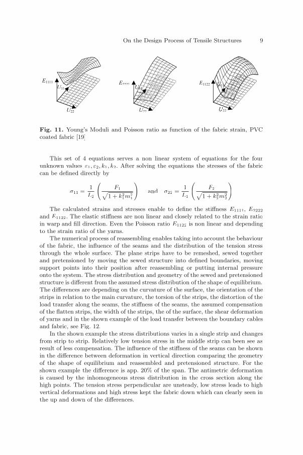
Fig. 11. Young’s Moduli and Poisson ratio as function of the fabric strain, PVCcoated fabric [19]
This set of 4 equations serves a non linear system of equations for the fourunknown values ε1, ε2, k1, k2. After solving the equations the stresses of the fabriccan be defined directly by
σ11 =1
L2
(F1FF√
1 + k21m2
1
)and σ22 =
1
L1
(F2FF√
1 + k22m2
2
)
The calculated strains and stresses enable to define the stiffness E1111, E2222
and E1122. The elastic stiffness are non linear and closely related to the strain ratioin warp and fill direction. Even the Poisson ratio E1122 is non linear and dependingto the strain ratio of the yarns.
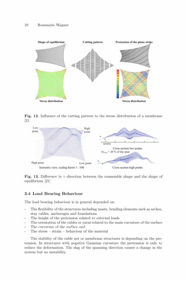
The numerical process of reassembling enables taking into account the behaviourof the fabric, the influence of the seams and the distribution of the tension stressthrough the whole surface. The plane strips have to be remeshed, sewed togetherand pretensioned by moving the sewed structure into defined boundaries, movingsupport points into their position after reassembling or putting internal pressureonto the system. The stress distribution and geometry of the sewed and pretensionedstructure is different from the assumed stress distribution of the shape of equilibrium.The differences are depending on the curvature of the surface, the orientation of thestrips in relation to the main curvature, the torsion of the strips, the distortion of theload transfer along the seams, the stiffness of the seams, the assumed compensationof the flatten strips, the width of the strips, the of the surface, the shear deformationof yarns and in the shown example of the load transfer between the boundary cablesand fabric, see Fig. 12.
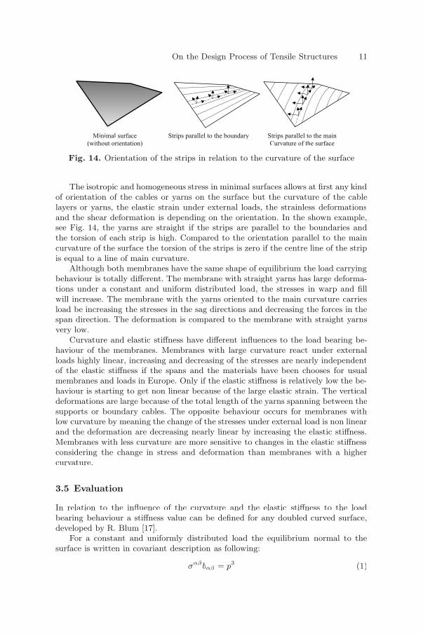
In the shown example the stress distributions varies in a single strip and changesfrom strip to strip. Relatively low tension stress in the middle strip can been see asresult of less compensation. The influence of the stiffness of the seams can be shownin the difference between deformation in vertical direction comparing the geometryof the shape of equilibrium and reassembled and pretensioned structure. For theshown example the difference is app. 20% of the span. The antimetric deformationis caused by the inhomogeneous stress distribution in the cross section along thehigh points. The tension stress perpendicular are unsteady, low stress leads to highvertical deformations and high stress kept the fabric down which can clearly seen inthe up and down of the differences.
U22UU
E2222E
22UU
UUUUUUUE1122
U22UU
U11UUE1111
10 Rosemarie Wagner
Fig. 12. Influence of the cutting pattern to the stress distribution of a membrane[21]
Fig. 13. Difference in z–direction between the reassemble shape and the shape ofequilibrium [21]
3.4 Load Bearing Behaviour
The load bearing behaviour is in general depended on:
- The flexibility of the structures including masts, bending elements such as arches,stay cables, anchorages and foundations
- The height of the pretension related to external loads- The orientation of the cables or yarns related to the main curvature of the surface- The curvature of the surface and- The stress – strain – behaviour of the material
The stability of the cable net or membrane structures is depending on the pre-tension. In structures with negative Gaussian curvature the pretension is only toreduce the deformation. The slag of the spanning direction causes a change in thesystem but no instability.
Shape of equilibrium Cutting pattern Pretension of the plane strips
Stress distribution Stress distribution
Cross section low points
Isometric view, scaling factor 1 : 100 Cross section high points
High
point
Low
point
Low point High point
seams
zmax = 20 % of the span
On the Design Process of Tensile Structures 11
Fig. 14. Orientation of the strips in relation to the curvature of the surface
The isotropic and homogeneous stress in minimal surfaces allows at first any kindof orientation of the cables or yarns on the surface but the curvature of the cablelayers or yarns, the elastic strain under external loads, the strainless deformationsand the shear deformation is depending on the orientation. In the shown example,see Fig. 14, the yarns are straight if the strips are parallel to the boundaries andthe torsion of each strip is high. Compared to the orientation parallel to the maincurvature of the surface the torsion of the strips is zero if the centre line of the stripis equal to a line of main curvature.
Although both membranes have the same shape of equilibrium the load carryingbehaviour is totally different. The membrane with straight yarns has large deforma-tions under a constant and uniform distributed load, the stresses in warp and fillwill increase. The membrane with the yarns oriented to the main curvature carriesload be increasing the stresses in the sag directions and decreasing the forces in thespan direction. The deformation is compared to the membrane with straight yarnsvery low.
Curvature and elastic stiffness have different influences to the load bearing be-haviour of the membranes. Membranes with large curvature react under externalloads highly linear, increasing and decreasing of the stresses are nearly independentof the elastic stiffness if the spans and the materials have been chooses for usualmembranes and loads in Europe. Only if the elastic stiffness is relatively low the be-haviour is starting to get non linear because of the large elastic strain. The verticaldeformations are large because of the total length of the yarns spanning between thesupports or boundary cables. The opposite behaviour occurs for membranes withlow curvature by meaning the change of the stresses under external load is non linearand the deformation are decreasing nearly linear by increasing the elastic stiffness.Membranes with less curvature are more sensitive to changes in the elastic stiffnessconsidering the change in stress and deformation than membranes with a highercurvature.
3.5 Evaluation
In relation to the influence of the curvature and the elastic stiffness to the loadbearing behaviour a stiffness value can be defined for any doubled curved surface,developed by R. Blum [17].
For a constant and uniformly distributed load the equilibrium normal to thesurface is written in covariant description as following:
σαβbαβ = p3 (1)
Minimal surface
(without orientation)
Strips parallel to the boundary Strips parallel to the main
Curvature of the surface
12 Rosemarie Wagner
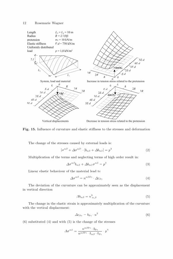
Fig. 15. Influence of curvature and elastic stiffness to the stresses and deformation
The change of the stresses caused by external loads is:
[σαβ + ∆σαβ ] · [bαβ + ∆bαβ ] = p3 (2)
Multiplication of the terms and neglecting terms of high order result in:
∆σαβbαβ + ∆bαβσαβ = p3 (3)
Linear elastic behaviour of the material lead to
∆σαβ = nαβδγ · ∆εδγ (4)
The deviation of the curvature can be approximately seen as the displacementin vertical direction
∆bαβ = u3|α,β (5)
The change in the elastic strain is approximately multiplication of the curvaturewith the vertical displacement:
∆εδγ = bδγ · u3 (6)
(6) substituted (4) and with (5) is the change of the stresses
∆σαβ =nαβδγ · bδγ
nαβδγ · bαβ · bδγ· p3
Length Lx =x Ly = 10 my
Radius R = L²/(8f)
pretension T = 10 kN/m T
Elastic stiffness E d = 750 kN/m
Uniformly distributed
load p = 1,0 kN/m²
System, load and material Increase in tension stress related to the pretension
Vertical displacements Decrease in tension stress related to the pretension
Ly
Lx
2 f 5 E d
4E d
3 E d
2E d
d
0
3R2R
R0
0
E d
2E d
3E d
4E d
5E d
3R2R
R0
+ ff- T
0
E d
2E d
3E d
4E d
5E d
3R2R
R0
On the Design Process of Tensile Structures 13
with (4), (5) and (6) in (2) follows
nαβδγbδγu3bαβ + u3|α,β · σαβ = p3
Assuming only vertical loads, allows setting the 2. term to zero and the verticaldisplacement is
u3 =1
nαβδγ · bαβ · bδγ· p3
In both equations, the change of the stresses and the vertical displacement, thedenominator is the same and a product of the elastic stiffness and the curvature ofthe surface. The lower this product is the higher the vertical deformations will be.Therefore this term describes the stiffness of the surface and is named as
D = nαβδγ · bαβ · bδγ
Expanded and the orientation of the coordinate system in direction of the prin-ciple stresses (σ12 = σ21 = 0) or principle curvature (b12 = b21 = 0) leads to:
D =n1111
R21
+n2222
R22
=R2
2 · n1111 + R21 · n2222
R21 · R2
2
Flexibility ellipsoids
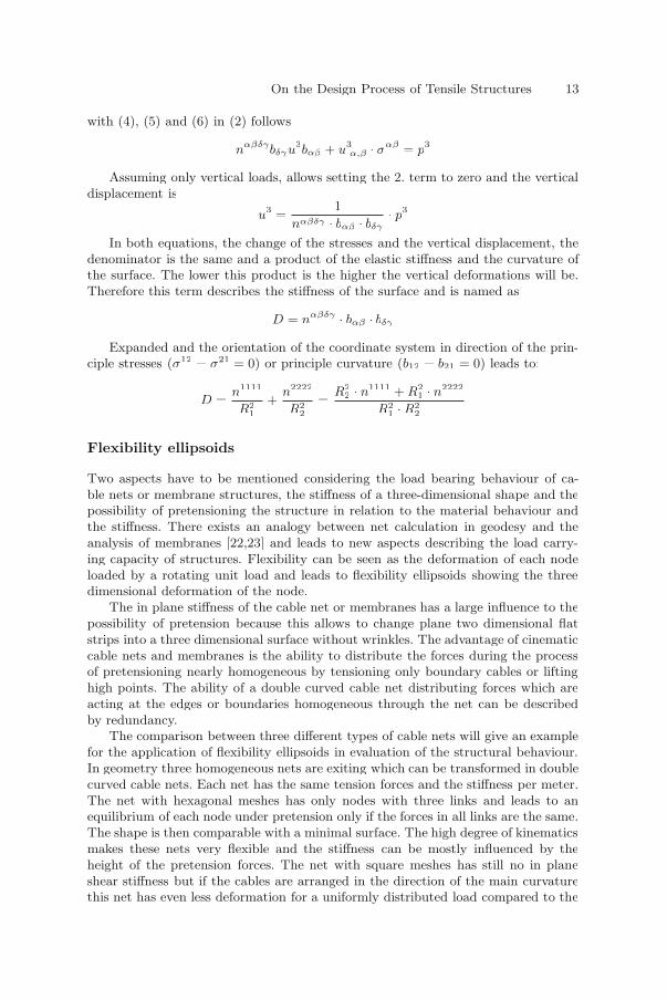
Two aspects have to be mentioned considering the load bearing behaviour of ca-ble nets or membrane structures, the stiffness of a three-dimensional shape and thepossibility of pretensioning the structure in relation to the material behaviour andthe stiffness. There exists an analogy between net calculation in geodesy and theanalysis of membranes [22,23] and leads to new aspects describing the load carry-ing capacity of structures. Flexibility can be seen as the deformation of each nodeloaded by a rotating unit load and leads to flexibility ellipsoids showing the threedimensional deformation of the node.
The in plane stiffness of the cable net or membranes has a large influence to thepossibility of pretension because this allows to change plane two dimensional flatstrips into a three dimensional surface without wrinkles. The advantage of cinematiccable nets and membranes is the ability to distribute the forces during the processof pretensioning nearly homogeneous by tensioning only boundary cables or liftinghigh points. The ability of a double curved cable net distributing forces which areacting at the edges or boundaries homogeneous through the net can be describedby redundancy.
The comparison between three different types of cable nets will give an examplefor the application of flexibility ellipsoids in evaluation of the structural behaviour.In geometry three homogeneous nets are exiting which can be transformed in doublecurved cable nets. Each net has the same tension forces and the stiffness per meter.The net with hexagonal meshes has only nodes with three links and leads to anequilibrium of each node under pretension only if the forces in all links are the same.The shape is then comparable with a minimal surface. The high degree of kinematicsmakes these nets very flexible and the stiffness can be mostly influenced by theheight of the pretension forces. The net with square meshes has still no in planeshear stiffness but if the cables are arranged in the direction of the main curvaturethis net has even less deformation for a uniformly distributed load compared to the
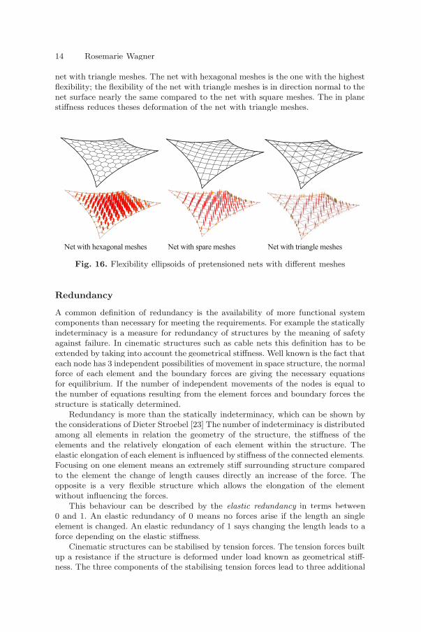
14 Rosemarie Wagner
net with triangle meshes. The net with hexagonal meshes is the one with the highestflexibility; the flexibility of the net with triangle meshes is in direction normal to thenet surface nearly the same compared to the net with square meshes. The in planestiffness reduces theses deformation of the net with triangle meshes.
Fig. 16. Flexibility ellipsoids of pretensioned nets with different meshes
Redundancy
A common definition of redundancy is the availability of more functional systemcomponents than necessary for meeting the requirements. For example the staticallyindeterminacy is a measure for redundancy of structures by the meaning of safetyagainst failure. In cinematic structures such as cable nets this definition has to beextended by taking into account the geometrical stiffness. Well known is the fact thateach node has 3 independent possibilities of movement in space structure, the normalforce of each element and the boundary forces are giving the necessary equationsfor equilibrium. If the number of independent movements of the nodes is equal tothe number of equations resulting from the element forces and boundary forces thestructure is statically determined.
Redundancy is more than the statically indeterminacy, which can be shown bythe considerations of Dieter Stroebel [23] The number of indeterminacy is distributedamong all elements in relation the geometry of the structure, the stiffness of theelements and the relatively elongation of each element within the structure. Theelastic elongation of each element is influenced by stiffness of the connected elements.Focusing on one element means an extremely stiff surrounding structure comparedto the element the change of length causes directly an increase of the force. Theopposite is a very flexible structure which allows the elongation of the elementwithout influencing the forces.
This behaviour can be described by the elastic redundancy in terms between0 and 1. An elastic redundancy of 0 means no forces arise if the length an singleelement is changed. An elastic redundancy of 1 says changing the length leads to aforce depending on the elastic stiffness.
Cinematic structures can be stabilised by tension forces. The tension forces builtup a resistance if the structure is deformed under load known as geometrical stiff-ness. The three components of the stabilising tension forces lead to three additional
Net with hexagonal meshes Net with spare meshes Net with triangle meshes

On the Design Process of Tensile Structures 15
Fig. 17. Change of forces by shortening one link of 0,5% of its length
equations for each element in a pretensioned structure and an additional geometricredundancy. The geometric redundancy of 3 says no influence of the geometric stiff-ness is required; the geometric redundancy lower than 3 describes the part of thegeometric stiffness necessary for stabilisation and higher than 3 means the elementis unstable and needed to be stabilized
For the three cable nets the elastic and geometric redundancy can be analysedfor the links and gives information to the influence of manufacturing errors, thepossibility of pretensioning and the height of the tension forces related to the defor-mation. The change of the 0,5% of the length of one link causes in the net with thehexagonal meshes no changes in the forces, shown by the elastic redundancy closeto zero. The opposite can be seen in the net with the triangle meshes, the change inthe length causes in that element an increasing force.
References
1. Grundig L (1976) Die Berechnung von vorgespannten Seilnetzen und¨Hangenetzen unter Ber¨¨ ucksichtigung ihrer topologischen und physikalischen¨Eigenschaften und der Ausgleichsrechnung. 1. SFB 64 Mitteilungen 34/1975,2. Dissertation DGK Reihe C, Nr. 216.
2. Singer P (1995) Die Berechnung von Minimalflachen, Seifenblasen, Membra-¨nen und Pneus aus geodatischer Sicht. Dissertation, Technische Universit¨¨ at¨Stuttgart, Deutsche Geodatische Kommission – Reihe C, Heft Nr. 448, M¨¨ unchen.¨
3. Bletzinger K-U (2002) Formfindung von leichen Flachentragwerken. in¨Baustatik-Baupraxis 8, Institut fur Statik, TU Braunschweig.f¨f
4. Bellmann J (1998) Membrantragwerke und Seifenhaut Unterschiede in derFormfindung. Bauingenieur, 3/98.
5. Lewis WJ, Lewis TS (1996) Application of Forminan and Dynamic Relaxationto the Form Finding of Minimal Surfaces. Journal of International Associationof space and shell structures 37(3):165–186.
6. Barnes M (1999) Form Finding and Analysis of Tension Structures by DynamicRelaxation. Int. Journal of Space Structures 14:89–104.
Elastic redundancy rErr = 2.06 Elastic redundancy rE Err = 2,33 Elastic redundancy rE Err = 2,68E
Geometric redundancy rGrr = 0,02 Geometric redundancy rG Grr = 0,20 Geometric redundancy rG Grr = 0,33G
16 Rosemarie Wagner
7. Bletzinger K-U and Wuchner R (2001) Form finding of anisotropic pre-stressed¨membrane structures. Proc. of Trends in Computational Structural Mechanics,Bregenz, Austria, May 20–23, 2001, WA Wall, K-U Bletzinger, K Schweizerhof(Eds.), CIMNE, Barcelona, Spain.
8. Moncrieff E and Topping BHV (1990) Computer Methods for the generation ofmembrane cutting pattern. Computers & Structures 37(4):441–450.
9. Ishii K (1999) Form Finding Analysis in Consideration of Cutting Patterns ofMembrane Structures. International Journal of Space Structures 14:105–119.
10. Maurin B and Motro R (1999) Cutting Pattern of Fabric membranes with Stresscomposition Method. International Journal of Space Structures 14:121–129.
11. Draft 2003. Research Project: Vorgespannte Membranen – eine interaktiveMethodik zur Auslegung von Membranen in der Luftfahrt und im Bauwesen,ISD, University of Stuttgart, Labor Blum, Stuttgart and Femscope GmbH, Sig-maringen.
12. Linkwitz K, Grundig L, Hangleiter U and Bahndorf J (1985) Mathemaisch-¨numerische Netzberechnung. In: SFB 64, Weitgespannte Flachentragwerke, Uni-¨versitat Stuttgart, Mitteilungen 72, Abschlu¨ βbericht Teilprojekt F2, Stuttgart.
13. Blum R (1974) Beitrag zur nichtlinearen Membrantheorie. SFB 64 Weitges-pannte Flachentragwerke, Universit¨ at Stuttgart, Mitteilungen 73/1985, Werner-¨Verlag, Dusseldorf.¨
14. Seifenblasen/Forming Bubbles (1988) Unter d. Leitung von Klaus Bach, FreiOtto, Mitteilungen des Instituts fur Leichte Flf¨f achentragwerke IL 18, Universit¨¨ at¨Stuttgart, Kramer Verlag Stuttgart.¨
15. Reimann K (2003) Numerische Berechnung von Minimalflachen. Internal Re-¨port, Femscope GmbH, Sigmaringen.
16. EASY – Software, Form finding, analysis and cutting pattern, Technet GmbH,Berlin.
17. Wagner R, Blum R (2004) Spannung im Tragwerk – Bauen mit Seilen undMembranen, (to be published).
18. Meffert B (1978) Mechanische Eigenschaften PVC – beschichteterPolyestergewebe, Disseration, Aachen.
19. Blum R and Bidmon W (1987) Spannungs-Dehnungs-Verhalten von Bautex-tilien. SFB 64, Weitgespannte Flachentragwerke, Universit¨¨ at Stuttgart, Mit-¨teilungen 74/1987, Werner-Verlag, Dusseldorf.¨
20. Reimann K (2003) Zur numerischen Berechnung des Spannungs-Dehnungs-Verhalten von Geweben nach Blum/Bidmon. Internal report, Femscope GmbH,Sigmaringen.
21. Zimmermann M (2000) Untersuchungen zum Unterschied zwischen derFormfindung und dem aus Bahnen zusammengefugten System bei Mem-f¨fbrantragwerken. Diplomarbeit, Institut fur Konstruktion und Entwurf II, Uni-f¨fversitat Stuttgart.¨
22. Linkwitz K (1988) Einige Bemerkungen zur Fehlerellipse und zum Fehlerellip-soid. Vermessung, Photogrammetrie, Kulturtechnik, Schweizerischer Verein furVermessungs- und Kulturtechnik (SVVK), S. 345-364. 86. Jahrgang, Heft 7.
23. Strobel D (1997) Die Anwendung der Ausgleichungsrechnung auf elastomech-¨anische Systeme. Dissertation, Technische Universitat Stuttgart, Deutsche¨Geodatisceh Kommission – Reihe C, Heft Nr. 478, M¨¨ unchen.¨
Systems for Lightweight Structure Design: theState-of-the-Art and Current Developments
Erik Moncrieff1
KurvenbauEmdener Str. 39D-10551 Berlin, [email protected]
http://www.kurvenbau.com
Summary. This paper deals with the design of lightweight structures. In partic-ular the role of computational modelling software in this process is discussed. Thestate-of-the-art is first described paying close attention to the requirements for indus-trially effective solutions. Some of the less well understood aspects of the modellingprocesses are discussed. In particular the load analysis, form-finding and cutting pat-tern generation processes are covered. The modelling of textile is addressed in detail.Approaches to the design of software design systems for lightweight structure designare discussed in the context of system flexibility and effectiveness. Finally, inter-esting applications in the field of lightweight structures arising from design systemdevelopments are highlighted.
Key words: design, lightweight structure, modelling, simulation, textile, elementtype, form-finding, geometrically non-linear structural analysis, elastically non-linearstructural analysis, cutting pattern generation, crimp, pneumatic structure, hybridstructure, adaptive design
1 Introduction
To most structural engineers and architects the design of lightweight structuresis mysterious. The objective of this paper is to summarise the state-of-the-art inlightweight structure design systems in order to highlight several important concepts.Emphasis is directed to the requirements of industrial procedures.
2 Lightweight Structure Design
2.1 Design Process
As with conventional structural engineering projects, the design process for lightweightstructures involves three key players. These are the Client, the Architect and the
17
E. Oñate and B. Kröplin (eds.), Textile Composites and Inflatable Structures, 17–28. © 2005 Springer. Printed in the Netherlands.
18 Erik Moncrieff
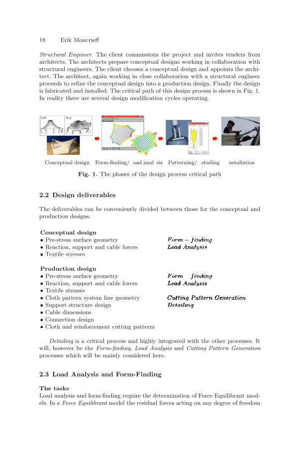
Structural Engineer. The client commissions the project and invites tenders fromarchitects. The architects prepare conceptual designs working in collaboration withstructural engineers. The client chooses a conceptual design and appoints the archi-tect. The architect, again working in close collaboration with a structural engineerproceeds to refine the conceptual design into a production design. Finally the designis fabricated and installed. The critical path of this design process is shown in Fig. 1.In reality there are several design modification cycles operating.
Conceptual design Form-finding/ oad anal sis Patterning/ etailing nstallation
Fig. 1. The phases of the design process critical path
2.2 Design deliverables
The deliverables can be conveniently divided between those for the conceptual andproduction designs.
Conceptual design• Pre-stress surface geometry Form − findingFFF −−− f dffmFormFormFormFormFormFormFormForm −−−−−−−−− gf gf gfindinggfindingfindingfindingfinding• Reaction, support and cable forces Load AnalysisALL syyLoad AnalysisAnalysisLoad AnalysisLoad AnalysisLoad AnalysisLoad Analysis• Textile stresses
Production design• Pre-stress surface geometry Form − findingFFF −−− f dffmFormFormFormFormFormFormFormForm −−−−−−−−− gf gf gfindingfindingfindingfindingfindingfinding• Reaction, support and cable forces Load AnalysisALL syyLoad AnalysissLoad AnalysisLoad AnalysisLoad AnalysisLoad Analysis• Textile stresses• Cloth pattern system line geometry Cutting Pattern GenerationC GCC nggCutting Pattern GenerationCutting Pattern GenerationCutting Pattern GenerationCutting Pattern GenerationCutting Pattern GenerationCutting Pattern Generation• Support structure design DetailingD lDD gggDetailingingDetailingDetailingDetailingDetailing• Cable dimensions• Connection design• Cloth and reinforcement cutting patterns
Detailing is a critical process and highly integrated with the other processes. Itwill, however be the Form-finding, Load Analysis and Cutting Pattern Generationprocesses which will be mainly considered here.
2.3 Load Analysis and Form-Finding
The tasksLoad analysis and form-finding require the determination of Force Equilibrant mod-els. In a Force Equilibrant model the residual forces acting on any degree of freedom

Systems for Lightweight Structure Design 19
after summing the internal and external loads acting there is zero. In the case ofcomputational load analysis the elemental forces may be calculated using severalelastic models. Similarly several methods may be used to define the elemental forcesin computational form-finding. The load intensity distribution must be estimated.
Historical developmentBefore the development of computational structural modelling, textile structureswere form-found using physical models and load analysis was performed using handcalculations. The development of linear structural analysis software had little appli-cability for the design of textile roofs due to their strong geometrical non-linearityNon-linear systems have been developed since the 1970’s and are now routinely used.
Current system configurationsToday industrial systems are broadly based on three main solver algorithms.
• Conjugate Gradient (CG)/Force Density (FD)• Dynamic Relaxation (DR)• Modified Stiffness (MS)
Developments in mainland Europe have mostly used CG/FD solvers, Britain hasconcentrated on DR, and Japan and the USA have mainly used the MS method.
Two element types are commonly used to model textile roofs. Cable net modelsusing link elements have been popular in CG/FD systems, while triangular contin-uum elements have been typically used in DR and MS systems. It is important tohighlight that the prevalence of using particular elements with particular solver al-gorithms does not have a theoretical or computational basis. CG/FD systems withtriangular continuum elements are used when appropriate, and MS and DR sys-tems can also use link elements to model textile. Appropriate element types for themodelling of lightweight structures will be discussed in Section 3.2 below.
2.4 Cutting Pattern Generation
The tasksCutting Pattern Generation is the process where two dimensional unstressed clothpolygons are created from three-dimensional doubly curved stressed surfaces. Thisinvolves the specification of seam line locations, transformation of the stressed 3Dsurfaces to stressed 2D surfaces, and compensating the stressed 2D surfaces to un-stressed 2D surfaces.
Historical developmentBefore the advent of computer modelling, textile roofs were patterned using physicalmodels. Simple triangle strip development between computer model seam lines werenext implemented and have been used successfully for medium to large structures.Distortion minimisation techniques have been adapted from map making to copewith the demands of smaller and more sensitive configurations.
Seam generationRegardless of whether physical or computational modelling is used, patterning basedon geodesic seam lines is the preferred approach. This is because geodesic lines
20 Erik Moncrieff
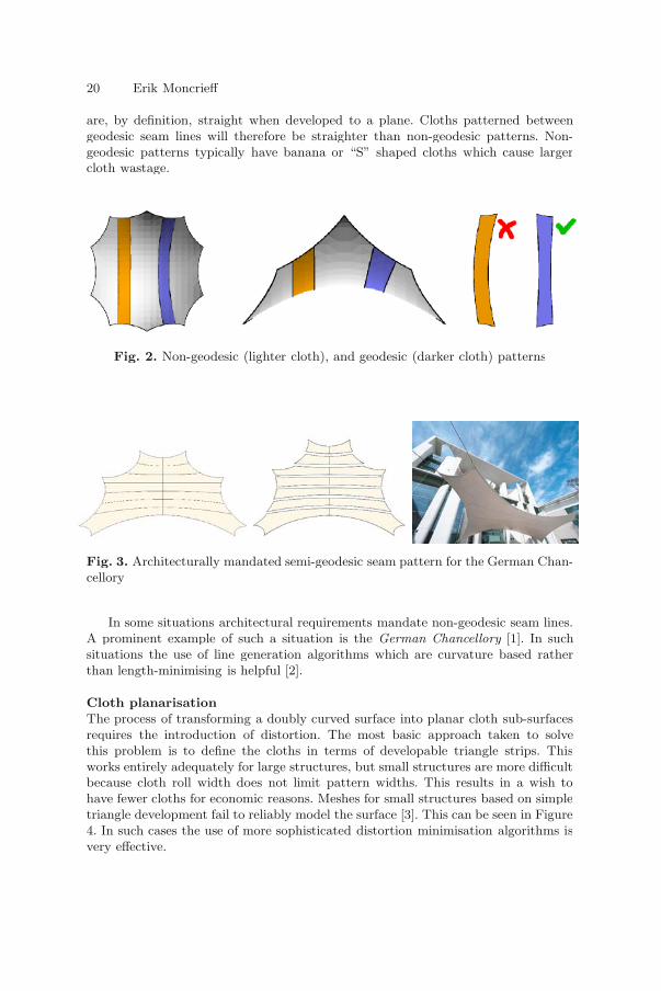
are, by definition, straight when developed to a plane. Cloths patterned betweengeodesic seam lines will therefore be straighter than non-geodesic patterns. Non-geodesic patterns typically have banana or “S” shaped cloths which cause largercloth wastage.
Fig. 2. Non-geodesic (lighter cloth), and geodesic (darker cloth) patterns
Fig. 3. Architecturally mandated semi-geodesic seam pattern for the German Chan-cellory
In some situations architectural requirements mandate non-geodesic seam lines.A prominent example of such a situation is the German Chancellory [1]. In suchsituations the use of line generation algorithms which are curvature based ratherthan length-minimising is helpful [2].
Cloth planarisationThe process of transforming a doubly curved surface into planar cloth sub-surfacesrequires the introduction of distortion. The most basic approach taken to solvethis problem is to define the cloths in terms of developable triangle strips. Thisworks entirely adequately for large structures, but small structures are more difficultbecause cloth roll width does not limit pattern widths. This results in a wish tohave fewer cloths for economic reasons. Meshes for small structures based on simpletriangle development fail to reliably model the surface [3]. This can be seen in Figure4. In such cases the use of more sophisticated distortion minimisation algorithms isvery effective.

Systems for Lightweight Structure Design 21
Fig. 4. Planarisation: (a) Large structure simple triangle development, (b) Smallstructure triangle development, (c) Small structure deformation minimising flatten-ing
2.5 Design Methodologies
Textile structures have been designed in three general ways.
Non-computational: Physical models are used to form-find the pre-stress sur-face geometry and create the cutting patterns. Simplified “hand calculations”are used to predict structural response.
Non-specialised software: Non-equilibrium computational modelling soft-ware, such as 3ds max, is used to generate the pre-stress surface geometryand cutting pattern generation. Standard FE structural analysis software isused to perform load analysis.
Specialised software: Lightweight structure task-specific equilibrium basedcomputational modelling software is used to perform form-finding, load anal-ysis and cutting pattern generation.
The non-computational method has the advantages that it is intuitive, the formcan be realised, it can be implemented with low initial investment, and modificationof conceptual forms is quick and simple. It suffers from its lack of computationalnon-linear structural analysis, low precision and lack of computational mesh forrendering. Its slowness, particularly with respect to making modifications to theproduction form and cutting patterns, makes it operationally expensive.
Using the non-specialised software method leverages existing CAD and analysissoftware skills and provides many sophisticated geometric tools. With few excep-tions, the forms generated are, however, not force equilibrant. Consequently theycan not necessarily be realised with a tensile surface. Lack of integration betweenthe mesh generation and analysis leads to slow design modification cycles. Conven-tional FE software is often inappropriate for use with textile models. In particular,convergence problems are usually experienced by standard FE systems when dealingwith textile slackening on-off non-linearity.
Specialist textile structure software systems quickly provides high confidence,high precision, integrated solutions. Initial investment is higher but when designvolume is adequate, per-design costs are low. It is therefore the recommended methodfor production design. Having said that it is important to stress that the continueduse of physical modelling during the conceptual modelling phase should always beencouraged.
22 Erik Moncrieff
3 Modelling Textile
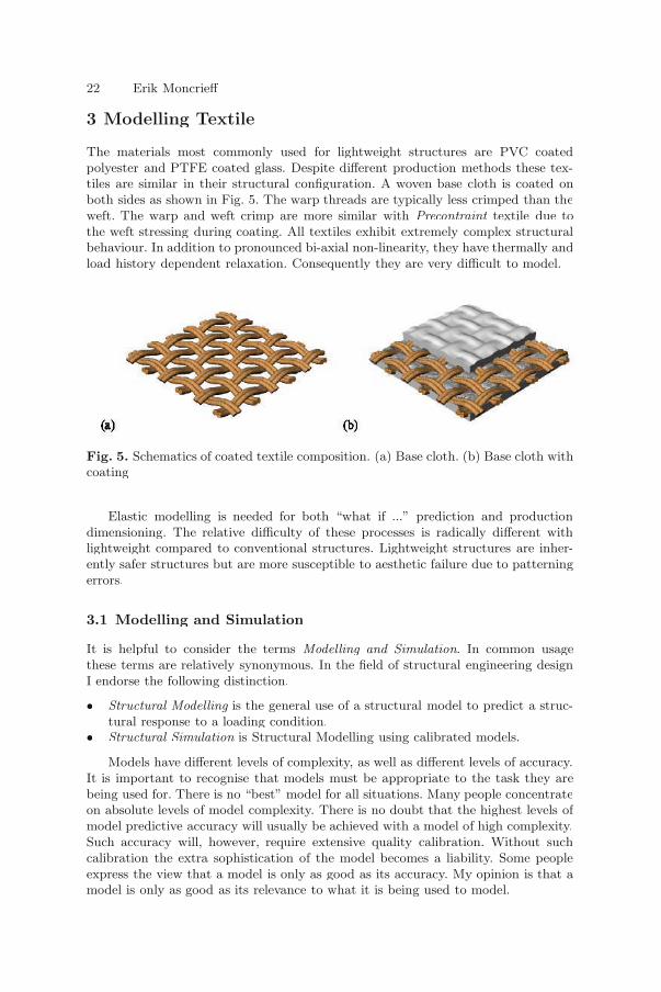
The materials most commonly used for lightweight structures are PVC coatedpolyester and PTFE coated glass. Despite different production methods these tex-tiles are similar in their structural configuration. A woven base cloth is coated onboth sides as shown in Fig. 5. The warp threads are typically less crimped than theweft. The warp and weft crimp are more similar with Precontraint textile due tothe weft stressing during coating. All textiles exhibit extremely complex structuralbehaviour. In addition to pronounced bi-axial non-linearity, they have thermally andload history dependent relaxation. Consequently they are very difficult to model.
Fig. 5. Schematics of coated textile composition. (a) Base cloth. (b) Base cloth withcoating
Elastic modelling is needed for both “what if ...” prediction and productiondimensioning. The relative difficulty of these processes is radically different withlightweight compared to conventional structures. Lightweight structures are inher-ently safer structures but are more susceptible to aesthetic failure due to patterningerrors.
3.1 Modelling and Simulation
It is helpful to consider the terms Modelling and Simulation. In common usagethese terms are relatively synonymous. In the field of structural engineering designI endorse the following distinction.
• Structural Modelling is the general use of a structural model to predict a struc-tural response to a loading condition.
• Structural Simulation is Structural Modelling using calibrated models.
Models have different levels of complexity, as well as different levels of accuracy.It is important to recognise that models must be appropriate to the task they arebeing used for. There is no “best” model for all situations. Many people concentrateon absolute levels of model complexity. There is no doubt that the highest levels ofmodel predictive accuracy will usually be achieved with a model of high complexity.Such accuracy will, however, require extensive quality calibration. Without suchcalibration the extra sophistication of the model becomes a liability. Some peopleexpress the view that a model is only as good as its accuracy. My opinion is that amodel is only as good as its relevance to what it is being used to model.
Systems for Lightweight Structure Design 23
It is a remarkable fact that so little measurement of lightweight structures hasbeen conducted. In particular almost no textile surface measurements have beenperformed. We advocate the use of non-contact photogrammetry for strain mea-surement of in-situ textile structures [4].
3.2 Element Types for Textile Modeling
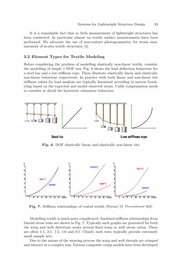
Before considering the problem of modelling elastically non-linear textile, considerthe modelling of simple 1 DOF ties. Fig. 6 shows the load deflection behaviour fora steel bar and a low stiffness rope. These illustrate elastically linear and elasticallynon-linear behaviour respectively. In practice with both linear and non-linear tiesstiffness values for load analysis are typically linearised according to narrow brack-eting based on the expected and model observed strain. Cable compensation needsto consider in detail the hysteretic relaxation behaviour.
Fig. 6. DOF elastically linear and elastically non-linear ties
Fig. 7. Stiffness relationships of coated textile (Ferrari [5] Precontraint 502)
Modelling textile is much more complicated. Sanitised stiffness relationships frombiaxial stress tests are shown in Fig. 7. Typically such graphs are generated for boththe warp and weft directions under several fixed warp to weft stress ratios. Theseare often 1:1, 2:1, 1:2, 1:0 and 0:1. Clearly such tests typically provide extremelysmall sample sets.
Due to the nature of the weaving process the warp and weft threads are crimpedand interact in a complex way. Various composite crimp models have been developed