tetrix 351 ac/dc aw fw;tetrix 451 ac/dc aw fw ... - … * *for details visit . general instructions...
TRANSCRIPT

Operating instructions
EN
Welding machines and accessories
Tetrix 351 AC/DC AW FW Tetrix 451 AC/DC AW FW Tetrix 551 AC/DC AW FW
099-000115-EW501 Observe additional system documents! 17.06.2015
Register nowand benefit!Jetzt Registrierenund Profitieren!
www.ewm-group.com
*For
det
ails
vis
itw
ww
.ew
m-g
roup
.com
*

General instructions
CAUTION
Read the operating instructions!
The operating instructions provide an introduction to the safe use of the products.
• Read the operating instructions for all system components!
• Observe accident prevention regulations!
• Observe all local regulations!
• Confirm with a signature where appropriate.
In the event of queries on installation, commissioning, operation or special conditions at the
installation site, or on usage, please contact your sales partner or our customer service
department on +49 2680 181-0.
A list of authorised sales partners can be found at www.ewm-group.com.
Liability relating to the operation of this equipment is restricted solely to the function of the
equipment. No other form of liability, regardless of type, shall be accepted. This exclusion of
liability shall be deemed accepted by the user on commissioning the equipment.
The manufacturer is unable to monitor whether or not these instructions or the conditions and
methods are observed during installation, operation, usage and maintenance of the equipment.
An incorrectly performed installation can result in material damage and injure persons as a
result. For this reason, we do not accept any responsibility or liability for losses, damages or
costs arising from incorrect installation, improper operation or incorrect usage and maintenance
or any actions connected to this in any way.
© EWM AG · Dr. Günter-Henle-Str. 8 · D-56271 Mündersbach, Germany
The copyright to this document remains the property of the manufacturer.
Reprinting, including extracts, only permitted with written approval.
The content of this document has been prepared and reviewed with all reasonable care. The information
provided is subject to change, errors excepted.

Contents Notes on the use of these operating instructions
099-000115-EW501
17.06.2015 3
1 Contents
1 Contents .................................................................................................................................................. 3
2 Safety instructions ................................................................................................................................. 8 2.1 Notes on the use of these operating instructions .......................................................................... 8 2.2 Explanation of icons ....................................................................................................................... 9 2.3 General ........................................................................................................................................ 10 2.4 Transport and installation ............................................................................................................ 14
2.4.1 Lifting by crane ............................................................................................................. 15 2.4.2 Ambient conditions ....................................................................................................... 16
2.4.2.1 In operation ................................................................................................... 16 2.4.2.2 Transport and storage ................................................................................... 16
3 Intended use ......................................................................................................................................... 17 3.1 Applications .................................................................................................................................. 17
3.1.1 TIG welding .................................................................................................................. 17 3.1.1.1 TIG hot wire welding ..................................................................................... 17 3.1.1.2 TIG cold wire welding .................................................................................... 17 3.1.1.3 TIG activArc welding ..................................................................................... 17 3.1.1.4 spotArc .......................................................................................................... 17 3.1.1.5 Spotmatic ...................................................................................................... 17
3.1.2 MMA welding ................................................................................................................ 17 3.2 Use and operation solely with the following machines ................................................................ 18 3.3 Documents which also apply ....................................................................................................... 18
3.3.1 Warranty ....................................................................................................................... 18 3.3.2 Declaration of Conformity ............................................................................................. 18 3.3.3 Welding in environments with increased electrical hazards ......................................... 18 3.3.4 Service documents (spare parts and circuit diagrams) ................................................ 18 3.3.5 Calibration/Validation ................................................................................................... 18
4 Machine description – quick overview .............................................................................................. 19 4.1 System overview .......................................................................................................................... 19 4.2 Tetrix 351 AC/DC AW .................................................................................................................. 20 4.3 Front view .................................................................................................................................... 20 4.4 Rear view ..................................................................................................................................... 22 4.5 Tetrix 451, 551 AC/DC AW .......................................................................................................... 24 4.6 Front view .................................................................................................................................... 24 4.7 Rear view ..................................................................................................................................... 26 4.8 Machine control – Operating elements ........................................................................................ 28
4.8.1 Function sequence ....................................................................................................... 30
5 Design and function ............................................................................................................................. 32 5.1 General ........................................................................................................................................ 32 5.2 Machine cooling ........................................................................................................................... 33 5.3 Workpiece lead, general .............................................................................................................. 33 5.4 Notes on the installation of welding current leads ....................................................................... 34 5.5 Mains connection ......................................................................................................................... 36
5.5.1 Mains configuration ...................................................................................................... 36 5.6 Welding torch cooling system ...................................................................................................... 37
5.6.1 List of coolants .............................................................................................................. 37 5.6.2 Maximal hose package length ...................................................................................... 37 5.6.3 Adding coolant .............................................................................................................. 38
5.7 Shielding gas supply (shielding gas cylinder for welding machine) ............................................. 39 5.7.1 Connection ................................................................................................................... 39
5.8 TIG welding .................................................................................................................................. 40 5.8.1 TIG cold or hot wire welding ......................................................................................... 40 5.8.2 Setting the shielding gas quantity ................................................................................. 40 5.8.3 Gas test ........................................................................................................................ 40 5.8.4 “Purge hose package” function .................................................................................... 40
5.9 TIG cold wire welding................................................................................................................... 41 5.9.1 Connection plan ............................................................................................................ 41

Contents Notes on the use of these operating instructions
4 099-000115-EW501
17.06.2015
5.9.2 Legend .......................................................................................................................... 42 5.9.3 Installation ..................................................................................................................... 42 5.9.4 Intermediate hose package connection ........................................................................ 43
5.10 TIG hot wire welding .................................................................................................................... 45 5.10.1 Connection plan ............................................................................................................ 45
5.10.1.1 Legend........................................................................................................... 46 5.10.2 Installation ..................................................................................................................... 47
5.10.2.1 Wire feed unit ................................................................................................ 47 5.10.2.2 Power source for hot wire welding ................................................................ 48
5.10.3 Intermediate hose package connection ........................................................................ 50 5.11 Configuring the welding machine for mechanical arc fusion welding .......................................... 52
5.11.1 Selecting a welding task by means of the JOB list ....................................................... 53 5.11.2 Select wire speed operating mode (KORREKTUR / MANUELL) ................................. 53 5.11.3 Setting the welding current and wire speed.................................................................. 53 5.11.4 Function sequences/operating modes .......................................................................... 54
5.11.4.1 Explanation of symbols ................................................................................. 54 5.11.4.2 Non-latched mode ......................................................................................... 55 5.11.4.3 3-cycle operation ........................................................................................... 56 5.11.4.4 Latched mode ................................................................................................ 56
5.12 TIG welding .................................................................................................................................. 57 5.12.1 Welding torch and workpiece line connection .............................................................. 57
5.12.1.1 Torch connection options and pin assignments ............................................ 58 5.13 TIG Synergic operating principle .................................................................................................. 59
5.13.1 Synergic parameter setting in the functional sequence ................................................ 60 5.13.2 Conventional parameter setting in the functional sequence ......................................... 60
5.13.2.1 Set the operating principle (conventional/synergic) ...................................... 61 5.13.3 Select welding task ....................................................................................................... 62 5.13.4 Select welding current .................................................................................................. 63 5.13.5 Welding data display ..................................................................................................... 63
5.13.5.1 Welding current display (ignition, secondary, end and hotstart currents) ..... 64 5.13.6 Expert menu (TIG) ........................................................................................................ 65
5.13.6.1 Welding parameter setting ............................................................................ 65 5.13.7 Arc ignition .................................................................................................................... 66
5.13.7.1 HF ignition ..................................................................................................... 66 5.13.7.2 Liftarc ignition ................................................................................................ 66 5.13.7.3 Automatic cut-out .......................................................................................... 66
5.13.8 Optimising the ignition characteristics for pure tungsten electrodes ............................ 67 5.13.9 Optimal and fast spherical cup formation ..................................................................... 67 5.13.10 Function sequences/operating modes .......................................................................... 68
5.13.10.1 Explanation of symbols ................................................................................. 68 5.13.10.2 Non-latched mode ......................................................................................... 69 5.13.10.3 Latched mode ................................................................................................ 70 5.13.10.4 spotArc .......................................................................................................... 71 5.13.10.5 Spotmatic ...................................................................................................... 73 5.13.10.6 Non-latched operation, version C .................................................................. 74
5.13.11 Pulses, function sequences .......................................................................................... 75 5.13.11.1 TIG pulses – non-latched operation .............................................................. 75 5.13.11.2 TIG pulses - latched operation ...................................................................... 75
5.13.12 Pulse variants ............................................................................................................... 76 5.13.12.1 Pulses (thermal pulses) ................................................................................. 76 5.13.12.2 KHz pulses (metallurgic pulses) .................................................................... 77 5.13.12.3 Automated pulses .......................................................................................... 77 5.13.12.4 AC pulses ...................................................................................................... 78 5.13.12.5 AC special ..................................................................................................... 78
5.13.13 TIG activArc welding ..................................................................................................... 79 5.13.14 TIG antistick .................................................................................................................. 79 5.13.15 Welding torch (operating variants) ................................................................................ 80
5.13.15.1 Tap torch trigger (tapping function) ............................................................... 80 5.13.16 Torch mode and up/down speed setting ...................................................................... 81
5.13.16.1 Standard TIG torch (5-pole) .......................................................................... 82
Contents Notes on the use of these operating instructions
099-000115-EW501
17.06.2015 5
5.13.16.2 TIG up/down torch (8-pole) ........................................................................... 84 5.13.16.3 Potentiometer torch (8-pole) ......................................................................... 86 5.13.16.4 Configuring the TIG potentiometer torch connection .................................... 87 5.13.16.5 RETOX TIG torch (12-pole) .......................................................................... 88 5.13.16.6 Specifying max. no. of accessible JOBs ....................................................... 89 5.13.16.7 Setting the first increment ............................................................................. 90
5.14 MMA welding ............................................................................................................................... 91 5.14.1 Connecting the electrode holder and workpiece lead .................................................. 91 5.14.2 Select welding task ....................................................................................................... 92 5.14.3 Welding current polarity reversal (polarity reversal) ..................................................... 92 5.14.4 Selection and adjustment ............................................................................................. 92 5.14.5 Frequency and balance setting .................................................................................... 93 5.14.6 Hotstart ......................................................................................................................... 93
5.14.6.1 Hotstart current ............................................................................................. 93 5.14.6.2 Hotstart time .................................................................................................. 94
5.14.7 Arcforce ........................................................................................................................ 94 5.14.8 Antistick ........................................................................................................................ 94 5.14.9 MMA pulse welding in the vertical up position (PF) ..................................................... 95
5.15 Welding programs ........................................................................................................................ 96 5.15.1 Selection and adjustment ............................................................................................. 97 5.15.2 Specifying max. no. of accessible programs ................................................................ 97 5.15.3 Example "Program with synergetic setting".................................................................. 98 5.15.4 Example "Program with conventional setting" .............................................................. 98 5.15.5 Accessories for switching over programs ..................................................................... 98
5.16 Organising welding tasks (Mode "JOB Manager") ...................................................................... 99 5.16.1 Explanation of symbols ................................................................................................ 99 5.16.2 Creating a new JOB in the memory or copying a JOB ............................................... 100 5.16.3 Loading an existing JOB from the free memory ......................................................... 101 5.16.4 Resetting an existing JOB to the factory setting (Reset JOB) ................................... 101 5.16.5 Resetting JOBs 1-128 to the factory setting (Reset All JOBs) ................................... 102 5.16.6 Exit JOB Manager without changes ........................................................................... 102
5.17 Remote control ........................................................................................................................... 103 5.17.1 Manual remote control RT1 19POL ............................................................................ 103 5.17.2 RTG1 19POL manual remote control ......................................................................... 103 5.17.3 Manual remote control RTP1 19POL ......................................................................... 103 5.17.4 Manual remote control RTP2 19POL ......................................................................... 103 5.17.5 RTP3 spotArc 19POL manual remote control ............................................................ 103 5.17.6 Manual remote control RT AC 1 19POL .................................................................... 103 5.17.7 Manual remote control RT PWS 1 19POL ................................................................. 104 5.17.8 Foot-operated remote control RTF1 19POL 5 M / RTF2 19POL 5 M ........................ 104
5.17.8.1 Ramp function foot-operated remote control RTF 1 / RTF 2 ...................... 105 5.18 Simultaneous welding on both sides, synchronisation types .................................................... 106
5.18.1 Synchronisation via mains voltage (50Hz / 60Hz) ...................................................... 106 5.18.2 Synchronisation via cable (frequency 50Hz to 200Hz) .............................................. 107
5.19 Interfaces for automation ........................................................................................................... 108 5.19.1 TIG interface for mechanised welding ........................................................................ 108 5.19.2 Remote control connection socket, 19-pole ............................................................... 109
5.20 Protecting welding parameters from unauthorised access ........................................................ 110 5.21 PC interface ............................................................................................................................... 110 5.22 Machine configuration menu ...................................................................................................... 110
5.22.1 Selecting, changing and saving parameters .............................................................. 110 5.22.2 Aligning the cable resistance ...................................................................................... 116 5.22.3 Power-saving mode (Standby) ................................................................................... 117
6 Maintenance, care and disposal ....................................................................................................... 118 6.1 Maintenance work ...................................................................................................................... 118 6.2 General ...................................................................................................................................... 118 6.3 Maintenance work, intervals ...................................................................................................... 118
6.3.1 Daily maintenance tasks ............................................................................................ 118 6.3.1.1 Visual inspection ......................................................................................... 118 6.3.1.2 Functional test ............................................................................................. 118

Contents Notes on the use of these operating instructions
6 099-000115-EW501
17.06.2015
6.3.2 Monthly maintenance tasks ........................................................................................ 119 6.3.2.1 Visual inspection ......................................................................................... 119 6.3.2.2 Functional test ............................................................................................. 119
6.3.3 Annual test (inspection and testing during operation) ................................................ 119 6.4 Disposing of equipment .............................................................................................................. 120
6.4.1 Manufacturer's declaration to the end user ................................................................ 120 6.5 Meeting the requirements of RoHS ............................................................................................ 120
7 Rectifying faults.................................................................................................................................. 121 7.1 Checklist for rectifying faults ...................................................................................................... 121 7.2 Warnings (power source) ........................................................................................................... 123 7.3 Error messages (power source) ................................................................................................. 124 7.4 Resetting welding parameters to the factory settings ................................................................ 126 7.5 Display machine control software version .................................................................................. 127 7.6 General operating problems ...................................................................................................... 127
7.6.1 Interface for automated welding ................................................................................. 127 7.7 Vent coolant circuit ..................................................................................................................... 128
8 Technical data..................................................................................................................................... 129 8.1 Tetrix 351 AC/DC AW ................................................................................................................ 129 8.2 Tetrix 451 AC/DC AW ................................................................................................................ 130 8.3 Tetrix 551 AC/DC AW ................................................................................................................ 131
9 Accessories ........................................................................................................................................ 132 9.1 System components ................................................................................................................... 132 9.2 Options ....................................................................................................................................... 132
9.2.1 Tetrix 351 AC/DC ........................................................................................................ 132 9.2.2 Tetrix 451, 551 AC/DC ................................................................................................ 132 9.2.3 Tetrix 351, 451, 551 AC/DC ....................................................................................... 132
9.3 General accessories .................................................................................................................. 133 9.4 Remote controls and accessories .............................................................................................. 133 9.5 Computer communication .......................................................................................................... 133
10 Appendix A .......................................................................................................................................... 134 10.1 JOB-List...................................................................................................................................... 134
11 Appendix B .......................................................................................................................................... 138 11.1 Overview of EWM branches....................................................................................................... 138

Contents Notes on the use of these operating instructions
099-000115-EW501
17.06.2015 7
Safety instructions Notes on the use of these operating instructions
8 099-000115-EW501
17.06.2015
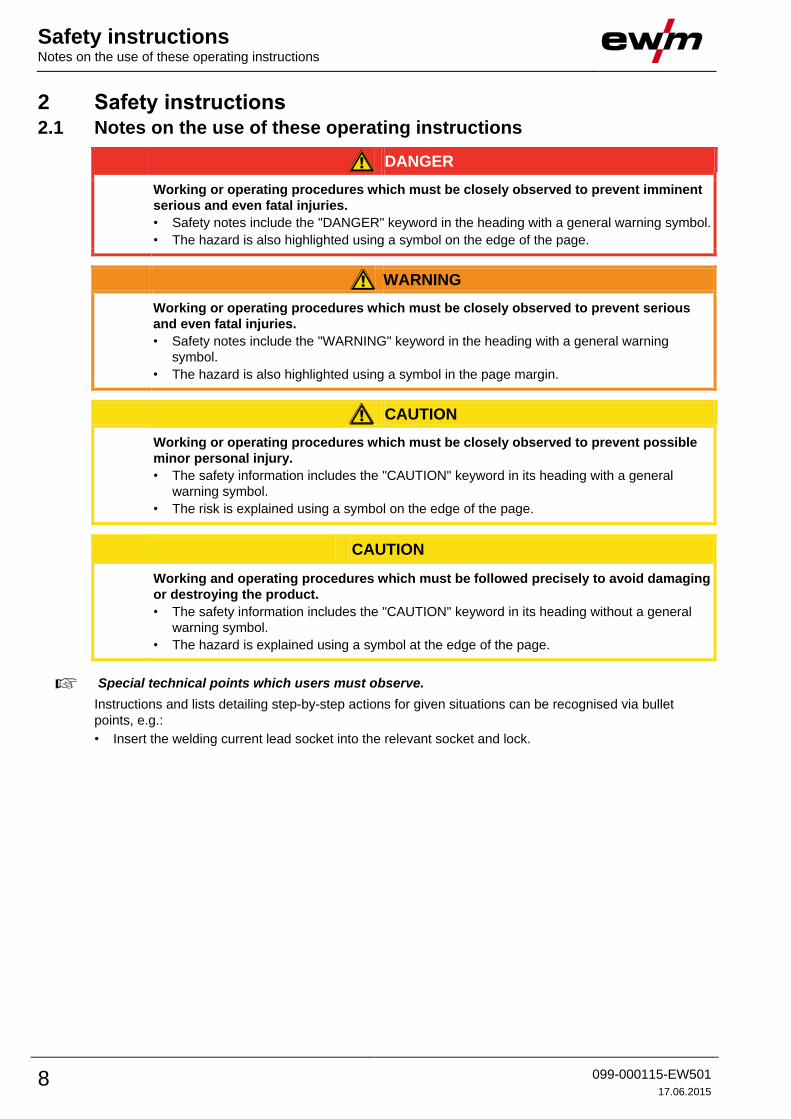
2 Safety instructions 2.1 Notes on the use of these operating instructions
DANGER
Working or operating procedures which must be closely observed to prevent imminent
serious and even fatal injuries.
• Safety notes include the "DANGER" keyword in the heading with a general warning symbol.
• The hazard is also highlighted using a symbol on the edge of the page.
WARNING
Working or operating procedures which must be closely observed to prevent serious
and even fatal injuries.
• Safety notes include the "WARNING" keyword in the heading with a general warning
symbol.
• The hazard is also highlighted using a symbol in the page margin.
CAUTION
Working or operating procedures which must be closely observed to prevent possible
minor personal injury.
• The safety information includes the "CAUTION" keyword in its heading with a general
warning symbol.
• The risk is explained using a symbol on the edge of the page.
CAUTION
Working and operating procedures which must be followed precisely to avoid damaging
or destroying the product.
• The safety information includes the "CAUTION" keyword in its heading without a general
warning symbol.
• The hazard is explained using a symbol at the edge of the page.
Special technical points which users must observe.
Instructions and lists detailing step-by-step actions for given situations can be recognised via bullet
points, e.g.:
• Insert the welding current lead socket into the relevant socket and lock.

Safety instructions Explanation of icons
099-000115-EW501
17.06.2015 9
2.2 Explanation of icons
Symbol Description
Special technical points which users must observe.
Correct
Wrong
Press
Do not press
Press and keep pressed
Turn
Switch
Switch off machine
Switch on machine
ENTERENTER
ENTER (enter the menu)
NAVIGATION
NAVIGATION (Navigating in the menu)
EXIT
EXIT (Exit the menu)
4 s
Time display (example: wait 4s/press)
Interruption in the menu display (other setting options possible)
Tool not required/do not use
Tool required/use

Safety instructions General
10 099-000115-EW501
17.06.2015
2.3 General
DANGER
Electric shock!
Welding machines use high voltages which can result in potentially fatal electric shocks
and burns on contact. Even low voltages can cause you to get a shock and lead to
accidents.
• Do not touch any live parts in or on the machine!
• Connection cables and leads must be free of faults!
• Switching off alone is not sufficient!
• Place welding torch and stick electrode holder on an insulated surface!
• The unit should only be opened by specialist staff after the mains plug has been
unplugged!
• Only wear dry protective clothing!
• Wait for 4 minutes until the capacitors have discharged!
Electromagnetic fields!
The power source may cause electrical or electromagnetic fields to be produced which
could affect the correct functioning of electronic equipment such as IT or CNC devices,
telecommunication lines, power cables, signal lines and pacemakers.
• Observe the maintenance instructions - See 6 Maintenance, care and disposal chapter!
• Unwind welding leads completely!
• Shield devices or equipment sensitive to radiation accordingly!
• The correct functioning of pacemakers may be affected (obtain advice from a doctor if
necessary).
Do not carry out any unauthorised repairs or modifications!
To avoid injury and equipment damage, the unit must only be repaired or modified by
specialist, skilled persons!
The warranty becomes null and void in the event of unauthorised interference.
• Appoint only skilled persons for repair work (trained service personnel)!
WARNING
Risk of accidents if these safety instructions are not observed!
Non-observance of these safety instructions is potentially fatal!
• Carefully read the safety information in this manual!
• Observe the accident prevention regulations in your country.
• Inform persons in the working area that they must observe the regulations!
Risk of injury due to radiation or heat!
Arc radiation results in injury to skin and eyes.
Contact with hot workpieces and sparks results in burns.
• Use welding shield or welding helmet with the appropriate safety level (depending on the
application)!
• Wear dry protective clothing (e.g. welding shield, gloves, etc.) according to the relevant
regulations in the country in question!
• Protect persons not involved in the work against arc beams and the risk of glare using
safety curtains!

Safety instructions General
099-000115-EW501
17.06.2015 11
WARNING
Explosion risk!
Apparently harmless substances in closed containers may generate excessive pressure
when heated.
• Move containers with inflammable or explosive liquids away from the working area!
• Never heat explosive liquids, dusts or gases by welding or cutting!
Smoke and gases!
Smoke and gases can lead to breathing difficulties and poisoning. In addition, solvent
vapour (chlorinated hydrocarbon) may be converted into poisonous phosgene due to
the ultraviolet radiation of the arc!
• Ensure that there is sufficient fresh air!
• Keep solvent vapour away from the arc beam field!
• Wear suitable breathing apparatus if appropriate!
Fire hazard!
Flames may arise as a result of the high temperatures, stray sparks, glowing-hot parts
and hot slag produced during the welding process.
Stray welding currents can also result in flames forming!
• Check for fire hazards in the working area!
• Do not carry any easily flammable objects such as matches or lighters.
• Keep appropriate fire extinguishing equipment to hand in the working area!
• Thoroughly remove any residue of flammable substances from the workpiece before
starting welding.
• Only continue work on welded workpieces once they have cooled down.
Do not allow to come into contact with flammable material!
• Connect welding leads correctly!
Danger when coupling multiple power sources!
Coupling multiple power sources in parallel or in series has to be carried out by
qualified personnel and in accordance with the manufacturer's guidelines. Before
bringing the power sources into service for arc welding operations, a test has to verify
that they cannot exceed the maximum allowed open circuit voltage.
• Connection of the machine may be carried out by qualified personnel only!
• When decommissioning individual power sources, all mains and welding current leads have
to be safely disconnected from the welding system as a whole. (Danger due to inverse
voltages!)
• Do not couple welding machines with pole reversing switch (PWS series) or machines for
AC welding, as a minor error in operation can cause the welding voltages to be combined.
CAUTION
Noise exposure!
Noise exceeding 70 dBA can cause permanent hearing damage!
• Wear suitable ear protection!
• Persons located within the working area must wear suitable ear protection!
Safety instructions General
12 099-000115-EW501
17.06.2015
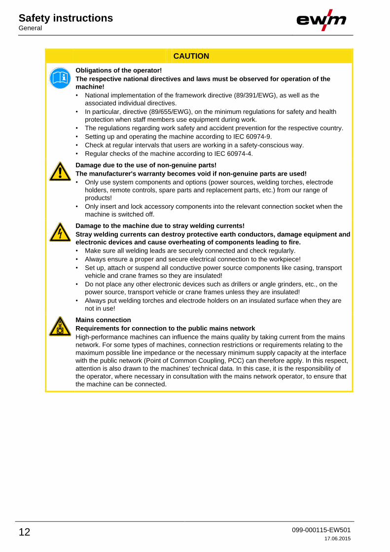
CAUTION
Obligations of the operator!
The respective national directives and laws must be observed for operation of the
machine!
• National implementation of the framework directive (89/391/EWG), as well as the
associated individual directives.
• In particular, directive (89/655/EWG), on the minimum regulations for safety and health
protection when staff members use equipment during work.
• The regulations regarding work safety and accident prevention for the respective country.
• Setting up and operating the machine according to IEC 60974-9.
• Check at regular intervals that users are working in a safety-conscious way.
• Regular checks of the machine according to IEC 60974-4.
Damage due to the use of non-genuine parts!
The manufacturer's warranty becomes void if non-genuine parts are used!
• Only use system components and options (power sources, welding torches, electrode
holders, remote controls, spare parts and replacement parts, etc.) from our range of
products!
• Only insert and lock accessory components into the relevant connection socket when the
machine is switched off.
Damage to the machine due to stray welding currents!
Stray welding currents can destroy protective earth conductors, damage equipment and
electronic devices and cause overheating of components leading to fire.
• Make sure all welding leads are securely connected and check regularly.
• Always ensure a proper and secure electrical connection to the workpiece!
• Set up, attach or suspend all conductive power source components like casing, transport
vehicle and crane frames so they are insulated!
• Do not place any other electronic devices such as drillers or angle grinders, etc., on the
power source, transport vehicle or crane frames unless they are insulated!
• Always put welding torches and electrode holders on an insulated surface when they are
not in use!
Mains connection
Requirements for connection to the public mains network
High-performance machines can influence the mains quality by taking current from the mains
network. For some types of machines, connection restrictions or requirements relating to the
maximum possible line impedance or the necessary minimum supply capacity at the interface
with the public network (Point of Common Coupling, PCC) can therefore apply. In this respect,
attention is also drawn to the machines' technical data. In this case, it is the responsibility of
the operator, where necessary in consultation with the mains network operator, to ensure that
the machine can be connected.

Safety instructions General
099-000115-EW501
17.06.2015 13
CAUTION
EMC Machine Classification
In accordance with IEC 60974-10, welding machines are grouped in two electromagnetic
compatibility classes - See 8 Technical data chapter:
Class A machines are not intended for use in residential areas where the power supply comes
from the low-voltage public mains network. When ensuring the electromagnetic compatibility of
class A machines, difficulties can arise in these areas due to interference not only in the supply
lines but also in the form of radiated interference.
Class B machines fulfil the EMC requirements in industrial as well as residential areas,
including residential areas connected to the low-voltage public mains network.
Setting up and operating
When operating arc welding systems, in some cases, electro-magnetic interference can occur
although all of the welding machines comply with the emission limits specified in the standard.
The user is responsible for any interference caused by welding.
In order to evaluate any possible problems with electromagnetic compatibility in the
surrounding area, the user must consider the following: (see also EN 60974-10 Appendix A)
• Mains, control, signal and telecommunication lines
• Radios and televisions
• Computers and other control systems
• Safety equipment
• The health of neighbouring persons, especially if they have a pacemaker or wear a hearing
aid
• Calibration and measuring equipment
• The immunity to interference of other equipment in the surrounding area
• The time of day at which the welding work must be carried out
Recommendations for reducing interference emission
• Mains connection, e.g. additional mains filter or shielding with a metal tube
• Maintenance of the arc welding equipment
• Welding leads should be as short as possible and run closely together along the ground
• Potential equalization
• Earthing of the workpiece. In cases where it is not possible to earth the workpiece directly,
it should be connected by means of suitable capacitors.
• Shielding from other equipment in the surrounding area or the entire welding system
Safety instructions Transport and installation
14 099-000115-EW501
17.06.2015
2.4 Transport and installation
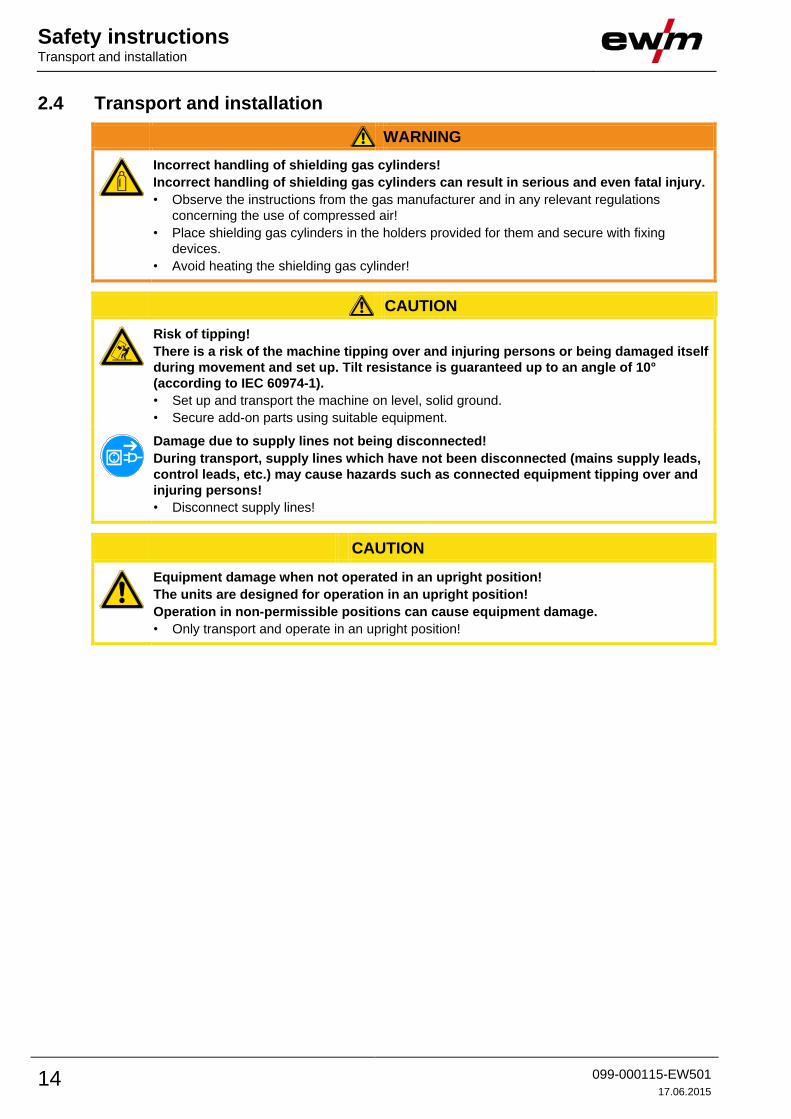
WARNING
Incorrect handling of shielding gas cylinders!
Incorrect handling of shielding gas cylinders can result in serious and even fatal injury.
• Observe the instructions from the gas manufacturer and in any relevant regulations
concerning the use of compressed air!
• Place shielding gas cylinders in the holders provided for them and secure with fixing
devices.
• Avoid heating the shielding gas cylinder!
CAUTION
Risk of tipping!
There is a risk of the machine tipping over and injuring persons or being damaged itself
during movement and set up. Tilt resistance is guaranteed up to an angle of 10°
(according to IEC 60974-1).
• Set up and transport the machine on level, solid ground.
• Secure add-on parts using suitable equipment.
Damage due to supply lines not being disconnected!
During transport, supply lines which have not been disconnected (mains supply leads,
control leads, etc.) may cause hazards such as connected equipment tipping over and
injuring persons!
• Disconnect supply lines!
CAUTION
Equipment damage when not operated in an upright position!
The units are designed for operation in an upright position!
Operation in non-permissible positions can cause equipment damage.
• Only transport and operate in an upright position!
Safety instructions Transport and installation
099-000115-EW501
17.06.2015 15
2.4.1 Lifting by crane
DANGER
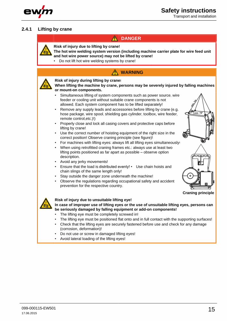
Risk of injury due to lifting by crane!
The hot wire welding system version (including machine carrier plate for wire feed unit
and hot wire power source) may not be lifted by crane!
• Do not lift hot wire welding systems by crane!
WARNING
Risk of injury during lifting by crane!
When lifting the machine by crane, persons may be severely injured by falling machines
or mount-on components.
• Simultaneous lifting of system components such as power source, wire
feeder or cooling unit without suitable crane components is not
allowed. Each system component has to be lifted separately!
• Remove any supply leads and accessories before lifting by crane (e.g.
hose package, wire spool, shielding gas cylinder, toolbox, wire feeder,
remote control,etc.)!)
• Properly close and lock all casing covers and protective caps before
lifting by crane!
• Use the correct number of hoisting equipment of the right size in the
correct position! Observe craning principle (see figure)!
• For machines with lifting eyes: always lift all lifting eyes simultaneously!
• When using retrofitted craning frames etc.: always use at least two
lifting points positioned as far apart as possible – observe option
description.
• Avoid any jerky movements!
• Ensure that the load is distributed evenly! • Use chain hoists and
chain slings of the same length only!
• Stay outside the danger zone underneath the machine!
• Observe the regulations regarding occupational safety and accident
prevention for the respective country.
Craning principle
Risk of injury due to unsuitable lifting eye!
In case of improper use of lifting eyes or the use of unsuitable lifting eyes, persons can
be seriously damaged by falling equipment or add-on components!
• The lifting eye must be completely screwed in!
• The lifting eye must be positioned flat onto and in full contact with the supporting surfaces!
• Check that the lifting eyes are securely fastened before use and check for any damage
(corrosion, deformation)!
• Do not use or screw in damaged lifting eyes!
• Avoid lateral loading of the lifting eyes!
Safety instructions Transport and installation
16 099-000115-EW501
17.06.2015
2.4.2 Ambient conditions
CAUTION
Installation site!
The machine must not be operated in the open air and must only be set up and
operated on a suitable, stable and level base!
• The operator must ensure that the ground is non-slip and level, and provide sufficient
lighting for the place of work.
• Safe operation of the machine must be guaranteed at all times.
CAUTION
Equipment damage due to dirt accumulation!
Unusually high quantities of dust, acid, corrosive gases or substances may damage the
equipment.
• Avoid high volumes of smoke, vapour, oil vapour and grinding dust!
• Avoid ambient air containing salt (sea air)!
Non-permissible ambient conditions!
Insufficient ventilation results in a reduction in performance and equipment damage.
• Observe the ambient conditions!
• Keep the cooling air inlet and outlet clear!
• Observe the minimum distance of 0.5 m from obstacles!
2.4.2.1 In operation
Temperature range of the ambient air:
• -25 °C to +40 °C
Relative air humidity:
• Up to 50% at 40 °C
• Up to 90% at 20 °C
2.4.2.2 Transport and storage
Storage in an enclosed space, temperature range of the ambient air:
• -30 °C to +70 °C
Relative air humidity
• Up to 90% at 20 °C

Intended use Applications
099-000115-EW501
17.06.2015 17
3 Intended use
WARNING
Hazards due to improper usage!
Hazards may arise for persons, animals and material objects if the equipment is not
used correctly. No liability is accepted for any damages arising from improper usage!
• The equipment must only be used in line with proper usage and by trained or expert staff!
• Do not modify or convert the equipment improperly!
3.1 Applications 3.1.1 TIG welding
TIG welding with alternating or direct current. Arc ignition optionally by means of non-contact HF ignition
or contact ignition with Liftarc.
3.1.1.1 TIG hot wire welding
The TIG hot wire welding system technology is based on the TIG cold wire welding system technology.
A wire feed system transports the wire-like welding consumable, which is heated at the stick-out between
contact tip and weld pool contact point by means of resistance heating. A second power source is
required for this resistance heating. Its secondary power circuit is closed by the wire's permanent contact
with the weld pool. The process of pre-heating the wire can be controlled in a wide range by the selected
hot wire power.
By pre-heating the wire, the energy taken from the weld pool for melting the wire can be reduced. This
allows a significantly larger amount of welding consumables to be used at a higher welding speed, thus
reducing the energy per unit length.
3.1.1.2 TIG cold wire welding
Cold wire welding is a variant of TIG welding featuring mechanically fed filler material. With this process,
cold welding wire is melted, without power, in the arc of a tungsten electrode.
3.1.1.3 TIG activArc welding
The EWM activArc process, thanks to the highly dynamic controller system, ensures that the power
supplied is kept virtually constant in the event of changes in the distance between the welding torch and
the weld pool, e.g. during manual welding. Voltage losses as a result of a shortening of the distance
between the torch and molten pool are compensated by a current rise (ampere per volt - A/V), and vice
versa. This helps prevents the tungsten electrode sticking in the molten pool and the tungsten inclusions
are reduced. This is particularly useful in tacking and in spot welding.
3.1.1.4 spotArc
This process is suitable for tack welding or joint welding of metal sheets made from steel and CrNi alloys
up to a thickness of approximately 2.5 mm. Metal sheets of different thicknesses can also be welded on
top of one another. As this is a one-sided process, it is also possible to weld metal sheets onto tubular
sections such as round or square pipes. In arc spot welding, the arc melts through the upper metal sheet
and the lower metal sheet is melted onto it. This produces flat, fine-textured welding tacks which require
little or no post weld work, even in visible areas.
3.1.1.5 Spotmatic
In contrast to the operating mode spotArc, the arc ignites not by pressing the torch trigger as is usual, but
by shortly touching the tungsten electrode against the workpiece. The torch trigger is used for process
activation.
3.1.2 MMA welding Manual arc welding or, for short, MMA welding. It is characterised by the fact that the arc burns between
a melting electrode and the molten pool. There is no external protection; any protection against the
atmosphere comes from the electrode.
Intended use Use and operation solely with the following machines
18 099-000115-EW501
17.06.2015
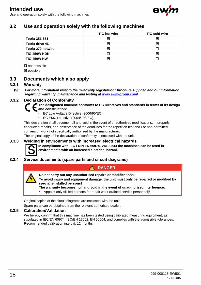
3.2 Use and operation solely with the following machines
TIG hot wire TIG cold wire
Tetrix 351-551
Tetrix drive 4L
Tetrix 270 hotwire
TIG 450W KDK
TIG 450W HW
not possible
possible
3.3 Documents which also apply 3.3.1 Warranty
For more information refer to the "Warranty registration" brochure supplied and our information
regarding warranty, maintenance and testing at www.ewm-group.com!
3.3.2 Declaration of Conformity
The designated machine conforms to EC Directives and standards in terms of its design
and construction:
• EC Low Voltage Directive (2006/95/EC),
• EC EMC Directive (2004/108/EC),
This declaration shall become null and void in the event of unauthorised modifications, improperly
conducted repairs, non-observance of the deadlines for the repetition test and / or non-permitted
conversion work not specifically authorised by the manufacturer.
The original copy of the declaration of conformity is enclosed with the unit.
3.3.3 Welding in environments with increased electrical hazards
In compliance with IEC / DIN EN 60974, VDE 0544 the machines can be used in
environments with an increased electrical hazard.
3.3.4 Service documents (spare parts and circuit diagrams)
DANGER
Do not carry out any unauthorised repairs or modifications!
To avoid injury and equipment damage, the unit must only be repaired or modified by
specialist, skilled persons!
The warranty becomes null and void in the event of unauthorised interference.
• Appoint only skilled persons for repair work (trained service personnel)!
Original copies of the circuit diagrams are enclosed with the unit.
Spare parts can be obtained from the relevant authorised dealer.
3.3.5 Calibration/Validation We hereby confirm that this machine has been tested using calibrated measuring equipment, as
stipulated in IEC/EN 60974, ISO/EN 17662, EN 50504, and complies with the admissible tolerances.
Recommended calibration interval: 12 months
Machine description – quick overview System overview
099-000115-EW501
17.06.2015 19
4 Machine description – quick overview 4.1 System overview
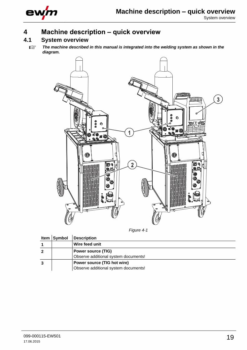
The machine described in this manual is integrated into the welding system as shown in the
diagram.
Figure 4-1
Item Symbol Description 0
1 Wire feed unit
2 Power source (TIG)
Observe additional system documents!
3 Power source (TIG hot wire)
Observe additional system documents!

Machine description – quick overview Tetrix 351 AC/DC AW
20 099-000115-EW501
17.06.2015
4.2 Tetrix 351 AC/DC AW
4.3 Front view
Figure 4-2

Machine description – quick overview Front view
099-000115-EW501
17.06.2015 21
Item Symbol Description 0
1 Lifting lug
2
Main switch, machine on/off
3 Machine control- See 4.8 Machine control – Operating elements chapter
4 Carrying handle
5
Automatic cut-out of coolant pump key button
press to reset a triggered fuse
6
Quick connect coupling (red)
coolant return
7
Quick connect coupling (blue)
coolant supply
8 Wheels, guide castors
9 Coolant tank
10 Coolant tank cap
11
Connection socket, 8-pole/12-pole (depending on variant)
8-pole: Control cable TIG up/down or potentiometer torch
12-pole: Control cable TIG up/down torch with LED display (option)
12
Connection socket, 5-pole
Standard TIG torch control lead
13
G¼” connecting nipple, “-” welding current
Shielding gas connection (with yellow insulating cap) for TIG welding torch
14
Connection socket, “-” welding current
TIG welding torch connection
15
Connection socket, “+” welding current
Connection for workpiece lead
16
Key switch for protection against unauthorised use
Position “1” > changes possible,
Position “0” > changes not possible.
- See 5.20 Protecting welding parameters from unauthorised access chapter
17
Connection socket, 19-pole
Remote control connection
18
Connection socket, “-” welding current
Electrode holder connection
19 Cooling air inlet
20
Operating state signal lamp
Lights up when the machine is ready for use.
21 Carrier plate for system components
only hot wire version

Machine description – quick overview Rear view
22 099-000115-EW501
17.06.2015
4.4 Rear view
Figure 4-3

Machine description – quick overview Rear view
099-000115-EW501
17.06.2015 23
Item Symbol Description 0
1 Intermediate hose package strain relief
2 Securing elements for shielding gas cylinder (strap/chain)
3 Mains connection cable
- See 5.5 Mains connection chapter
4
G¼” connecting nipple
Shielding gas connection on the pressure regulator.
5 Connector plug (TIG hot wire)
Welding current, minus potential
6
Connection socket for “+” welding current
Connection to TIG power source for hot wire application
7 Connection socket (TIG)
Welding current, minus potential
8
Quick connect coupling (red)
coolant return
9
Quick connect coupling (blue)
coolant supply
10 hotWire Control lead connection, hot wire power source
4-pole connection to the hot wire power source
11 X2 Connection socket (28-pole)
Control lead
12
Key button, automatic cutout
Wire feed motor supply voltage fuse
press to reset a triggered fuse
13 Mains connection, hot wire power source
Power supply for hot wire power source
14
Ignition type changeover switch- See 5.13.7 Arc ignition chapter
= Liftarc (contact ignition)
= HF ignition
15
19-pole mechanised welding interface (analogue)
- See 5.19.1 TIG interface for mechanised welding chapter
16
PC interface, serial (D-Sub connection socket, 9-pole)
17
7-pole connection socket (digital)
For connecting digital accessory components (documentation interface, robot interface
or remote control, etc.).
18 Cooling air outlet
19 Bracket for shielding gas cylinder
20 Wheels, fixed castors

Machine description – quick overview Tetrix 451, 551 AC/DC AW
24 099-000115-EW501
17.06.2015
4.5 Tetrix 451, 551 AC/DC AW
4.6 Front view
Figure 4-4

Machine description – quick overview Front view
099-000115-EW501
17.06.2015 25
Item Symbol Description 0
1 Lifting lug
2
Main switch, machine on/off
3 Machine control- See 4.8 Machine control – Operating elements chapter
4 Carrying handle
5
Automatic cut-out of coolant pump key button
press to reset a triggered fuse
6
Quick connect coupling (red)
coolant return
7
Quick connect coupling (blue)
coolant supply
8 Wheels, guide castors
9 Coolant tank
10 Coolant tank cap
11
Connection socket, 8-pole/12-pole (depending on variant)
8-pole: Control cable TIG up/down or potentiometer torch
12-pole: Control cable TIG up/down torch with LED display (option)
12
Connection socket, 5-pole
Standard TIG torch control lead
13
G¼“ connecting nipple, welding current "-" (with DC- polarity)
Shielding gas connection (with yellow insulating cap) for TIG welding torch
14
Connection socket, welding current “-” (with DC- polarity)
connection TIG welding torch
15
Connection socket, welding current “+” (with DC- polarity)
Connection for workpiece lead
16
Key switch for protection against unauthorised use
Position “1” > changes possible,
Position “0” > changes not possible.
- See 5.20 Protecting welding parameters from unauthorised access chapter
17
Connection socket, 19-pole
Remote control connection
18
Connection socket, welding current “-” (with DC- polarity)
connection for Electrode holder
19 Cooling air inlet
20
Operating state signal lamp
Lights up when the machine is ready for use.

Machine description – quick overview Rear view
26 099-000115-EW501
17.06.2015
4.7 Rear view
Figure 4-5

Machine description – quick overview Rear view
099-000115-EW501
17.06.2015 27
Item Symbol Description 0
1 Intermediate hose package strain relief
2 Securing elements for shielding gas cylinder (strap/chain)
3 Mains connection cable
- See 5.5 Mains connection chapter
4
G¼” connecting nipple
Shielding gas connection on the pressure regulator.
5 Connector plug (TIG hot wire)
Welding current, minus potential
6
Connection socket for “+” welding current
Connection to TIG power source for hot wire application
7 Connection socket (TIG)
Welding current, minus potential
8
Quick connect coupling (red)
coolant return
9
Quick connect coupling (blue)
coolant supply
10 hotWire Control lead connection, hot wire power source
4-pole connection to the hot wire power source
11 X2 Connection socket (28-pole)
Control lead
12
Key button, automatic cutout
Wire feed motor supply voltage fuse
press to reset a triggered fuse
13 Mains connection, hot wire power source
Power supply for hot wire power source
14
Ignition type changeover switch- See 5.13.7 Arc ignition chapter
= Liftarc (contact ignition)
= HF ignition
15
19-pole mechanised welding interface (analogue)
- See 5.19.1 TIG interface for mechanised welding chapter
16
PC interface, serial (D-Sub connection socket, 9-pole)
17
7-pole connection socket (digital)
For connecting digital accessory components (documentation interface, robot interface
or remote control, etc.).
18 Cooling air outlet
19 Bracket for shielding gas cylinder
20 Wheels, fixed castors

Machine description – quick overview Machine control – Operating elements
28 099-000115-EW501
17.06.2015
4.8 Machine control – Operating elements
Figure 4-6
Item Symbol Description 0
1
Polarity changeover (TIG manual) button Select material type (TIG
Synergic) key button
DC welding with positive polarity on the
electrode holder in relation to the
workpiece (pole reversing switch, MMA
only).
Chrome/nickel alloys / iron /
steel alloys
DC welding with negative polarity at the
torch (or electrode holder) with respect
to the workpiece.
Copper / copper alloys
(bronzes) / copper/zinc alloys
(brass)
AC welding with rectangular current
output wave form. Maximum power
loading and safe welding.
Aluminium/magnesium alloys
AC welding with trapezoidal current
output wave form. An all-rounder,
suitable for most applications.
Aluminium/silicon alloys
AC welding with sinusoidal current
output wave form. Low noise level. 99% aluminium
2
"Welding process" button
MMA welding, lights up in green / arcforce setting, lights up in red
TIG synergic welding (synergic parameter setting)
TIG manual welding (manual parameter setting)

Machine description – quick overview Machine control – Operating elements
099-000115-EW501
17.06.2015 29
Item Symbol Description 0
3
Tungsten electrode diameter / Ignition optimisation / Spherical cap formation button
1.0mm, 1.6mm, 2.0mm, 2.4mm, 3.2mm, 4.0mm or greater
Best ignition and stabilisation of the arc (DC, AC) and optimum spherical cup formation
in the tungsten electrode according to the electrode diameter being used. The
adjustable welding current is limited to the maximum permissible welding current of the
tungsten electrode.
4
Select seam type button
Fillet weld
Butt joint
Fillet weld - lap joint
Vertical-down
5
Operating mode / Power-saving mode button
spotArc / Spotmatic (spot time setting range)
Non-latched
Latched
Press for 3 s to put machine into power-saving mode. To reactivate, activate one of the
operating elements- See 5.22.3 Power-saving mode (Standby) chapter.
6
Pulsing push-button
TIG automated pulsing (frequency and balance)
Signal light lights up in green: Pulsing (thermal pulsing)/MMA pulse welding
Signal light lights up in red: kHz pulsing (metallurgical pulsing)
Special TIG AC
7
Synchronisation types key button (two-sided, simultaneous welding)
Synchronisation via mains voltage
Synchronisation via cable
8
Gas test/rinse hose package button
- See 5.8.2 Setting the shielding gas quantity chapter
9
Error/status indicators
Collective interference signal light
Water deficiency signal light (welding torch cooling)
Excess temperature signal light
safety sign signal light
10
Display switching button
Material thickness display
VOLT Welding voltage display
JOB JOB number display
PROG Program number display
11
Welding parameter setting rotary transducer
Setting of all parameters such as welding current, sheet metal thickness, gas pre-flow
time, etc.
12
Welding data display (3-digit)
Displays the welding parameters and the corresponding values
Machine description – quick overview Machine control – Operating elements
30 099-000115-EW501
17.06.2015
Item Symbol Description 0
13 Status displays
After each completed welding task, the last values used in the welding
process for the welding current and welding voltage are shown on the
displays, and the signal light will be on
Direct current welding
Alternating current welding
and simultaneously: Alternating current welding, AC special
14 Function sequence (see next chapter)
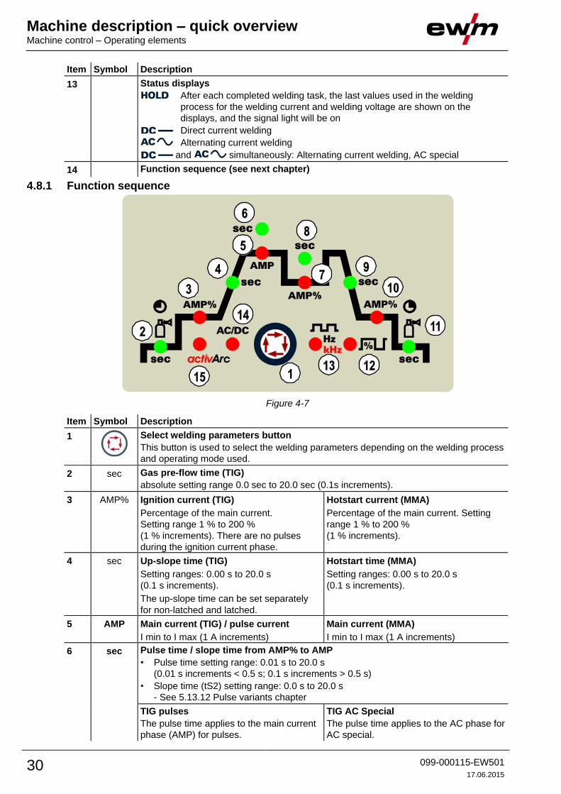
4.8.1 Function sequence
Figure 4-7
Item Symbol Description 0
1
Select welding parameters button
This button is used to select the welding parameters depending on the welding process
and operating mode used.
2 sec Gas pre-flow time (TIG)
absolute setting range 0.0 sec to 20.0 sec (0.1s increments).
3 AMP% Ignition current (TIG)
Percentage of the main current.
Setting range 1 % to 200 %
(1 % increments). There are no pulses
during the ignition current phase.
Hotstart current (MMA)
Percentage of the main current. Setting
range 1 % to 200 %
(1 % increments).
4 sec Up-slope time (TIG)
Setting ranges: 0.00 s to 20.0 s
(0.1 s increments).
The up-slope time can be set separately
for non-latched and latched.
Hotstart time (MMA)
Setting ranges: 0.00 s to 20.0 s
(0.1 s increments).
5 AMP Main current (TIG) / pulse current
I min to I max (1 A increments)
Main current (MMA)
I min to I max (1 A increments)
6 sec Pulse time / slope time from AMP% to AMP
• Pulse time setting range: 0.01 s to 20.0 s
(0.01 s increments < 0.5 s; 0.1 s increments > 0.5 s)
• Slope time (tS2) setting range: 0.0 s to 20.0 s
- See 5.13.12 Pulse variants chapter
TIG pulses
The pulse time applies to the main current
phase (AMP) for pulses.
TIG AC Special
The pulse time applies to the AC phase for
AC special.

Machine description – quick overview Machine control – Operating elements
099-000115-EW501
17.06.2015 31
Item Symbol Description 0
7 AMP% Secondary current (TIG) / pulse pause current
Setting range 1 % to 100 % (1 % increments). Percentage of the main current.
8 sec Pulse break time/slope time from AMP to AMP%
• Pulse break setting range: 0.01 sec to 20.0 sec
(0.01 sec increments < 0.5 sec; 0.1 sec increments > 0.5 sec)
• Slope time (tS1) setting range: 0.0 sec to 20.0 sec
"- See 5.13.12 Pulse variants chapter"
TIG pulses: The pulse break time applies to the secondary current phase (AMP%)
TIG AC Special: The pulse break time applies to the DC phase with AC special.
9 sec Down-slope time (TIG)
0.00 s to 20.0 s (0.1 s increments).
The down-slope time can be set separately for non-latched and latched.
10 AMP% End-crater current (TIG)
Setting range 1 % to 200 % (1 % increments). Percentage of the main current.
11 sec Gas post-flow time (TIG)
Setting ranges: 0.00 sec to 40.0 sec (0.1 sec increments).
12 Balance
TIG AC
Optimising cleaning effect and penetration characteristics. Max. setting range: -30% to
+30% (increments of 1%). Depending on the factory settings, the setting range can be
smaller as well.
TIG DC kHz-pulsing (metallurgical pulsing)
Setting range: 1% to +99% (increments of 1%)
MMA pulse welding
Setting range: 1% to +99% (increments of 1%)
13
Frequency
TIG AC
Constriction and stabilisation of the arc:
The cleaning effect increases with a higher frequency. Especially thin metal sheets
(welding with low current), anodised aluminium sheets or very impure weld metals can
be welded and cleaned immaculately with higher frequency.
50 Hz to 200 Hz (increments of 1 Hz).
TIG DC kHz-pulsing (metallurgical pulsing)
Setting range: 0.05 kHz to 15 kHz
MMA pulse welding
Setting range: 0.2 Hz to 500 Hz
14 AC/DC Welding current polarity, MMA
- See 5.14.3 Welding current polarity reversal (polarity reversal) chapter
15 activArc TIG welding process
• Switch activArc on or off
• Correct the activArc characteristic (setting range: 0 to 100)

Design and function General
32 099-000115-EW501
17.06.2015
5 Design and function 5.1 General
WARNING
Risk of injury from electric shock!
Contact with live parts, e.g. welding current sockets, is potentially fatal!
• Follow safety instructions on the opening pages of the operating instructions.
• Commissioning may only be carried out by persons who have the relevant expertise of
working with arc welding machines!
• Connection and welding leads (e.g. electrode holder, welding torch, workpiece lead,
interfaces) may only be connected when the machine is switched off!
CAUTION
Insulate the arc welder from welding voltage!
Not all active parts of the welding current circuit can be shielded from direct contact. To
avoid any associated risks it is vital for the welder to adhere to the relevant safety
regulations. Even low voltages can cause a shock and lead to accidents.
• Wear dry and undamaged protective clothing (shoes with rubber soles/welder's gloves
made from leather without any studs or braces)!
• Avoid direct contact with non-insulated connection sockets or connectors!
• Always place torches and electrode holders on an insulated surface!
Risk of burns on the welding current connection!
If the welding current connections are not locked, connections and leads heat up and
can cause burns, if touched!
• Check the welding current connections every day and lock by turning in clockwise direction,
if necessary.
Risk of injury due to moving parts!
The wire feeders are equipped with moving parts, which can trap hands, hair, clothing
or tools and thus injure persons!
• Do not reach into rotating or moving parts or drive components!
• Keep casing covers or protective caps closed during operation!
Risk of injury due to welding wire escaping in an unpredictable manner!
Welding wire can be conveyed at very high speeds and, if conveyed incorrectly, may
escape in an uncontrolled manner and injure persons!
• Before mains connection, set up the complete wire guide system from the wire spool to the
welding torch!
• Remove the pressure rollers from the wire feeder if no welding torch is fitted!
• Check wire guide at regular intervals!
• Keep all casing covers or protective caps closed during operation!
Risk from electrical current!
If welding is carried out alternately using different methods and if a welding torch and
an electrode holder remain connected to the machine, the open-circuit/welding voltage
is applied simultaneously on all cables.
• The torch and the electrode holder should therefore always be placed on an insulated
surface before starting work and during breaks.
Design and function Machine cooling
099-000115-EW501
17.06.2015 33
CAUTION
Damage due to incorrect connection!
Accessory components and the power source itself can be damaged by incorrect
connection!
• Only insert and lock accessory components into the relevant connection socket when the
machine is switched off.
• Comprehensive descriptions can be found in the operating instructions for the relevant
accessory components.
• Accessory components are detected automatically after the power source is switched on.
Using protective dust caps!
Protective dust caps protect the connection sockets and therefore the machine against
dirt and damage.
• The protective dust cap must be fitted if there is no accessory component being operated
on that connection.
• The cap must be replaced if faulty or if lost!
Observe documentation of other system components when connecting!
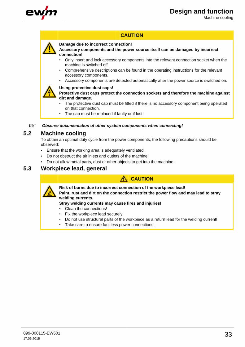
5.2 Machine cooling To obtain an optimal duty cycle from the power components, the following precautions should be
observed:
• Ensure that the working area is adequately ventilated.
• Do not obstruct the air inlets and outlets of the machine.
• Do not allow metal parts, dust or other objects to get into the machine.
5.3 Workpiece lead, general
CAUTION
Risk of burns due to incorrect connection of the workpiece lead!
Paint, rust and dirt on the connection restrict the power flow and may lead to stray
welding currents.
Stray welding currents may cause fires and injuries!
• Clean the connections!
• Fix the workpiece lead securely!
• Do not use structural parts of the workpiece as a return lead for the welding current!
• Take care to ensure faultless power connections!

Design and function Notes on the installation of welding current leads
34 099-000115-EW501
17.06.2015
5.4 Notes on the installation of welding current leads
Incorrectly installed welding current leads can cause faults in the arc (flickering).
Lay the workpiece lead and hose package of power sources without HF igniter (MIG/MAG) for as
long and as close as possible in parallel.
Lay the workpiece lead and hose package of power sources with HF igniter (TIG) for as long as
possible in parallel with a distance of 20 cm to avoid HF sparkover.
Always keep a distance of at least 20 cm to leads of other power sources to avoid interferences
Always keep leads as short as possible! For optimum welding results max. 30 m (welding lead +
intermediate hose package + torch lead).
Figure 5-1
Design and function Notes on the installation of welding current leads
099-000115-EW501
17.06.2015 35
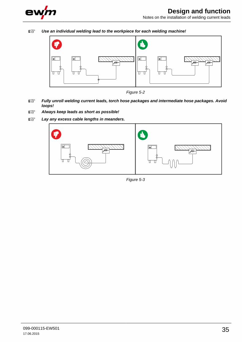
Use an individual welding lead to the workpiece for each welding machine!
Figure 5-2
Fully unroll welding current leads, torch hose packages and intermediate hose packages. Avoid
loops!
Always keep leads as short as possible!
Lay any excess cable lengths in meanders.
Figure 5-3
Design and function Mains connection
36 099-000115-EW501
17.06.2015
5.5 Mains connection
DANGER
Hazard caused by improper mains connection!
An improper mains connection can cause injuries or damage property!
• Only use machine with a plug socket that has a correctly fitted protective conductor.
• If a mains plug must be fitted, this may only be carried out by an electrician in accordance
with the relevant national provisions or regulations!
• Mains plug, socket and lead must be checked regularly by an electrician!
• When operating the generator always ensure it is earthed as stated in the operating
instructions. The resulting network has to be suitable for operating devices according to
protection class 1.
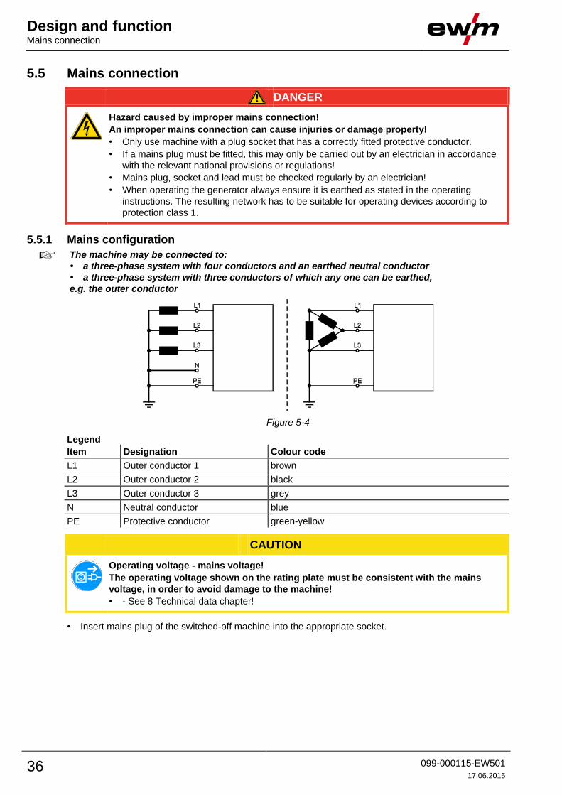
5.5.1 Mains configuration
The machine may be connected to:
• a three-phase system with four conductors and an earthed neutral conductor
• a three-phase system with three conductors of which any one can be earthed,
e.g. the outer conductor
Figure 5-4
Legend
Item Designation Colour code
L1 Outer conductor 1 brown
L2 Outer conductor 2 black
L3 Outer conductor 3 grey
N Neutral conductor blue
PE Protective conductor green-yellow
CAUTION
Operating voltage - mains voltage!
The operating voltage shown on the rating plate must be consistent with the mains
voltage, in order to avoid damage to the machine!
• - See 8 Technical data chapter!
• Insert mains plug of the switched-off machine into the appropriate socket.

Design and function Welding torch cooling system
099-000115-EW501
17.06.2015 37
5.6 Welding torch cooling system
CAUTION
Coolant mixtures!
Mixtures with other liquids or the use of unsuitable coolants result in material damage
and renders the manufacturer's warranty void!
• Only use the coolant described in this manual (overview of coolants).
• Do not mix different coolants.
• When changing the coolant, the entire volume of liquid must be changed.
Insufficient frost protection in the welding torch coolant!
Depending on the ambient conditions, different liquids are used for cooling the welding
torch - See 5.6.1 List of coolants chapter.
Coolants with frost protection (KF 37E or KF 23E) must be checked regularly to ensure
that the frost protection is adequate to prevent damage to the machine or the accessory
components.
• The coolant must be checked for adequate frost protection with the TYP 1 frost protection
tester .
• Replace coolant as necessary if frost protection is inadequate!
The disposal of coolant must be carried out according to official regulations and observing the
relevant safety data sheets (German waste code number: 70104)!
Coolant must not be disposed of together with household waste.
Coolant must not be discharged into the sewerage system.
Recommended cleaning agent: water, if necessary with cleaning agent added.
5.6.1 List of coolants The following coolants may be used - See 9 Accessories chapter:
Coolant Temperature range
KF 23E (Standard) -10 °C to +40 °C
KF 37E -20 °C to +10 °C
5.6.2 Maximal hose package length Pump 3.5 bar Pump 4.5 bar
Machines with or without separate wire feeder 30 m 60 m
Compact machines with additional intermediate
drive (example. miniDrive) 20 m 30 m
Machines with separate wire feeder and additional
intermediate drive (example: miniDrive) 20 m 60 m
Data as a rule refer to the entire hose package length
including welding torch. The pump output is shown on the type plate (parameter: Pmax).
Pump 3.5 bar: Pmax = 0.35 MPa (3.5 bar)
Pump 4.5 bar: Pmax = 0.45 MPa (4.5 bar)

Design and function Welding torch cooling system
38 099-000115-EW501
17.06.2015
5.6.3 Adding coolant The unit is supplied ex works with a minimum level of coolant.
Figure 5-5
Item Symbol Description 0
1 Coolant tank cap
2 Coolant filter sieve
3 Coolant tank
4 "Min" mark
Minimum coolant level
• Unscrew and remove the coolant tank sealing cover.
• Check filter sieve insert for dirt, clean if necessary and reinsert into position.
• Top up coolant to the filter sieve insert, close sealing cover again.
After the initial filling, wait for at least one minute when the machine is switched on so that the
hose package is filled with coolant completely and without bubbles.
With frequent changes of torch and during the initial filling process, the cooling unit tank should
be topped up as necessary.
The level of coolant must never fall below the “min” mark.
If there is less coolant in the coolant tank than the minimum required you may need to vent the
coolant circuit. In this case the welding machine will automatically shut down the coolant pump
and signal an error, "- See 7 Rectifying faults chapter".

Design and function Shielding gas supply (shielding gas cylinder for welding machine)
099-000115-EW501
17.06.2015 39
5.7 Shielding gas supply (shielding gas cylinder for welding machine)
WARNING
Risk of injury due to improper handling of shielding gas cylinders!
Improper handling and insufficient securing of shielding gas cylinders
can cause serious injuries!
• Secure shielding gas cylinders using the standard fastening elements on
the unit (chain/belt)!
• The fastening elements must tightly enclose the shielding gas cylinder!
• Attach the fastening elements within the upper half of the shielding gas
cylinder!
• Do not attach any element to the shielding gas cylinder valve!
• Observe the instructions from the gas manufacturer and any relevant
regulations concerning the use of compressed air!
• Avoid heating the shielding gas cylinder!
• When using shielding gas cylinders smaller than 50 litres, the ON
HOLDER GAS BOTTLE option must be retrofitted
CAUTION
Faults in the shielding gas supply.
An unhindered shielding gas supply from the shielding gas cylinder to the welding
torch is a fundamental requirement for optimum welding results. In addition, a blocked
shielding gas supply may result in the welding torch being destroyed.
• Always re-fit the yellow protective cap when not using the shielding gas connection.
• All shielding gas connections must be gas tight.
Before connecting the pressure regulator to the gas cylinder, open the cylinder valve briefly to
expel any dirt.
5.7.1 Connection
Figure 5-6
Item Symbol Description 0
1 Pressure regulator
2 Shielding gas cylinder
3 Output side of the pressure regulator
4 Cylinder valve
• Place the shielding gas cylinder into the relevant cylinder bracket.
• Secure the shielding gas cylinder using a securing chain.
• Tighten the pressure regulator screw connection on the gas bottle valve to be gas-tight.

Design and function TIG welding
40 099-000115-EW501
17.06.2015
5.8 TIG welding • Fasten the gas hose to the shielding gas connecting nipple at the back of the machine using the crown
nut.
5.8.1 TIG cold or hot wire welding • Screw the gas hose connection nipple (intermediate hose package) onto the output side of the
pressure regulator.
5.8.2 Setting the shielding gas quantity
Rule of thumb for the gas flow rate:
Diameter of gas nozzle in mm corresponds to gas flow in l/min.
Example: 7mm gas nozzle corresponds to 7l/min gas flow.
Incorrect shielding gas setting!
• If the shielding gas setting is too low or too high, this can introduce air to the weld pool and
may cause pores to form.
• Adjust the shielding gas quantity to suit the welding task!
5.8.3 Gas test Operating
element
Action Result
1 x Select gas test
"Gas pre-flow time (TIG)" signal light is on. Shielding gas flows for
approx. 20 seconds. The gas test can be ended immediately by
pressing it once more.
5.8.4 “Purge hose package” function Operating
element
Action Result
5 s Select hose package rinsing
"Gas pre-flow time (TIG)" signal light flashes.
The function is ended by pressing the button again.
If the "Rinse hose package" function is not ended by pressing the "Gas and current parameters"
button again, shielding gas will flow until the gas cylinder is empty!
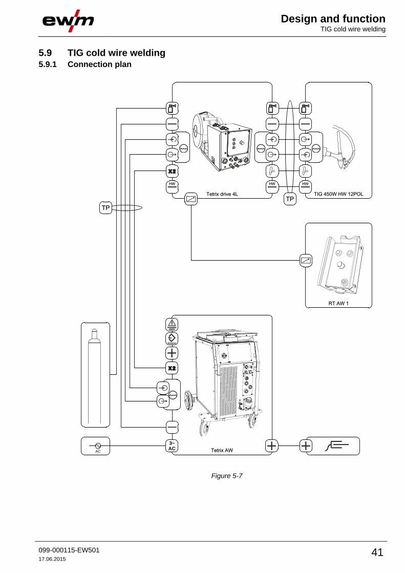
Design and function TIG cold wire welding
099-000115-EW501
17.06.2015 41
5.9 TIG cold wire welding 5.9.1 Connection plan
Tetrix AW
3~AC
Tetrix drive 4L TIG 450W HW 12POL
AC
HW
X2
X2
hotwire
HW HW
TP
TP
RT AW 1
Figure 5-7

Design and function TIG cold wire welding
42 099-000115-EW501
17.06.2015
5.9.2 Legend
Shielding gas
Welding current(minus potential)
Coolant input (marked in colour)
Coolant output (marked in colour)
X2
Control lead (28-pole)
TP
Hose package (TP = tube package)
HW
Welding current (minus potential, TIG hot wire)
Welding current (plus potential, workpiece)
hotwire
Control lead, hot wire (signal input, 4-pole)
3~AC
Connection, supply voltage (3-phase)
Supply voltage, hot wire power source
hotwire
Control lead, hot wire (signal output, 4-pole)
Control lead, welding torch (12-pole)
Remote control connection
5.9.3 Installation
CAUTION
Installation site!
The machine must not be operated in the open air and must only be set up and
operated on a suitable, stable and level base!
• The operator must ensure that the ground is non-slip and level, and provide sufficient
lighting for the place of work.
• Safe operation of the machine must be guaranteed at all times.
In a TIG cold wire welding system the wire feed unit is placed onto the casing cover of the TIG
power source.
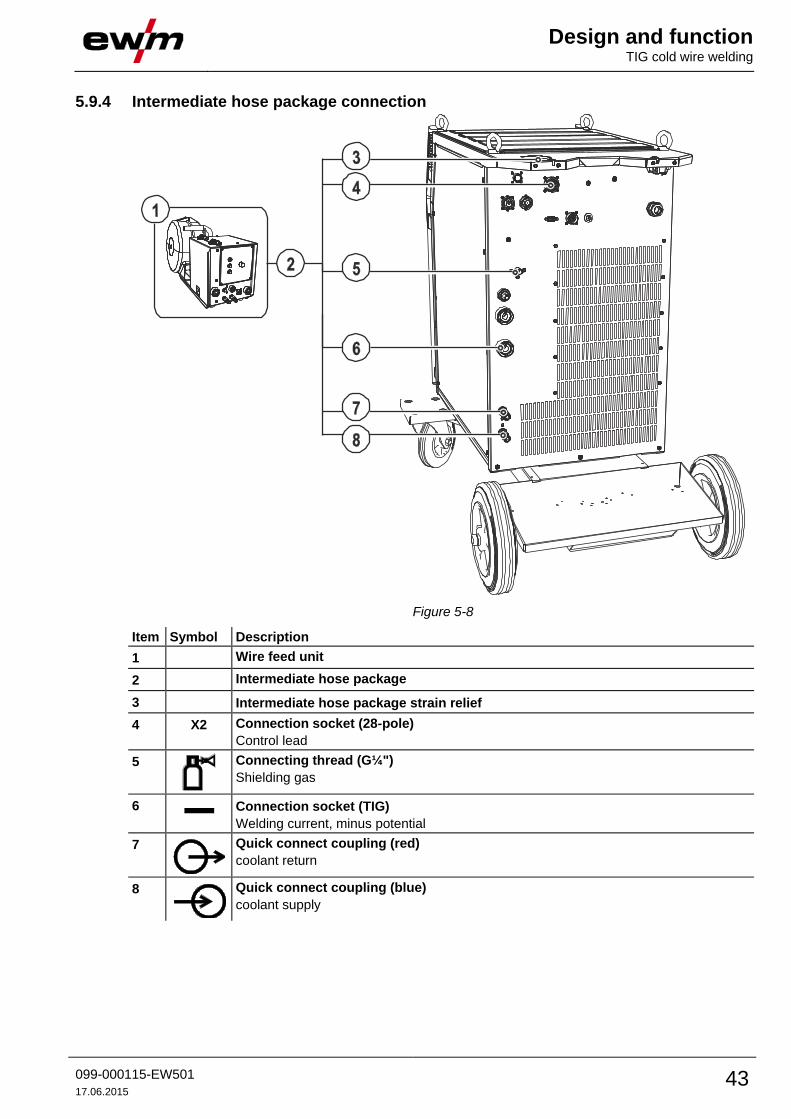
Design and function TIG cold wire welding
099-000115-EW501
17.06.2015 43
5.9.4 Intermediate hose package connection
Figure 5-8
Item Symbol Description 0
1 Wire feed unit
2 Intermediate hose package
3 Intermediate hose package strain relief
4 X2 Connection socket (28-pole)
Control lead
5
Connecting thread (G¼")
Shielding gas
6 Connection socket (TIG)
Welding current, minus potential
7
Quick connect coupling (red)
coolant return
8
Quick connect coupling (blue)
coolant supply

Design and function TIG cold wire welding
44 099-000115-EW501
17.06.2015
• Insert the end of the hose package through the strain relief of the hose package and lock by turning to
the right.
• Push the cable plug for the welding current (TIG) onto the connection socket (TIG) and lock by turning
to the right.
• Insert cable plug on the control lead into the connection socket (28-pole) and secure with crown nut
(the plug can only be inserted into the connection socket in one position).
• Lock connecting nipples of the cooling water tubes into the corresponding quick connect couplings:
Return line red to quick connect coupling, red (coolant return) and
supply line blue to quick connect coupling, blue (coolant supply).
• Screw the crown nut on the shielding gas lead gastight to the connecting thread (G¼").

Design and function TIG hot wire welding
099-000115-EW501
17.06.2015 45
5.10 TIG hot wire welding 5.10.1 Connection plan
Tetrix AW
3~AC
Tetrix Hotwire
Tetrix drive 4L TIG 450W HW 12POL
AC
HW
X2
X2
hotwire
hotwire
HW
HW HW
3~AC
TP
TP
RT AW 1
Figure 5-9

Design and function TIG hot wire welding
46 099-000115-EW501
17.06.2015
5.10.1.1 Legend
Shielding gas
Welding current(minus potential)
Coolant input (marked in colour)
Coolant output (marked in colour)
X2
Control lead (28-pole)
TP
Hose package (TP = tube package)
HW
Welding current (minus potential, TIG hot wire)
Welding current (plus potential, workpiece)
hotwire
Control lead, hot wire (signal input, 4-pole)
3~AC
Connection, supply voltage (3-phase)
Supply voltage, hot wire power source
hotwire
Control lead, hot wire (signal output, 4-pole)
Control lead, welding torch (12-pole)
Remote control connection
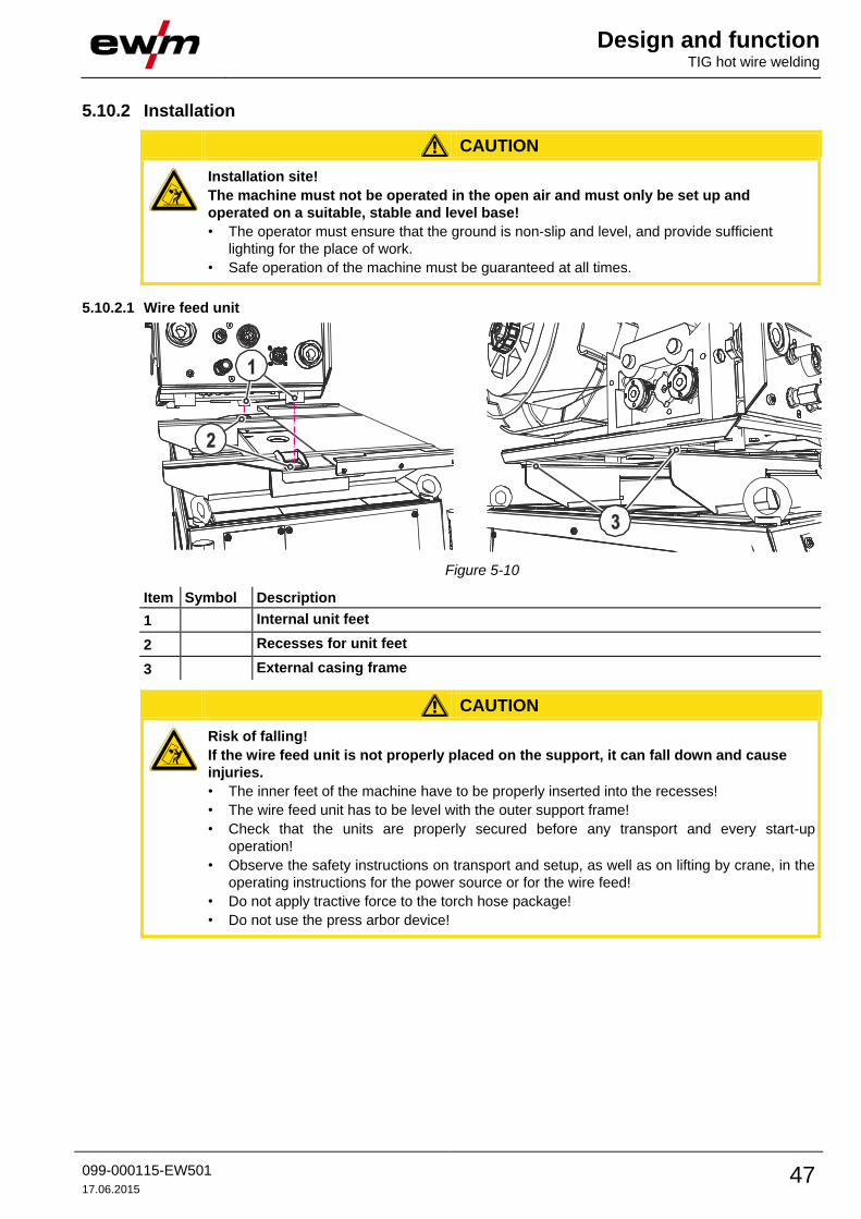
Design and function TIG hot wire welding
099-000115-EW501
17.06.2015 47
5.10.2 Installation
CAUTION
Installation site!
The machine must not be operated in the open air and must only be set up and
operated on a suitable, stable and level base!
• The operator must ensure that the ground is non-slip and level, and provide sufficient
lighting for the place of work.
• Safe operation of the machine must be guaranteed at all times.
5.10.2.1 Wire feed unit
Figure 5-10
Item Symbol Description 0
1 Internal unit feet
2 Recesses for unit feet
3 External casing frame
CAUTION
Risk of falling!
If the wire feed unit is not properly placed on the support, it can fall down and cause
injuries.
• The inner feet of the machine have to be properly inserted into the recesses!
• The wire feed unit has to be level with the outer support frame!
• Check that the units are properly secured before any transport and every start-up
operation!
• Observe the safety instructions on transport and setup, as well as on lifting by crane, in the
operating instructions for the power source or for the wire feed!
• Do not apply tractive force to the torch hose package!
• Do not use the press arbor device!
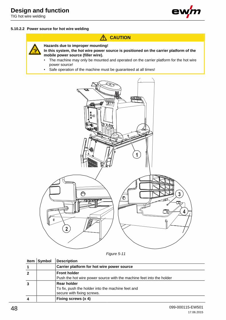
Design and function TIG hot wire welding
48 099-000115-EW501
17.06.2015
5.10.2.2 Power source for hot wire welding
CAUTION
Hazards due to improper mounting!
In this system, the hot wire power source is positioned on the carrier platform of the
mobile power source (filler wire).
• The machine may only be mounted and operated on the carrier platform for the hot wire
power source!
• Safe operation of the machine must be guaranteed at all times!
Figure 5-11
Item Symbol Description 0
1 Carrier platform for hot wire power source
2 Front holder
Push the hot wire power source with the machine feet into the holder
3 Rear holder
To fix, push the holder into the machine feet and
secure with fixing screws.
4 Fixing screws (x 4)
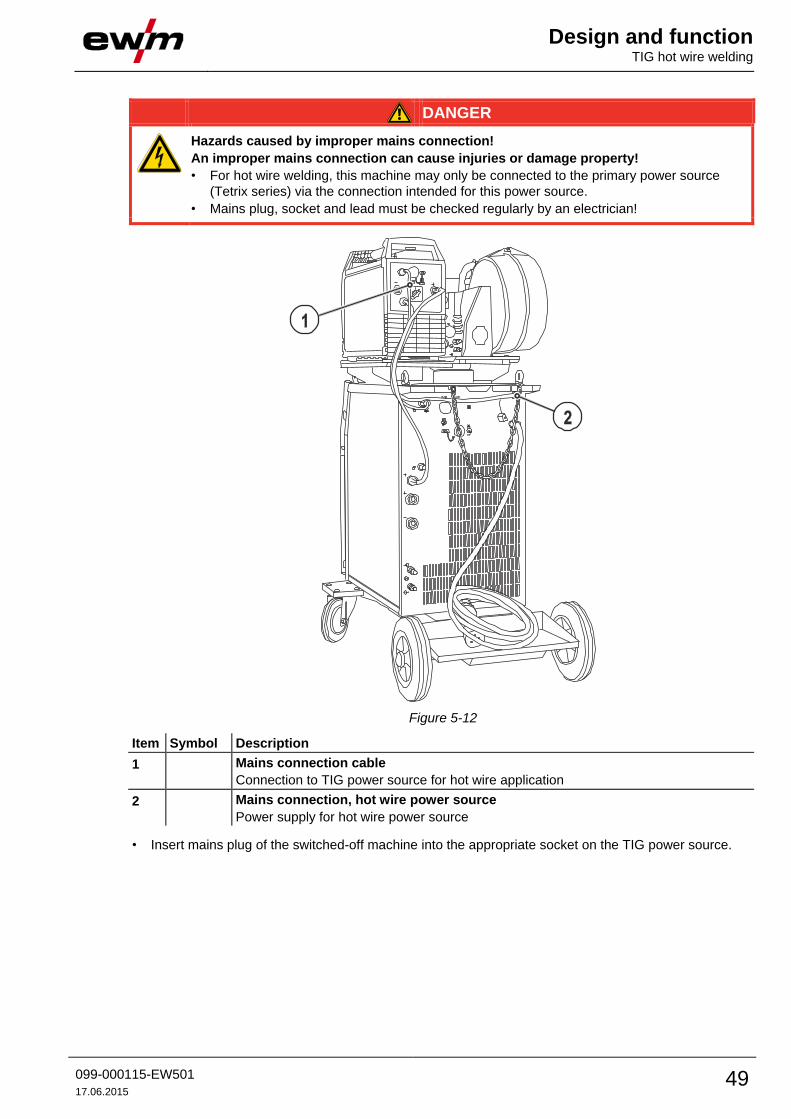
Design and function TIG hot wire welding
099-000115-EW501
17.06.2015 49
DANGER
Hazards caused by improper mains connection!
An improper mains connection can cause injuries or damage property!
• For hot wire welding, this machine may only be connected to the primary power source
(Tetrix series) via the connection intended for this power source.
• Mains plug, socket and lead must be checked regularly by an electrician!
Figure 5-12
Item Symbol Description 0
1 Mains connection cable
Connection to TIG power source for hot wire application
2 Mains connection, hot wire power source
Power supply for hot wire power source
• Insert mains plug of the switched-off machine into the appropriate socket on the TIG power source.
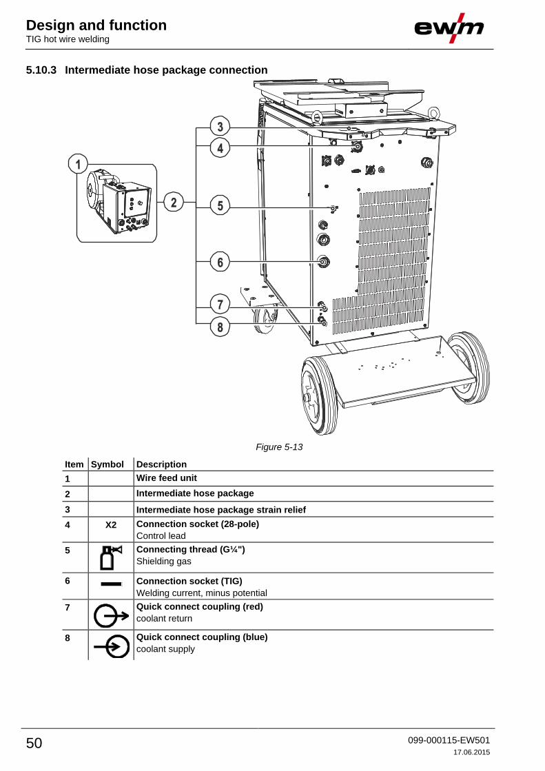
Design and function TIG hot wire welding
50 099-000115-EW501
17.06.2015
5.10.3 Intermediate hose package connection
Figure 5-13
Item Symbol Description 0
1 Wire feed unit
2 Intermediate hose package
3 Intermediate hose package strain relief
4 X2 Connection socket (28-pole)
Control lead
5
Connecting thread (G¼")
Shielding gas
6 Connection socket (TIG)
Welding current, minus potential
7
Quick connect coupling (red)
coolant return
8
Quick connect coupling (blue)
coolant supply

Design and function TIG hot wire welding
099-000115-EW501
17.06.2015 51
• Insert the end of the hose package through the strain relief of the hose package and lock by turning to
the right.
• Push the cable plug for the welding current (TIG) onto the connection socket (TIG) and lock by turning
to the right.
• Insert cable plug on the control lead into the connection socket (28-pole) and secure with crown nut
(the plug can only be inserted into the connection socket in one position).
• Lock connecting nipples of the cooling water tubes into the corresponding quick connect couplings:
Return line red to quick connect coupling, red (coolant return) and
supply line blue to quick connect coupling, blue (coolant supply).
• Screw the crown nut on the shielding gas lead gastight to the connecting thread (G¼").
The current lead for preheating (35 mm2) is only connected to the hot wire power source when
such a power source is used.
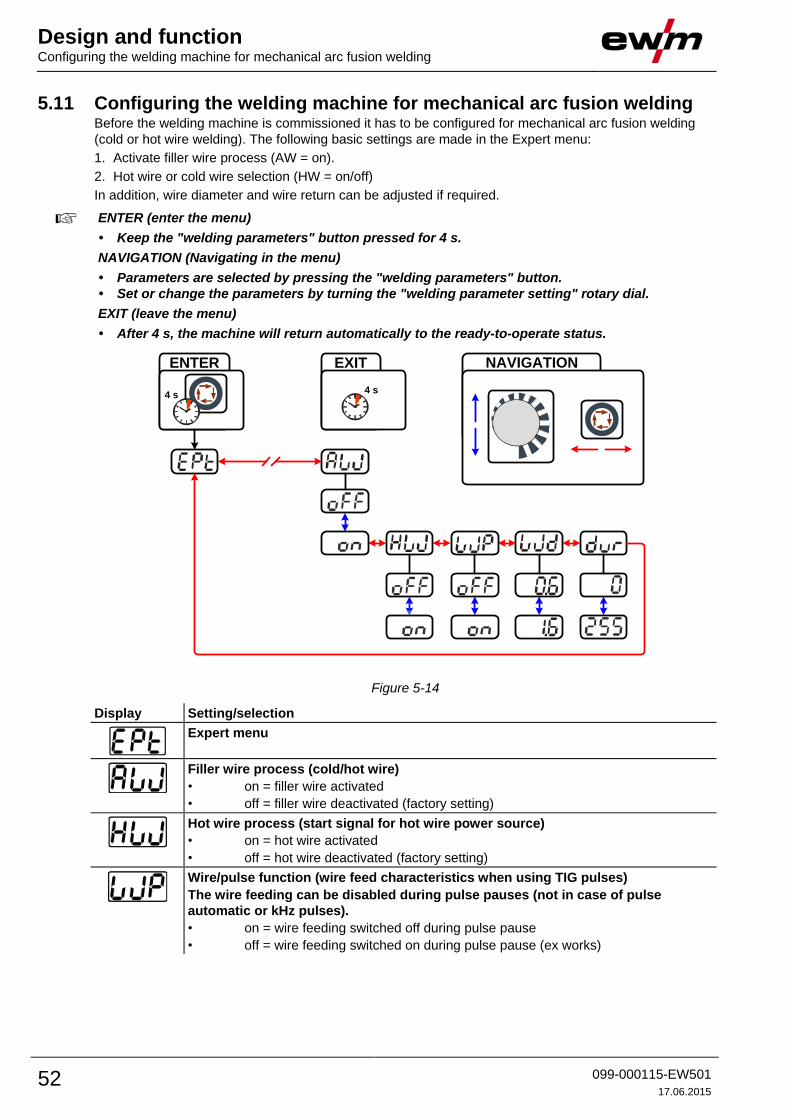
Design and function Configuring the welding machine for mechanical arc fusion welding
52 099-000115-EW501
17.06.2015
5.11 Configuring the welding machine for mechanical arc fusion welding Before the welding machine is commissioned it has to be configured for mechanical arc fusion welding
(cold or hot wire welding). The following basic settings are made in the Expert menu:
1. Activate filler wire process (AW = on).
2. Hot wire or cold wire selection (HW = on/off)
In addition, wire diameter and wire return can be adjusted if required.
ENTER (enter the menu)
• Keep the "welding parameters" button pressed for 4 s.
NAVIGATION (Navigating in the menu)
• Parameters are selected by pressing the "welding parameters" button.
• Set or change the parameters by turning the "welding parameter setting" rotary dial.
EXIT (leave the menu)
• After 4 s, the machine will return automatically to the ready-to-operate status.
ENTER EXIT
4 s4 s
NAVIGATION
Figure 5-14
Display Setting/selection
Expert menu
Filler wire process (cold/hot wire)
• on = filler wire activated
• off = filler wire deactivated (factory setting)
Hot wire process (start signal for hot wire power source)
• on = hot wire activated
• off = hot wire deactivated (factory setting)
Wire/pulse function (wire feed characteristics when using TIG pulses)
The wire feeding can be disabled during pulse pauses (not in case of pulse
automatic or kHz pulses).
• on = wire feeding switched off during pulse pause
• off = wire feeding switched on during pulse pause (ex works)

Design and function Configuring the welding machine for mechanical arc fusion welding
099-000115-EW501
17.06.2015 53
Display Setting/selection
Filler wire diameter (manual setting)
Setting of the wire diameter from 0.6 mm to 1.6 mm.
The character "d" preceding the wire diameter on the display (d0.8) indicates a pre-
programmed characteristics (operating mode KORREKTUR).
If there is no characteristics for the selected wire diameter, the parameters have to be set
manually (operating mode MANUELL).
For information on how to select the operating mode- See 5.11.2 Select wire speed
operating mode (KORREKTUR / MANUELL) chapter.
Wire return
• Increase value = more wire return
• Reduce value = less wire return
Parameter can also be set after connecting a TIG cold wire feed unit. Setting: 0 to 255
(factory setting 50).
Please note the relevant documentation of the accessory components.
5.11.1 Selecting a welding task by means of the JOB list • Select material, tungsten electrode and seam position on the welding machine controls.
The welding task number (JOB number) results from the chosen basic parameters. If no wire
speed is assigned to this JOB-number (- See 10.1 JOB-List chapter), wire feeding will not take
place. In order to carry out the chosen welding task, the wire feed unit must be switched to the
MANUELL operating mode - See 5.11.2 Select wire speed operating mode (KORREKTUR /
MANUELL) chapter.
5.11.2 Select wire speed operating mode (KORREKTUR / MANUELL) The wire speed can be set in two different operating modes:
MANUAL: The wire speed can be selected on the wire feed unit as an absolute value across the
entire setting range.
CORRETION: The wire speed is approximately specified by the welding machine control and can be
corrected as a percentage on the wire feed unit
In the wire feed unit underneath the cap is a switch for selecting the operating mode.
5.11.3 Setting the welding current and wire speed Operating
element
Action Result
Set welding current on the welding machine
Set wire speed
MANUAL operating mode (outer scale):
The wire speed can be selected on the wire feed unit as an absolute
value across the entire setting range.
CORRECTION operating mode (inner scale):
The wire speed is specified largely by the welding machine control and
can be corrected as a percentage on the wire feed unit

Design and function Configuring the welding machine for mechanical arc fusion welding
54 099-000115-EW501
17.06.2015
5.11.4 Function sequences/operating modes
The welding current operating mode must be set to latched on the welding machine. The welding
current is infinitely adjustable by means of torch triggers 3 and 4 (BRT 3 and BRT 4). Torch
trigger 2 (BRT 2) switches the welding current on or off.
Torch trigger 1 (BRT 1) switches the wire feed on or off. The operator can choose between three
operating modes (see following function sequences).
Figure 5-15
5.11.4.1 Explanation of symbols
Symbol Meaning
Press torch trigger
Release torch trigger
Tap torch trigger (press briefly and release)
Shielding gas flowing
I Welding output
Gas pre-flows
Gas post-flows
Non-latched
Special, non-latched
Latched
Special, latched
t Time
PSTART Ignition program
PA Main program
PB Reduced main program
PEND End program
tS1 Slope duration from PSTART to PA
Wire feed
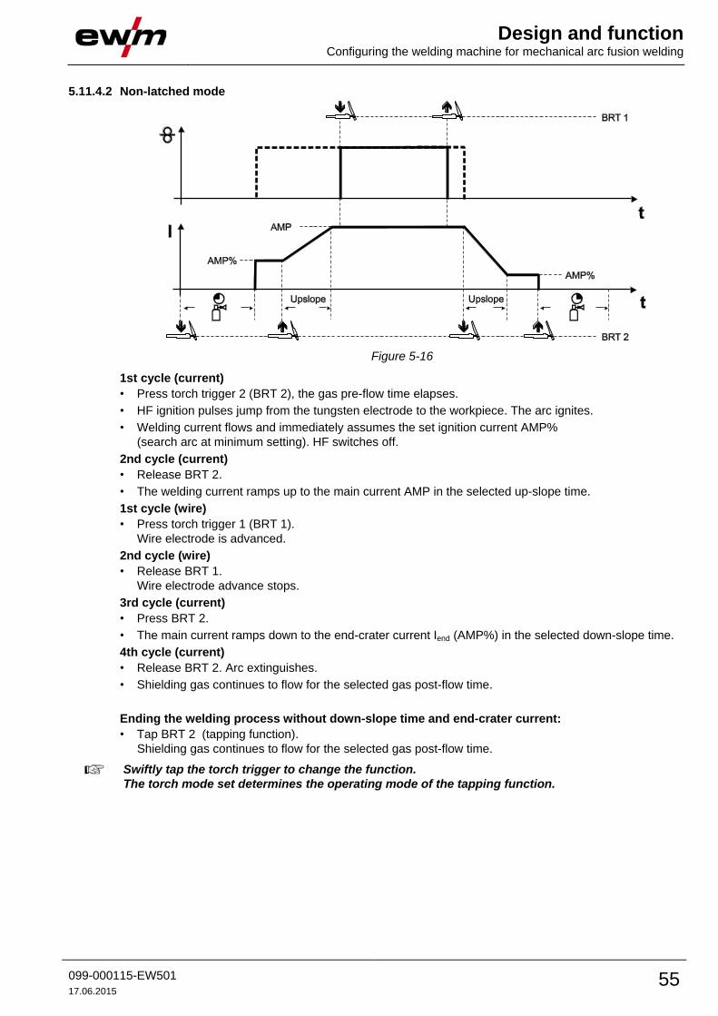
Design and function Configuring the welding machine for mechanical arc fusion welding
099-000115-EW501
17.06.2015 55
5.11.4.2 Non-latched mode
Figure 5-16
1st cycle (current)
• Press torch trigger 2 (BRT 2), the gas pre-flow time elapses.
• HF ignition pulses jump from the tungsten electrode to the workpiece. The arc ignites.
• Welding current flows and immediately assumes the set ignition current AMP%
(search arc at minimum setting). HF switches off.
2nd cycle (current)
• Release BRT 2.
• The welding current ramps up to the main current AMP in the selected up-slope time.
1st cycle (wire)
• Press torch trigger 1 (BRT 1).
Wire electrode is advanced.
2nd cycle (wire)
• Release BRT 1.
Wire electrode advance stops.
3rd cycle (current)
• Press BRT 2.
• The main current ramps down to the end-crater current Iend (AMP%) in the selected down-slope time.
4th cycle (current)
• Release BRT 2. Arc extinguishes.
• Shielding gas continues to flow for the selected gas post-flow time.
Ending the welding process without down-slope time and end-crater current:
• Tap BRT 2 (tapping function).
Shielding gas continues to flow for the selected gas post-flow time.
Swiftly tap the torch trigger to change the function.
The torch mode set determines the operating mode of the tapping function.
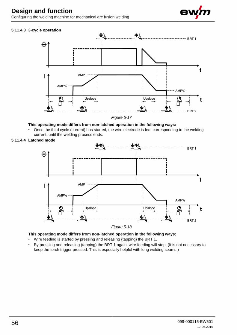
Design and function Configuring the welding machine for mechanical arc fusion welding
56 099-000115-EW501
17.06.2015
5.11.4.3 3-cycle operation
Figure 5-17
This operating mode differs from non-latched operation in the following ways:
• Once the third cycle (current) has started, the wire electrode is fed, corresponding to the welding
current, until the welding process ends.
5.11.4.4 Latched mode
Figure 5-18
This operating mode differs from non-latched operation in the following ways:
• Wire feeding is started by pressing and releasing (tapping) the BRT 1.
• By pressing and releasing (tapping) the BRT 1 again, wire feeding will stop. (It is not necessary to
keep the torch trigger pressed. This is especially helpful with long welding seams.)

Design and function TIG welding
099-000115-EW501
17.06.2015 57
5.12 TIG welding 5.12.1 Welding torch and workpiece line connection
CAUTION
Equipment damage due to improperly connected coolant pipes!
If the coolant pipes are not properly connected or a gas-cooled welding torch is used,
the coolant circuit is interrupted and equipment damage can occur.
• Connect all coolant pipes correctly!
• Completely unroll the hose package and the torch hose package!
• Observe maximal hose package length - See 5.6 Welding torch cooling system chapter.
• When using a gas-cooled welding torch, use a hose bridge to establish the coolant circuit -
See 9 Accessories chapter.
Prepare welding torch according to the welding task in hand (see operating instructions for the
torch).
Figure 5-19
Item Symbol Description 0
1
Welding torch
2 Welding torch hose package
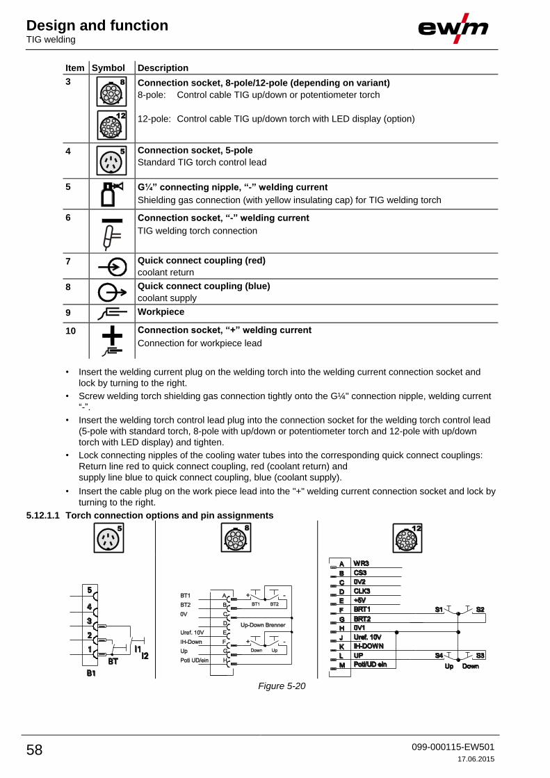
Design and function TIG welding
58 099-000115-EW501
17.06.2015
Item Symbol Description 0
3
Connection socket, 8-pole/12-pole (depending on variant)
8-pole: Control cable TIG up/down or potentiometer torch
12-pole: Control cable TIG up/down torch with LED display (option)
4
Connection socket, 5-pole
Standard TIG torch control lead
5
G¼” connecting nipple, “-” welding current
Shielding gas connection (with yellow insulating cap) for TIG welding torch
6
Connection socket, “-” welding current
TIG welding torch connection
7
Quick connect coupling (red)
coolant return
8
Quick connect coupling (blue)
coolant supply
9
Workpiece
10
Connection socket, “+” welding current
Connection for workpiece lead
• Insert the welding current plug on the welding torch into the welding current connection socket and
lock by turning to the right.
• Screw welding torch shielding gas connection tightly onto the G¼" connection nipple, welding current
“-”.
• Insert the welding torch control lead plug into the connection socket for the welding torch control lead
(5-pole with standard torch, 8-pole with up/down or potentiometer torch and 12-pole with up/down
torch with LED display) and tighten.
• Lock connecting nipples of the cooling water tubes into the corresponding quick connect couplings:
Return line red to quick connect coupling, red (coolant return) and
supply line blue to quick connect coupling, blue (coolant supply).
• Insert the cable plug on the work piece lead into the "+" welding current connection socket and lock by
turning to the right.
5.12.1.1 Torch connection options and pin assignments
Figure 5-20

Design and function TIG Synergic operating principle
099-000115-EW501
17.06.2015 59
5.13 TIG Synergic operating principle
Figure 5-21
The machine is operated according to the TIG Synergic operating principle:
In a similar way to the MIG machines with Synergic operation, three basic parameters –
• Tungsten electrode diameter (A),
• Material type (B) and
• Seam type (C)
are used to select the welding task (JOB).
All welding parameters specified here are the optimum settings for a variety of applications, but they can
also be modified individually.
The required welding current can be set as the sheet metal thickness or conventionally as the welding
current (D).
The parameters and functions described here can also be programmed by PC using the
Tetrix PC300.NET welding parameter software.
The Tetrix machine range has been designed to be very easy and quick to operate, whilst still providing
all the functions one could ever need.
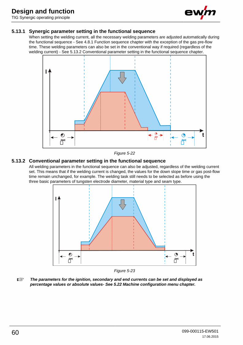
Design and function TIG Synergic operating principle
60 099-000115-EW501
17.06.2015
5.13.1 Synergic parameter setting in the functional sequence When setting the welding current, all the necessary welding parameters are adjusted automatically during
the functional sequence - See 4.8.1 Function sequence chapter with the exception of the gas pre-flow
time. These welding parameters can also be set in the conventional way if required (regardless of the
welding current) - See 5.13.2 Conventional parameter setting in the functional sequence chapter.
Figure 5-22
5.13.2 Conventional parameter setting in the functional sequence All welding parameters in the functional sequence can also be adjusted, regardless of the welding current
set. This means that if the welding current is changed, the values for the down slope time or gas post-flow
time remain unchanged, for example. The welding task still needs to be selected as before using the
three basic parameters of tungsten electrode diameter, material type and seam type.
Figure 5-23
The parameters for the ignition, secondary and end currents can be set and displayed as
percentage values or absolute values- See 5.22 Machine configuration menu chapter.

Design and function TIG Synergic operating principle
099-000115-EW501
17.06.2015 61
5.13.2.1 Set the operating principle (conventional/synergic)
NAVIGATIONENTER
+
EXIT
l
0
Figure 5-24
Display Setting/selection
Exit the menu
Exit
Machine configuration
Settings for machine functions and parameter display
Operating principle • on = synergic parameter setting (factory setting)
• off = conventional parameter setting
ENTER (enter the menu)
• Switch off machine at the main switch
• Press and hold the "welding parameters" button and switch the machine on again at the same
time.
NAVIGATION (navigating in the menu)
• Parameters are selected by pressing the "welding parameters" button.
• Set or change the parameters by turning the "welding parameter setting" rotary dial.
EXIT (leave the menu)
• Select the "Elt" menu item.
• Press the "welding parameters" button (settings will be applied, machine changes to the
ready-to-operate status).
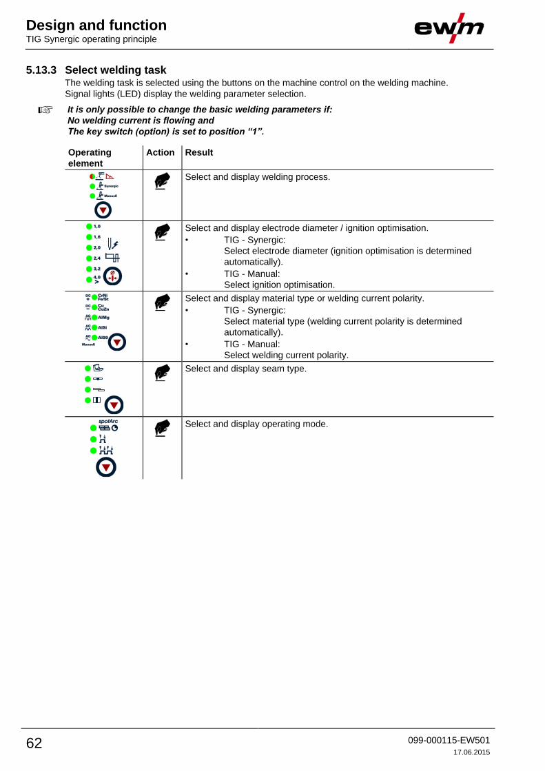
Design and function TIG Synergic operating principle
62 099-000115-EW501
17.06.2015
5.13.3 Select welding task The welding task is selected using the buttons on the machine control on the welding machine.
Signal lights (LED) display the welding parameter selection.
It is only possible to change the basic welding parameters if:
No welding current is flowing and
The key switch (option) is set to position “1”.
Operating
element
Action Result
Select and display welding process.
Select and display electrode diameter / ignition optimisation.
• TIG - Synergic:
Select electrode diameter (ignition optimisation is determined
automatically).
• TIG - Manual:
Select ignition optimisation.
Select and display material type or welding current polarity.
• TIG - Synergic:
Select material type (welding current polarity is determined
automatically).
• TIG - Manual:
Select welding current polarity.
Select and display seam type.
Select and display operating mode.

Design and function TIG Synergic operating principle
099-000115-EW501
17.06.2015 63
5.13.4 Select welding current The user has two options for setting the required welding current:
• Using the sheet metal thickness
• Directly as welding current
The welding current is displayed in the left-hand display. The “Material thickness” parameter can
be selected in the right-hand display.
Control element Action Result Display (right)
X x Press button until signal light
Material Thickness comes on.
Material thickness in
mm is displayed.
Set welding current or sheet metal thickness. Welding current and
sheet metal thickness
are displayed
5.13.5 Welding data display The following welding parameters can be displayed before (nominal values), during (actual values) or
after welding (hold values):
“Left-hand display”
Parameter Before welding
(nominal values)
During welding
(actual values)
After welding
(hold values)
Welding current
Parameter times - -
Frequency, balance - -
Parameter currents - -
“Right-hand display”
Material thickness - -
Welding voltage
JOB number - -
Program number - -
After welding the hold values are displayed. When changes are made to the settings (e.g. welding
current) after welding, the display switches to the relevant nominal values.
The right-hand display automatically switches over to the material thickness after approx. 4 seconds.
If the “Program number” signal light is on in addition to the “Material thickness” signal light, the user is in
program mode- See 5.15 Welding programs chapter.
If the “JOB number” signal light is on in addition to the “Material thickness” light, the user is in a JOB in
the free memory.

Design and function TIG Synergic operating principle
64 099-000115-EW501
17.06.2015
5.13.5.1 Welding current display (ignition, secondary, end and hotstart currents)
The welding currents for secondary current, ignition current and end current (expert menu) can be
displayed as percentages (factory setting) or absolute values on the machine display.
ENTER
+
EXIT NAVIGATION
l
0
Figure 5-25
Display Setting/selection
Exit the menu
Exit
Machine configuration
Settings for machine functions and parameter display
Welding current display (ignition, secondary, end and hotstart currents) • Pro = welding current display as a percentage of the main current (factory setting)
• Abs = absolute welding current display

Design and function TIG Synergic operating principle
099-000115-EW501
17.06.2015 65
5.13.6 Expert menu (TIG)
ENTER (enter the menu)
• Keep the "welding parameters" button pressed for 4 s.
NAVIGATION (Navigating in the menu)
• Parameters are selected by pressing the "welding parameters" button.
• Set or change the parameters by turning the "welding parameter setting" rotary dial.
EXIT (leave the menu)
• After 4 s, the machine will return automatically to the ready-to-operate status.
The expert menu includes functions and parameters which are either not set on the machine control, or
which do not require regular setting.
ENTER EXIT
4 s
NAVIGATION
4 s
Figure 5-26
Display Setting/selection
Expert menu
Slope time tS1 (main current to secondary current)
Setting: 0.00 s to 20.0 s (factory setting 0.00 s)
Slope time tS2 (secondary current to main current)
Setting: 0.00 s to 20.0 s (factory setting 0.00 s)
activArc parameter
Parameter can also be set after activating TIG activArc welding.
Display shown = factory setting.
5.13.6.1 Welding parameter setting
During the welding parameter setting process, the parameter value being set is displayed on the left-hand
display. The right-hand display shows the “Factory setting” or a variation of it upwards or downwards.
Displays, e.g. when setting the ignition current, and their meanings:
Display Meaning of the symbols shown in the right-hand display
Increase parameter value To restore the factory settings.
Factory setting Parameter value is on the optimum setting
Reduce parameter value To restore the factory settings.

Design and function TIG Synergic operating principle
66 099-000115-EW501
17.06.2015
5.13.7 Arc ignition
5.13.7.1 HF ignition
Figure 5-27
The arc is started without contact from high-voltage ignition pulses.
a) Position the welding torch in welding position over the workpiece (distance between the electrode tip
and workpiece should be approx. 2-3mm).
b) Press the torch trigger (high voltage ignition pulses ignite the arc).
c) Ignition current flows, and the welding process is continued depending on the operating mode
selected.
End the welding process: Release or press the torch trigger depending on the operating mode
selected.
5.13.7.2 Liftarc ignition
Figure 5-28
The arc is ignited on contact with the workpiece:
a) Carefully place the torch gas nozzle and tungsten electrode tip onto the workpiece and press the torch
trigger (liftarc current flowing, regardless of the main current set).
b) Incline the torch over the torch gas nozzle to produce a gap of approx. 2-3 mm between the electrode
tip and the workpiece. The arc ignites and the welding current is increased, depending on the
operating mode set, to the ignition or main current set.
c) Lift off the torch and swivel to the normal position.
Ending the welding process: Release or press the torch trigger depending on the operating mode
selected.
5.13.7.3 Automatic cut-out
The automatic cut-out function will be triggered by two conditions during the welding process:
• During the ignition phase (ignition fault) If there is no welding current within 3s after starting
the welding.
• During the welding phase (arc interruption) If the arc is interrupted for longer than 3s.
In both cases, the welding machine ends the ignition or welding process immediately.
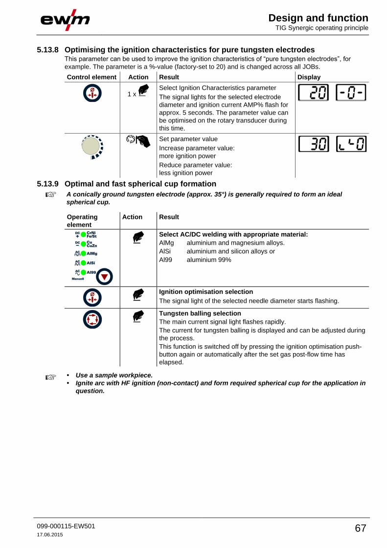
Design and function TIG Synergic operating principle
099-000115-EW501
17.06.2015 67
5.13.8 Optimising the ignition characteristics for pure tungsten electrodes This parameter can be used to improve the ignition characteristics of “pure tungsten electrodes”, for
example. The parameter is a %-value (factory-set to 20) and is changed across all JOBs.
Control element Action Result Display
1 x
Select Ignition Characteristics parameter
The signal lights for the selected electrode
diameter and ignition current AMP% flash for
approx. 5 seconds. The parameter value can
be optimised on the rotary transducer during
this time.
Set parameter value
Increase parameter value:
more ignition power
Reduce parameter value:
less ignition power
5.13.9 Optimal and fast spherical cup formation
A conically ground tungsten electrode (approx. 35°) is generally required to form an ideal
spherical cup.
Operating
element
Action Result
Select AC/DC welding with appropriate material:
AlMg aluminium and magnesium alloys.
AlSi aluminium and silicon alloys or
Al99 aluminium 99%
Ignition optimisation selection
The signal light of the selected needle diameter starts flashing.
Tungsten balling selection
The main current signal light flashes rapidly.
The current for tungsten balling is displayed and can be adjusted during
the process.
This function is switched off by pressing the ignition optimisation push-
button again or automatically after the set gas post-flow time has
elapsed.
• Use a sample workpiece.
• Ignite arc with HF ignition (non-contact) and form required spherical cup for the application in
question.
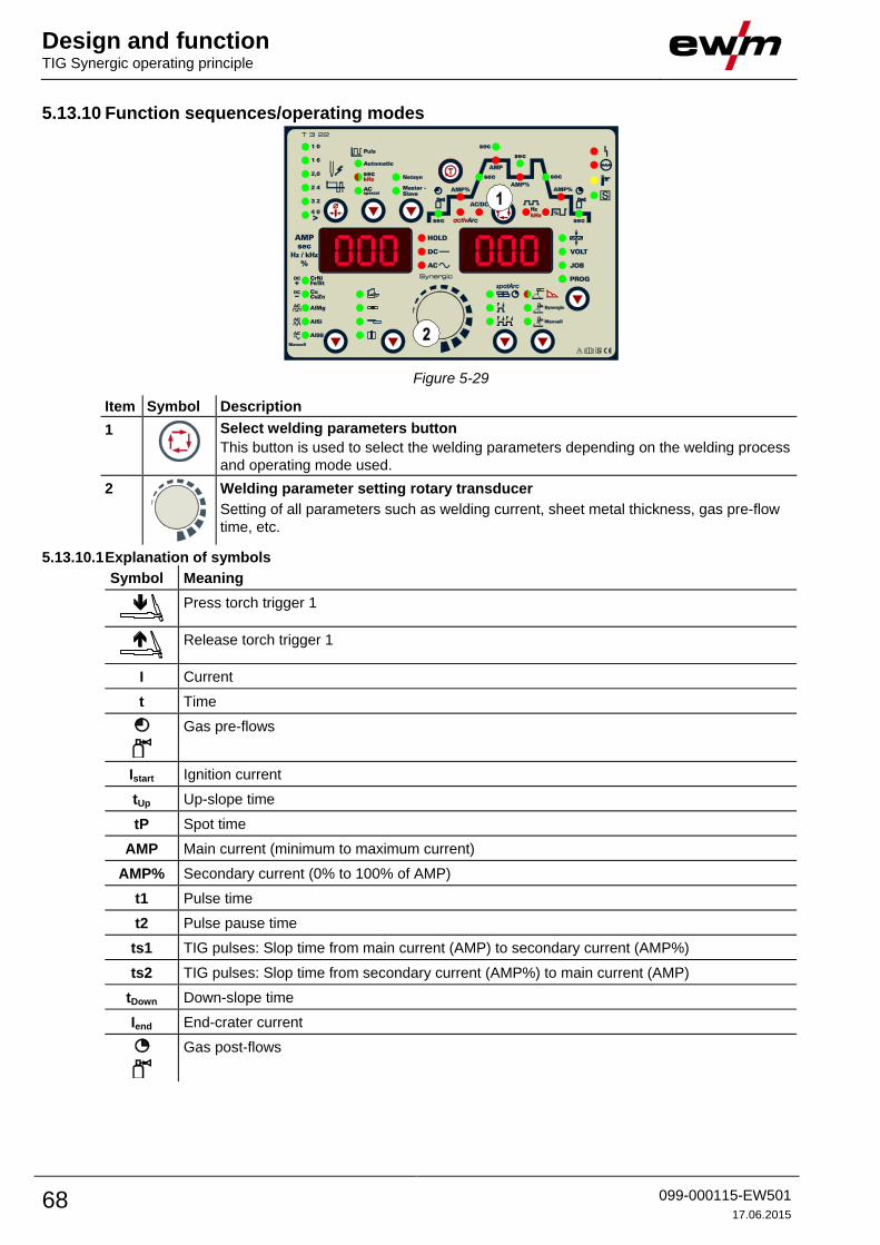
Design and function TIG Synergic operating principle
68 099-000115-EW501
17.06.2015
5.13.10 Function sequences/operating modes
Figure 5-29
Item Symbol Description 0
1
Select welding parameters button
This button is used to select the welding parameters depending on the welding process
and operating mode used.
2
Welding parameter setting rotary transducer
Setting of all parameters such as welding current, sheet metal thickness, gas pre-flow
time, etc.
5.13.10.1 Explanation of symbols
Symbol Meaning
Press torch trigger 1
Release torch trigger 1
I Current
t Time
Gas pre-flows
Istart Ignition current
tUp Up-slope time
tP Spot time
AMP Main current (minimum to maximum current)
AMP% Secondary current (0% to 100% of AMP)
t1 Pulse time
t2 Pulse pause time
ts1 TIG pulses: Slop time from main current (AMP) to secondary current (AMP%)
ts2 TIG pulses: Slop time from secondary current (AMP%) to main current (AMP)
tDown Down-slope time
Iend End-crater current
Gas post-flows

Design and function TIG Synergic operating principle
099-000115-EW501
17.06.2015 69
5.13.10.2 Non-latched mode
Figure 5-30
1st cycle:
• Press and hold torch trigger 1.
• The gas pre-flow time elapses.
• HF ignition pulses jump from the electrode to the workpiece, the arc ignites.
• The welding current flows and immediately assumes the value set for the ignition current Istart.
• HF is switched off.
• The welding current increases with the adjusted up-slope time to the main current AMP.
If torch trigger 2 is pressed in addition to torch trigger 1 during the main current phase, the
welding current drops at the slope time set (tS1) to the secondary current AMP%.
After torch trigger 2 is released, the welding current rises at the slope time set (tS2) back to the
main current AMP.
2nd cycle:
• Release torch trigger 1.
• The main current falls in the set down-slope time to the
end-crater current Iend (minimum current).
If the 1st torch trigger is pressed during the down-slope time,
the welding current returns to the main current AMP set.
• The main current reaches the end-crater current Iend, the arc extinguishes.
• The set gas post-flow time elapses.
When the foot-operated remote control RTF is connected, the machine switches automatically to
non-latched operation.
The up- and down-slopes are switched off.
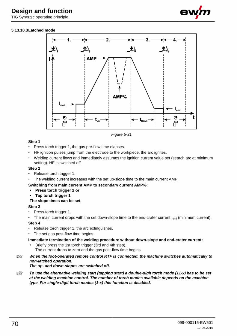
Design and function TIG Synergic operating principle
70 099-000115-EW501
17.06.2015
5.13.10.3 Latched mode
Figure 5-31
Step 1
• Press torch trigger 1, the gas pre-flow time elapses.
• HF ignition pulses jump from the electrode to the workpiece, the arc ignites.
• Welding current flows and immediately assumes the ignition current value set (search arc at minimum
setting). HF is switched off.
Step 2
• Release torch trigger 1.
• The welding current increases with the set up-slope time to the main current AMP.
Switching from main current AMP to secondary current AMP%:
• Press torch trigger 2 or
• Tap torch trigger 1
The slope times can be set.
Step 3
• Press torch trigger 1.
• The main current drops with the set down-slope time to the end-crater current Iend (minimum current).
Step 4
• Release torch trigger 1, the arc extinguishes.
• The set gas post-flow time begins.
Immediate termination of the welding procedure without down-slope and end-crater current:
• Briefly press the 1st torch trigger (3rd and 4th step).
The current drops to zero and the gas post-flow time begins.
When the foot-operated remote control RTF is connected, the machine switches automatically to
non-latched operation.
The up- and down-slopes are switched off.
To use the alternative welding start (tapping start) a double-digit torch mode (11-x) has to be set
at the welding machine control. The number of torch modes available depends on the machine
type. For single-digit torch modes (1-x) this function is disabled.
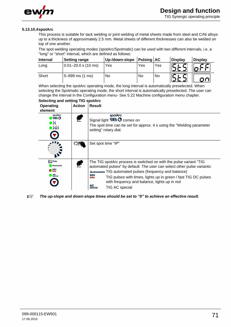
Design and function TIG Synergic operating principle
099-000115-EW501
17.06.2015 71
5.13.10.4 spotArc
This process is suitable for tack welding or joint welding of metal sheets made from steel and CrNi alloys
up to a thickness of approximately 2.5 mm. Metal sheets of different thicknesses can also be welded on
top of one another.
The spot welding operating modes (spotArc/Spotmatic) can be used with two different intervals, i.e. a
"long" or "short" interval, which are defined as follows:
Interval Setting range Up-/down-slope Pulsing AC Display Display
Long 0.01–20.0 s (10 ms) Yes Yes Yes
Short 5–999 ms (1 ms) No No No
When selecting the spotArc operating mode, the long interval is automatically preselected. When
selecting the Spotmatic operating mode, the short interval is automatically preselected. The user can
change the interval in the Configuration menu- See 5.22 Machine configuration menu chapter.
Selecting and setting TIG spotArc
Operating
element
Action Result
Signal light comes on
The spot time can be set for approx. 4 s using the "Welding parameter
setting" rotary dial.
Set spot time "tP"
The TIG spotArc process is switched on with the pulse variant "TIG
automated pulses" by default. The user can select other pulse variants:
TIG automated pulses (frequency and balance)
TIG pulses with times, lights up in green / fast TIG DC pulses
with frequency and balance, lights up in red
TIG AC special
The up-slope and down-slope times should be set to “0” to achieve an effective result.

Design and function TIG Synergic operating principle
72 099-000115-EW501
17.06.2015
Figure 5-32
As an example the process is shown with HF ignition. Arc ignition with lift arc is also possible, however-
See 5.13.7 Arc ignition chapter.
Sequence:
• Press and hold torch trigger 1.
• The gas pre-flow time elapses.
• HF ignition pulses jump from the electrode to the workpiece, the arc ignites.
• The welding current flows and immediately assumes the value set for the ignition current Istart.
• HF is switched off.
• The welding current increases in the adjusted up-slope time to the main current AMP.
The process ends when the set spotArc time elapses or if the torch trigger is released
prematurely.
spotArc/pulse variants table:
Process Pulse variants
TIG DC Automated pulses (factory setting)
(lights up in green) Pulses (thermal pulses)
(lights up in red) kHz pulse (metallurgic pulses)
No pulses
TIG AC (lights up in green) Pulses (thermal pulses)
AC special
No pulses

Design and function TIG Synergic operating principle
099-000115-EW501
17.06.2015 73
5.13.10.5 Spotmatic
This function must be enabled before use- See 5.22 Machine configuration menu chapter.
In contrast to the spotarc operating mode, the arc ignites not by pressing the torch trigger as is usual, but
by shortly touching the tungsten electrode against the workpiece. The torch trigger is used for process
activation. The process can be activated separately for each spot or permanently- See 5.22 Machine
configuration menu chapter:
• Separate process activation:
The welding process has to be reactivated for every arc ignition by pressing the torch trigger.
• Permanent process activation:
The welding process is activated by pressing the torch trigger once. The following arc ignitions are
initiated by shortly touching the tungsten electrode against the workpiece.
Selection and adjustment are made in the same way as with spotArc operating mode "- See
5.13.10.4 spotArc chapter".
Figure 5-33
As an example the process is shown with HF ignition. Arc ignition with lift arc is also possible, however-
See 5.13.7 Arc ignition chapter.
Select the process activation type- See 5.22 Machine configuration menu chapter.
Up- and down-slope times possible for long setting range of the spot time (0.01 s - 20.0 s) only.
Press and release torch trigger (tap) to activate the welding process.
Touch the torch gas nozzle and tungsten electrode tip carefully against the workpiece.
Incline the torch over the torch gas nozzle until there is a gap of approx. 2-3 mm between the
electrode tip and the workpiece. Shielding gas flows in the set gas pre-flow time. The arc ignites and
the previously set ignition current (Istart) flows.
The main current phase ends when the set spotArc time expires.
The welding current drops in the set down-slope time to the end current (Iend).
The gas post-flow time expires and the welding process ends.
Press and release torch trigger (tap) to reactivate the welding process (only for separate process
activation). Touching the torch with the tungsten electrode tip again against the workpiece will
initiate the next welding processes.

Design and function TIG Synergic operating principle
74 099-000115-EW501
17.06.2015
5.13.10.6 Non-latched operation, version C
Figure 5-34
1st cycle
• Press torch trigger 1, the gas pre-flow time elapses.
• HF ignition pulses jump from the electrode to the workpiece, the arc ignites.
• Welding current flows and immediately adopts the ignition current value set (search arc at minimum
setting). HF is switched off.
2nd cycle
• Release torch trigger 1.
• The welding current increases in the set up-slope time to the main current AMP.
Pressing torch trigger 1 starts the slope (tS1) from main current AMP to secondary current
AMP%. Releasing the torch trigger starts the slope (tS2) from the secondary current AMP% back
to the main current AMP. This process can be repeated as often as required.
The welding process is ended by the arc interruption in the secondary current (removing the
torch from the workpiece until the arc is extinguished).
The slope times can be set- See 5.22 Machine configuration menu chapter.
This operating mode needs to be activated- See 5.22 Machine configuration menu chapter
section.

Design and function TIG Synergic operating principle
099-000115-EW501
17.06.2015 75
5.13.11 Pulses, function sequences
The function sequences in pulses basically behave in the same way as in standard welding, but
during the main current phase there is a continual switching back and forth between the pulse
and pause currents at the relevant times.
The pulse function can also be deactivated if necessary during the upslope and downslope
phases- See 5.22 Machine configuration menu chapter.
5.13.11.1 TIG pulses – non-latched operation
Figure 5-35
5.13.11.2 TIG pulses - latched operation
Figure 5-36
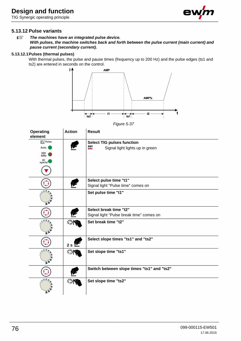
Design and function TIG Synergic operating principle
76 099-000115-EW501
17.06.2015
5.13.12 Pulse variants
The machines have an integrated pulse device.
With pulses, the machine switches back and forth between the pulse current (main current) and
pause current (secondary current).
5.13.12.1 Pulses (thermal pulses)
With thermal pulses, the pulse and pause times (frequency up to 200 Hz) and the pulse edges (ts1 and
ts2) are entered in seconds on the control.
Figure 5-37
Operating
element
Action Result
Select TIG pulses function
Signal light lights up in green
Select pulse time "t1"
Signal light "Pulse time" comes on
Set pulse time "t1"
Select break time "t2"
Signal light "Pulse break time" comes on
Set break time "t2"
2 s
Select slope times "ts1" and "ts2"
Set slope time "ts1"
Switch between slope times "ts1" and "ts2"
Set slope time "ts2"
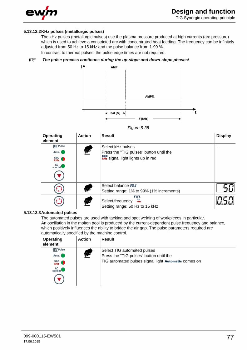
Design and function TIG Synergic operating principle
099-000115-EW501
17.06.2015 77
5.13.12.2 KHz pulses (metallurgic pulses)
The kHz pulses (metallurgic pulses) use the plasma pressure produced at high currents (arc pressure)
which is used to achieve a constricted arc with concentrated heat feeding. The frequency can be infinitely
adjusted from 50 Hz to 15 kHz and the pulse balance from 1-99 %.
In contrast to thermal pulses, the pulse edge times are not required.
The pulse process continues during the up-slope and down-slope phases!
Figure 5-38
Operating
element
Action Result Display
Select kHz pulses
Press the "TIG pulses" button until the
signal light lights up in red
-
Select balance
Setting range: 1% to 99% (1% increments)
Select frequency
Setting range: 50 Hz to 15 kHz
5.13.12.3 Automated pulses
The automated pulses are used with tacking and spot welding of workpieces in particular.
An oscillation in the molten pool is produced by the current-dependent pulse frequency and balance,
which positively influences the ability to bridge the air gap. The pulse parameters required are
automatically specified by the machine control.
Operating
element
Action Result
Select TIG automated pulses
Press the "TIG pulses" button until the
TIG automated pulses signal light comes on

Design and function TIG Synergic operating principle
78 099-000115-EW501
17.06.2015
5.13.12.4 AC pulses
(AC pulse, max. 50Hz)
Setting: +
AMP = pulse current
AMP% = pulse pause current / basic current
tpuls = pulse time
tpause = pulse pause time
Figure 5-39
5.13.12.5 AC special
Application: e.g. for welding thick metal sheets onto thin metal sheets.
Operating
element
Action Result
Select TIG AC special
Press the "TIG pulses" button until the signal light comes on
AMP = AC current phase pulse current
AMP% = DC phase pulse pause current
tpulse = Pulse time; AC phase time
tbreak = Pulse break time; DC phase time
Figure 5-40
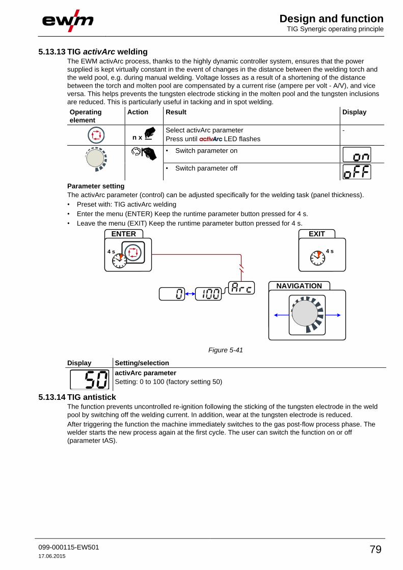
Design and function TIG Synergic operating principle
099-000115-EW501
17.06.2015 79
5.13.13 TIG activArc welding The EWM activArc process, thanks to the highly dynamic controller system, ensures that the power
supplied is kept virtually constant in the event of changes in the distance between the welding torch and
the weld pool, e.g. during manual welding. Voltage losses as a result of a shortening of the distance
between the torch and molten pool are compensated by a current rise (ampere per volt - A/V), and vice
versa. This helps prevents the tungsten electrode sticking in the molten pool and the tungsten inclusions
are reduced. This is particularly useful in tacking and in spot welding.
Operating
element
Action Result Display
n x
Select activArc parameter
Press until LED flashes
-
• Switch parameter on
• Switch parameter off
Parameter setting
The activArc parameter (control) can be adjusted specifically for the welding task (panel thickness).
• Preset with: TIG activArc welding
• Enter the menu (ENTER) Keep the runtime parameter button pressed for 4 s.
• Leave the menu (EXIT) Keep the runtime parameter button pressed for 4 s.
NAVIGATION
ENTER
4 s
EXIT
4 s
Figure 5-41
Display Setting/selection
activArc parameter
Setting: 0 to 100 (factory setting 50)
5.13.14 TIG antistick The function prevents uncontrolled re-ignition following the sticking of the tungsten electrode in the weld
pool by switching off the welding current. In addition, wear at the tungsten electrode is reduced.
After triggering the function the machine immediately switches to the gas post-flow process phase. The
welder starts the new process again at the first cycle. The user can switch the function on or off
(parameter tAS).
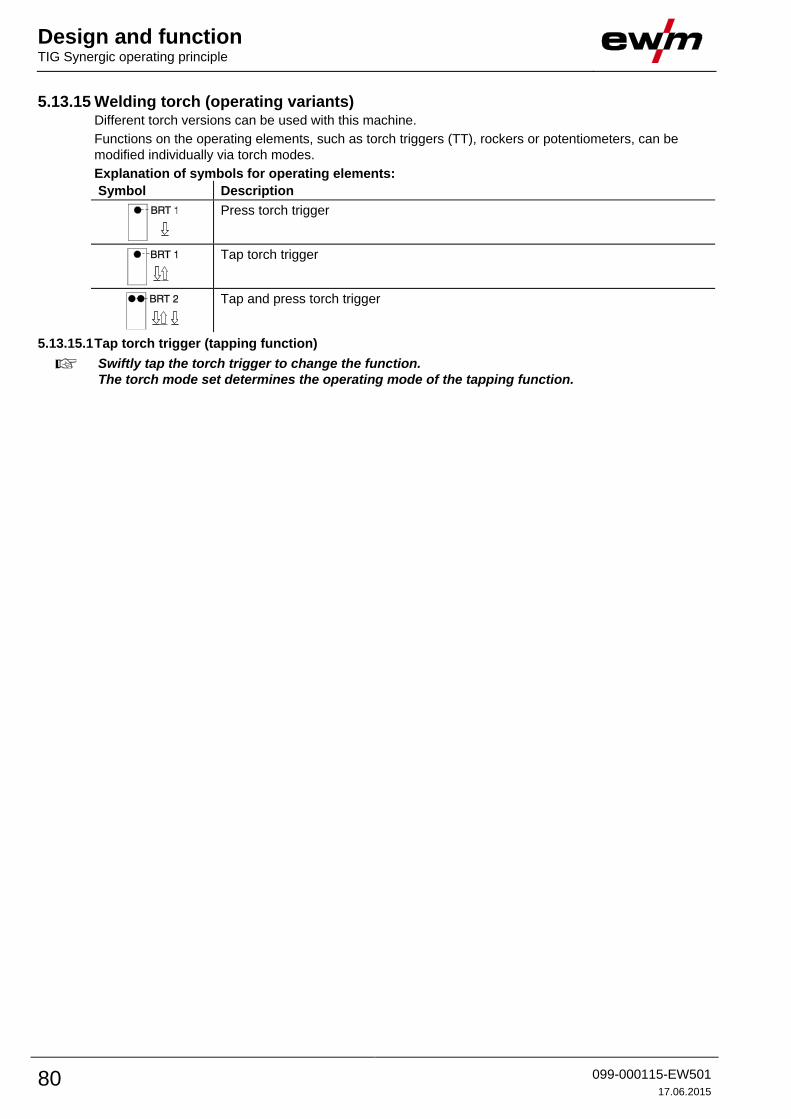
Design and function TIG Synergic operating principle
80 099-000115-EW501
17.06.2015
5.13.15 Welding torch (operating variants) Different torch versions can be used with this machine.
Functions on the operating elements, such as torch triggers (TT), rockers or potentiometers, can be
modified individually via torch modes.
Explanation of symbols for operating elements:
Symbol Description
Press torch trigger
Tap torch trigger
Tap and press torch trigger
5.13.15.1 Tap torch trigger (tapping function)
Swiftly tap the torch trigger to change the function.
The torch mode set determines the operating mode of the tapping function.

Design and function TIG Synergic operating principle
099-000115-EW501
17.06.2015 81
5.13.16 Torch mode and up/down speed setting The user has the modes 1 to 6 and modes 11 to 16 available. Modes 11 to 16 include the same function
options as 1 to 6, but without tapping function for the secondary current.
The function options in the individual modes can be found in the tables for the corresponding torch types.
The welding process can of course be switched on and off in all modes using torch trigger 1 (TT 1).
ENTER
+
EXIT NAVIGATION
l
0
Figure 5-42
Display Setting/selection
Exit the menu
Exit
Torch configuration menu
Set welding torch functions
Torch mode (factory setting 1)
Up-/Down speed
Increase value = rapid current change (factory setting 10)
Reduce value = slow current change
Only the modes listed are suitable for the corresponding torch types.

Design and function TIG Synergic operating principle
82 099-000115-EW501
17.06.2015
5.13.16.1 Standard TIG torch (5-pole)
Standard torch with one torch trigger:
Diagram Operating
elements
Explanation of symbols
BRT1 = Torch trigger 1 (welding current on/off;
secondary current via tapping function)
Functions mode Operating
elements
Welding current On/Off 1
(factory-set)
Secondary current (Latched mode)
Standard torch with two torch triggers:
Diagram Operating
elements
Explanation of symbols
BRT1 = torch trigger 1
BRT2 = torch trigger 2
Functions mode Operating
elements
Welding current On/Off
1
(factory-set)
Secondary current
Secondary current (tapping mode) / (latched mode)
Welding current On/Off
3
Secondary current (tapping mode) / (latched mode)
Up function
Down function
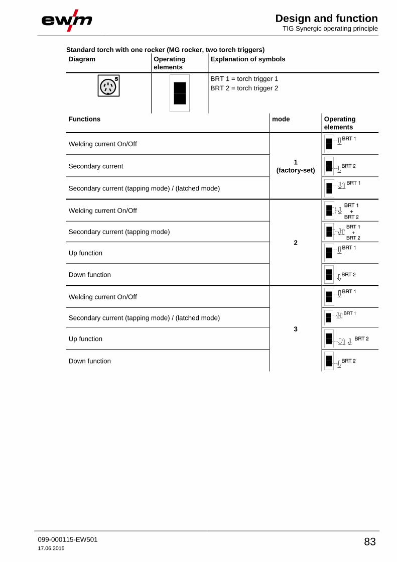
Design and function TIG Synergic operating principle
099-000115-EW501
17.06.2015 83
Standard torch with one rocker (MG rocker, two torch triggers)
Diagram Operating
elements
Explanation of symbols
BRT 1 = torch trigger 1
BRT 2 = torch trigger 2
Functions mode Operating
elements
Welding current On/Off
1
(factory-set)
Secondary current
Secondary current (tapping mode) / (latched mode)
Welding current On/Off
2
Secondary current (tapping mode)
Up function
Down function
Welding current On/Off
3
Secondary current (tapping mode) / (latched mode)
Up function
Down function
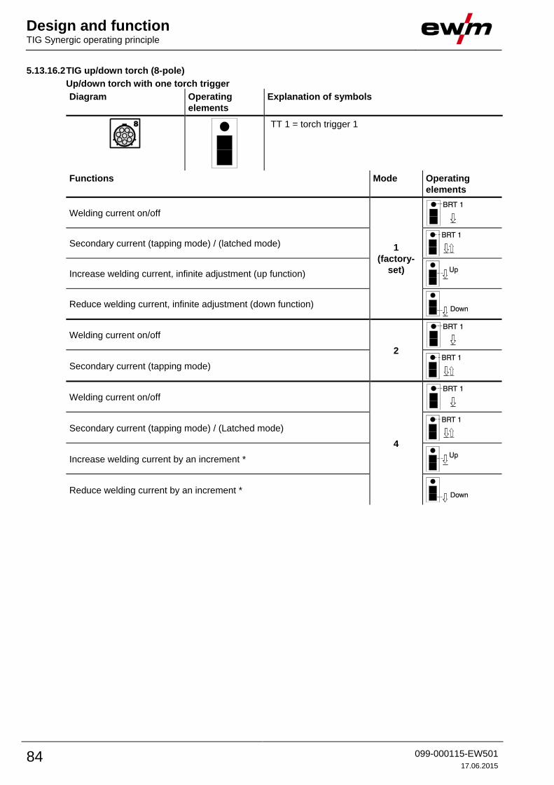
Design and function TIG Synergic operating principle
84 099-000115-EW501
17.06.2015
5.13.16.2 TIG up/down torch (8-pole)
Up/down torch with one torch trigger
Diagram Operating
elements
Explanation of symbols
TT 1 = torch trigger 1
Functions Mode Operating
elements
Welding current on/off
1
(factory-
set)
Secondary current (tapping mode) / (latched mode)
Increase welding current, infinite adjustment (up function)
Reduce welding current, infinite adjustment (down function)
Welding current on/off
2
Secondary current (tapping mode)
Welding current on/off
4
Secondary current (tapping mode) / (Latched mode)
Increase welding current by an increment *
Reduce welding current by an increment *

Design and function TIG Synergic operating principle
099-000115-EW501
17.06.2015 85
Up/down torch with two torch triggers
Diagram Operating
elements
Explanation of symbols
TT 1 = torch trigger 1 (left)
TT 2 = torch trigger 2 (right)
Functions Mode Operating
elements
Welding current on/off
1
(factory-
set)
Secondary current
Secondary current (tapping mode) / (latched mode)
Increase welding current, infinite adjustment (up function)
Reduce welding current, infinite adjustment (down function)
Welding current on/off
2
Secondary current
Secondary current (tapping mode)
Welding current on/off
4
Secondary current
Secondary current (tapping mode)
Increase welding current by an increment *
Reduce welding current by an increment *
* - See 5.13.16.7 Setting the first increment chapter
Gas test 4 > 3 s
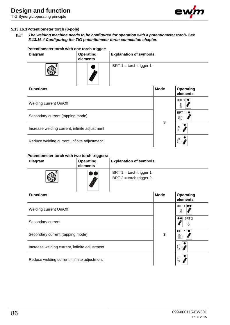
Design and function TIG Synergic operating principle
86 099-000115-EW501
17.06.2015
5.13.16.3 Potentiometer torch (8-pole)
The welding machine needs to be configured for operation with a potentiometer torch- See
5.13.16.4 Configuring the TIG potentiometer torch connection chapter.
Potentiometer torch with one torch trigger:
Diagram Operating
elements
Explanation of symbols
BRT 1 = torch trigger 1
Functions Mode Operating
elements
Welding current On/Off
3
Secondary current (tapping mode)
Increase welding current, infinite adjustment
Reduce welding current, infinite adjustment
Potentiometer torch with two torch triggers:
Diagram Operating
elements
Explanation of symbols
BRT 1 = torch trigger 1
BRT 2 = torch trigger 2
Functions Mode Operating
elements
Welding current On/Off
3
Secondary current
Secondary current (tapping mode)
Increase welding current, infinite adjustment
Reduce welding current, infinite adjustment
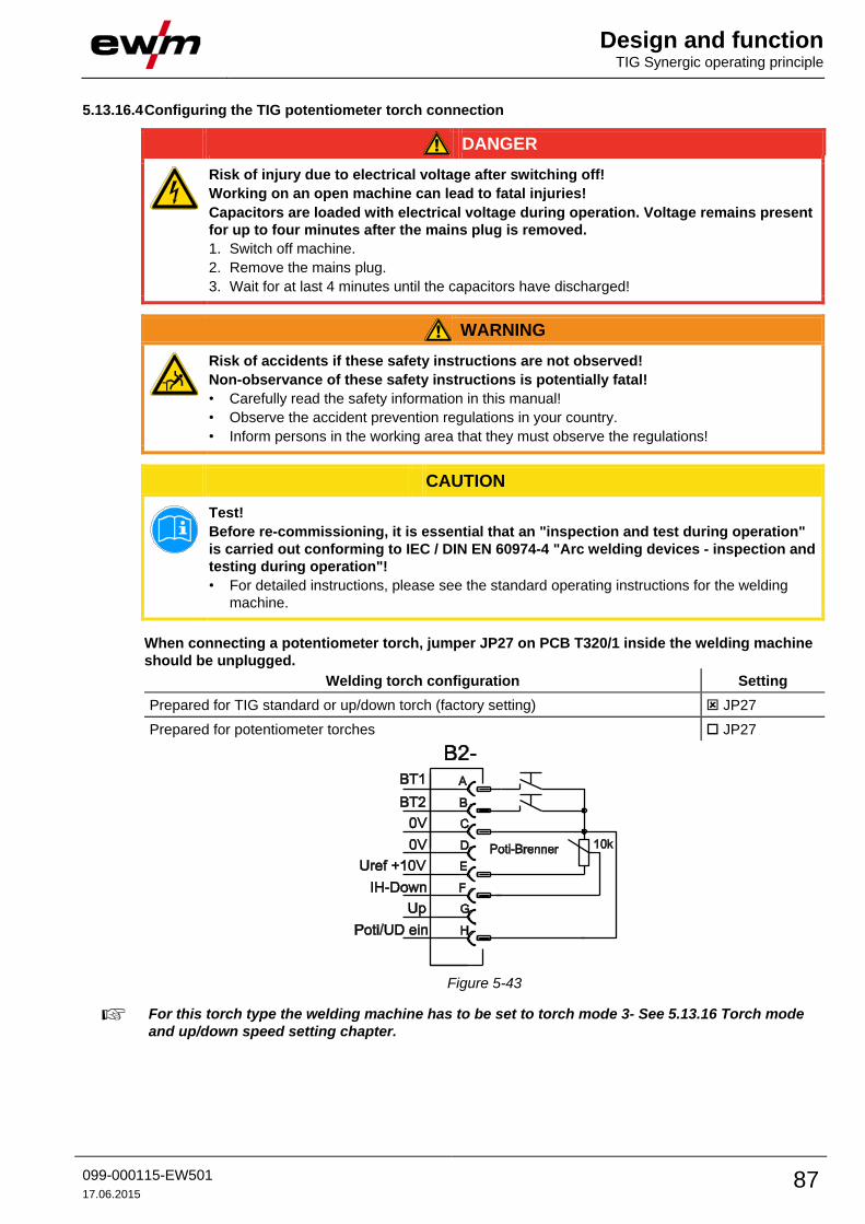
Design and function TIG Synergic operating principle
099-000115-EW501
17.06.2015 87
5.13.16.4 Configuring the TIG potentiometer torch connection
DANGER
Risk of injury due to electrical voltage after switching off!
Working on an open machine can lead to fatal injuries!
Capacitors are loaded with electrical voltage during operation. Voltage remains present
for up to four minutes after the mains plug is removed.
1. Switch off machine.
2. Remove the mains plug.
3. Wait for at last 4 minutes until the capacitors have discharged!
WARNING
Risk of accidents if these safety instructions are not observed!
Non-observance of these safety instructions is potentially fatal!
• Carefully read the safety information in this manual!
• Observe the accident prevention regulations in your country.
• Inform persons in the working area that they must observe the regulations!
CAUTION
Test!
Before re-commissioning, it is essential that an "inspection and test during operation"
is carried out conforming to IEC / DIN EN 60974-4 "Arc welding devices - inspection and
testing during operation"!
• For detailed instructions, please see the standard operating instructions for the welding
machine.
When connecting a potentiometer torch, jumper JP27 on PCB T320/1 inside the welding machine
should be unplugged.
Welding torch configuration Setting
Prepared for TIG standard or up/down torch (factory setting) JP27
Prepared for potentiometer torches JP27
Figure 5-43
For this torch type the welding machine has to be set to torch mode 3- See 5.13.16 Torch mode
and up/down speed setting chapter.

Design and function TIG Synergic operating principle
88 099-000115-EW501
17.06.2015
5.13.16.5 RETOX TIG torch (12-pole)
For operation with this welding torch, the welding machine must be equipped with the retrofit
option "ON 12POL RETOX TIG" (12-pole torch connection socket)!
Diagram Operating elements Explanation of symbols
TT= torch trigger
Functions Mode Operating
elements
Welding current on/off
1
(ex works)
TT 1
Secondary current TT 2
Secondary current (tapping function) TT 1 (tapping)
Increase welding current (up function) TT 3
Reduce welding current (down function) TT 4
Modes 2 and 3 are not used with this type of torch or, respectively, are not appropriate.
Welding current on/off
4
TT 1
Secondary current TT 2
Secondary current (tapping function) TT 1 (tapping)
Raise welding current in stages (setting the first increment) TT 3
Decrease welding current in stages (setting the first decrement) TT 4
Switchover between Up-Down and JOB changeover TT 2 (tapping)
Increase JOB number TT 3
Decrease JOB number TT 4
Gas test TT 2 (3 s)
Welding current on/off
5
TT 1
Secondary current TT 2
Secondary current (tapping function) TT 1 (tapping)
Increase program number TT 3
Decrease program number TT 4
Switchover between Up-Down and JOB changeover TT 2 (tapping)
Increase JOB number TT 3
Decrease JOB number TT 4
Gas test TT 2 (3 s)
Welding current on/off
6
TT 1
Secondary current TT 2
Secondary current (tapping function) TT 1 (tapping)
Increase welding current, infinite adjustment (up function) TT 3
Reduce welding current, infinite adjustment (down function) TT 4
Switchover between Up-Down and JOB changeover TT 2 (tapping)
Increase JOB number TT 3
Decrease JOB number TT 4
Gas test TT 2 (3 s)
JOB switching requirements:
• Set JOB range.
• Load JOB in the defined range.

Design and function TIG Synergic operating principle
099-000115-EW501
17.06.2015 89
5.13.16.6 Specifying max. no. of accessible JOBs
This function can be used to specify the maximum number of JOBs which can be retrieved from the free
memory. The factory setting is for 10 JOBs to be accessible on the welding machine, but this figure can
be increased to up to 128 if required.
The first JOB in the free memory is JOB 129. With the factory setting of 10 JOBs, this equates to JOB
numbers 129 to 138. The first JOB can be set as required.
The following graphic gives an example with the settings for max. JOBs available = 5 and first available
JOB = 145. This gives the available JOBs 145 to 150.
Figure 5-44
ENTER
+
EXIT NAVIGATION
l
0
Figure 5-45
Display Setting/selection
Exit the menu
Exit
Torch configuration menu
Set welding torch functions
Get JOB number Set maximum selectable jobs (setting: 1 to 128, factory setting 10).
Additional parameter after activating the BLOCK JOB function.
Start JOB
Set first JOB to get (setting: 129 to 256, factory setting 129).
The setting of the max. number of JOBs is intended solely for torch modes 4, 5 and 6 or 14, 15
and 16 (no tapping function).
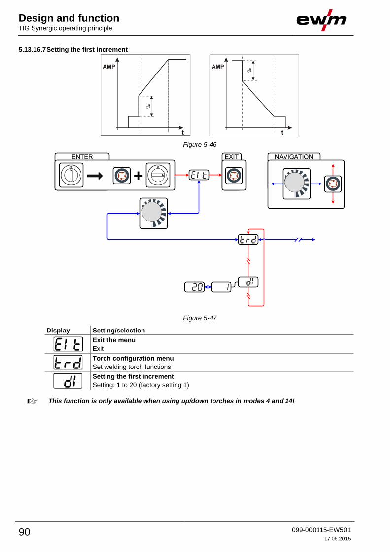
Design and function TIG Synergic operating principle
90 099-000115-EW501
17.06.2015
5.13.16.7 Setting the first increment
Figure 5-46
ENTER
+
EXIT NAVIGATION
l
0
Figure 5-47
Display Setting/selection
Exit the menu
Exit
Torch configuration menu
Set welding torch functions
Setting the first increment
Setting: 1 to 20 (factory setting 1)
This function is only available when using up/down torches in modes 4 and 14!

Design and function MMA welding
099-000115-EW501
17.06.2015 91
5.14 MMA welding
CAUTION
Risk of being crushed or burnt.
When replacing spent or new stick electrodes
• Switch off machine at the main switch
• Wear appropriate safety gloves
• Use insulated tongs to remove spent stick electrodes or to move welded workpieces and
• Always put the electrode holder down on an insulated surface.
Shielding gas connection!
During MMA welding open circuit voltage is applied at the shielding gas connection
(G¼" connecting nipple).
• Place yellow insulating cap on the G¼" connection nipple (protects against electrical
voltage and dirt).
5.14.1 Connecting the electrode holder and workpiece lead
Figure 5-48
Item Symbol Description 0
1
Electrode holder
2
Connection socket, “-” welding current
Electrode holder connection
3
Workpiece
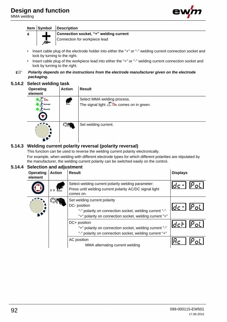
Design and function MMA welding
92 099-000115-EW501
17.06.2015
Item Symbol Description 0
4
Connection socket, “+” welding current
Connection for workpiece lead
• Insert cable plug of the electrode holder into either the "+" or "-" welding current connection socket and
lock by turning to the right.
• Insert cable plug of the workpiece lead into either the "+" or "-" welding current connection socket and
lock by turning to the right.
Polarity depends on the instructions from the electrode manufacturer given on the electrode
packaging.
5.14.2 Select welding task Operating
element
Action Result
Select MMA welding process.
The signal light comes on in green.
Set welding current.
5.14.3 Welding current polarity reversal (polarity reversal) This function can be used to reverse the welding current polarity electronically.
For example, when welding with different electrode types for which different polarities are stipulated by
the manufacturer, the welding current polarity can be switched easily on the control.
5.14.4 Selection and adjustment
Operating
element
Action Result Displays
x x
Select welding current polarity welding parameter:
Press until welding current polarity AC/DC signal light
comes on.
Set welding current polarity
DC- position
"-" polarity on connection socket, welding current "-"
"+" polarity on connection socket, welding current "+"
DC+ position
"+" polarity on connection socket, welding current "-"
"-" polarity on connection socket, welding current "+"
AC position
MMA alternating current welding

Design and function MMA welding
099-000115-EW501
17.06.2015 93
5.14.5 Frequency and balance setting Operating
element
Action Result Displays
Switch on welding current polarity "AC" - See 5.14.3 Welding current polarity reversal (polarity reversal)
chapter
x x
Select the welding parameter alternating current
frequency. Press until signal light comes on.
Set the alternating current frequency.
Factory setting, see displays
x x
Select the welding parameter alternating current
balance. Press until signal light comes on.
Set the alternating current balance.
Factory setting, see displays
5.14.6 Hotstart The hotstart device improves the ignition of the stick electrodes using an increased ignition current.
a) = Hotstart time
b) = Hotstart current
I = Welding current
t = Time
5.14.6.1 Hotstart current
Control element Action Result Displays
x x
Select hotstart current welding parameter:
Press until hotstart current signal light AMP%
comes on.
Set hotstart current.
The factory setting is a value as a percentage of
the selected main current. To set an absolute value
for the hotstart current, - See 5.22 Machine
configuration menu chapter
Percentage display:
Absolute display:

Design and function MMA welding
94 099-000115-EW501
17.06.2015
5.14.6.2 Hotstart time
Control element Action Result Displays
Select hotstart time welding parameter:
Press until the hotstart time signal light sec comes
on.
Set hotstart time.
5.14.7 Arcforce During the welding process, arcforce prevents the electrode sticking in the weld pool with increases in
current. This makes it easier to weld large-drop melting electrode types at low current strengths with a
short arc in particular.
Operating
element
Action Result Displays
1 x Select arcforcing welding parameter.
The signal light comes on in red.
Set arcforcing.
-40 = rutile electrode types
0 = basic electrode types
+40 = cellulose electrode types
5.14.8 Antistick
Anti-stick prevents the electrode from annealing.
If the electrode sticks in spite of the Arcforce device, the machine
automatically switches over to the minimum current within about 1
second to prevent the electrode from overheating. Check the welding
current setting and correct according to the welding task!

Design and function MMA welding
099-000115-EW501
17.06.2015 95
5.14.9 MMA pulse welding in the vertical up position (PF) Welding characteristics:
• Especially suitable for root welding
• Fine-flaked weld surface with a TIG look for final passes
• Less finishing work thanks to less spatter
• Highly suitable for difficult electrodes
• Outstanding gap bridging with no sagging of the root side
• Less distortion thanks to controlled heat input
Operating
element
Action Result
Press the push-button until the signal light illuminates in green.
Pulse current selection, percentage dependent on the main current
Signal light AMP on
Setting range: 1% to +200% (increments of 1%, 142% ex works)
Pulse pause current selection, percentage dependent on the main current
Signal light AMP% on
Setting range: 1% to 200% (increments of 1%, 82% ex works)
Balance selection
Signal light on
Setting range: 1% to 99% (increments of 1%, 30% ex works)
Frequency selection
Signal light on
Setting range: 0.1 Hz to 500 Hz (increments of 0.1 Hz/1 Hz, 1.2 Hz ex
works)
AMP = main current
AMP% = pulse current
AMP% = pulse pause current
= frequency
= duty cycle
Figure 5-49
The default pulse parameters are pre-set in such a way that the welding current average value
corresponds to the pre-selected main current AMP.
Changes in the pulse parameters result in changes to welding current average value AMP.

Design and function Welding programs
96 099-000115-EW501
17.06.2015
5.15 Welding programs
Changes made to the other welding parameters during the course of the program have the
equivalent effect on all programs.
The change to the welding parameters is saved immediately in the JOB.
The welding machine has 16 programs, which you can change during welding.
In each selected welding task (JOB), - See 5.13.3 Select welding task chapter, 16 programs can be set,
saved and called up. In program “0” (default setting) the welding current can be infinitely adjusted across
the entire range. In programs 1-15, 15 different welding currents (incl. operating mode and pulse function)
are defined.
Example:
Program number Welding current Operating mode Pulse function
1 80A Non-latched Pulses on
2 70A Latched Pulses off
The operating mode cannot be changed during the welding process. If welding is started with program 1
(non-latched operating mode), program 2 controls the setting of ignition program 1 despite the latched
setting and is implemented to the end of the welding process.
The pulse function (pulses off, pulses on) and the welding currents are transferred from the
corresponding programs.
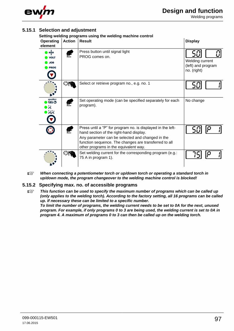
Design and function Welding programs
099-000115-EW501
17.06.2015 97
5.15.1 Selection and adjustment
Setting welding programs using the welding machine control
Operating
element
Action Result Display
Press button until signal light
PROG comes on. Welding current
(left) and program
no. (right)
Select or retrieve program no., e.g. no. 1
Set operating mode (can be specified separately for each
program).
No change
Press until a “P” for program no. is displayed in the left-
hand section of the right-hand display.
Any parameter can be selected and changed in the
function sequence. The changes are transferred to all
other programs in the equivalent way.
Set welding current for the corresponding program (e.g.:
75 A in program 1).
When connecting a potentiometer torch or up/down torch or operating a standard torch in
up/down mode, the program changeover to the welding machine control is blocked!
5.15.2 Specifying max. no. of accessible programs
This function can be used to specify the maximum number of programs which can be called up
(only applies to the welding torch). According to the factory setting, all 16 programs can be called
up. If necessary these can be limited to a specific number.
To limit the number of programs, the welding current needs to be set to 0A for the next, unused
program. For example, if only programs 0 to 3 are being used, the welding current is set to 0A in
program 4. A maximum of programs 0 to 3 can then be called up on the welding torch.

Design and function Welding programs
98 099-000115-EW501
17.06.2015
5.15.3 Example "Program with synergetic setting"
Figure 5-50
5.15.4 Example "Program with conventional setting"
Figure 5-51
5.15.5 Accessories for switching over programs
The user can change, retrieve and save programs using the following components.
Programs
Component Create and change Retrieve
Welding machine control 16 16
Up/down welding torch - 16
RETOX TIG torch - 16
RINT X11 / X12 robot interface - 16
BUSINT X11 industrial bus interface - 16
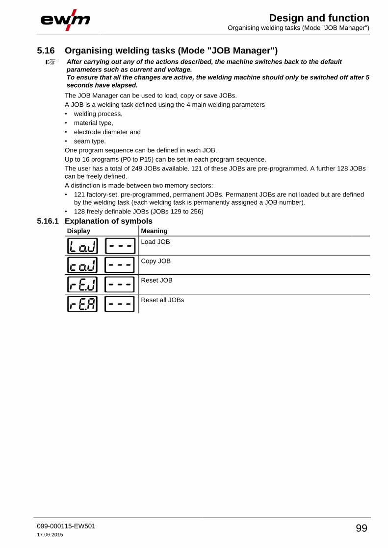
Design and function Organising welding tasks (Mode "JOB Manager")
099-000115-EW501
17.06.2015 99
5.16 Organising welding tasks (Mode "JOB Manager")
After carrying out any of the actions described, the machine switches back to the default
parameters such as current and voltage.
To ensure that all the changes are active, the welding machine should only be switched off after 5
seconds have elapsed.
The JOB Manager can be used to load, copy or save JOBs.
A JOB is a welding task defined using the 4 main welding parameters
• welding process,
• material type,
• electrode diameter and
• seam type.
One program sequence can be defined in each JOB.
Up to 16 programs (P0 to P15) can be set in each program sequence.
The user has a total of 249 JOBs available. 121 of these JOBs are pre-programmed. A further 128 JOBs
can be freely defined.
A distinction is made between two memory sectors:
• 121 factory-set, pre-programmed, permanent JOBs. Permanent JOBs are not loaded but are defined
by the welding task (each welding task is permanently assigned a JOB number).
• 128 freely definable JOBs (JOBs 129 to 256)
5.16.1 Explanation of symbols
Display Meaning
Load JOB
Copy JOB
Reset JOB
Reset all JOBs
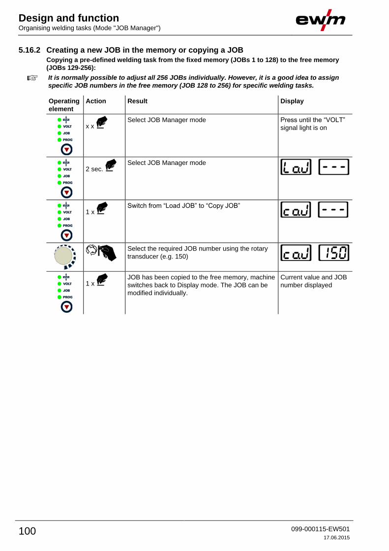
Design and function Organising welding tasks (Mode "JOB Manager")
100 099-000115-EW501
17.06.2015
5.16.2 Creating a new JOB in the memory or copying a JOB
Copying a pre-defined welding task from the fixed memory (JOBs 1 to 128) to the free memory
(JOBs 129-256):
It is normally possible to adjust all 256 JOBs individually. However, it is a good idea to assign
specific JOB numbers in the free memory (JOB 128 to 256) for specific welding tasks.
Operating
element
Action Result Display
x x Select JOB Manager mode Press until the “VOLT”
signal light is on
2 sec. Select JOB Manager mode
1 x Switch from “Load JOB” to “Copy JOB”
Select the required JOB number using the rotary
transducer (e.g. 150)
1 x JOB has been copied to the free memory, machine
switches back to Display mode. The JOB can be
modified individually.
Current value and JOB
number displayed

Design and function Organising welding tasks (Mode "JOB Manager")
099-000115-EW501
17.06.2015 101
5.16.3 Loading an existing JOB from the free memory
Operating
element
Action Result Display
x x Select JOB Manager mode Press until the “VOLT”
signal light is on
2 sec. Select JOB Manager mode
Select the required JOB number using the rotary
transducer (e.g. 150)
1 x JOB loaded, machine switches back to Display
mode.
The JOB can be customised as required.
Current value and JOB
number displayed
5.16.4 Resetting an existing JOB to the factory setting (Reset JOB)
Operating
element
Action Result Display
x x Select JOB Manager mode Press until the “VOLT”
signal light is on
2 sec. Select JOB Manager mode
2 x Switch from “Load JOB” to “Reset JOB”
Select the required JOB number using the rotary
transducer (e.g. 150)
1 x JOB reset to factory settings, machine switches
back to Display mode.
Current value and JOB
number displayed
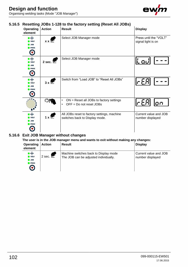
Design and function Organising welding tasks (Mode "JOB Manager")
102 099-000115-EW501
17.06.2015
5.16.5 Resetting JOBs 1-128 to the factory setting (Reset All JOBs)
Operating
element
Action Result Display
x x Select JOB Manager mode Press until the “VOLT”
signal light is on
2 sec. Select JOB Manager mode
3 x Switch from “Load JOB” to “Reset All JOBs”
• ON = Reset all JOBs to factory settings
• OFF = Do not reset JOBs
1 x All JOBs reset to factory settings, machine
switches back to Display mode.
Current value and JOB
number displayed
5.16.6 Exit JOB Manager without changes
The user is in the JOB manager menu and wants to exit without making any changes:
Operating
element
Action Result Display
2 sec. Machine switches back to Display mode
The JOB can be adjusted individually.
Current value and JOB
number displayed

Design and function Remote control
099-000115-EW501
17.06.2015 103
5.17 Remote control The remote controls are operated on the 19-pole remote control connection socket (analogue).
5.17.1 Manual remote control RT1 19POL
Functions
• Infinitely adjustable welding current (0% to 100%) depending on the preselected
main current on the welding machine.
5.17.2 RTG1 19POL manual remote control
Functions
• Infinite setting of the welding current (0% to 100%) depending on the main current
preselected at the welding machine
5.17.3 Manual remote control RTP1 19POL
Functions
• TIG/MMA
• Infinitely adjustable welding current (0% to 100%) depending on the preselected
main current on the welding machine.
• Pulse/spot/normal
• Pulse, spot and break times are infinitely adjustable.
5.17.4 Manual remote control RTP2 19POL
Functions
• TIG/MMA.
• Infinitely adjustable welding current (0% to 100%) depending on the preselected
main current on the welding machine.
• Pulse/spot/normal
• Frequency and spot times infinitely adjustable.
• Coarse adjustment of the cycle frequency.
• Pulse/pause ratio (balance) adjustable from 10% to 90%.
5.17.5 RTP3 spotArc 19POL manual remote control
Functions
• TIG / MMA.
• Infinitely adjustable welding current (0% to 100%) depending on the preselected
main current on the welding machine.
• Pulse / SpotArc spots / normal
• Frequency and spot time infinitely adjustable.
• Coarse adjustment of the pulse frequency.
• Pulse/pause ratio (balance) adjustable from 10% to 90%.
5.17.6 Manual remote control RT AC 1 19POL
Functions
• Infinitely adjustable welding current (0% to 100%) depending on the preselected
main current on the welding machine.
• AC frequency of welding current infinitely adjustable.
• AC balance (positive/negative half-wave ratio) can be set from +15% to -15%.

Design and function Remote control
104 099-000115-EW501
17.06.2015
5.17.7 Manual remote control RT PWS 1 19POL
Functions
• Infinitely adjustable welding current (0% to 100%) depending on the preselected
main current at the welding machine
• Pole reversing switch, suitable for machines with PWS function
5.17.8 Foot-operated remote control RTF1 19POL 5 M / RTF2 19POL 5 M
Functions
• Infinitely adjustable welding current (0% to 100%) depending on the preselected
main current on the welding machine.
• Start/stop welding operation (TIG)
ActivArc welding is not possible in combination with the foot-operated remote control.
Figure 5-52
Symbol Meaning
Actuate foot-operated remote control (start welding process)
Operate foot-operated remote control (set welding current according to application)
Release foot-operated remote control (end welding process)
FFr RTF ramp function
on Welding current runs in a ramp function at the specified main current
off Welding current goes immediately to the specified main current

Design and function Remote control
099-000115-EW501
17.06.2015 105
5.17.8.1 Ramp function foot-operated remote control RTF 1 / RTF 2
ENTER
+
EXIT NAVIGATION
l
0
Figure 5-53
Display Setting/selection
Exit the menu
Exit
Machine configuration (part two)
Settings for machine functions and parameter display
Ramp function Remote control RTF 1
The ramp function can be switched on and off
Switch on
Switching on machine function
Switch off
Switching off machine function

Design and function Simultaneous welding on both sides, synchronisation types
106 099-000115-EW501
17.06.2015
5.18 Simultaneous welding on both sides, synchronisation types This function is important, if two power sources are used to simultaneously weld on both sides, as is
sometimes required for welding thick aluminium materials in the PF position. This ensures that, with
alternating currents, the positive and negative pole phases are present on both power sources
simultaneously, thus avoiding the arcs negatively influencing each other.
5.18.1 Synchronisation via mains voltage (50Hz / 60Hz)
This application relates to two types of synchronisation:
• Synchronisation between a Tetrix series machine and a competitor machine.
• Synchronisation between two Tetrix series machines.
Phase sequences and rotating fields of the supply voltages must be identical for both welding
machines.
If this is not the case, the energy input into the weld pool will be negatively affected.
Use the "Phase sequence changeover“ rotary switch to correct the phase difference in steps of
60° (0°, 60°, 120°, 180°, 240° and 300°).
An optimum phase correction will directly achieve better welding results.
Operating
element
Action Result
Select "Synchronisation types" parameter:
Press until signal light comes on.
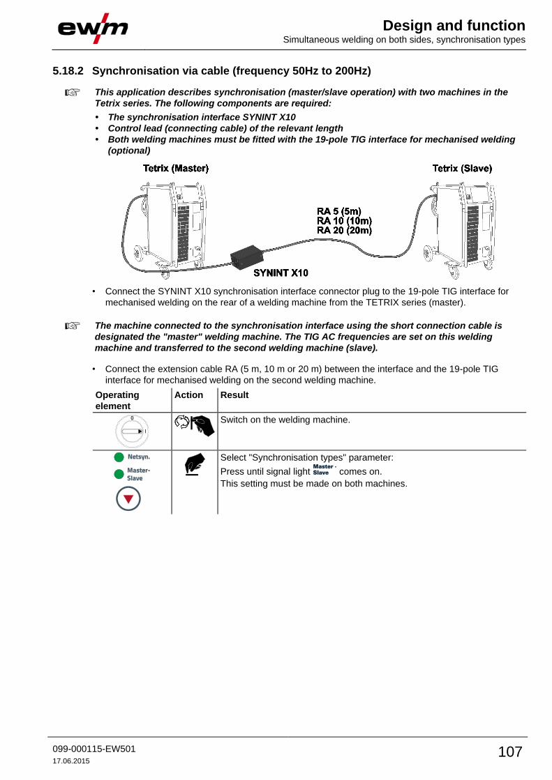
Design and function Simultaneous welding on both sides, synchronisation types
099-000115-EW501
17.06.2015 107
5.18.2 Synchronisation via cable (frequency 50Hz to 200Hz)
This application describes synchronisation (master/slave operation) with two machines in the
Tetrix series. The following components are required:
• The synchronisation interface SYNINT X10
• Control lead (connecting cable) of the relevant length
• Both welding machines must be fitted with the 19-pole TIG interface for mechanised welding
(optional)
• Connect the SYNINT X10 synchronisation interface connector plug to the 19-pole TIG interface for
mechanised welding on the rear of a welding machine from the TETRIX series (master).
The machine connected to the synchronisation interface using the short connection cable is
designated the "master" welding machine. The TIG AC frequencies are set on this welding
machine and transferred to the second welding machine (slave).
• Connect the extension cable RA (5 m, 10 m or 20 m) between the interface and the 19-pole TIG
interface for mechanised welding on the second welding machine.
Operating
element
Action Result
Switch on the welding machine.
Select "Synchronisation types" parameter:
Press until signal light comes on.
This setting must be made on both machines.

Design and function Interfaces for automation
108 099-000115-EW501
17.06.2015
5.19 Interfaces for automation
CAUTION
Damage to the machine due to improper connection!
Unsuitable control leads or incorrect connection of input and output signals can cause
damage to the machine.
• Only use shielded control leads!
• If the machine is to be operated with control voltages connection via suitable isolation
amplifiers is required!
• To control the main or secondary current via control voltages, the relevant inputs must be
enabled (see specification for activation of control voltage).
5.19.1 TIG interface for mechanised welding Pin Signal
shape
Designation Diagram
A Output PE Connection for cable screen
B Output REGaus For servicing purposes only
C Input SYN_E Synchronisation for master/slave operation
D Input
(no c.)
IGRO Current flows signal I>0 (maximum load
20mA / 15V)
0V = welding current flowing
E
+
R
Input
Output
Not/Aus Emergency stop for higher level shut-down
of the power source.
To use this function, jumper 1 must be
unplugged on PCB T320/1 in the welding
machine. Contact open welding current
off
F Output 0V Reference potential
G - NC Not assigned
H Output Uist Actual welding voltage, measured on pin F,
0-10V (0V = 0V, 10V = 100V)
J Vschweiss Reserved for special purposes
K Input SYN_A Synchronisation for master/slave operation
L Input Str/Stp Start / stop welding current, same as torch
trigger.
Only available in non-latched operating
mode. +15V = start, 0V stop
M Output +15V Voltage supply
+15V, max. 75mA
N Output -15V Voltage supply
-15V, max. 25mA
P - NC Not assigned
S Output 0V Reference potential
T Output Iist Actual welding current, measured on pin F;
0-10V (0V = 0A, 10V = 1000A)
U NC
V Output SYN_A 0V Synchronisation for master/slave operation

Design and function Interfaces for automation
099-000115-EW501
17.06.2015 109
5.19.2 Remote control connection socket, 19-pole
Figure 5-54
Pos. Pin Signal shape Designation
1 A Output Connection for cable screen (PE)
2 B/L Output Current flows signal I>0, galvanically isolated (max. +- 15V/100mA)
3 F Output Reference voltage for potentiometer 10V (max. 10mA)
4 C Input Control value specification for main current, 0-10V (0V = Imin, 10V =
Imax)
5 D Input Control value specification for secondary current, 0-10V (0V = Imin, 10V
= Imax)
6 J/U Output Reference 0V
7 K Output Power supply +15V, max. 75mA
8 V Output Power supply -15V, max. 25mA
9 R Input Start/Stop welding current
10 H Input Switching between main and secondary welding currents (pulses)
11 M/N/P Input Activation of control voltage specification
Set all 3 signals to reference potential 0V to activate external control
voltage specification for main and secondary currents
12 G Output Measured value ISETPOINT (1V = 100A)

Design and function Protecting welding parameters from unauthorised access
110 099-000115-EW501
17.06.2015
5.20 Protecting welding parameters from unauthorised access
These accessory components can be retrofitted as an option - See 9 Accessories chapter.
To protect against unauthorised or unintentional adjustment of the welding parameters on the machine,
the control input can be locked with the aid of a key switch.
Key position 1 = All parameters can be set
Key position 0 = Only the following operating elements are functional:
• “Operating mode” button
• “Welding parameter setting” rotary transducer
• “Display switching” button
• “TIG pulse welding”/“Select activArc” button
• “Select welding parameters” button
• “Gas test” button
5.21 PC interface
CAUTION
Equipment damage or faults may occur if the PC is connected incorrectly!
Not using the SECINT X10USB interface results in equipment damage or faults in signal
transmission. The PC may be destroyed due to high frequency ignition pulses.
• Interface SECINT X10USB must be connected between the PC and the welding machine!
• The connection must only be made using the cables supplied (do not use any additional
extension cables)!
Please note the relevant documentation of the accessory components.
5.22 Machine configuration menu The machine menu includes basic functions such as torch modes, display settings and the service menu.
5.22.1 Selecting, changing and saving parameters
ENTER (enter the menu)
• Switch off machine at the main switch
• Press and hold the "welding parameters" button and switch the machine on again at the same
time.
NAVIGATION (navigating in the menu)
• Parameters are selected by pressing the "welding parameters" button.
• Set or change the parameters by turning the "welding parameter setting" rotary dial.
EXIT (leave the menu)
• Select the "Elt" menu item.
• Press the "welding parameters" button (settings will be applied, machine changes to the
ready-to-operate status).

Design and function Machine configuration menu
099-000115-EW501
17.06.2015 111
EXIT
NAVIGATION
ENTER
+l
0
Figure 5-55

Design and function Machine configuration menu
112 099-000115-EW501
17.06.2015
Display Setting/selection
Exit the menu
Exit
Torch configuration menu
Set welding torch functions
Torch mode (factory setting 1)
Up-/Down speed
Increase value = rapid current change (factory setting 10)
Reduce value = slow current change
Setting the first increment
Setting: 1 to 20 (factory setting 1)
Get JOB number Set maximum selectable jobs (setting: 1 to 128, factory setting 10).
Additional parameter after activating the BLOCK JOB function.
Start JOB
Set first JOB to get (setting: 129 to 256, factory setting 129).
Machine configuration
Settings for machine functions and parameter display
Operating principle • on = synergic parameter setting (factory setting)
• off = conventional parameter setting
Welding current display (ignition, secondary, end and hotstart currents) • Pro = welding current display as a percentage of the main current (factory setting)
• Abs = absolute welding current display
Non-latched operation (C version)
• on = on
• off = off (factory setting)
Setting for the primary setpoint value display
Defines the priority display for setpoint values:
• bld = panel thickness
• vol = welding voltage (factory setting)
RINT X12, JOB control for automation solutions
• on = on
• off = off (factory setting)
Power display switching (MMA)
• on = actual value display
• off = setpoint value display (factory setting)
Pulses in the upslope and downslope phases
The function can be switched on or off
additional wire welding, operating mode • I>0 = filler wire mode for automated applications,
wire is conveyed when current flows • 2t (factory setting) to 4t = operating mode non-latched to latched
TIG antistick
• on = function active (factory setting).
• off = function inactive.
Program 0 block
With machines with key switch (access block), program 0 can be disabled. When the
access block has been enabled, programs 1–x only can be switched.
off All programs can be selected (ex works)
on Programs 1–x can be selected (program 0 disabled)

Design and function Machine configuration menu
099-000115-EW501
17.06.2015 113
Display Setting/selection
Warnings
Warnings can be issued prior to a machine failure.
off Warnings disabled (ex works)
on Warnings enabled
Machine configuration (part two)
Settings for machine functions and parameter display
Ramp function Remote control RTF 1
The ramp function can be switched on and off
Tungsten balling with RT AC remote control
off Function switched off (factory setting)
on Function switched on (in addition, the "AC Balance" rotary knob at the
RT AC remote control has to be turned to the left stop)
Tungsten balling (old variant)
• on = on
• off = off (ex works)
Welding current polarity switching
• on = polarity switching at the RT PWS 1 19POL remote control (ex works)
• off = polarity switching at the welding machine control
spotMatic
Variation of operation mode spotArc, ignition with workpiece contact
• on = on
• off = off (factory setting)
Setting spot time
• on = Short spot time (5 ms - 999 ms, 1 ms- steps)
• off = long spot time (0,01 s - 20,0 s, 10 ms- steps)
Setting process activation
• on = Separate process activation:
The welding process has to be reactivated for every arc ignition by pressing the torch
trigger.
• off = Permanent process activation:
The welding process is activated by pressing the torch trigger once. The following arc
ignitions are initiated by shortly touching the tungsten electrode against the
workpiece.
Torch cooling mode • AUt = automatic operation (ex works) • on = permanently switched on
• off = permanently switched off
Welding torch cooling system pre-flow time
Setting 1–60 min. (ex works 5)
Time-based power-saving mode
• 5 min.–60 min. = Time to activation of power-saving mode in case of inactivity.
• off = inactivated (ex works 20 min.)
Expert menu
AC mean value controller
• on = on (factory setting)
• off = off
Switching option for welding current potential (dc+) with TIG DC
• off = Select option for TIG DC+ is blocked (factory setting). Serves to protect the
tungsten electrode from being destroyed.
• on = Polarity can be selected freely
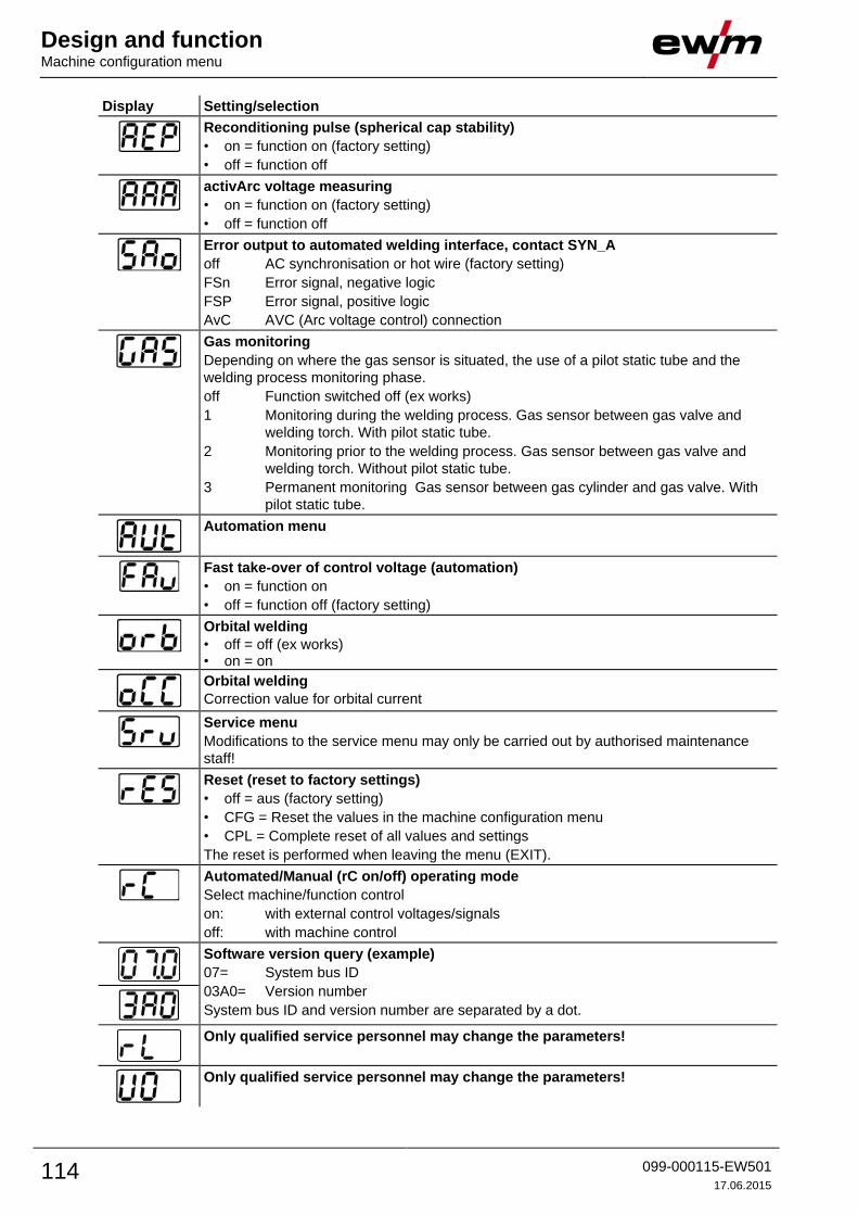
Design and function Machine configuration menu
114 099-000115-EW501
17.06.2015
Display Setting/selection
Reconditioning pulse (spherical cap stability)
• on = function on (factory setting)
• off = function off
activArc voltage measuring
• on = function on (factory setting)
• off = function off
Error output to automated welding interface, contact SYN_A
off AC synchronisation or hot wire (factory setting)
FSn Error signal, negative logic
FSP Error signal, positive logic
AvC AVC (Arc voltage control) connection
Gas monitoring
Depending on where the gas sensor is situated, the use of a pilot static tube and the
welding process monitoring phase.
off Function switched off (ex works)
1 Monitoring during the welding process. Gas sensor between gas valve and
welding torch. With pilot static tube.
2 Monitoring prior to the welding process. Gas sensor between gas valve and
welding torch. Without pilot static tube.
3 Permanent monitoring Gas sensor between gas cylinder and gas valve. With
pilot static tube.
Automation menu
Fast take-over of control voltage (automation)
• on = function on
• off = function off (factory setting)
Orbital welding
• off = off (ex works) • on = on
Orbital welding
Correction value for orbital current
Service menu
Modifications to the service menu may only be carried out by authorised maintenance
staff!
Reset (reset to factory settings)
• off = aus (factory setting)
• CFG = Reset the values in the machine configuration menu
• CPL = Complete reset of all values and settings
The reset is performed when leaving the menu (EXIT).
Automated/Manual (rC on/off) operating mode
Select machine/function control
on: with external control voltages/signals
off: with machine control
Software version query (example)
07= System bus ID
03A0= Version number
System bus ID and version number are separated by a dot.
Only qualified service personnel may change the parameters!
Only qualified service personnel may change the parameters!

Design and function Machine configuration menu
099-000115-EW501
17.06.2015 115
Display Setting/selection
Ignition pulse limit
Setting 0 ms–15 ms (increments of 1 ms)

Design and function Machine configuration menu
116 099-000115-EW501
17.06.2015
5.22.2 Aligning the cable resistance To ensure optimum welding properties, the electric cable resistance should be aligned again whenever an
accessory component such as the welding torch or the intermediate hose package (AW) has been
changed. The resistance value of the cables can be set directly or can be aligned by the power source. In
the delivery state the cable resistance is set to the optimum values. To optimise the welding properties for
other cable lengths, an alignment process (voltage correction) is necessary.
2
3
4
1
l
0
l
0
+
+Te
trix
C
las
sic
Te
trix
S
ma
rt
C
om
fort
S
yn
erg
ic
B
A
Figure 5-56

Design and function Machine configuration menu
099-000115-EW501
17.06.2015 117
1 Preparation
• Switch off the welding machine.
• Unscrew the gas nozzle from the welding torch.
• Unfasten the tungsten electrode and extract.
2 Configuration
• Press the or (Tetrix Classic) push-button while simultaneously switching on the welding
machine.
• Release push-button.
• The required parameter can now be selected using the rotary knob.
3 Adjustment/measurement
• Applying slight pressure, press the welding torch with the collet against a clean, purged location on the
workpiece and then press the torch trigger for approx. 2 seconds. A short-circuit current will flow
briefly, which is used to determine and display the cable resistance. The value can be between 0 mΩ
and 60 mΩ. The new value is immediately saved without requiring further confirmation. If no value is
shown on the right-hand display, then measurement failed. The measurement must be repeated.
4 Restoring welding standby mode
• Switch off the welding machine.
• Lock the tungsten electrode in the collet again.
• Screw the gas nozzle onto the welding torch.
• Switch on the welding machine
5.22.3 Power-saving mode (Standby) The power-saving function can be activated either by pressing the button for a longer time - See 4.8
Machine control – Operating elements chapter or by setting a parameter in the configuration menu (time-
based power-saving mode).
When power-saving mode is activated, both machine displays show the horizontal digit in the
centre of the display only.
Pressing any operating element (e.g. tapping the torch trigger) deactivates power-saving mode and the
machine is ready for welding again.

Maintenance, care and disposal Maintenance work
118 099-000115-EW501
17.06.2015
6 Maintenance, care and disposal
DANGER
Do not carry out any unauthorised repairs or modifications!
To avoid injury and equipment damage, the unit must only be repaired or modified by
specialist, skilled persons!
The warranty becomes null and void in the event of unauthorised interference.
• Appoint only skilled persons for repair work (trained service personnel)!
Risk of injury from electric shock!
Cleaning machines that are not disconnected from the mains can lead to serious
injuries!
• Disconnect the machine completely from the mains.
• Remove the mains plug!
• Wait for 4 minutes until the capacitors have discharged!
6.1 Maintenance work Repair and maintenance work may only be performed by qualified authorised personnel; otherwise the
right to claim under warranty is void. In all service matters, always consult the dealer who supplied the
machine. Return deliveries of defective equipment subject to warranty may only be made through your
dealer. When replacing parts, use only original spare parts. When ordering spare parts, please quote the
machine type, serial number and item number of the machine, as well as the type designation and item
number of the spare part.
6.2 General When used in the specified environmental conditions and under normal operating conditions, this
machine is largely maintenance-free and requires a minimum of care.
There are some points, which should be observed, to guarantee fault-free operation of your welding
machine. Among these are regular cleaning and checking as described below, depending on the pollution
level of the environment and the length of time the unit is in use.
6.3 Maintenance work, intervals 6.3.1 Daily maintenance tasks
6.3.1.1 Visual inspection
• Mains supply lead and its strain relief
• Check the wearing parts in the torch.
• Check torch, hose package and power connections for exterior damage and replace or have repaired
by specialist staff as necessary!
• Other, general condition
6.3.1.2 Functional test
• Operating, message, safety and adjustment devices (Functional test)
• Check correct mounting of the wire spool.
• Purge the wire guide from the direction of the Euro torch connector with oil- and condensate-free
compressed air or shielding gas.
• Welding current cables (check that they are fitted correctly and secured)
• Gas tubes and their switching equipment (solenoid valve)
• Gas cylinder securing elements

Maintenance, care and disposal Maintenance work, intervals
099-000115-EW501
17.06.2015 119
6.3.2 Monthly maintenance tasks
6.3.2.1 Visual inspection
• Casing damage (front, rear and side walls)
• Wheels and their securing elements
• Transport elements (strap, lifting lugs, handle)
6.3.2.2 Functional test
• Selector switches, command devices, emergency stop devices, voltage reducing devices, message
and control lamps
• Check coolant tubes and their connections for impurities
• Check that the wire guide elements (inlet nipple, wire guide tube) are fitted securely.
• Check that all connections and wearing parts are hand-tight and tighten if necessary.
• Check the wire guide.
• Check and clean the welding torch. Deposits in the torch can cause short circuits and have a negative
impact on the welding result, ultimately causing damage to the torch.
• Check that all screw and plug connections and replaceable parts are secured correctly, tighten if
necessary.
6.3.3 Annual test (inspection and testing during operation)
The welding machine may only be tested by competent, capable personsl. A capable person is
one who, because of his training, knowledge and experience, is able to recognise the dangers
that can occur while testing welding power sources as well as possible subsequent damage and
who is able to implement the required safety procedures.
For more information refer to the "Warranty registration" brochure supplied and our information
regarding warranty, maintenance and testing at www.ewm-group.com!
A periodic test according to IEC 60974-4 "Periodic inspection and test" has to be carried out. In addition
to the regulations on testing given here, the relevant local laws and regulations must also be observed.

Maintenance, care and disposal Disposing of equipment
120 099-000115-EW501
17.06.2015
6.4 Disposing of equipment
Proper disposal!
The machine contains valuable raw materials, which should be recycled, and electronic
components, which must be disposed of.
• Do not dispose of in household waste!
• Observe the local regulations regarding disposal!
6.4.1 Manufacturer's declaration to the end user • According to European provisions (guideline 2002/96/EG of the European Parliament and the Council
of January, 27th 2003), used electric and electronic equipment may no longer be placed in unsorted
municipal waste. It must be collected separately. The symbol depicting a waste container on wheels
indicates that the equipment must be collected separately.
This machine is to be placed for disposal or recycling in the waste separation systems provided for
this purpose.
• According to German law (law governing the distribution, taking back and environmentally correct
disposal of electric and electronic equipment (ElektroG) from 16.03.2005), used machines are to be
placed in a collection system separate from unsorted municipal waste. The public waste management
utilities (communities) have created collection points at which used equipment from private
households can be disposed of free of charge.
• Information about giving back used equipment or about collections can be obtained from the
respective municipal administration office.
• EWM participates in an approved waste disposal and recycling system and is registered in the Used
Electrical Equipment Register (EAR) under number WEEE DE 57686922.
• In addition to this, returns are also possible throughout Europe via EWM sales partners.
6.5 Meeting the requirements of RoHS We, EWM AG Mündersbach, hereby confirm that all products supplied by us which are affected by the
RoHS Directive, meet the requirements of the RoHS (Directive 2011/65/EU).

Rectifying faults Checklist for rectifying faults
099-000115-EW501
17.06.2015 121
7 Rectifying faults All products are subject to rigorous production checks and final checks. If, despite this, something fails to
work at any time, please check the product using the following flowchart. If none of the fault rectification
procedures described leads to the correct functioning of the product, please inform your authorised
dealer.
7.1 Checklist for rectifying faults
The correct machine equipment for the material and process gas in use is a fundamental
requirement for perfect operation!
Legend Symbol Description
Fault/Cause
Remedy
Coolant error/no coolant flowing
Insufficient coolant flow
Check coolant level and refill if necessary
Eliminate kinks in conduit system (hose packages)
Reset automatic cutout of the coolant pump by activating
Air in the coolant circuit
Vent coolant circuit
Functional errors
Machine control without displaying the signal lights after switching on
Phase failure > check mains connection (fuses)
No welding performance
Phase failure > check mains connection (fuses)
Various parameters cannot be set
Entry level is blocked, disable access lock - See 5.20 Protecting welding parameters from
unauthorised access chapter
Connection problems
Make control lead connections and check that they are fitted correctly.
Welding torch overheated
Loose welding current connections
Tighten power connections on the torch and/or on the workpiece
Tighten contact tip correctly
Overload
Check and correct welding current setting
Use a more powerful welding torch
Unstable arc
Unsuitable or worn welding torch equipment
Adjust contact tip to wire diameter and -material and replace if necessary
Adjust wire guide to material in use, blow through and replace if necessary
Material inclusions in the tungsten electrode due to contact with filler material or workpiece
Regrind or replace the tungsten electrode
Incompatible parameter settings
Check settings and correct if necessary

Rectifying faults Checklist for rectifying faults
122 099-000115-EW501
17.06.2015
Wire feed problems
Unsuitable or worn welding torch equipment
Adjust contact tip (cold wire/hot wire) to wire diameter, blow through and replace if necessary
Adjust wire guide to material in use, blow through and replace if necessary
Contact tip blocked
Clean, spray with anti-spatter spray and replace if necessary
Worn wire rolls
Check and replace if necessary
Wire feed motor without supply voltage (automatic cutout triggered by overloading)
Reset triggered fuse (rear of the power source) by pressing the key button
Kinked hose packages
Extend and lay out the torch hose package
Incompatible parameter settings
Check settings and correct if necessary
Arc between gas nozzle and workpiece (metal vapour on the gas nozzle)
Replace gas nozzle
Pore formation
Inadequate or missing gas shielding
Check shielding gas setting and replace shielding gas cylinder if necessary
Shield welding site with protective screens (draughts affect the welding result)
Use gas lens for aluminium applications and high-alloy steels
Unsuitable or worn welding torch equipment
Check size of gas nozzle and replace if necessary
Condensation (hydrogen) in the gas tube
Purge hose package with gas or replace

Rectifying faults Warnings (power source)
099-000115-EW501
17.06.2015 123
7.2 Warnings (power source)
A warning is denoted by the letter A on the machine display, or Att in case of multiple machine
displays. The possible cause of the warning is signalled by the respective error code (see table).
The display of possible error numbers depends on the machine version (interfaces/functions).
• If multiple errors occur, these are displayed in succession.
• Document machine errors and inform service staff as necessary.
Warning code Possible cause Remedy
1 Machine excess temperature Allow the machine to cool down
2 Half-wave failures Check process parameters
3 Welding torch cooling warning Check coolant level and refill if necessary
4 Gas warning Check gas supply
5 See warning number 3 -
6 Welding consumable (wire electrode)
fault
Check wire feeding (with machines with filler
wire)
7 CAN bus failure Inform service
32 Encoder malfunction, drive Inform service
33 Drive is operating under overload
conditions
Adjust mechanical load
34 Unknown JOB Select alternative JOB
The warnings can be reset by pressing a push-button (see table):
Welding machine control Smart Classic Comfort Synergic
push-button

Rectifying faults Error messages (power source)
124 099-000115-EW501
17.06.2015
7.3 Error messages (power source)
A welding machine error is indicated by the collective fault signal lamp (A1) lighting up and an
error code (see table) being displayed in the machine control display. In the event of a machine
error, the power unit shuts down.
The display of possible error numbers depends on the machine version (interfaces/functions).
• If multiple errors occur, these are displayed in succession.
• Document machine errors and inform service staff as necessary.
Error message Possible cause Remedy
Err 3 Speedometer error Check wire guide/hose package
Wire feeder is not connected • Switch off cold wire mode in the device
configuration menu (off status)
• Connect the wire feeder
Err 4 Temperature error Allow the machine to cool down
Error in emergency stop circuit
(interface for automated welding)
• Check the external interrupt equipment
• Check jumper JP 1 on PCB T320/1
Err 5 Overvoltage Switch off machine and check the mains
voltage Err 6 Low voltage
Err 7 Coolant error (with connected cooling
unit only)
Check coolant level and refill if necessary
Err 8 Gas error Check gas supply
Err 9 Secondary overvoltage Switch machine off and on again,
inform the service department if the error
continues Err 10 PE error
Err 11 FastStop position Edge 'Acknowledge error' signal (0 to 1) via
robot interface (if available)
Err 12 VRD error Switch the machine off and on again.
If the error persists, inform the service dept.
Err 16 Pilot arc current Check welding torch
Err 17 Cold wire error
Excess current limit of a motor control
card has been triggered
Cold wire error – a permanent deviation
between wire nominal value and actual
value or a blocked drive has been
detected in the process
Inspect the wire feed system (drives, tube
packages, torch):
• Check cold wire on the torch / work piece
(moved against work piece?)
• Check relation of process wire feed
speed to robot travel speed, and correct
if necessary
• Check wire feed for stiffness with wire
inching function (resolve by checking
wire guides section by section)
Reset error via robot interface (reset error)
Err 18 Plasma gas error
Nominal value significantly different
from actual value -> No plasma gas?
• Check plasma gas supply; use the
plasma gas test function on "cold wire
feed unit" if necessary
• Check guiding / connections of the gas
supply hose for leaks / kinks
• Check that the gas supply lead of the
plasma torch is not blocked
Reset error via robot interface (reset error)
Err 19 Shielding gas
Nominal value significantly different
from actual value -> No shielding gas?
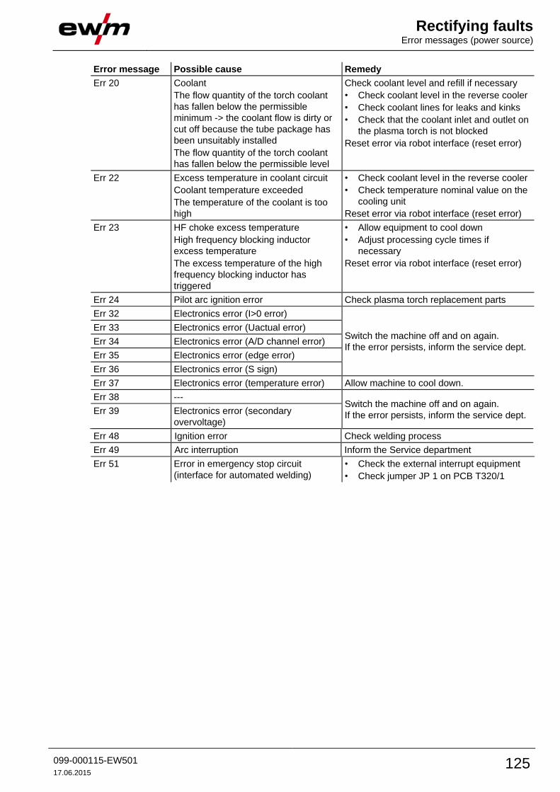
Rectifying faults Error messages (power source)
099-000115-EW501
17.06.2015 125
Error message Possible cause Remedy
Err 20 Coolant
The flow quantity of the torch coolant
has fallen below the permissible
minimum -> the coolant flow is dirty or
cut off because the tube package has
been unsuitably installed
The flow quantity of the torch coolant
has fallen below the permissible level
Check coolant level and refill if necessary
• Check coolant level in the reverse cooler
• Check coolant lines for leaks and kinks
• Check that the coolant inlet and outlet on
the plasma torch is not blocked
Reset error via robot interface (reset error)
Err 22 Excess temperature in coolant circuit
Coolant temperature exceeded
The temperature of the coolant is too
high
• Check coolant level in the reverse cooler
• Check temperature nominal value on the
cooling unit
Reset error via robot interface (reset error)
Err 23 HF choke excess temperature
High frequency blocking inductor
excess temperature
The excess temperature of the high
frequency blocking inductor has
triggered
• Allow equipment to cool down
• Adjust processing cycle times if
necessary
Reset error via robot interface (reset error)
Err 24 Pilot arc ignition error Check plasma torch replacement parts
Err 32 Electronics error (I>0 error)
Switch the machine off and on again.
If the error persists, inform the service dept.
Err 33 Electronics error (Uactual error)
Err 34 Electronics error (A/D channel error)
Err 35 Electronics error (edge error)
Err 36 Electronics error (S sign)
Err 37 Electronics error (temperature error) Allow machine to cool down.
Err 38 --- Switch the machine off and on again.
If the error persists, inform the service dept. Err 39 Electronics error (secondary
overvoltage)
Err 48 Ignition error Check welding process
Err 49 Arc interruption Inform the Service department
Err 51 Error in emergency stop circuit
(interface for automated welding)
• Check the external interrupt equipment
• Check jumper JP 1 on PCB T320/1

Rectifying faults Resetting welding parameters to the factory settings
126 099-000115-EW501
17.06.2015
7.4 Resetting welding parameters to the factory settings
All customised welding parameters that are stored will be replaced by the factory settings.
ENTER
+
EXIT NAVIGATION
l
0
Figure 7-1
Display Setting/selection
Exit the menu
Exit
Service menu
Modifications to the service menu may only be carried out by authorised maintenance
staff!
Reset (reset to factory settings)
• off = aus (factory setting)
• CFG = Reset the values in the machine configuration menu
• CPL = Complete reset of all values and settings
The reset is performed when leaving the menu (EXIT).
Switch off
Switching off machine function
Reset machine configuration
Resetting the values in the machine configuration menu
Complete reset
Complete reset of all values and settings by the factory settings
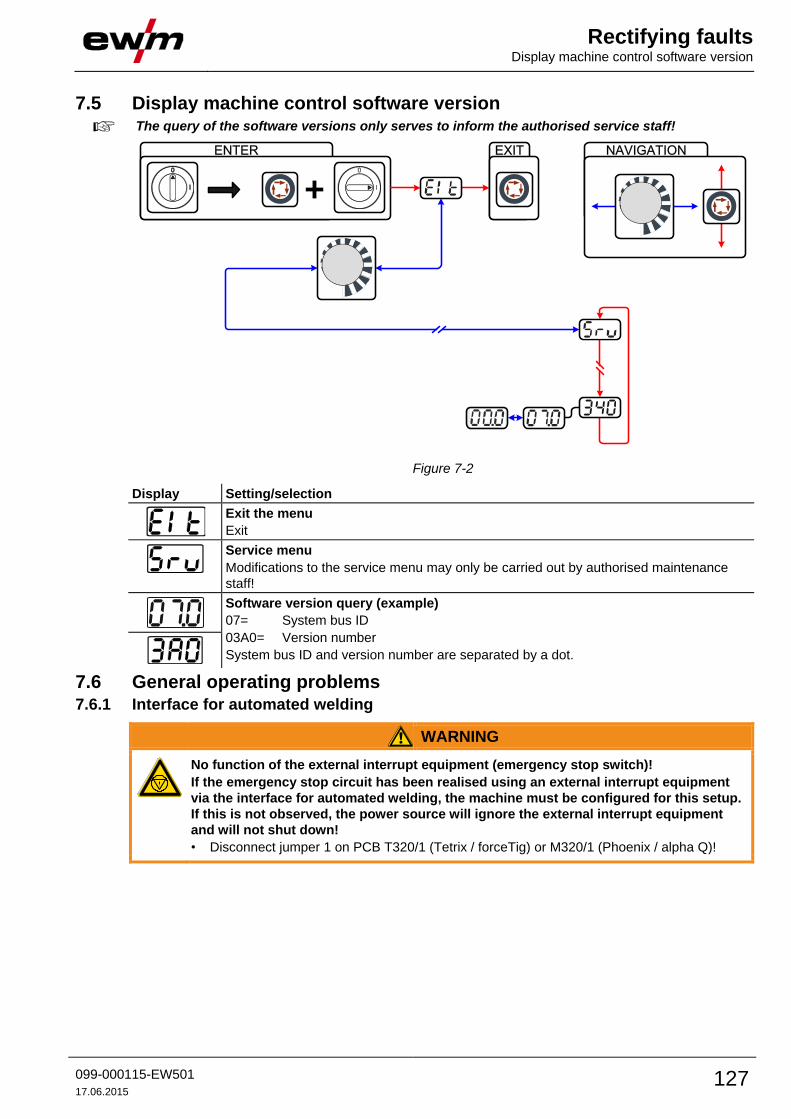
Rectifying faults Display machine control software version
099-000115-EW501
17.06.2015 127
7.5 Display machine control software version
The query of the software versions only serves to inform the authorised service staff!
ENTER
+
EXIT NAVIGATION
l
0
Figure 7-2
Display Setting/selection
Exit the menu
Exit
Service menu
Modifications to the service menu may only be carried out by authorised maintenance
staff!
Software version query (example)
07= System bus ID
03A0= Version number
System bus ID and version number are separated by a dot.
7.6 General operating problems 7.6.1 Interface for automated welding
WARNING
No function of the external interrupt equipment (emergency stop switch)!
If the emergency stop circuit has been realised using an external interrupt equipment
via the interface for automated welding, the machine must be configured for this setup.
If this is not observed, the power source will ignore the external interrupt equipment
and will not shut down!
• Disconnect jumper 1 on PCB T320/1 (Tetrix / forceTig) or M320/1 (Phoenix / alpha Q)!

Rectifying faults Vent coolant circuit
128 099-000115-EW501
17.06.2015
7.7 Vent coolant circuit
Coolant tank and quick connect coupling of coolant supply and return are only fitted in machines
with water cooling.
To vent the cooling system always use the blue coolant connection, which is located as deep as
possible inside the system (close to the coolant tank)!
Figure 7-3
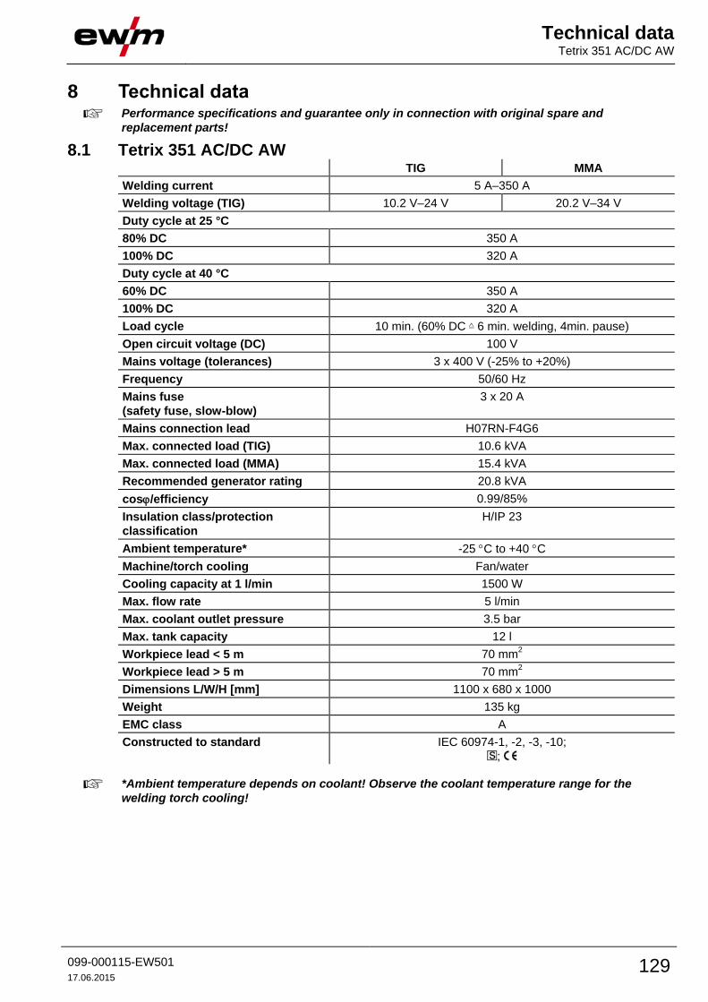
Technical data Tetrix 351 AC/DC AW
099-000115-EW501
17.06.2015 129
8 Technical data Performance specifications and guarantee only in connection with original spare and
replacement parts!
8.1 Tetrix 351 AC/DC AW TIG MMA
Welding current 5 A–350 A
Welding voltage (TIG) 10.2 V–24 V 20.2 V–34 V
Duty cycle at 25 °C
80% DC 350 A
100% DC 320 A
Duty cycle at 40 °C
60% DC 350 A
100% DC 320 A
Load cycle 10 min. (60% DC 6 min. welding, 4min. pause)
Open circuit voltage (DC) 100 V
Mains voltage (tolerances) 3 x 400 V (-25% to +20%)
Frequency 50/60 Hz
Mains fuse
(safety fuse, slow-blow)
3 x 20 A
Mains connection lead H07RN-F4G6
Max. connected load (TIG) 10.6 kVA
Max. connected load (MMA) 15.4 kVA
Recommended generator rating 20.8 kVA
cos/efficiency 0.99/85%
Insulation class/protection
classification
H/IP 23
Ambient temperature* -25 C to +40 C
Machine/torch cooling Fan/water
Cooling capacity at 1 l/min 1500 W
Max. flow rate 5 l/min
Max. coolant outlet pressure 3.5 bar
Max. tank capacity 12 l
Workpiece lead < 5 m 70 mm2
Workpiece lead > 5 m 70 mm2
Dimensions L/W/H [mm] 1100 x 680 x 1000
Weight 135 kg
EMC class A
Constructed to standard IEC 60974-1, -2, -3, -10;
;
*Ambient temperature depends on coolant! Observe the coolant temperature range for the
welding torch cooling!

Technical data Tetrix 451 AC/DC AW
130 099-000115-EW501
17.06.2015
8.2 Tetrix 451 AC/DC AW TIG MMA
Welding current 5 A–450 A
Welding voltage 10.2 V–28.0 V 20.2 V–38.0 V
Duty cycle at 25 °C
100% DC 450 A
Duty cycle at 40 °C
80% DC 450 A
100% DC 420 A
Load cycle 10 min. (60% DC 6 min. welding, 4min. pause)
Open circuit voltage (DC) 79 V
Mains voltage (tolerances) 3 x 400 V (-25% to +20%)
Frequency 50/60 Hz
Mains fuse
(safety fuse, slow-blow)
3 x 32 A
Mains connection lead H07RN-F4G6
Max. connected load (TIG) 16.3 kVA
Max. connected load (MMA) 22.0 kVA
Recommended generator rating 29.7 kVA
cos/efficiency 0.99/85%
Insulation class/protection
classification
H/IP 23
Ambient temperature* -25 C to +40 C
Machine/torch cooling Fan/water
Cooling capacity at 1 l/min 1500 W
Max. flow rate 5 l/min
Max. coolant outlet pressure 3.5 bar
Max. tank capacity 12 l
Workpiece lead < 5 m 70 mm2
Workpiece lead > 5 m 95 mm2
Dimensions L/W/H [mm] 1080 x 690 x 1195
Weight 184.5 kg
EMC class A
Constructed to standard IEC 60974-1, -2, -3, -10;
;
*Ambient temperature depends on coolant! Observe the coolant temperature range for the
welding torch cooling!
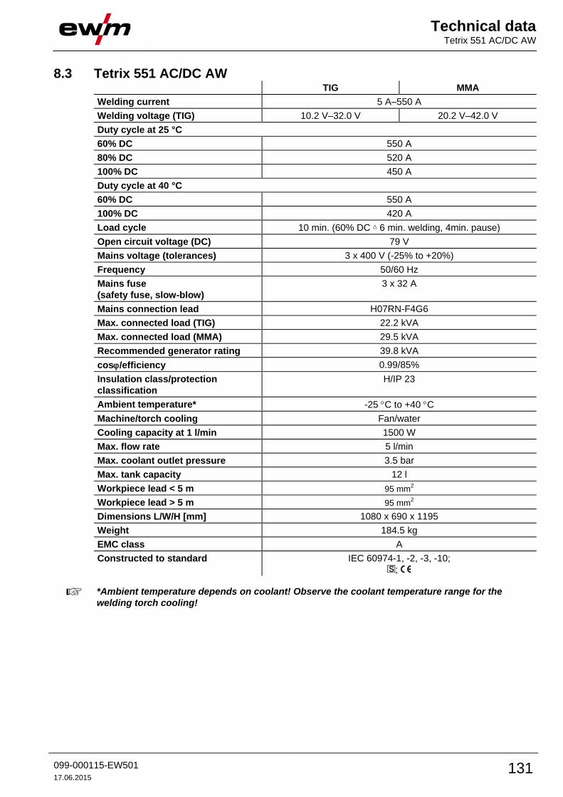
Technical data Tetrix 551 AC/DC AW
099-000115-EW501
17.06.2015 131
8.3 Tetrix 551 AC/DC AW TIG MMA
Welding current 5 A–550 A
Welding voltage (TIG) 10.2 V–32.0 V 20.2 V–42.0 V
Duty cycle at 25 °C
60% DC 550 A
80% DC 520 A
100% DC 450 A
Duty cycle at 40 °C
60% DC 550 A
100% DC 420 A
Load cycle 10 min. (60% DC 6 min. welding, 4min. pause)
Open circuit voltage (DC) 79 V
Mains voltage (tolerances) 3 x 400 V (-25% to +20%)
Frequency 50/60 Hz
Mains fuse
(safety fuse, slow-blow)
3 x 32 A
Mains connection lead H07RN-F4G6
Max. connected load (TIG) 22.2 kVA
Max. connected load (MMA) 29.5 kVA
Recommended generator rating 39.8 kVA
cos/efficiency 0.99/85%
Insulation class/protection
classification
H/IP 23
Ambient temperature* -25 C to +40 C
Machine/torch cooling Fan/water
Cooling capacity at 1 l/min 1500 W
Max. flow rate 5 l/min
Max. coolant outlet pressure 3.5 bar
Max. tank capacity 12 l
Workpiece lead < 5 m 95 mm2
Workpiece lead > 5 m 95 mm2
Dimensions L/W/H [mm] 1080 x 690 x 1195
Weight 184.5 kg
EMC class A
Constructed to standard IEC 60974-1, -2, -3, -10;
;
*Ambient temperature depends on coolant! Observe the coolant temperature range for the
welding torch cooling!
Accessories System components
132 099-000115-EW501
17.06.2015
9 Accessories Performance-dependent accessories like torches, workpiece leads, electrode holders or
intermediate hose packages are available from your authorised dealer.
9.1 System components Type Designation Item no.
Tetrix drive 4L TIG wire feed unit, cooling water conduit 090-000094-00502
Tetrix 270 Hotwire TIG constant power source to pre-heat the wire, 5–
270 A, portable, incl. connection cable
090-000164-00502
ON TB drive 4L / HW Transport bracket for Tetrix drive 4L and Tetrix 270
Hotwire
092-000038-00000
9.2 Options 9.2.1 Tetrix 351 AC/DC
Type Designation Item no.
ON Filter T/P Retrofit option contamination filter for air inlet 092-002092-00000
ON Holder Gas Bottle <50L Holding plate for gas cylinders smaller than 50 litres 092-002151-00000
9.2.2 Tetrix 451, 551 AC/DC Type Designation Item no.
ON Filter Tetrix XL Retrofit option, dirt filter for air inlet 092-004999-00000
ON Holder Gas Bottle <50L
TETRIX XL
Optional retrofit holding plate for gas cylinder <50l 092-002345-00000
9.2.3 Tetrix 351, 451, 551 AC/DC Type Designation Item no.
ON 7pol Optional 7-pole retrofit connection socket
Accessory components and digital interfaces
092-001826-00000
ON 12pol Retox Tetrix
300/400/401/351/451/551
Optional 12-pole retrofit connection socket 092-001807-00000
ON Hose/FR Mount Optional holder for tubes and remote control for
machines without pivot support
092-002116-00000
ON LB Wheels 160x40MM Retrofit option for locking brake for machine wheels 092-002110-00000
ON Tool Box Retrofit option tool box 092-002138-00000
ON Key Switch Optional retrofit kit for key switch 092-001828-00000
Accessories General accessories
099-000115-EW501
17.06.2015 133
9.3 General accessories Type Designation Item no.
KF 23E-10 Coolant (-10 °C), 9.3 l 094-000530-00000
KF 23E-200 Coolant (-10 °C), 200 litres 094-000530-00001
KF 37E-10 Coolant (-20 °C), 9.3 l 094-006256-00000
KF 37E-200 Coolant (-20 °C), 200 l 094-006256-00001
TYP 1 Frost protection tester 094-014499-00000
DMDIN TN 200B AR/MIX 35L Manometer pressure regulator 094-000009-00000
GH 2X1/4'' 2M Gas hose 094-000010-00001
5POLE/CEE/32A/M Machine plug 094-000207-00000
HOSE BRIDGE UNI Tube bridge 092-007843-00000
9.4 Remote controls and accessories Type Designation Item no.
RTF1 19POL 5 M Foot-operated remote control current with
connection cable
094-006680-00000
RTF2 19POL 5 M Foot-operated remote control current with
connection cable
090-008764-00000
RT1 19POL Remote control current 090-008097-00000
RTG1 19POL Remote control, current 090-008106-00000
RTAC1 19POL Remote control current/balance/frequency 090-008197-00000
RT PWS1 19POL Remote control vertical-down current, pole reversal 090-008199-00000
RTP1 19POL Remote control spot welding / pulses 090-008098-00000
RTP2 19POL Remote control spot welding / pulses 090-008099-00000
RTP3 spotArc 19POL spotArc remote control for spot welding / pulses 090-008211-00000
RA5 19POL 5M Remote control e.g. connection cable 092-001470-00005
RA10 19POL 10M Remote control e.g. connection cable 092-001470-00010
RA20 19POL 20M Remote control e.g. connection cable 092-001470-00020
RV5M19 19POLE 5M Extension cable 092-000857-00000
9.5 Computer communication Type Designation Item no.
PC300.Net PC300.Net welding parameter software kit incl.
cable and SECINT X10 USB interface
090-008777-00000

Appendix A JOB-List
134 099-000115-EW501
17.06.2015
10 Appendix A 10.1 JOB-List
JO
B
Process Material Wire Seam position
Tu
ng
ste
n e
lec
tro
de
TIG
TIG
ho
t w
ire
TIG
co
ld w
ire
MM
A
Fille
t w
eld
Bu
tt jo
int
Fille
t w
eld
la
p jo
int
Ve
rtic
al-
do
wn
we
ld
0,6
0,8
1,0
1,2
1,6
1 Reserved
2 CrNi/ Fe/ St 1
3 CrNi/ Fe/ St 1.6
4 CrNi/ Fe/ St 2
5 CrNi/ Fe/ St 2.4
6 CrNi/ Fe/ St 3.2
7 CrNi/ Fe/ St >3.2
8 CrNi/ Fe/ St 1
9 CrNi/ Fe/ St 1.6
10 CrNi/ Fe/ St 2
11 CrNi/ Fe/ St 2.4
12 CrNi/ Fe/ St 3.2
13 CrNi/ Fe/ St >3.2
14 CrNi/ Fe/ St 1
15 CrNi/ Fe/ St 1.6
16 CrNi/ Fe/ St 2
17 CrNi/ Fe/ St 2.4
18 CrNi/ Fe/ St 3.2
19 CrNi/ Fe/ St >3.2
20 CrNi/ Fe/ St 1
21 CrNi/ Fe/ St 1.6
22 CrNi/ Fe/ St 2
23 CrNi/ Fe/ St 2.4
24 CrNi/ Fe/ St 3.2
25 CrNi/ Fe/ St >3.2
26 Cu/CuZn 1
27 Cu/CuZn 1.6
28 Cu/CuZn 2
29 Cu/CuZn 2.4
30 Cu/CuZn 3.2
31 Cu/CuZn >3.2
32 Cu/CuZn 1
33 Cu/CuZn 1.6
34 Cu/CuZn 2
35 Cu/CuZn 2.4

Appendix A JOB-List
099-000115-EW501
17.06.2015 135
JO
B
Process Material Wire Seam position
Tu
ng
ste
n e
lec
tro
de
TIG
TIG
ho
t w
ire
TIG
co
ld w
ire
MM
A
Fille
t w
eld
Bu
tt jo
int
Fille
t w
eld
la
p jo
int
Ve
rtic
al-
do
wn
we
ld
0,6
0,8
1,0
1,2
1,6
36 Cu/CuZn 3.2
37 Cu/CuZn >3.2
38 Cu/CuZn 1
39 Cu/CuZn 1.6
40 Cu/CuZn 2
41 Cu/CuZn 2.4
42 Cu/CuZn 3.2
43 Cu/CuZn >3.2
44 Cu/CuZn 1
45 Cu/CuZn 1.6
46 Cu/CuZn 2
47 Cu/CuZn 2.4
48 Cu/CuZn 3.2
49 Cu/CuZn >3.2
50 AlMg 1
51 AlMg 1.6
52 AlMg 2
53 AlMg 2.4
54 AlMg 3.2
55 AlMg >3.2
56 AlMg 1
57 AlMg 1.6
58 AlMg 2
59 AlMg 2.4
60 AlMg 3.2
61 AlMg >3.2
62 AlMg 1
63 AlMg 1.6
64 AlMg 2
65 AlMg 2.4
66 AlMg 3.2
67 AlMg >3.2
68 AlMg 1
69 AlMg 1.6
70 AlMg 2
71 AlMg 2.4
72 AlMg 3.2
73 AlMg >3.2

Appendix A JOB-List
136 099-000115-EW501
17.06.2015
JO
B
Process Material Wire Seam position
Tu
ng
ste
n e
lec
tro
de
TIG
TIG
ho
t w
ire
TIG
co
ld w
ire
MM
A
Fille
t w
eld
Bu
tt jo
int
Fille
t w
eld
la
p jo
int
Ve
rtic
al-
do
wn
we
ld
0,6
0,8
1,0
1,2
1,6
74 AlSi 1
75 AlSi 1.6
76 AlSi 2
77 AlSi 2.4
78 AlSi 3.2
79 AlSi >3.2
80 AlSi 1
81 AlSi 1.6
82 AlSi 2
83 AlSi 2.4
84 AlSi 3.2
85 AlSi >3.2
86 AlSi 1
87 AlSi 1.6
88 AlSi 2
89 AlSi 2.4
90 AlSi 3.2
91 AlSi >3.2
92 AlSi 1
93 AlSi 1.6
94 AlSi 2
95 AlSi 2.4
96 AlSi 3.2
97 AlSi >3.2
98 Al99 1
99 Al99 1.6
100 Al99 2
101 Al99 2.4
102 Al99 3.2
103 Al99 >3.2
104 Al99 1
105 Al99 1.6
106 Al99 2
107 Al99 2.4
108 Al99 3.2
109 Al99 >3.2
110 Al99 1
111 Al99 1.6

Appendix A JOB-List
099-000115-EW501
17.06.2015 137
JO
B
Process Material Wire Seam position
Tu
ng
ste
n e
lec
tro
de
TIG
TIG
ho
t w
ire
TIG
co
ld w
ire
MM
A
Fille
t w
eld
Bu
tt jo
int
Fille
t w
eld
la
p jo
int
Ve
rtic
al-
do
wn
we
ld
0,6
0,8
1,0
1,2
1,6
112 Al99 2
113 Al99 2.4
114 Al99 3.2
115 Al99 >3.2
116 Al99 1
117 Al99 1.6
118 Al99 2
119 Al99 2.4
120 Al99 3.2
121 Al99 >3.2
122 TIG manual/TIG classic
123 Classic electrode
124 Reserved
125 Reserved
126 Reserved
127 Electrode JOB
128 Reserved
129-179 Free JOBs or SCO (e.g. plasma)
180 CrNi/FeSt 2.4
181 CrNi/FeSt 3.2
182 CrNi/FeSt >3.2
183 CuSi 2.4
184 CuSi 3.2
185-207 Free JOBs or special customer order (SCO)/TIG Comfort (with Smart
200 only)
208-215 Free JOBs or special customer order (SCO)/electrode Comfort (with
Smart 208 only)
216-254 Free JOBs or special customer order (SCO)
255 DC- with DC+ ignition
256 Test job: 5 A to Imax
not possible
possible

Appendix B Overview of EWM branches
138 099-000115-EW501
17.06.2015
11 Appendix B 11.1 Overview of EWM branches