tests report nº 90.8106.0–in–ct–09/ 17 e Área de acÚstica · 2015. 6. 5. · akustika...
TRANSCRIPT

Page 1 of 15 (+2 Annexes)
4 / L E 4 5 6
Tests Report Nº 90.8106.0–IN–CT–09/ 17 E
Laboratory measurements of sound insulation
TEST SPECIMEN: Reinforced concrete floating slab, with air gap. APPLICANT: APLICACIONES MECÁNICAS DEL CAUCHO, S.A. USED STANDARDS: EN ISO 140-3: 1995. EN ISO 140-8: 1997. TEST DATES: June 24th and 26th, 2.009. TEST REPORT DATE: July 14th, 2.009. TRANSLATION DATE: January 10th, 2.014.
The technical-owned of the ENAC Nº4/LE456 accreditation fall to Fundación Tecnalia Research & Innovation, the same way as the technical signatures of this report. The installations where are performed the measurements according ENAC Nº4/LE456 accreditation belong to the Acoustics Area of Laboratory for Quality Control in Buildings of the Basque Country Government. THIS REPORT CONTAINS: Total number of pages: 15.
Pages of ANNEX: 2.
This document includes only and exclusively the tested specimens and the moment and conditions in which those measurements were made.
This report is the English version of the Spanish report Nº 90.8106.0–IN–CT–09/ 17 (July 14th, 2.009). In case of law-suit, the original report will be considered as reference.
It is expressly forbidden any total or partial reproduction of this document, except with a written conformity from TECNALIA.
The test specimen has been subjected to the test asked by the applicant, following the specified procedures in the used standards.
Test results are detailed in the inside pages. Uncertainties of measurements complies the recommendations of EN 20140-2:1993.
This document is a copy in PDF of the original Report, for request of our client.
Signature María José de Rozas
Acoustics Laboratory Manager
DEPARTAMENTO DE EMPLEO Y POLÍTICAS SOCIALES Dirección de Vivienda Laboratorio de Control de Calidad de la Edificación
EMPLEGU ETA GIZARTE POLITIKETAKO SAILA Etxebizitza, Zuzendaritza Eraikuntzaren Kalitate Kontrolerako Laborategia
AKUSTIKA ARLOA kudeatzailea:
ÁREA DE ACÚSTICA gestionada por:
AKUSTIKA ARLOA/AREA DE ACUSTICA Eraikuntzaren Kalitate Kontrolerako Laborategia Laboratorio de Control de Calidad de la Edificación
Tests Report Nº 90.8106.0–IN–CT–09/ 17 E Page 2 of 15 (+2 Annexes)
EUSKO JAURLARITZAGOBIERNO VASCO
INDEX
1.- AIM .............................................................................................................. 3 2.- APPLICANT ................................................................................................. 3 3.- TEST SPECIMEN CONSTRUCTION AND TEST EXECUTION PLACE .......................................................................... 3 4.- TEST STANDARDS AND PROCEDURES ................................................... 4 5.- TEST ARRANGEMENT ............................................................................... 4
5.1.- Previous considerations ......................................................................... 4 5.2.- Test specimen description ..................................................................... 5 5.3.- Laboratory test facilities ......................................................................... 9 5.4.- Equipment ........................................................................................... 10
6.- TEST PROCEDURE AND EVALUATION................................................... 10 6.1.- Reduction of impact sound pressure level ........................................... 10 6.2.- Sound reduction index improvement ................................................... 12
7.- RESULTS .................................................................................................. 13 7.1.- Reduction of impact sound pressure level ........................................... 13 7.2.- Sound reduction index improvement ................................................... 15
ANNEXES I and II: Test results.

AKUSTIKA ARLOA/AREA DE ACUSTICA Eraikuntzaren Kalitate Kontrolerako Laborategia Laboratorio de Control de Calidad de la Edificación
Tests Report Nº 90.8106.0–IN–CT–09/ 17 E Page 3 of 15 (+2 Annexes)
EUSKO JAURLARITZAGOBIERNO VASCO
1.- AIM
This report shows the reduction of impact sound pressure level and sound reduction improvement index provided by a reinforced concrete floating slab with air gap.
2.- APPLICANT
COMPANY: APLICACIONES MECÁNICAS DEL CAUCHO, S.A.
ADDRESS: Industrialdea, Zona A, Nº 35 20159 ASTEASU (Guipúzcoa)
PERSON OF CONTACT: Mr. D. Jon Irazustabarrena.
3.- TEST SPECIMEN CONSTRUCTION AND TEST EXECUTION PLACE
The test specimen was mounted in the Laboratory for Quality Control in Buildings of the Basque Country Government located at:
Aguirrelanda Street, Nº 10 01013 Vitoria – Gasteiz (Alava – Spain)
The tests were performed in the vertical transmission rooms of the Acoustic Area of the laboratory by TECNALIA´s staff. The materials for the construction of the specimen were selected and delivered by the applicant. The construction of the floor was made by applicant´s employers, supervised by TECNALIA´s staff, and finished on May 14th, 2.009.

AKUSTIKA ARLOA/AREA DE ACUSTICA Eraikuntzaren Kalitate Kontrolerako Laborategia Laboratorio de Control de Calidad de la Edificación
Tests Report Nº 90.8106.0–IN–CT–09/ 17 E Page 4 of 15 (+2 Annexes)
EUSKO JAURLARITZAGOBIERNO VASCO
4.- TEST STANDARDS AND PROCEDURES
• EN ISO 140-3:1995: “Acoustics - Measurement of sound insulation in buildings and of building elements. Part 3: Laboratory measurements of airborne sound insulation of building elements.”
• EN ISO 140-8:1997: “Acoustics - Measurement of sound insulation in buildings and of building elements. Part 8: Laboratory measurements of the reduction of transmitted impact noise by floor coverings on a heavyweight floor.”
• EN ISO 140-16:2006: “Acoustics. Measurement of sound insulation in buildings and of building elements. Laboratory measurement of the sound reduction index improvement by additional lining”.
• EN ISO 717-2:1996: “Acoustics - Rating of sound insulation in buildings and of building elements. Part 2: Impact sound insulation.”
● TECNALIA´s internal procedures. According to ENAC accreditation No 4/LE456 (ENAC: Spanish National Accreditation Body)”.
5.- TEST ARRANGEMENT
5.1.- Previous considerations
To obtain the improvement in impact and airborne sound insulation, floating slab was built on a heavyweight floor of 15 cm width with reinforced concrete (normalized slab according to EN ISO 140-8). The improvement of airborne sound insulation is obtained testing the airborne sound insulation of the heavyweight floor as the insulation of the whole specimen composed of floating covering + heavyweight floor, according to EN ISO 140-3. These results allow the calculation of the sound reduction improvement index (∆R) provided by the covering, according to EN ISO 140-16. The reduction of impact sound pressure level is obtained according to EN ISO 140-8.

AKUSTIKA ARLOA/AREA DE ACUSTICA Eraikuntzaren Kalitate Kontrolerako Laborategia Laboratorio de Control de Calidad de la Edificación
Tests Report Nº 90.8106.0–IN–CT–09/ 17 E Page 5 of 15 (+2 Annexes)
EUSKO JAURLARITZAGOBIERNO VASCO
5.2.- Description of the sample
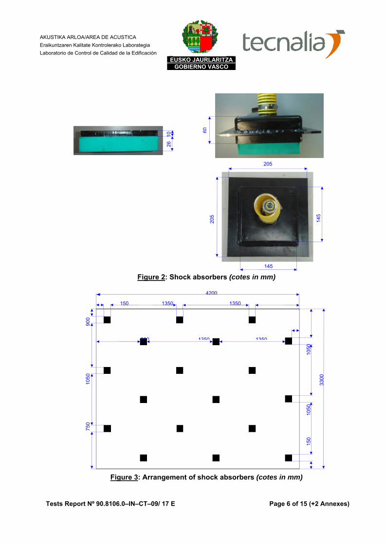
The tested sample consists on a reinforced concrete floating slab (100 mm thick) that was raised 25 mm with a shock absorber system (photos and figures 1-3).
Figure 1: Sketch of floating slab on normalized floor Floating slab: HM-20-B 20 concrete reinforced with double wire mesh (Ø 5 mm and 30x20 cm). The double wire mesh (one tied to the other) was posed over the shock absorbers (photo 4). These shock absorbers had the measured dimensions of 205 x 205 mm (figure 2) and were arranged as detailed in figure 3. Sylomer of 13 mm thick was placed around the whole perimeter between the wall of the heavyweight floor and the floating slab. Protective, double and transparent PVC film was placed to cover the Sylomer as well the surface of the heavyweight floor. Once the concrete set, the slab was raised. The dimensions of the sample were 4,2 m x 3,3 m (13,86 m2).
125 mm
Sylomer (13 mm)
Floating slab (100 mm) Shock absorber Air gap
(25 mm)
Normalized heavyweight floor: reinforced concrete 15 cm thick
PVC Double film
Double wire mesh (Ø 5 and
30x20 cm)
AKUSTIKA ARLOA/AREA DE ACUSTICA Eraikuntzaren Kalitate Kontrolerako Laborategia Laboratorio de Control de Calidad de la Edificación
Tests Report Nº 90.8106.0–IN–CT–09/ 17 E Page 6 of 15 (+2 Annexes)
EUSKO JAURLARITZAGOBIERNO VASCO
Figure 2: Shock absorbers (cotes in mm)
Figure 3: Arrangement of shock absorbers (cotes in mm)
4200
150
105
0
1050
150 1350 1350
75
0
1
050
900
3300
900 1350 1350
60
205
205
145
145
2
6 1
0
AKUSTIKA ARLOA/AREA DE ACUSTICA Eraikuntzaren Kalitate Kontrolerako Laborategia Laboratorio de Control de Calidad de la Edificación
Tests Report Nº 90.8106.0–IN–CT–09/ 17 E Page 7 of 15 (+2 Annexes)
EUSKO JAURLARITZAGOBIERNO VASCO
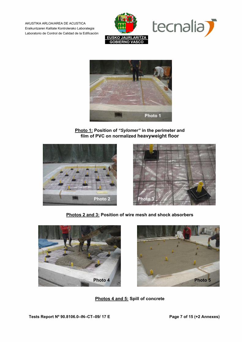
Photo 1: Position of “Sylomer” in the perimeter and film of PVC on normalized heavyweight floor
Photos 2 and 3: Position of wire mesh and shock absorbers
Photos 4 and 5: Spill of concrete
Photo 4 Photo 5
Photo 2 Photo 3
Photo 1

AKUSTIKA ARLOA/AREA DE ACUSTICA Eraikuntzaren Kalitate Kontrolerako Laborategia Laboratorio de Control de Calidad de la Edificación
Tests Report Nº 90.8106.0–IN–CT–09/ 17 E Page 8 of 15 (+2 Annexes)
EUSKO JAURLARITZAGOBIERNO VASCO
Photo 6: Raising of concrete slab
Photo 7: View of sample in the test rooms
Photo 6
Photo 7

AKUSTIKA ARLOA/AREA DE ACUSTICA Eraikuntzaren Kalitate Kontrolerako Laborategia Laboratorio de Control de Calidad de la Edificación
Tests Report Nº 90.8106.0–IN–CT–09/ 17 E Page 9 of 15 (+2 Annexes)
EUSKO JAURLARITZAGOBIERNO VASCO
5.3.- Laboratory test facilities
The tests were performed in the vertical transmission rooms, composed of a source and a receiving room. The reception room is composed of an external and an internal concrete box, of 20 and 10 cm thick each one, disconnected by an anti-vibratory system and an air chamber 10 cm thick with fibreglass within. The specimen was installed by moving away vertically the source room from the receiving one.
These rooms fulfill the standard EN ISO 140-1:1997.
A sketch of vertical transmission rooms is included in figure 4.
Figure 4: Sketch of the vertical transmission rooms
Source room
Receiving room
Test specimen

AKUSTIKA ARLOA/AREA DE ACUSTICA Eraikuntzaren Kalitate Kontrolerako Laborategia Laboratorio de Control de Calidad de la Edificación
Tests Report Nº 90.8106.0–IN–CT–09/ 17 E Page 10 of 15 (+2 Annexes)
EUSKO JAURLARITZAGOBIERNO VASCO
5.4.- Equipment
Vertical sound room Vertical reception room Microphones Brüel & Kjær 4943; Nº 2534064 Brüel & Kjær 4943; Nº 2534065 Preamplifiers Brüel & Kjær 2669; Nº 1948764 Brüel & Kjær 2669; Nº 2025844 Sound sources Brüel & Kjær 4296; Nº 2071427 BR 112 T/A Booms Brüel & Kjær 3923; Nº 2036584 Brüel & Kjær 3923; Nº 2036585 Tapping machine Brüel & Kjær 3204; Nº 1362917
Control room Analyser Brüel & Kjær 2144; Nº 1893979 Amplifier LAB 300; Nº 970-967 Equalizer Sony, SRP-E100; Nº 400238 Calibrator Brüel & Kjær 4231; Nº 2061476 Atmospheric conditions meter Testo 0560 4540 Nº 711.88490007GB
6.- TEST PROCEDURE AND EVALUATION
6.1.- Reduction of impact sound pressure level
The improvement of impact noise insulation of a sample is characterized by the reduction of impact sound pressure level (ΔL).
The reduction of impact sound pressure level (ΔL) of the sample under test for the one-third-octave band is calculated from the difference of normalized impact sound pressure level of the standardized heavyweight floor without and with the floating slab, according the following formula:
ΔL = Ln,0 – Ln
Ln,0: Standardized impact sound pressure level of the standardized heavyweight floor, between 100 and 500 Hz.
Ln: Standardized impact sound pressure level of the standardized heavyweight floor with the floating slab, between 100 and 500 Hz.
AKUSTIKA ARLOA/AREA DE ACUSTICA Eraikuntzaren Kalitate Kontrolerako Laborategia Laboratorio de Control de Calidad de la Edificación
Tests Report Nº 90.8106.0–IN–CT–09/ 17 E Page 11 of 15 (+2 Annexes)
EUSKO JAURLARITZAGOBIERNO VASCO
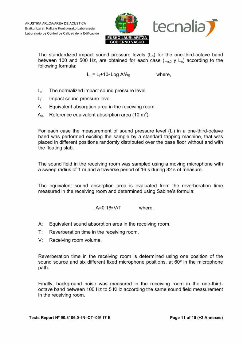
The standardized impact sound pressure levels (Ln) for the one-third-octave band between 100 and 500 Hz, are obtained for each case (Ln,0 y Ln) according to the following formula:
Ln = Li+10∗Log A/A0 where,
Ln: The normalized impact sound pressure level. Li: Impact sound pressure level. A: Equivalent absorption area in the receiving room. A0: Reference equivalent absorption area (10 m2). For each case the measurement of sound pressure level (Li) in a one-third-octave band was performed exciting the sample by a standard tapping machine, that was placed in different positions randomly distributed over the base floor without and with the floating slab. The sound field in the receiving room was sampled using a moving microphone with a sweep radius of 1 m and a traverse period of 16 s during 32 s of measure. The equivalent sound absorption area is evaluated from the reverberation time measured in the receiving room and determined using Sabine’s formula:
A=0.16∗V/T where,
A: Equivalent sound absorption area in the receiving room. T: Reverberation time in the receiving room. V: Receiving room volume.
Reverberation time in the receiving room is determined using one position of the sound source and six different fixed microphone positions, at 60º in the microphone path. Finally, background noise was measured in the receiving room in the one-third-octave band between 100 Hz to 5 KHz according the same sound field measurement in the receiving room.

AKUSTIKA ARLOA/AREA DE ACUSTICA Eraikuntzaren Kalitate Kontrolerako Laborategia Laboratorio de Control de Calidad de la Edificación
Tests Report Nº 90.8106.0–IN–CT–09/ 17 E Page 12 of 15 (+2 Annexes)
EUSKO JAURLARITZAGOBIERNO VASCO
All the testing equipment was calibrated just before and after every measurement.
6.2.- Sound reduction improvement index
The improvement of airborne sound insulation of a sample is characterized by the Sound reduction improvement index (ΔR).
The sound reduction improvement index (ΔR) of the sample under test for each one-third-octave band is calculated according to EN ISO 140-16, as the difference between the sound reduction index of the normalized heavyweight floor with and without the floating slab, according to the following formula:
ΔR = Rwith – Rwithout
Rwith: Sound reduction index of the heavyweight floor with floating slab, between 100 and 500 Hz.
Rwithout: Sound reduction index of the heavyweight floor without floating slab, between 100 and 500 Hz.
The sound reduction indexes (R) in one-third-octave band between 100 Hz and 500 Hz is calculated for each case (Rwith and Rwithout) according to EN ISO 140-3 standard using the following formula:
R=L1-L2+10∗Log S/A where,
L1: Average sound pressure level in the source room. L2: Average sound pressure level in the receiving room. S: Test specimen area.
A: Equivalent sound absorption area in the receiving room.
For each case, the measurement of the average sound pressure levels L1 and L2 were performed emitting an equalized white noise (between 100 and 500 Hz) with a moving sound source.
AKUSTIKA ARLOA/AREA DE ACUSTICA Eraikuntzaren Kalitate Kontrolerako Laborategia Laboratorio de Control de Calidad de la Edificación
Tests Report Nº 90.8106.0–IN–CT–09/ 17 E Page 13 of 15 (+2 Annexes)
EUSKO JAURLARITZAGOBIERNO VASCO
The sound field in the source and receiving room were sampled using different fixed positions of microphone in the case of floating slab on standardized heavyweight floor and using a moving microphone with a sweep radius of 1 m and a traverse period of 16 s during 32 s of measure in the case of the standardized heavyweight floor. The equivalent sound absorption area is evaluated from the reverberation time measured in the receiving room using Sabine’s formula:
A=0.16∗V/T where,
A: Equivalent sound absorption area in the receiving room. T: Reverberation time in the receiving room. V: Receiving room volume.
Reverberation time in the receiving room is determined using one position of the sound source and six different fixed microphone positions, at 60º in the microphone path. Finally, background noise was measured in the receiving room in the one-third-octave band between 100 Hz to 5 KHz using different fixed positions of microphone in the case of floating slab on standardized heavyweight floor, and using a moving microphone with a sweep radius of 1 m and a traverse period of 16 s during 32 s of measure in the case of the standardized heavyweight floor. All the testing equipment was calibrated just before and after every measurement
7.- RESULTS
7.1.- Reduction of impact sound pressure level
Annex I presents the following results of reduction of impact noise for the tested sample:
● The reduction of impact sound pressure level, ΔL, in the one-third-octave band between 100 Hz to 5 KHz, in table and graphic.
AKUSTIKA ARLOA/AREA DE ACUSTICA Eraikuntzaren Kalitate Kontrolerako Laborategia Laboratorio de Control de Calidad de la Edificación
Tests Report Nº 90.8106.0–IN–CT–09/ 17 E Page 14 of 15 (+2 Annexes)
EUSKO JAURLARITZAGOBIERNO VASCO
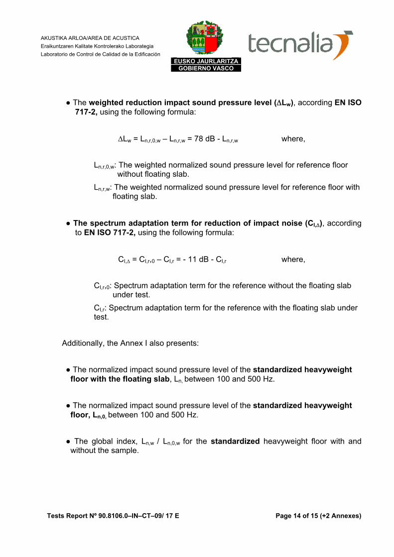
● The weighted reduction impact sound pressure level (ΔLw), according EN ISO 717-2, using the following formula:
ΔLw = Ln,r,0,w – Ln,r,w = 78 dB - Ln,r,w where,
Ln,r,0,w: The weighted normalized sound pressure level for reference floor without floating slab.
Ln,r,w: The weighted normalized sound pressure level for reference floor with floating slab.
● The spectrum adaptation term for reduction of impact noise (CI,Δ), according to EN ISO 717-2, using the following formula:
CI,Δ = CI,r,0 – CI,r = - 11 dB - CI,r where,
CI,r,0: Spectrum adaptation term for the reference without the floating slab under test.
CI,r: Spectrum adaptation term for the reference with the floating slab under test.
Additionally, the Annex I also presents:
● The normalized impact sound pressure level of the standardized heavyweight floor with the floating slab, Ln, between 100 and 500 Hz.
● The normalized impact sound pressure level of the standardized heavyweight floor, Ln,0, between 100 and 500 Hz.
● The global index, Ln,w / Ln,0,w for the standardized heavyweight floor with and without the sample.
AKUSTIKA ARLOA/AREA DE ACUSTICA Eraikuntzaren Kalitate Kontrolerako Laborategia Laboratorio de Control de Calidad de la Edificación
Tests Report Nº 90.8106.0–IN–CT–09/ 17 E Page 15 of 15 (+2 Annexes)
EUSKO JAURLARITZAGOBIERNO VASCO
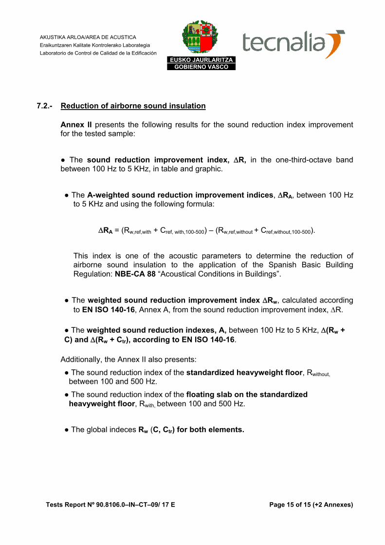
7.2.- Reduction of airborne sound insulation
Annex II presents the following results for the sound reduction index improvement for the tested sample:
● The sound reduction improvement index, ΔR, in the one-third-octave band between 100 Hz to 5 KHz, in table and graphic.
● The A-weighted sound reduction improvement indices, ΔRA, between 100 Hz to 5 KHz and using the following formula:
ΔRA = (Rw,ref,with + Cref, with,100-500) – (Rw,ref,without + Cref,without,100-500).
This index is one of the acoustic parameters to determine the reduction of airborne sound insulation to the application of the Spanish Basic Building Regulation: NBE-CA 88 “Acoustical Conditions in Buildings”.
● The weighted sound reduction improvement index ΔRw, calculated according to EN ISO 140-16, Annex A, from the sound reduction improvement index, ΔR.
● The weighted sound reduction indexes, A, between 100 Hz to 5 KHz, Δ(Rw + C) and Δ(Rw + Ctr), according to EN ISO 140-16.
Additionally, the Annex II also presents:
● The sound reduction index of the standardized heavyweight floor, Rwithout, between 100 and 500 Hz.
● The sound reduction index of the floating slab on the standardized heavyweight floor, Rwith, between 100 and 500 Hz.
● The global indeces Rw (C, Ctr) for both elements.

Annex I to Report N90.8106.0-IN-CT-09/ 17 E Page 1 of 1
EMPLEGU ETA GIZARTE POLITIKETAKO SAILA Etxebizitza Zuzendaritza Eraikuntzaren Kalitate Kontrolerako Laborategia
DEPARTAMENTO DE EMPLEO Y POLÍTICAS SOCIALES Dirección de Vivienda Laboratorio de Control de Calidad de la Edificación
This document is a copy in PDF of the original Report, for request of our client.
Reduction of Transmitted Impact Noise according to EN ISO 140-8:1998
Laboratory Measurements
Applicant: APLICACIONES MECÁNICAS DEL CAUCHO, S.A. Test date: June 24th, 2009. Test specimen: Reinforced concrete floating slab, 100 mm thick, rised 25 mm by a shock absorber system, as
detailed in the report.
Heavyweight floor: base floor of reinforced concrete, 15 cm thick, tested on June 26th, 2009 (Rwithout). Receiving room volume: 64,7m3 Test specimen area: 13,86 m2 (3,3x4,2 m)
Estimated superficial mass: 250 kg/m2 T rooms: 17,3 ºC HR rooms : 77 %
Weighted Reduction of impact noise according to EN ISO 717-2:1997 ∆Lw (CI,∆): 34 (-11) dB
Results based on measurements with artificial source and under conditions of laboratory (engineering method). * Ln ≤ showed value and ΔL ≥ showed value (measurement limits)
Nº of result: B0910–17–M25 MRI Signature: Acoustics Area Date of report: July 14th, de 2.009 Managed by Date of translation: January 10th, 2.014
f (Hz) Ln (dB) Ln,0 (dB) ΔL (dB) 100 47,2 65,1 17,9 125 46,9 60,5 13,6 160 53,2 67,5 14,3 200 49,5 65,3 15,8 250 41,8 65,4 23,6 315 37,3 64,7 27,4 400 34,5 65,9 31,4 500 34,3 67,5 33,2 630 31,9 68,0 36,1 800 32,9 70,1 37,2
1000 37,3 70,4 33,1 1250 38,9 70,7 31,8 1600 32,5 70,5 38,0 2000 27,8 70,3 42,5 2500 22,9 69,3 46,4 3150 15,3* 68,1 52,8* 4000 14,1* 66,2 52,1* 5000 11,6* 63,6 52,0*
Ln,w / Ln,0,w 41 76
ΔL
(dB
)
5
10
15
20
25
30
35
40
45
50
55
6010
012
516
020
025
031
540
050
063
080
010
0012
5016
0020
0025
0031
5040
0050
00
Frecuencies (Hz)
Red
uctio
n of
impa
ct s
ound
pre
sure
leve
l im
pact
os,
4 / L E 4 5 6
125 mm
Sylomer (13 mm)
Floating gap (100 mm)
Shock absorber Air chamber
(25 mm)
Normalized heavyweight floor: reinforced concrete 15 cm thick
PVC Double film
Double wire mesh
(Ø 5 and 30x20 cm)

Annex II to Report N90.8106.0-IN-CT-09/ 17 E Page 1 of 1
EMPLEGU ETA GIZARTE POLITIKETAKO SAILA Etxebizitza Zuzendaritza Eraikuntzaren Kalitate Kontrolerako Laborategia
DEPARTAMENTO DE EMPLEO Y POLÍTICAS SOCIALES Dirección de Vivienda Laboratorio de Control de Calidad de la Edificación
This document is a copy in PDF of the original Report, for request of our client.
Sound reduction improvement index according to EN ISO 140-16:2006
Laboratory Measurements according to EN ISO 140-3:1995
Applicant: APLICACIONES MECÁNICAS DEL CAUCHO, S.A. Test date: June 24th, 2009. Test specimen: Floating floor covering of reinforced concrete, 100 mm thick, rised 25 mm by a shock absorber
system, as detailed in the report.
Heavyweight floor: base floor of reinforced concrete, 15 cm thick, tested on June 26th, 2009 (Rwithout). Receiving room volume: 64,7m3 Source room volume: 53,6 m3 Test specimen area: 13,86 m2 (3,3x4,2 m)
Estimated superficial mass: 250 kg/m2 T rooms: 17,3 ºC HR rooms : 77 %
f (Hz) Rwith (dB) Rwithout (dB) ∆R (dB)100 48,4* 34,8 13,6* 125 53,7* 42,6 11,1* 160 54,6* 39,6 15,0* 200 58,1* 47,6 10,5* 250 63,0 47,7 15,3 315 67,6* 52,3 15,3* 400 70,4* 54,9 15,5* 500 71,0* 56,0 15,0* 630 72,3* 57,7 14,6* 800 72,8 59,8 13,0
1000 72,0 60,8 11,2 1250 71,9 62,2 9,7 1600 74,9 63,8 11,1 2000 80,8* 66,8 14,0* 2500 87,5* 70,3 17,2* 3150 91,2* 74,1 17,1* 4000 91,9* 76,1 15,8* 5000 92,3* 76,9 15,4*
Rw (C; Ctr) 72 (-2; -7) 58 (-2; -7) RA 70,9 57,5
Sound reduction improvement indices: ∆RA: 13 dBA ∆Rw : 13 dB ∆(Rw+C) : 13 dBA ∆(Rw+Ctr)
: 13 dBA
Evaluation based on laboratory measurement results obtained by an engineering method. * Rwith and ∆R ≥ showed value (measurement limit)
Nº of result: B0910–17–M25 MRA Signature: Acoustics Area Date of report: July 14th, de 2.009 Managed by Date of translation: January 10th, 2.014
4 / L E 4 5 6
0
10
20
30
100
125
160
200
250
315
400
500
630
800
1000
1250
1600
2000
2500
3150
4000
5000
Frecuencies (Hz)
Red
uctio
n of
airb
orne
sou
nd in
sula
tion
∆R (d
B)
125 mm
Sylomer (13 mm)
Floating slab(100 mm)
Shock absorber Air gap (25 mm)
Normalized heavyweight floor: reinforced concrete 15 cm thick
PVC Double film
Double wire
mesh (Ø 5 and
30x20 cm)