testing of statcom model in ieee power system network using pscad
TRANSCRIPT
TESTING OF STATCOM MODEL IN IEEE POWER SYSTEM
NETWORK USING PSCAD SOFTWARE
MOHD FIRDAUS BIN DAUD
UNIVERSITI MALAYSIA PAHANG

“I hereby acknowledge that the scope and quality of this thesis is qualified for the
award of the Bachelor of Electrical Engineering (Power System)”
Signature : ______________________________________________
Name : NORHAFIDZAH BTE. MOHD SAAD
Date : 10 NOVEMBER 2008
TESTING OF STATCOM MODEL IN IEEE POWER SYSTEM NETWORK USING
PSCAD SOFTWARE
MOHD FIRDAUS BIN DAUD
This thesis is submitted as partial fulfillment of the requirements for the award of the
Bachelor of Electrical Engineering (Power System)
Faculty of Electrical & Electronics Engineering
University Malaysia Pahang
NOVEMBER, 2008
ii
“All the trademark and copyrights use herein are property of their respective owner.
References of information from other sources are quoted accordingly; otherwise the
information presented in this report is solely work of the author.”
Signature : ____________________________
Author : MOHD FIRDAUS BIN DAUD
Date : 10 NOVEMBER 2008

iii
To my beloved family and friends.

iv
ACKNOWLEDGEMENTS
In the name of Allah s.w.t., most gracious, most merciful.
Firstly, I would like to thank my project supervisor, Pn. Norhafidzah Bte. Mohd
Saad for her never ending guidance and support that she given to me in completing this
project.
Secondly, I would like to thank to my beloved family members for their loves
and support throughout my studies in University Malaysia Pahang (UMP). For their
constant support and encouragement, helps me to keep going despite all the challenges I
face here.
Special thanks and gratitude to all the FKEE staff who have given me a great
help in completing this project.
Last but not least, I would like to say thanks to all of my friends and those who
help me in this project.
May God repay all of your kindness.
v
ABSTRACT
In any transmission system, the ultimate goals are to transmit power with high
quality, economical and low risk of system failure. The ever increasing of power
demands and loads especially non-linear loads making the power system network
become complex to operate and the system becomes insecure with large power flows
without adequate control. One way to introduce power system control is by applying
controller known as FACTS (Flexible AC Transmission System) controllers.
STATCOM (Static Synchronous Compensator) is one of the FACTS controllers and can
be introduced to the power system to regulate terminal voltage and to improve system’s
stability. By using IEEE 4 bus power system network, the effectiveness of STATCOM is
tested by applying the controller at the critical location of the power system. The critical
location of a power system is determined by the voltage drop that falls below 0.95 or
above 1.05. Using PSCAD/EMTDC simulation software, the simulations of STATCOM
in IEEE 4 bus power system networks can be realized. To verify the PSCAD/EMTDC
simulation results, load flow analysis are acquired using MATLAB software through
Hadi Saadat’s load flow analysis method. With these softwares, both systems’ power
flow can be compared to determine the effectiveness of STATCOM in the power
transmission system.
vi
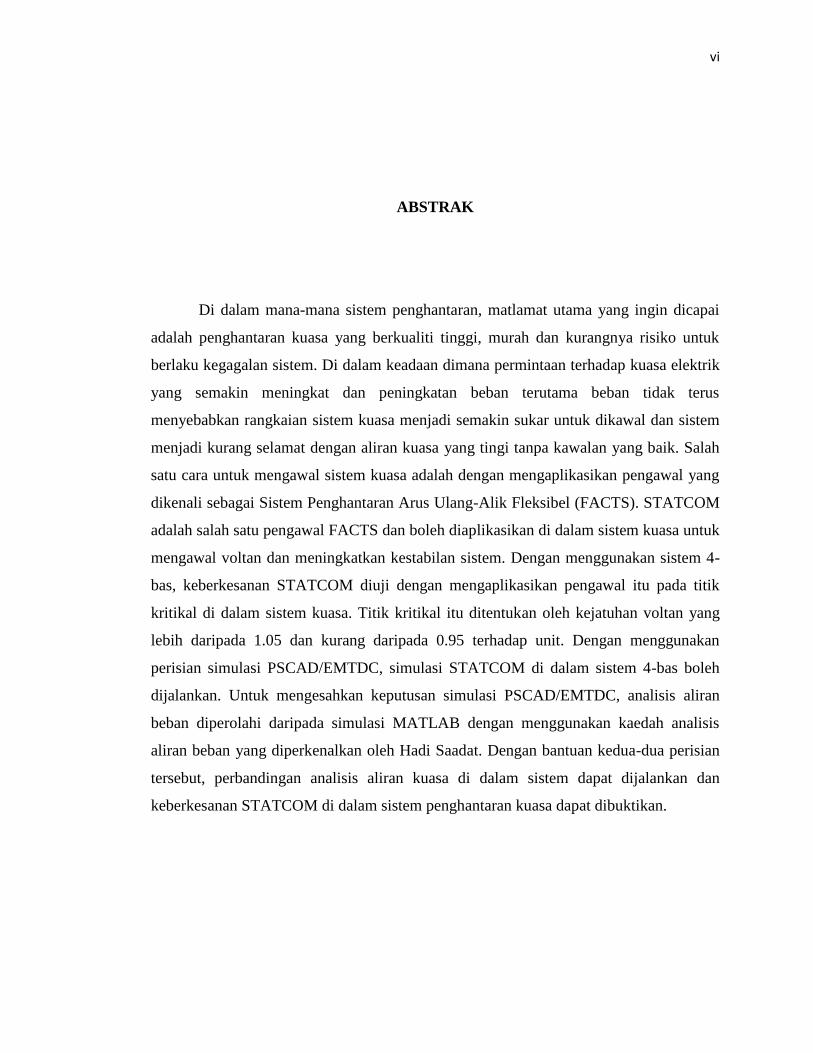
ABSTRAK
Di dalam mana-mana sistem penghantaran, matlamat utama yang ingin dicapai
adalah penghantaran kuasa yang berkualiti tinggi, murah dan kurangnya risiko untuk
berlaku kegagalan sistem. Di dalam keadaan dimana permintaan terhadap kuasa elektrik
yang semakin meningkat dan peningkatan beban terutama beban tidak terus
menyebabkan rangkaian sistem kuasa menjadi semakin sukar untuk dikawal dan sistem
menjadi kurang selamat dengan aliran kuasa yang tingi tanpa kawalan yang baik. Salah
satu cara untuk mengawal sistem kuasa adalah dengan mengaplikasikan pengawal yang
dikenali sebagai Sistem Penghantaran Arus Ulang-Alik Fleksibel (FACTS). STATCOM
adalah salah satu pengawal FACTS dan boleh diaplikasikan di dalam sistem kuasa untuk
mengawal voltan dan meningkatkan kestabilan sistem. Dengan menggunakan sistem 4-
bas, keberkesanan STATCOM diuji dengan mengaplikasikan pengawal itu pada titik
kritikal di dalam sistem kuasa. Titik kritikal itu ditentukan oleh kejatuhan voltan yang
lebih daripada 1.05 dan kurang daripada 0.95 terhadap unit. Dengan menggunakan
perisian simulasi PSCAD/EMTDC, simulasi STATCOM di dalam sistem 4-bas boleh
dijalankan. Untuk mengesahkan keputusan simulasi PSCAD/EMTDC, analisis aliran
beban diperolahi daripada simulasi MATLAB dengan menggunakan kaedah analisis
aliran beban yang diperkenalkan oleh Hadi Saadat. Dengan bantuan kedua-dua perisian
tersebut, perbandingan analisis aliran kuasa di dalam sistem dapat dijalankan dan
keberkesanan STATCOM di dalam sistem penghantaran kuasa dapat dibuktikan.
vii
TABLE OF CONTENTS
CHAPTER TITLE PAGE
DECLARATION ii
DEDICATION iii
ACKNOWLEGMENT iv
ABSTRACT v
ABSTRAK vi
TABLE OF CONTENTS vii
LIST OF TABLES x
LIST OF FIGURES xi
LIST OF ABBREVIATIONS xiii
LIST OF APPENDICES xiv
1.0 INTRODUCTION
1.1 General introduction 1
1.2 Objectives 2
1.3 Scope of Work 2
1.4 Thesis Outline 3
2.0 LITERATURE REVIEW
2.1 STATCOM 5
2.2 PSCAD/EMTDC 15
2.3 Summary 17
viii
CHAPTER TITLE PAGE
3.0 METHODOLOGY
3.1 Introduction 18
3.2 The IEEE 4 Bus System Simulation 18
3.3 Proposed Design of STATCOM 20
3.4 Control Strategies for STATCOM 22
3.4.1 Control of AC Voltage or Reactive Power 23
3.4.2 SPWM Switching Techniques 24
3.4.3 Generating Firing Pulses 25
3.5 Summary 26
4.0 RESULT AND DISCUSSION
4.1 Introduction 27
4.2 Simulation in PSCAD/EMTDC 27
4.3 STATCOM Location 34
4.4 Summary 43
5.0 CONCLUSION
5.1 Conclusion 44
5.2 Future recommendations 45

ix
CHAPTER TITLE PAGE
REFERENCES 46
Appendices A - D 48 - 55
x
LIST OF TABLES
TABLE NO. TITLE PAGE
4.1 Voltage level for 4 bus system without STATCOM. 29
4.2 Power flow for 4 bus system without STATCOM. 29
4.3 Voltage level for 4 bus system with STATCOM. 36
4.4 Power flow at each line with STATCOM. 36
xi
LIST OF FIGURES
FIGURE NO. TITLE PAGE
2.1 Schematic configuration of STATCOM diagram 5
2.2 Multi-pulse converter diagram 7
2.3 Cascade multilevel converter diagram. 8
2.4 ALSTOM’s Single phase three-link chain circuit 8
2.5 Diode-Clamped Multi Level Inverter (5 Levels) 9
2.6 Flying Capacitor Multi Level Inverter (5 levels) 10
2.7 Cascade Cell Multi Level Inverter of (9-levels Delta-connection) 11
2.8 The current flowing into the capacitor 13
2.9 Time intervals of a switching pattern 14
3.1 IEEE 4 bus system diagram. 19
3.2 The 4 bus system with STATCOM parallel at bus 3 21
3.3 Basic STATCOM control scheme. 22
3.4 AC Voltage or Reactive Power Control for STATCOM 23
3.5 Generation of triangular waveforms for STATCOM 24
3.6 Generation of sine waveforms for STATCOM 25
3.7 Interpolated Firing Pulses component for STATCOM 26
4.1 IEEE 4 bus system in PSCAD/EMTDC 28
4.2 Per-unit voltage for 4 bus system without STATCOM a) at
bus1, V1 b) at bus 2, V2 c) at bus 3, V3 d) at bus 4, V4.
31
4.3 Real power flow for 4 bus system without STATCOM a)
between bus 1 and bus 2, P1-2 b) between bus 1 and bus 3, P1-3
c) between bus 2 and bus 4, P2-4 d) between bus 3 and bus 4,
P3-4.
32
xii
FIGURE NO. TITLE PAGE
4.4 Reactive power flow for 4 bus system without STATCOM
a) between bus 1 and bus 2, Q1-2 b) between bus 1 and
bus 3, Q1-3 c) between bus 2 and bus 4, Q2-4 d) between
bus 3 and bus 4, Q3-4.
33
4.5 IEEE 4 bus system with STATCOM in PSCAD/EMTDC. 35
4.6 Per-unit voltages for 4 bus system with STATCOM a) at
bus 1, V1 b) at bus 2, V2 c) at bus 3, V3 d) at bus 4, V4.
38
4.7 Real power flow for 4 bus system with STATCOM a)
between bus 1 and bus 2, P1-2 b) between bus 1 and bus 3,
P1-3 c) between bus 2 and bus 4, P2-4 d) between bus 3 and
bus 4, P3-4.
39
4.8 Reactive power flow for 4 bus system with STATCOM a)
between bus 1 and bus 2, Q1-2 b) between bus 1 and bus
3, Q1-3 c) between bus 2 and bus 4, Q2-4 d) between bus
3 and bus 4, Q3-4.
40
4.9 STATCOM performances at bus 3 for a) Active power, P
b) Reactive power, Q c) RMS voltage.
42
xiii
LIST OF ABBREVIATIONS
AC Alternating Current
EMTDC Electromagnetic Transient Direct Current
GTO Gate Turn Off
IEEE The Institute of Electrical and Electronics Engineers
IGBT Insulated Gate Bipolar Transistor
MATLAB Matrix Laboratory
PLL Phase Locked Loop
PSCAD Power System Computer Aided Design
p.u. Per-unit
SPWM Sinusoidal Pulse Width Modulation
STATCOM Static Synchronous Compensator
VSC Voltage-sourced Converter
xiv
LIST OF APPENDICES
APPENDIX NO. TITLE PAGE
A IEEE 4 bus power system data. 48
B Power Flow Solution by Gauss-Seidel Method 50
C Per-unit to actual value conversion for IEEE 4 bus system. 53
D Biodata of the Author 55
CHAPTER 1
INTRODUCTION
1.1 General Introduction
Wherever power is to be transported, the basic requirements are; the power
transmission must be economical, the risk of power system failure must be low, and the
quality of the power supply must be high. Reactive power compensation is increasingly
becoming one of the most economic and effective solution to both traditional and new
problems in power transmission systems. As power transfers grow, with the ever-
increasing usage of non-linear loads, the power system network becomes increasingly
complex to operate and the system becomes insecure with large power flows without
adequate control [1].
To overcome these problems, STATCOM (Static Synchronous Compensator) is
introduced to the power system to regulate voltage and to improve dynamic stability.
Using IEEE 4 bus power system network along with STATCOM, this project’s goals is
to analyze the performance of the power system by introducing STATCOM into the
system. Both models will be simulated using PSCAD software and the result of the
performance will be analyzed and compared to determine the effectiveness of
STATCOM’s application in power system.
2
1.2 Objectives
The objective of this project is to;
i. To simulate STATCOM model in IEEE 4 bus power system network
using PSCAD software.
ii. To analyze the steady-state analysis of the 4 bus power system network
with and without STATCOM applied.
iii. To model STATCOM in IEEE 4 bus power system network sample.
1.3 Scope of Work
The scopes for this project are:
i. Modeling STATCOM in IEEE 4 bus power system network.
ii. Simulation on the model using PSCAD/EMTDC software.
iii. Analyze and compare the performance of 4 bus system with and without
STATCOM.
3
1.4 Thesis Outline
For the thesis outline, the progress elements are divided into chapters and the
details are as follows:
i. Chapter 1
This chapter consists of introduction, objectives, scope of work and
thesis outline. In introduction, the problem statement is stated here along with
the relevant solution. It’s to support the main objectives and the relevancy of
the proposed title. In the objectives, the goal of the project is stated in here.
It’s consists of the aim that must be achieved at the end of the project. In the
scope of work, the detailed work flow stated in here. This step by step flow
work is to keep the project’s progress on track and to meet the objective.
Lastly in thesis outline, the overall elements needed in the thesis are stated.
ii. Chapter 2
Chapter 2 is about literature review. It is the study on the others
papers, journal, website citation and other dependable sources that related to
the project. Literature review is crucial for every thesis not only to support
the proposed title but also for guidelines and references on the conducted
thesis.
4
iii. Chapter 3
Chapter 3 explains the methodology of the project. It is to describe in
details about the scope of project. In this part, every step on how to approach
the solutions to overcome the stated problems is described in details. It shows
how the work will be done. The details such as flow chart and schematic
diagram are shown in here.
iv. Chapter 4
Chapter 4 is about result and discussions. In this chapter, all the
finding related to the project is stated in here. Every output produce from the
project are stated, analyzed and explained briefly.
v. Chapter 5
This chapter consists of conclusion and future recommendations
section. In the conclusion, the project’s objectives and achieved result are
concluded. In future recommendations, the suggestions to improve the
existed project are stated.
vi. References
CHAPTER 2
LITERATURE REVIEW
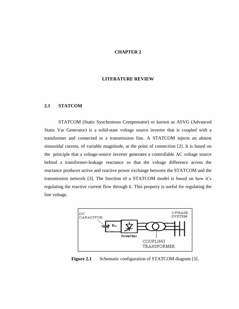
2.1 STATCOM
STATCOM (Static Synchronous Compensator) or known as ASVG (Advanced
Static Var Generator) is a solid-state voltage source inverter that is coupled with a
transformer and connected to a transmission line. A STATCOM injects an almost
sinusoidal current, of variable magnitude, at the point of connection [2]. It is based on
the principle that a voltage-source inverter generates a controllable AC voltage source
behind a transformer-leakage reactance so that the voltage difference across the
reactance produces active and reactive power exchange between the STATCOM and the
transmission network [3]. The function of a STATCOM model is based on how it’s
regulating the reactive current flow through it. This property is useful for regulating the
line voltage.
Figure 2.1 Schematic configuration of STATCOM diagram [3].
6
A STATCOM is basically a DC-AC voltage source inverter with an energy
storage unit, usually a DC capacitor and operates as a controlled Synchronous Voltage
Source (SVS) connected to the line through a coupling transformer as shown in Figure
2.1 [1]. The advantages of STATCOM are that its dynamic performance far exceeding
other compensator with the response time is less than 10ms [1]. It also can improve
transient stability by maintaining full capacitive output current at low voltage system.
The principle of control reactive power via STATCOM is well known that the
amount of type (capacitive or inductive) of reactive power exchange between the
STATCOM and the system can be adjusted by controlling the magnitude of STATCOM
output voltage with respect to that of system voltage [8]. When Q is positive, the
STATCOM supplies reactive power and when the Q is negative, the STATCOM absorbs
reactive power from the system [8]. Reactive power generation was achieved by
charging and discharging the energy storage capacitor [8]. The reactive power supplied
by the STATCOM is given by this equation.
(2.1)
Where;
Q = reactive power.
VSTATCOM = magnitude of STATCOM output voltage.
VS = magnitude of system voltage.
X = equivalent impedance between STATCOM and the system.
7
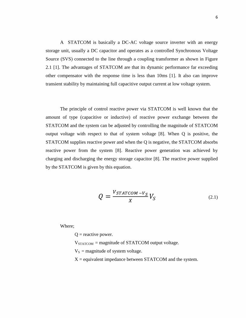
There are two types of STATCOM main circuit configurations, and that is multi-
pulse converter and multilevel converter. In the multi-pulse converter, the 3-phase
bridges are connected in parallel on the DC side where the bridges are magnetically
coupled through a zigzag transformer, and the transformer is usually arranged to make
the bridges appear in series viewed from the AC sides [1].
Figure 2.2 Multi-pulse converter diagram [1].
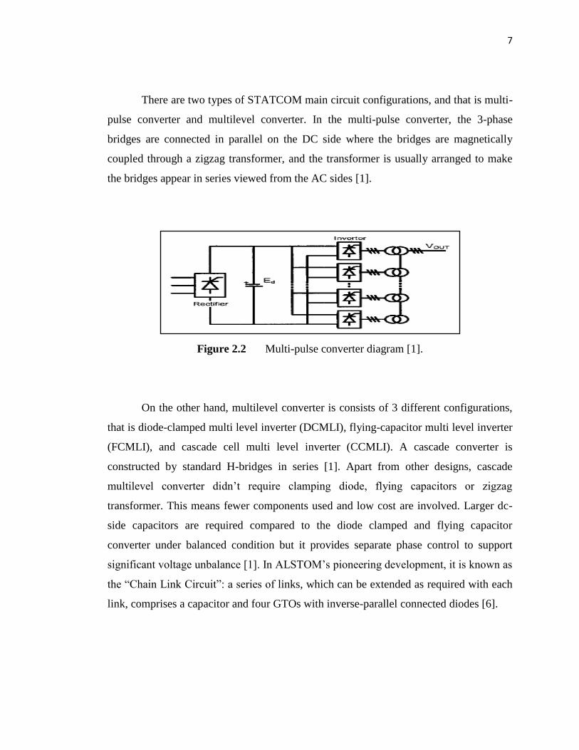
On the other hand, multilevel converter is consists of 3 different configurations,
that is diode-clamped multi level inverter (DCMLI), flying-capacitor multi level inverter
(FCMLI), and cascade cell multi level inverter (CCMLI). A cascade converter is
constructed by standard H-bridges in series [1]. Apart from other designs, cascade
multilevel converter didn’t require clamping diode, flying capacitors or zigzag
transformer. This means fewer components used and low cost are involved. Larger dc-
side capacitors are required compared to the diode clamped and flying capacitor
converter under balanced condition but it provides separate phase control to support
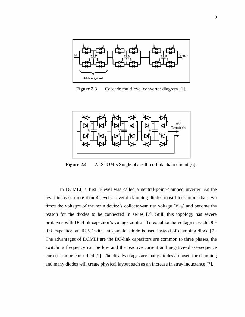
significant voltage unbalance [1]. In ALSTOM’s pioneering development, it is known as
the “Chain Link Circuit”: a series of links, which can be extended as required with each
link, comprises a capacitor and four GTOs with inverse-parallel connected diodes [6].
8
Figure 2.3 Cascade multilevel converter diagram [1].
Figure 2.4 ALSTOM’s Single phase three-link chain circuit [6].
In DCMLI, a first 3-level was called a neutral-point-clamped inverter. As the
level increase more than 4 levels, several clamping diodes must block more than two
times the voltages of the main device’s collector-emitter voltage (VCE) and become the
reason for the diodes to be connected in series [7]. Still, this topology has severe
problems with DC-link capacitor’s voltage control. To equalize the voltage in each DC-
link capacitor, an IGBT with anti-parallel diode is used instead of clamping diode [7].
The advantages of DCMLI are the DC-link capacitors are common to three phases, the
switching frequency can be low and the reactive current and negative-phase-sequence
current can be controlled [7]. The disadvantages are many diodes are used for clamping
and many diodes will create physical layout such as an increase in stray inductance [7].