testing of diesel fuel injection system - product...
TRANSCRIPT
1
كلية الهندسة
قسم الهندسة الميكانيكية
Testing of Diesel Fuel Injection System
حسين حامد عبد العاليالطالب:
امال حميد رحيم: ةالطالب
ة: صفا جابر ناصرالطالب
الطالبة: هبه منذر موسى
بأشراف
ثابت محمد فاضل .م.دا.
1028-1027السنة الدراسية

2

3
فخر...الى يا من اجمل اسمك بكل
الى من يرتعش قلبي لذكرك...
أبي الغالييا من اودعتني هلل اهديك هذا البحث
الى ادبي.....وحلمي
الى طريقي....المستقيم
الى طريق .... الهداية
الى ينبوع الصبر والتفاؤل واألمل
أمي الغاليةالى كل من في الوجود بعد اهلل ورسوله
الى سندي وقوتي ومالذي بعد اهلل
الى من اثروني على انفسهم
الى من علموني علم الحياة
أخوتيالى من اظهروا لي ماهو اجمل من الحياة
الى الذين حملوا اقدس رسالة في الحياة...
الى الذين مهدوا لنا طريق العلم والمعرفة...
الى من علمنا التفاؤل والمضي الى األمام...
الى من وقف الى جانبنا عندما ضللنا الطريق أ.م.د.محمد فاضل

4
Contain
List of figures…………………………………………………………..3
Abstract………………………………………………………………..4
Nomenclature………………………………………………………….5
Chapter One
1-1 Introduction ..……………………………..…………………6
1-2 Fuel injection system……………………………9
1-3 Nozzles……………………………...
1-4 The aim of the project work………………
1-5 Layout of the present work……………. Chapter Two
2-1 Introduction…………………………………….…………
2-2 Survey Of Literature……………………………………
2-3 Closing Remarks……………………………………..……
Chapter Three
3-1 Introduction……………………………………………….
3-2 Parts of the injection system……………………………….
Chapter Four
4-1 Introduction
4-2 Experimental Setup
4-3 Results and Discussion
4-4 Conclusions and Recommendations for future work
Chapter Five
1-5 Introduction……………………………………………….

5
List of Figures
Figure (1.1): Diesel engine.
Figure (1.2): Fuel pump.
Figure (3.1): Injection pump.
Figure (3.2): Motor device.
Figure (3.3): Gage pressure .
Figure (3.4): Fuel tank.
Figure (3.5): injectors.
Figure (3.6): tubes.
Figure (3.7): A tachometer.
Figure (3.8): motor.
List of Tables
Table (1):
Table (2):
6
NOMENCLATURE
A = area (m2)
𝐷 = diameter of nozzle(m)
𝑃 = Pressure(N
m2)
𝑄. = heat transferred(m3
s)
𝑉 = velocity(m
s)
𝑚. = 𝑚𝑎𝑠𝑠(𝑘𝑔
𝑠)
𝐶𝑑 = coefficient of discharge
𝑁 = 𝑠𝑝𝑒𝑒𝑑(𝑟𝑝𝑚)
ρ = density (kgm−3)
7
Abstract
The purpose from any successful diesel injection system is to inject fuel
accurately and the correct time to each cylinder.
This work investigates the performance of solid injection system experimentally
under different load and speed conditions. The experimental results reported
dramatic increase in the fuel volume flow rate of because of load increasing.
The measured results were collected at eight different speeds started from 293
rpm and ended with 1300 rpm. It is observed that each nozzle has its own history
in the sense of flow rate and velocity. Nozzle no. 4 was chosen as the best nozzle
depending on its higher flow rate and velocity as compared to other nozzles. The
experimental results are compared with the theoretical one and a reasonable
agreement was found.
8
Chapter One
Introduction
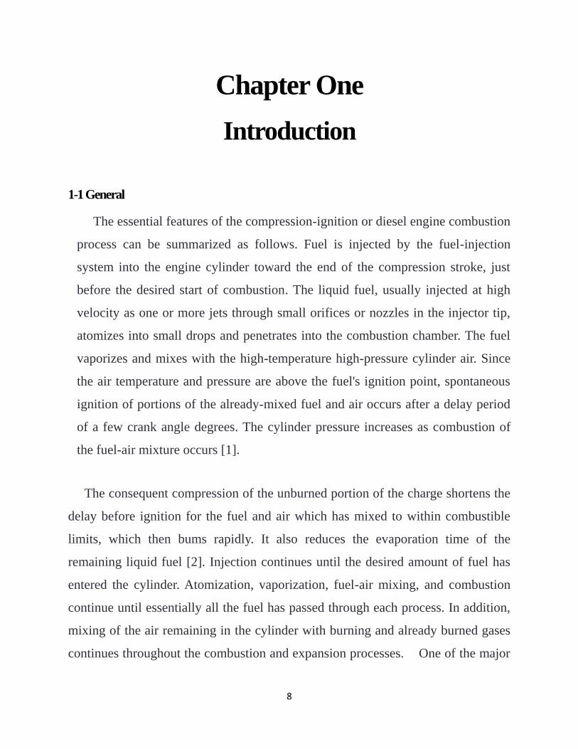
1-1 General The essential features of the compression-ignition or diesel engine combustion
process can be summarized as follows. Fuel is injected by the fuel-injection
system into the engine cylinder toward the end of the compression stroke, just
before the desired start of combustion. The liquid fuel, usually injected at high
velocity as one or more jets through small orifices or nozzles in the injector tip,
atomizes into small drops and penetrates into the combustion chamber. The fuel
vaporizes and mixes with the high-temperature high-pressure cylinder air. Since
the air temperature and pressure are above the fuel's ignition point, spontaneous
ignition of portions of the already-mixed fuel and air occurs after a delay period
of a few crank angle degrees. The cylinder pressure increases as combustion of
the fuel-air mixture occurs [1].
The consequent compression of the unburned portion of the charge shortens the
delay before ignition for the fuel and air which has mixed to within combustible
limits, which then bums rapidly. It also reduces the evaporation time of the
remaining liquid fuel [2]. Injection continues until the desired amount of fuel has
entered the cylinder. Atomization, vaporization, fuel-air mixing, and combustion
continue until essentially all the fuel has passed through each process. In addition,
mixing of the air remaining in the cylinder with burning and already burned gases
continues throughout the combustion and expansion processes. One of the major
9
problems for fuel injection systems is not getting a dribbles at the end of the
injection, even a small extra drip would throw off the combustion cycle. Another
problem is the cavitation it is produced due to pressure waves initiated by the
sudden closure of the needle valve in the injector at the end of effective stroke of
the pump plunger, and prevent it return.
In this project an effort has been made to investigate the performance of solid
fuel injection system under variable speed and load.
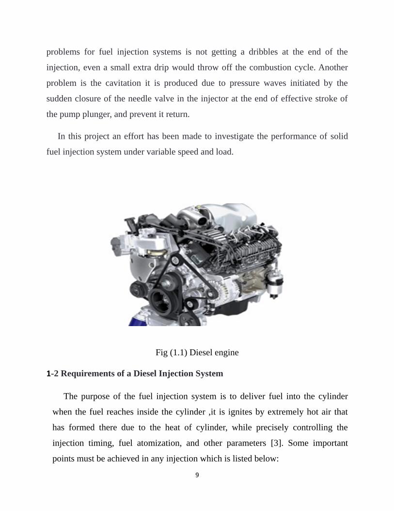
Fig (1.1) Diesel engine
1-2 Requirements of a Diesel Injection System
The purpose of the fuel injection system is to deliver fuel into the cylinder
when the fuel reaches inside the cylinder ,it is ignites by extremely hot air that
has formed there due to the heat of cylinder, while precisely controlling the
injection timing, fuel atomization, and other parameters [3]. Some important
points must be achieved in any injection which is listed below:

10
1. The fuel should be introduced into the combustion chamber within a precisely
defined period of the cycle.
2. The amount of the fuel injected per cycle should be metered very accurately.
3. The quantities of the fuel metered should vary to meet changing speed and load
requirements.
4. The injected fuel must be broken into very fine droplets i.e. good atomization
should be obtained.
5. The beginning and the end of injection should be sharp i.e. there should not be
any dribbling or after-injection.
6. The weight and size of fuel injection system must be minimum.
1.3 The Aim of the Project Work
The purpose of the present work is to investigate the performance of solid
injection system by measuring the quantity of fuel that injected from each nozzle
under different speed and injection pressure conditions.
1.4 Layout of the present work
This introduction makes up the first chapter, and is immediately followed by the
next chapter which reviews the past results published in the open literature on
injection system. Chapter three describes the experimental setup and procedure.
Chapter four is devoted to the presentation of results and the discussion of these
results. Chapter five presents the conclusions drawn from this work in addition to
some future suggestions to develop this work further.
11
Chapter Two
Types of Fuel Injection in Diesel Engine
2.1 Introduction
In diesel engine air is drawn into the cylinder during suction stroke and
compressed to a very high pressure, thus raising air temperature to a value required
to ignite the injected fuel into the cylinder [1]. Fuel is injected into the cylinder at
the end of the compression stroke, thus requiring a high injection pressure. During
the process of injection the fuel is broken into a fine spray of very small droplets.
These droplets take heat from the hot compressed air. The surfaces of these
droplets form vapor, which in turn mixes with air to form a fuel-air mixture.
2-2 Types of Injection systems
Diesel injection systems can be divided into two basic types. They are:
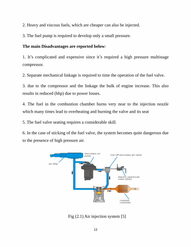
2.2.1 Air Injection: the fuel is metered and pumped to the fuel valve by a camshaft
driven the fuel pump. The fuel valve is opened by means of mechanical linkage
operated by the camshaft which controls the timing of injection [4]. The fuel valve
is also connected to a high pressure line fed by a multistage compressor which
supplies air at a pressure about 60 to 70 kgf/cm2. When the fuel valve is opened,
the blast sweeps along with it the fuel and a well-atomized fuel spray is sent to the
combustion chamber. This method is generally use in the large stationary and
marine engines. The advantages of air injection system are discussed below:
1. Good atomization obtained. A high indicated mean effective pressure can be
attained as rapid combustion results due to good mixing of fuel and air.
12
2. Heavy and viscous fuels, which are cheaper can also be injected.
3. The fuel pump is required to develop only a small pressure.
The main Disadvantages are reported below:
1. It’s complicated and expensive since it’s required a high pressure multistage
compressor.
2. Separate mechanical linkage is required to time the operation of the fuel valve.
3. due to the compressor and the linkage the bulk of engine increase. This also
results in reduced (bhp) due to power losses.
4. The fuel in the combustion chamber burns very near to the injection nozzle
which many times lead to overheating and burning the valve and its seat
5. The fuel valve seating requires a considerable skill.
6. In the case of sticking of the fuel valve, the system becomes quite dangerous due
to the presence of high pressure air.
Fig (2.1) Air injection system [5]
13
2.2.2 Solid injection: injection of fuel directly into the combustion chamber
without primary atomization is termed as solid injection. This is also called airless
mechanical injection [4]. Every solid injection must have:
(1) A pressurizing unit (the pump) and
(2) An atomizing unit (injector).
The different types of solid injection systems vary in the manner of operation and
control of these two basic elements. The main types of modern fuel injection
systems are:
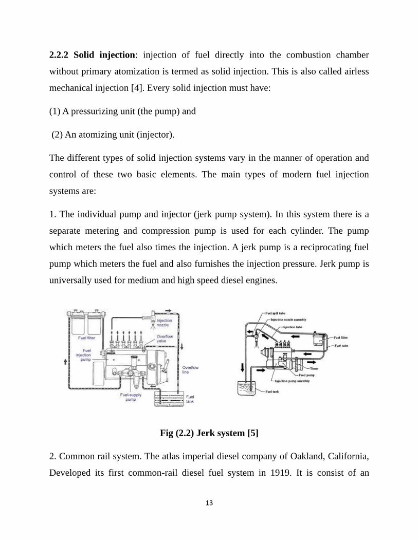
1. The individual pump and injector (jerk pump system). In this system there is a
separate metering and compression pump is used for each cylinder. The pump
which meters the fuel also times the injection. A jerk pump is a reciprocating fuel
pump which meters the fuel and also furnishes the injection pressure. Jerk pump is
universally used for medium and high speed diesel engines.
Fig (2.2) Jerk system [5]
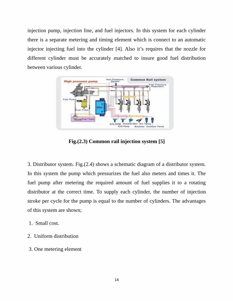
2. Common rail system. The atlas imperial diesel company of Oakland, California,
Developed its first common-rail diesel fuel system in 1919. It is consist of an
14
injection pump, injection line, and fuel injectors. In this system for each cylinder
there is a separate metering and timing element which is connect to an automatic
injector injecting fuel into the cylinder [4]. Also it’s requires that the nozzle for
different cylinder must be accurately matched to insure good fuel distribution
between various cylinder.
Fig.(2.3) Common rail injection system [5]
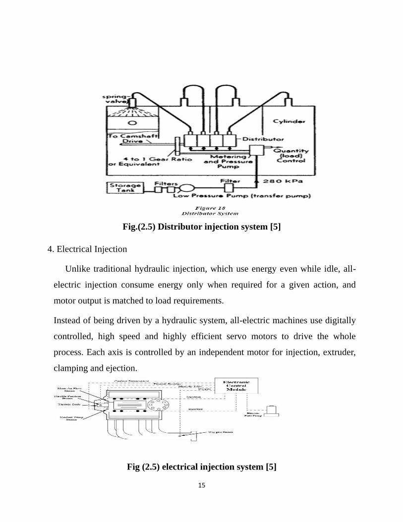
3. Distributor system. Fig.(2.4) shows a schematic diagram of a distributor system.
In this system the pump which pressurizes the fuel also meters and times it. The
fuel pump after metering the required amount of fuel supplies it to a rotating
distributor at the correct time. To supply each cylinder, the number of injection
stroke per cycle for the pump is equal to the number of cylinders. The advantages
of this system are shown;
1. Small cost.
2. Uniform distribution
3. One metering element
15
Fig.(2.5) Distributor injection system [5]
4. Electrical Injection
Unlike traditional hydraulic injection, which use energy even while idle, all-
electric injection consume energy only when required for a given action, and
motor output is matched to load requirements.
Instead of being driven by a hydraulic system, all-electric machines use digitally
controlled, high speed and highly efficient servo motors to drive the whole
process. Each axis is controlled by an independent motor for injection, extruder,
clamping and ejection.
Fig (2.5) electrical injection system [5]
16
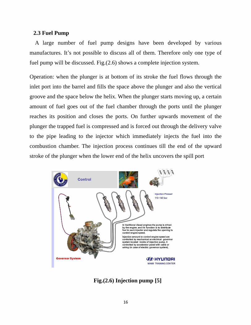
2.3 Fuel Pump
A large number of fuel pump designs have been developed by various
manufactures. It’s not possible to discuss all of them. Therefore only one type of
fuel pump will be discussed. Fig.(2.6) shows a complete injection system.
Operation: when the plunger is at bottom of its stroke the fuel flows through the
inlet port into the barrel and fills the space above the plunger and also the vertical
groove and the space below the helix. When the plunger starts moving up, a certain
amount of fuel goes out of the fuel chamber through the ports until the plunger
reaches its position and closes the ports. On further upwards movement of the
plunger the trapped fuel is compressed and is forced out through the delivery valve
to the pipe leading to the injector which immediately injects the fuel into the
combustion chamber. The injection process continues till the end of the upward
stroke of the plunger when the lower end of the helix uncovers the spill port
Fig.(2.6) Injection pump [5]
17
2.4 Injection Nozzles
The main requirements of an injector nozzle are as follows [4]:
(1) To inject fuel at sufficiently high pressure so that the fuel enters the cylinder
with a high velocity (less penetration).
(2) The penetration should not be high so as to impinge on cylinder walls. This
may result in poor staring.
(3) The fuel supply and cut off should be rapid. There should not be any dribbling.
The type of nozzle used is greatly dependent on the type of combustion chamber in
use. The mixing of fuel and air depends on the relative velocity between them,
which in turn is greatly affected by the nature of the air movement in the
combustion chamber. The injection nozzles may be classified as open or close type
Open type: has the fuel orifice, or orifices and the part of the fuel passageway
open to the burner or cylinder pressure at all types. Open burner are cheap but less
efficient and are rarely used, one example being opposite piston two stroke Junkers
diesel engines.
Closed type: the advantages of a closed nozzle as compared to those of an open
nozzle lie in its avoidance of pressure drop and in its control of injection pressure
also the needle cannot be blocked by deposits this nozzle is proffered in practice.
2.4.1 Component of Fuel Injector Nozzle
Fuel injector nozzle is composed of the following components. They are,
1. Nozzle holder
2. Pressure spring
3. Cap nut
4. Retaining nut

18
5. Pressure spindle and
6. Needle valve assemblies
Fig.(2.7) Nozzle assembly [5]
2.5 Closing Remarks
The previous sections deal with the analysis of different types of injection
systems. An attempt has been done to study the performance of solid injection
system experimentally. The pump supplies diesel to four injectors which inject fuel
through four scaled tubes instead of engine cylinders. The pump is rotating with
the aid of an electric motor instead of crankshaft in real engine.
19
Chapter Three
Experimental Work
3-1 Introduction
In general, the main function of the diesel fuel system is to inject the amount
of fuel into the engine cylinder and at the same time to all cylinders in which the
combustion stage will occur in a timely manner, The combustion occurs in the
diesel engine when the fuel mixture mixes with the compressed hot air and does
not use an electric spark as in the gasoline engine.
3-2 Parts of the injection system
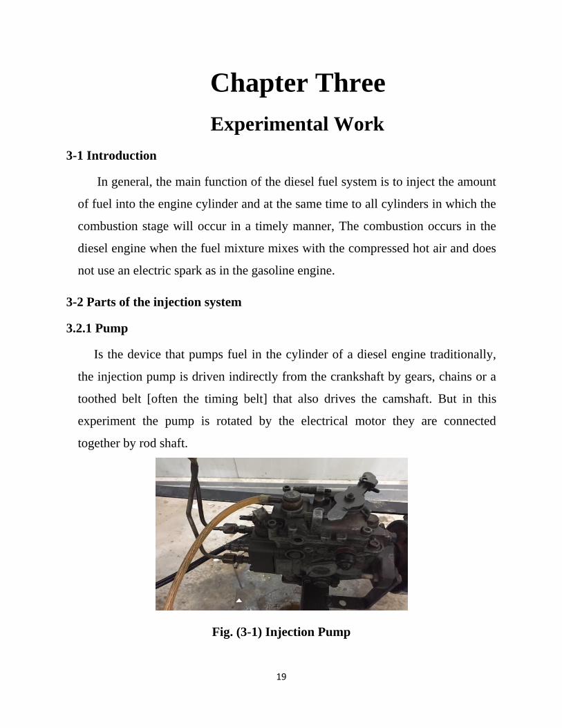
3.2.1 Pump
Is the device that pumps fuel in the cylinder of a diesel engine traditionally,
the injection pump is driven indirectly from the crankshaft by gears, chains or a
toothed belt [often the timing belt] that also drives the camshaft. But in this
experiment the pump is rotated by the electrical motor they are connected
together by rod shaft.
Fig. (3-1) Injection Pump
20
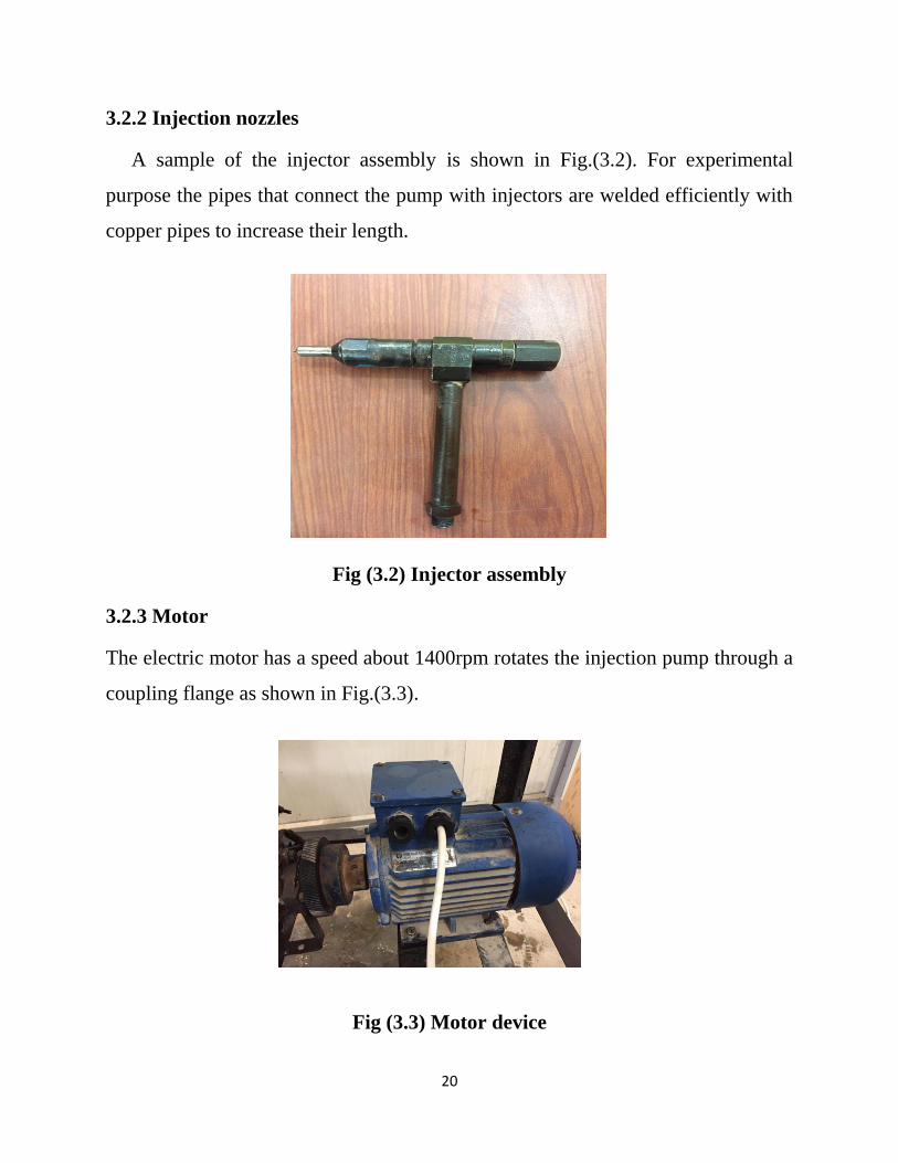
3.2.2 Injection nozzles
A sample of the injector assembly is shown in Fig.(3.2). For experimental
purpose the pipes that connect the pump with injectors are welded efficiently with
copper pipes to increase their length.
Fig (3.2) Injector assembly
3.2.3 Motor
The electric motor has a speed about 1400rpm rotates the injection pump through a
coupling flange as shown in Fig.(3.3).
Fig (3.3) Motor device
21
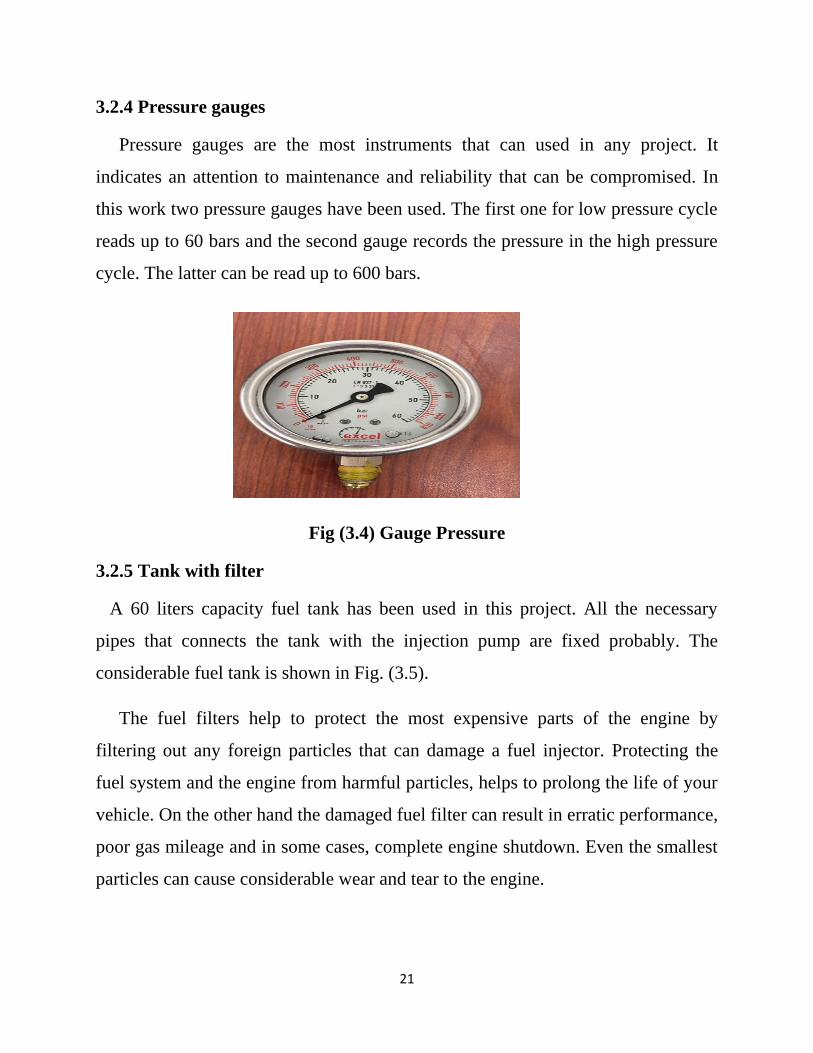
3.2.4 Pressure gauges
Pressure gauges are the most instruments that can used in any project. It
indicates an attention to maintenance and reliability that can be compromised. In
this work two pressure gauges have been used. The first one for low pressure cycle
reads up to 60 bars and the second gauge records the pressure in the high pressure
cycle. The latter can be read up to 600 bars.
Fig (3.4) Gauge Pressure
3.2.5 Tank with filter
A 60 liters capacity fuel tank has been used in this project. All the necessary
pipes that connects the tank with the injection pump are fixed probably. The
considerable fuel tank is shown in Fig. (3.5).
The fuel filters help to protect the most expensive parts of the engine by
filtering out any foreign particles that can damage a fuel injector. Protecting the
fuel system and the engine from harmful particles, helps to prolong the life of your
vehicle. On the other hand the damaged fuel filter can result in erratic performance,
poor gas mileage and in some cases, complete engine shutdown. Even the smallest
particles can cause considerable wear and tear to the engine.
22
Fig. (3.5) Fuel tank
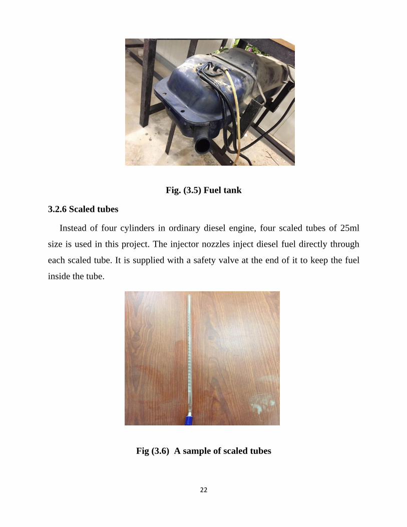
3.2.6 Scaled tubes
Instead of four cylinders in ordinary diesel engine, four scaled tubes of 25ml
size is used in this project. The injector nozzles inject diesel fuel directly through
each scaled tube. It is supplied with a safety valve at the end of it to keep the fuel
inside the tube.
Fig (3.6) A sample of scaled tubes
23
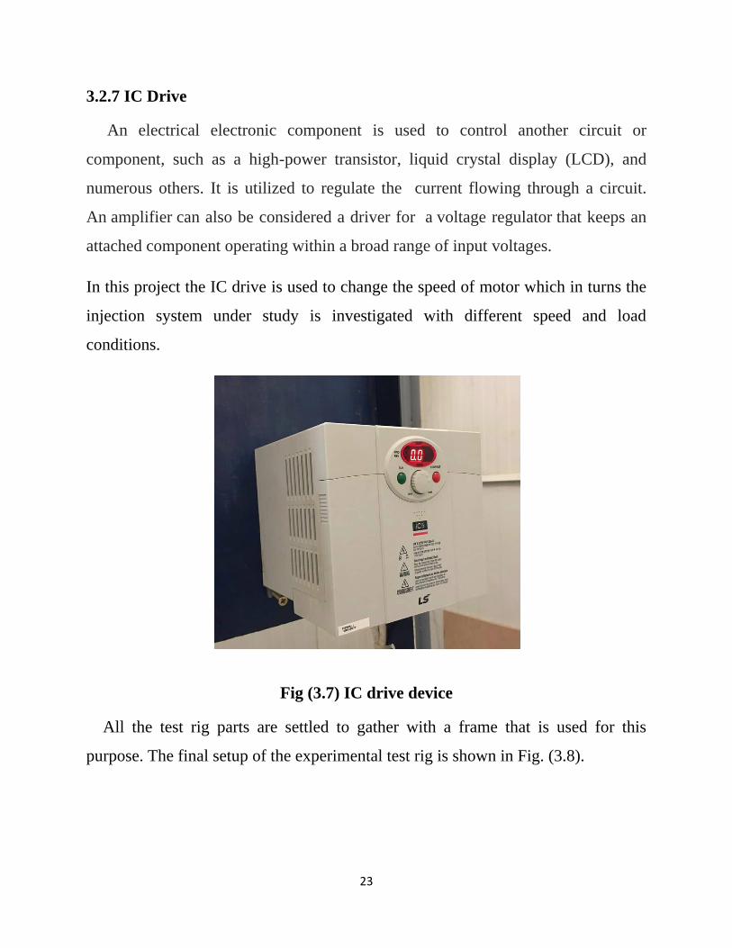
3.2.7 IC Drive
An electrical electronic component is used to control another circuit or
component, such as a high-power transistor, liquid crystal display (LCD), and
numerous others. It is utilized to regulate the current flowing through a circuit.
An amplifier can also be considered a driver for a voltage regulator that keeps an
attached component operating within a broad range of input voltages.
In this project the IC drive is used to change the speed of motor which in turns the
injection system under study is investigated with different speed and load
conditions.
Fig (3.7) IC drive device
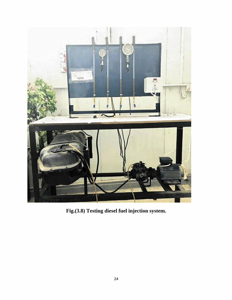
All the test rig parts are settled to gather with a frame that is used for this
purpose. The final setup of the experimental test rig is shown in Fig. (3.8).
24
Fig.(3.8) Testing diesel fuel injection system.
25
3.3 Experimental Procedures
The experimental steps start with pumping the diesel fuel to the injectors at high
pressure. The fuel is passing through filter which is used to protect the fuel pump.
Each injectors sprays the fuel though nozzle to the scaled tube. Then we set the
time to 20 sec using stop watch and measure the volume flow rate for each nozzle
at different speed. The motor speed is controlled by IC drive. The fuel is collected
inside the tubes and accumulates in it. The discharge valve in each tube is then
opened and repeat the same process at different speeds. The operating range of
motor speed is taken as (293,350, 445, 510, 700, 900, 1100, 1300) rpm
The flow velocity in each nozzle is calculated from equation below:
24// ndQV (3.1)
The diameter of nozzle is measure and found to be 0.6 mm
The mass flow rate is given by:
VAm f (3.2)
The density of fuel f is taken to be 830 kg/m3
The pressure of injection is measured with the aid of pressure gauge at each speed.
3.4 Theoretical Background
Theoretically the quantity of fuel injected per cycle depends upon the amount of
air available (displacement volume) and the load of the engine. The fuel is supplied
into the combustion chamber through the nozzle holes. Roughly the velocity of the
fuel through nozzle orifice can be given by:
26
(3.3)
tV : theoretical velocity of fuel.
C : orifice flow coefficient (0.66)
NP : pressure difference between injection and cylinder pressure
The total volume of the fuel injected per second Q is given by:
60
1
3604
2 N
NVndQ nt
(3.4)
nd : diameter of orifice, n : number of hole (=1), : injection duration
N : Engine revolution per minute.
Nffdf PACm
2 (3.5)
f
Ndt
PCV
2

27
Chapter Four
Results and Discussions
4.1 Introduction
In this chapter the experimental results are presented. The experimental findings
are measured at each motor speed. As mentioned before 8 speeds are chosen with
the help of tachometer.
Fig.(4.1) Volume flow rate with speed
Fig.(4.1) shows the effect of variable load condition in terms of motor speed on the
volume flow rate in each nozzle. An increasing the flow rate is observed as a result
of increasing speed due to increase in the pressure of injection which in turns
200 300 400 500 600 700 800 900 1000 1100 1200 1300
Speed (rpm)
0.20
0.40
0.60
0.80
1.00
1.20
vo
lum
e f
low
ra
te (
ml/s)
flow rate Vs Speed
Nozzel 1
Nozzel 2
Nozzel 3
Nozzel 4
28
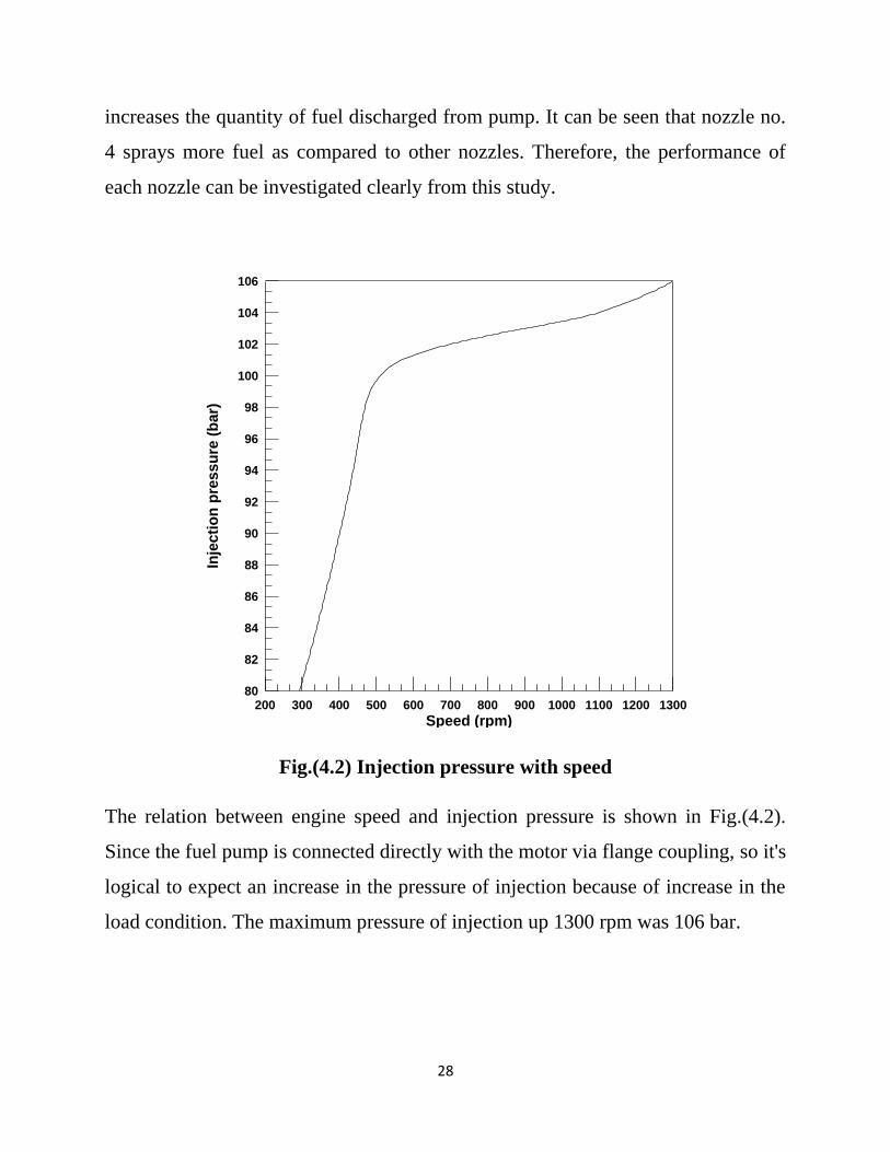
increases the quantity of fuel discharged from pump. It can be seen that nozzle no.
4 sprays more fuel as compared to other nozzles. Therefore, the performance of
each nozzle can be investigated clearly from this study.
Fig.(4.2) Injection pressure with speed
The relation between engine speed and injection pressure is shown in Fig.(4.2).
Since the fuel pump is connected directly with the motor via flange coupling, so it's
logical to expect an increase in the pressure of injection because of increase in the
load condition. The maximum pressure of injection up 1300 rpm was 106 bar.
200 300 400 500 600 700 800 900 1000 1100 1200 1300
Speed (rpm)
80
82
84
86
88
90
92
94
96
98
100
102
104
106
Inje
cti
on
pre
ssu
re (
ba
r)

29
Fig.(4.3) Injection pressure with speed
Fig.(4.3) displays the effect of variable speed on the flow velocity. The fuel
velocity is determined from equation (3.2). The velocity of fuel increases with
increasing the motor speed. While the velocity of nozzle 1 is 1.131 m/s at 293 rpm,
it was 3.399 m/s at 1300 rpm. At 1300 rpm the flow velocity of nozzle 4 is 7 %
higher flow velocity of nozzle one
The massage from this figure says: since the flow velocity of each nozzle is
differing from other nozzles, hence the performance of each nozzle is different.
200 300 400 500 600 700 800 900 1000 1100 1200 1300
Speed (rpm)
1.00
1.50
2.00
2.50
3.00
3.50
4.00
Ve
locit
y (
m/s
)
velocity vs. speed
Nozzel 1
Nozzel 2
Nozzel 3
Nozzel 4
30
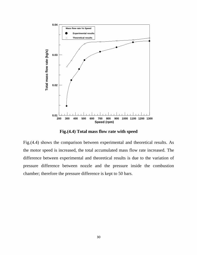
Fig.(4.4) Total mass flow rate with speed
Fig.(4.4) shows the comparison between experimental and theoretical results. As
the motor speed is increased, the total accumulated mass flow rate increased. The
difference between experimental and theoretical results is due to the variation of
pressure difference between nozzle and the pressure inside the combustion
chamber; therefore the pressure difference is kept to 50 bars.
200 300 400 500 600 700 800 900 1000 1100 1200 1300
Speed (rpm)
0.01
0.02
0.03
0.04
To
tal m
ass
flo
w r
ate
(kg
/s)
Mass flow rate Vs Speed
Experimental results
Theoretical results

31
Chapter Five
Conclusions and Future Work
5.1 Conclusions
The main conclusions are drawn from the present study:
1. Noticeable increase in the flow rate of injection as a result of increasing speed.
2. As the load increases, the pressure of injection increases.
3. Each nozzle has its own flow rate and velocity.
4. The experimental results confirmed that the best nozzle was nozzle no.4 followed by nozzle
no.3 then nozzle no.2 and finally nozzle no.1 comes.
5. The experimental device can be considered as a promising tool to investigate and calibrate
the performance of solid injection system.
5.2 Future Work
The main recommendations to develop this work in the future can be summarized below:
1. Study the performance of air injection system by inserting an air compressor to the test rig.
2. An accurate flow meter has to added after the pump and before the injectors
3. Simulation study using Solid works should be studied to compare the simulated results with
the experimental findings.

32
List of References
1) Introduction to internal combustion engine by J.B Heywood 1988.
2) Mohamed F. Al-Dowdy "Theoretical Study for The Influence of Biodiesel Addition on
The Combustion, Performance and Emissions Parameters of Single Cylinder Diesel
Engine", Journal of Babylon University/Engineering Sciences/ No.(5)/
Vol.(25): 2017.
3) A text book of internal combustion engines, by R.K Rajput, 2010.
4) Fundamentals of Internal combustion engine, by Gupta, 2008.
5) Hand book of diesel engines, by Klaus M. and Helmut T., Springer, 2010.
33
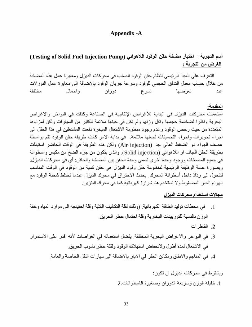
Appendix -A
(Testing of Solid Fuel Injection Pump) د الالهوائيمضخة حقن الوقواختبار : اسم التجربة
:غرض من التجربة ال
الديزل ومعايرة عمل هذه المضخة اتفي محرك الصلب حقن الوقودنظام لالتعرف على المبدأ الرئيسي
معدل التدفق الحجمي للوقود وسرعة جريان الوقود باإلضافة الى معايرة عمل النوزالتحساب من خالل
واحمال مختلفة دوران سرعلتعرضها عند
المقدمة:
كذلك في البواخر واالغراض و ية لألغراض اإلنتاجية في الصناعةاستعملت محركات الديزل في البدا
البحرية ونظرا لضخامة حجمها وثقل وزنها ولم تكن في حينها مالئمة للكثير من السيارات ولكن لمزاياها
المتعددة من حيث رخص الوقود وعدم وجود منظومة االشتغال المبخرة دفعت المشتغلين في هذا الحقل الى
في بداية االمر كانت طريقة حقن الوقود تتم بواسطة . رات واجراء التحسينات لجعلها مالئمةاجراء تحوي
ولكن هذه الطريقة في الوقت الحاضر استبدلت (Air injection) الضغط العالي جدا ذوعصف الهواء
والذي يتكون من جزء الضخ من مكبس واسطوانة .(Solid injectionبطريقة الحقن الجاف او الالهوائي )
في جميع المضخات ووجود وحدة أخرى تسمى وحدة الحقن بين المضخة والحاقن: أي في محركات الديزل.
من الوقود في الوقت المناسب وقود الديزل هي حقن كمية حقن وبصورة عامة الوظيفة الرئيسية لمنظومة
يحدث االحتراق في محرك الديزل عندما تختلط شحنة الوقود مع رك.أسطوانة المح داخللتتحول الى رذاذ
.الهواء الحار المضغوط وال تستخدم هنا شرارة كهربائية كما في محرك البنزين
مجاالت استخدام محركات الديزل
وخفة في محطات توليد الطاقة الكهربائية. )وذلك لقلة التكاليف الكلية وقلة احتياجه الى موارد المياه .1
الوزن بالنسبة للتوربينات البخارية وقلة احتمال حطر الحريق.
القاطرات .1
في البواخر واالغراض البحرية المختلفة. يفضل استعماله في الغواصات ألنه اقدر على االستمرار .3
في االشتغال لمدة أطول والنخفاض استهالك الوقود ولقلة خطر نشوب الحريق.
باإلضافة الى سيارات النقل الخاصة والعامة. الحفر في اآلبار واالنفاق ومكائنفي المناجم .4
ويشترط في محركات الديزل ان تكون:
2.ن وسريعة الدوران وصغيرة الاسطواناتخفيفة الوز. 1

34
.سهلة الإدارة في السرع المختلفة وبدء ادارتها في الأجواء الباردة. 2
.ذات الرائحة غازات العادم تحدث الكثير من الدخان او .ان لا3
(( DAdvantage of(iesel Engine) الديزل محركات مزايا
الوقود استهالك قلة .1
الوقود كلفة رخص .2
االستعمال في االمان توفير .3
العالية النهائية السرع في وخاصة متجانس يكون العزم الن( Torque)العزم .4
الشائعة وملحقاتها والمبخرة االشتعال منظومة وجود لعدم بالنظر( Performance) المحرك اداء .5
اكثر الديزل محرك فان لذلك المحرك عطالت من تقريبا%25 تسبب والتي البنزين محركات في
.نسبيا قليلة وتوقفاته العمل اداء في مالئم
(Maintenance)االدامة .6
ادامة الى تحتاج فانها لذا مضبوطة وبقياسات الصنع دقيقة والحاقنات العالي الضغط مضخة ان بما
وكذلك ادامة بدون ساعة االف خمسة(5555) الى تصل لمدة تشتغل فانها المثال سبيل على .قليلة
.القرح شمعات من اقل ادامة تحتاج للحاقنات بالنسبة
(Mixture Distribution)المزيج توزيع .7
الى صحيح بتوقيت الكميات هذه حقن وثم حاقنة لكل متساوية بصورة الوقود كميات لمعايرة بالنظر
.التوزيع في النظام لهذا االفضلية تعطي لذا اسطوانة كل
قلة فقدان الحرارة في منظومة التبريد لذا يمكن استعمال مبردة صغيرة. .8
(.Coغازات العادم اقل ضررا وذلك لخلوها من غاز اول اوكسيد الكاربون) .9
منظومة االشتعال.عدم وجود تداخل في موجات الراديو بسبب خلوها من .15
(بعد ابتداء التشغيل بقليل.Full loadسرعة ثقيلة للحمل الكامل) .11
وظيفة منظومات حقن الوقود:
تقوم منظومات حقن الوقود على اختالف انواعها بالواجبات ادناه:

35
معايرة كمية الوقود الالزم حقنها اي تثبيت كمية الوقود الموزعة على كل من اسطوانات المحرك .1
حمل معين وذلك لضمان عمل المحرك بسرعة منتظمة عند
توقيت الحقن وهو عبارة تحديد بدء الحقن في نظام دورة المحرك بحيث يستطيع ان يحرق اكبر .2
كمية من الوقود مع الهواء المضغوط على اقصى كفاءة
تنظيم معدل الحقن .3
الوقود ةتذري .4
الاجهزة المستخدمة في التجربة:
.خزان لجمع الوقود .1
.فالتر لتصفية الوقود القادم من الخزان .2
د.مضخة لنقل الوقو .3
.مضخة لحقن الوقود .4
.ماطور كهربائي .5
مليلتر مزوده بصمام ارجاع إلعادة الوقود الى الخزان. 25انابيب مدرجه سعه .6
.ساعة توقيت لقياس الوقت الالزم .7
انابيب مطاطيه لنقل الوقود من الخزان الى المضخة .8
.)التاكوميتر( الدوراتمقياس لقياس عدد .9
. التي تقوم بنشر الوقود وتجميعه في مكانه الخاصالنوزالت 15
النوزالت.نابيب اخرى وهي انابيب من نحاس تقوم بقل الوقود من مضخة حقن الوقود الى ا 11
-:طريقة اجراء التجربة
التجربة وهي ان نثبت الزمن ونغير لإجراءقبل اجراء التجربة لابد ان نعرف بان هنالك طريقتان
يكون الوقود في الخزان في بداية التجربة اعلى من مستوى الحجم او نثبت الحجم ونقوم بتغيير الزمن.
الوقود في مضخة حقن الوقود.
ود من الخزان الى الفلاتر عند التشغيل اي عند غلق الدائرة الكهربائية تدور المضخة ينتقل الوق
.لوقود وذلك لحماية اجزاء المضخةالوقود هنا وتعمل الفلاتر على تصفية ا ضغط ويزداد

36
(بحيث يكون هذا الضغط كافي (nozzleان المضخة تعمل على ضخ الوقود بضغط عالي جدا الى ال
(مصنوعه من (nozzleعملية الاحتراق ولهذا السبب تكون الانابيب الموصلة بين المضخة و لإجراء
وضمان عدم تأكلها بسهولة العالي طالنحاس لتحملها الضغ
تعمل على ترذيذ الوقود وتحول الوقود من سائل الى ذرات صغيرة وهذه )النوزلات( اما الباشقات
الذرات الصغيرة تكون منتشرة وموزعة داخل غرفة الاحتراق وعند الحقن في الاسطوانة يكون الوقود
ستمر باكتساب الحرارة وصولا الى درجة الحرارة حار جدا والهواء يعتبر ساخنا نسبة الى الوقود في
ومن (N)ونحسب عدد الدورات ومن ثم نثبت الزمن ونقرا الحجم ونشغل ساعة التوقيت. الاتقاد
فيتجمع الوقود داخل الاسطوانة (20sec)الماطور بواسطة جهاز قياس عدد الدورات وصولا الى الوقت
وتكرر العملية.(valve)تصريف من الاسطوانات صمام ال ونقرا الحجم لكل اسطوانة ثم نفتح
المناقشة
وايجاد العالقة بينهما حجم الزمني للوقود المحقون لكل نوزل عند سرع واحمال مختلفةال حساب .1
وايجاد العالقة بينهما د المحقون في جميع النوزالت عند سرع واحمال مختلفةوالوق كتلة حساب .2
الفرق بين نظام الحقن والهوائي والصلب ؟ وما ه .3
ايجاد العالقة بين ضغط الحقن مع سرعه دوران الماطور. .4
المقارنة بين كتلة الوقود المحقون في جميع النوزالت نظريا وعمليا. .5