testing for emc compliance - majr.com · victim or receptor for any emi problem, there must be all...
TRANSCRIPT

1
Testing for EMC Compliance:Approaches and Techniques
October 12, 2006
Ed Nakauchi
EMI/EMC/ESD/EMP Consultant
Emulex Corporation

2
Outline
▪Discuss EMC Basics & Physics
▪Fault Isolation Techniques
▪Tools & Techniques
▪Correlation Analyzer

3
Emulex Corporation
Headquarters: Costa Mesa, CA
▪ 500+ employees worldwide
▪ Sales offices in UK, France, China
22 years experience in storage/networking technologies
Major investments in emerging technologies:
▪ Next generation storage networking, driver-based management, embedded switching

4
Typical Host Bus Adapters
HBA
▪ Managed “Smart” Digital Diagnostics
▪ Large onboard contexts cache and buffer credits for superior performance and scalability
Compatibility
▪ Windows, Linux, NetWare, Solaris, AIX, HP-UX
▪ OEM custom drivers

5
EMC Capabilities

6
▪Systematic Approach▪Source
▪Coupling mechanism
▪Victim or receptor
For any EMI problem, there must be all three elements present
Testing for EMC Compliance

7
Testing for EMC Compliance
Sources Coupling Path Receptor
Microprocessors Radiated EM fields Other logic circuits
Video drivers Capacitance Analog circuits
ESD Inductance Receivers
Power supplies Conducted Reset lines
Lightning “Ground” Equipment

8
Testing for EMC Compliance
Power Source
R.F. Oscillator
(Clock Circuit)
Antenna
(Board Traces)
Current Loop
9
Testing for EMC Compliance
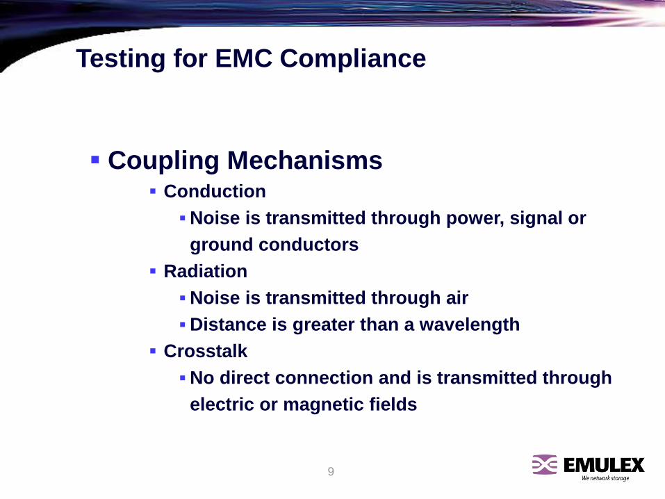
▪ Coupling Mechanisms▪ Conduction
▪ Noise is transmitted through power, signal or
ground conductors
▪ Radiation
▪ Noise is transmitted through air
▪ Distance is greater than a wavelength
▪ Crosstalk
▪ No direct connection and is transmitted through
electric or magnetic fields

10
Testing for EMC Compliance
▪ Solutions
▪ PCB Design
▪ Filtering
▪ Cabling/Harnessing
▪ Grounding/Bonding
▪ Shielding

11
Testing for EMC Compliance
The Physics of it All
MAXWELL EQUATIONS
▪ Forms the building blocks of understanding the electromagnetic phenomena.
▪ Gauss’s Law - There are + and - electric charges and no magnetic charges.
▪ Faraday’s Law - A changing magnetic field cutting across a closed loop generates a current flow.
▪ Ampere’s Law - A current flow creates a magnetic field.

12
Testing for EMC Compliance
▪ A time varying electric field between two conductors can be represented as a capacitor.
▪ A time varying magnetic field between two conductors can be represented by mutual inductance.
AN RF VOLTAGE POTENTIAL WILL CAUSE A TIME VARYING CURRENT GENERATING A TIME VARYING MAGNETIC FIELD
WHICH, IN TURN, DEVELOPES A TIME VARYING TRANSVERSE ELECTRIC FIELD. THIS IS AN ELECTROMAGNETIC FIELD.
MAXWELL EQUATIONS (cont.)

13
Testing for EMC Compliance
Fault Isolating
Be like a Doctor
▪ Diagnose First
▪ Gather information
▪Ask questions
▪ Make preliminary diagnosis
▪Eliminate least likely
▪Determine the most likely
▪ Often times initial fixes won’t work
▪ There could be multiple contributors

14
Testing for EMC Compliance
Key Questions
▪ What are the symptoms?
▪ Equipment issues
▪What is the problem?
▪When was it first noticed?
▪What else is wrong?
▪ What are the likely causes?
▪ Environmental issues?
▪ ESD?
▪ Power disturbances?

15
Testing for EMC Compliance
Key Questions (continued)
▪ What are the constraints?
▪ System issues
▪ Cost?
▪Cost of failure not just cost of component
▪ Board modifications?
▪ How will you know if it is fixed?
▪ Establish a goal
▪ Method of verification

16
Testing for EMC Compliance
Specific Questions for Emission Problems
▪ What is the frequency of the noise?
▪ Is it continuous or intermittent?
▪ Does the noise happen in relation to another event such as when a printer is printing or data is transferring?
▪ Is it cable or enclosure ?

17
Testing for EMC Compliance
Specific Questions for Immunity Problems
▪ What is the error or fault that is observed?
▪ Is it cable or enclosure related?
▪ Is it a radiated or conducted effect?
▪ Isolate circuitry or subassemblies

18
Testing for EMC Compliance
Perform EMCscan
ResultsIssue certificatePass Fail
Remove external cables
except power cables
FailResults
Pass
Investigatecable
assemblies
TROUBLESHOOTINGSECTION
COMPLIANCESECTION
InvestigatePCB layoutand cable
interconnects
Install ferriteclamp(s) on I/O
Replace I/Owith shielded
version
Separatecables fromeach other
Replacecables
Install ferriteclamp on ACpower cord(s)
Install ACline filter
ResultsPass
End
Fail
End
Fail
Investigateenclosure
Determineif broadband,narrowbandor ambient
Improveshielding ofenclosure
ResultsPass
End
ResultsPass
Fail
End
Ambient
Fail
Figure 8.4 Flow chart for emissions testing and troubleshooting.

19
Testing for EMC Compliance
continuous
radiated conducted
Continuous
intermittent?
What changed?
Switch devices on/off/on
one at a time.
Identify and define problem
What happened? What is affected?
Visual InspectionLine filter
Grounding of equipmentGrounding of cable shields
Types of I/O cables
Radiatedor
Conducted
Perform measurements
(Antennas and
spectrum analyzer, near field probes)
Perform measurements
(Oscilloscope, current probe, voltage probe)
Simulate Problem
Resolve problem
Frequency involved?When did it begin to happen?
What changed?
What time of the day or week
does the problem occur?
intermittentor
Figure 8.5 Systematic approach to detecting and locating problems

20
Testing for EMC Compliance
Perform a Visual Inspection
Many times a visual inspection can lead to a starting point.
▪ Are there unclosed seams or openings?
▪ Are the cables shielded or filtered?
▪ Are the cable connectors good?
▪ What is the grounding scheme?
▪ Is the circuit board multilayer?
▪ Are internal cables placed for minimizing coupling?

21
Testing for EMC Compliance
Board Fixes
▪ Circuit board “changes” are most appropriate early in the design stage.
▪ Circuit board “fixes” are most appropriate when you cannot re-lay the board.

22
Testing for EMC Compliance
Outside the Box
▪ Disconnect cables and peripheral devices
▪ Use ferrites or aluminum foil for cables that cannot be disconnected
▪ Start with a “minimum configuration” system
▪ One at a time, re-connect cables and peripherals and solve individually

23
Testing for EMC Compliance
Inside the Box
If enclosure fixes are unacceptable, then turn to inside the box.
–Check cable routing
–Check grounding
–Circuit board

24
Testing for EMC Compliance
Techniques for Emissions▪ “Piece of wire” or a screwdriver
▪ Current clamp
▪ Current magnitude and direction
▪ “Directionality” of current flow
▪ Measure cable, Icm1, and second cable, Icm2, individually and then together (Icm1 + Icm2)
▪ If (Icm1 + Icm2) is greater than either individually, then it is crosstalk
▪ If (Icm1 + Icm2) is less than either individually, then it is common impedance
▪ DM or CM ?
▪ CM
▪ Line-to-ground capacitors
▪ Common mode inductors
▪ For I/O cables, 5 uA max for Class B and 15 uA max for Class A
▪ DM
▪ Line-to-line capacitors
▪ Series inductors

25
Testing for EMC Compliance
Using current clamps for “directionality”

26
Testing for EMC Compliance
Techniques for Emissions (cont.)
▪ Radiated emissions below 200-300 MHz are typically cable related, while above this frequency, it is usually box related.
▪ Near Field Probes
▪ Slots, seams
▪ PCB traces
▪ Oscilloscope with differential probe
▪ Ground noise / Cable noise
▪ IC Noise / Power Supply Noise
▪ Use AM/FM radio as in inexpensive EMI/ESD sniffer

27
Testing for EMC Compliance
(Photo courtesy of Agilent)
(Photo courtesy of EMC Test, Inc.)

28
Testing for EMC Compliance
(Photo courtesy of EMC Compliance Journal)

29
Testing for EMC Compliance
Techniques for Immunity▪ Hand-held VHF/UHF radios
▪ “Chattering relay”
▪ Wired in a self oscillating mode
▪ Small loop
▪ Signal generator & 1-5 W amplifier
▪ Signal Injection
▪ ESD Gun
▪ Can simulate ESD, EFT, RI
▪ A Capacitive Clamp
▪ 50 cm of foil around cable (100pF)

30
Testing for EMC Compliance
Techniques for Immunity (cont.)
▪ Current Injection Probe
▪ About 10 watts is good for 1-3 volts
▪ Use a Bias-Tee Network or a capacitor
▪ Use EFT generator or ESD generator to simulate power bus noise problems
▪ Couple through a capacitor of about 0.01 or 0.001 uf
▪ Can simulate “hot swap” noise problems

31
Testing for EMC Compliance
N/C
C
N/O
“Noise Loop”
“Chattering Relay”

32
Testing for EMC Compliance
Minimal Requirement for Lab Setup▪ As quiet an ambient as possible
▪ Noise-free power main
▪ Ground plane (reference for power)
▪ Test Equipment

33
Testing for EMC Compliance
Test Equipment▪ Spectrum analyzer/receiver
▪ Balanced differential probe
▪ Current probe
▪ Near field probes
▪ LISN
▪ ESD simulator
▪ Signal generator
▪ Low Level Power Amplifier
▪ Hand-held radios
▪ Network analyzer
▪ Correlation analyzer

34
Testing for EMC Compliance
Typical Sequence of Testing▪ Locate PCB “hot spots”
▪ Near-field probes
▪ Emissions measurement of open PCB
▪ If emissions are less than SE of enclosure, then PCB will likely be okay
▪ Shielding effectiveness (SE) of enclosure
▪ Make a battery operated oscillator
▪ Put inside the enclosure
▪ Measure amplitudes and re-measure without the enclosure
▪ Analyze leakages in the enclosure
▪ Common Mode Cable Currents

35
Testing for EMC Compliance

36
Testing for EMC Compliance
“Bag of Quick Fixes”▪ Aluminum foil
▪ Conductive tape and gaskets
▪ Braid and “zippertubing”
▪ Ferrites
▪ Power line filters
▪ Components
▪ Small capacitors
▪ Resistors
▪ Inductors

37
Testing for EMC Compliance
“Bag of Concept Tricks”▪ For an electromagnetic problem, the distance must be
greater than a wavelength away
▪ Inductive coupling is caused by di/dt and low impedance circuits
▪ Induced noise is in series
▪ Electric field coupling is caused by dv/dt and high impedance circuits
▪ Induced noise current is in parallel
▪ Disconnect load
▪ If problem still persists, then it is voltage related and possibly capacitive coupled
▪ If problem goes away, then it is current related and possibly inductive coupled

38
Testing for EMC Compliance
Current probe (magnetic field)
EUTLISN
Current probe
Auxiliary Unit
Receiver
Peripheral
Current probe
Near field probes(electric and magnetic)
(magnetic field)
(magnetic field)
dB A or dB V (volage probe)
Alternate RE testing setup

39
Testing for EMC Compliance
1. Clamp probe around the cable and measure the amplitude of theharmonic in question
2. Convert to current: I (dBuA) = V (dBuV) – ZT (dBW)3. Plug into emission equation:
E (V/m) = 1.26x10⁻⁶(f L I) / R
where f is in Hertz, L is cable length in meters,I is in amperes and R is in meters
L is either actual length or maximum of c/4f

40
Testing for EMC Compliance
EXAMPLE
1. Measured 33.5 dBuV on the analyzer at 100 MHz of a 5 meter cable2. Convert to current: I (dBuA) = 33.5dBuV – 15dBW = 18.5 dBuA3. Plug into emission equation:
L = c / 4(100MHz) = 0.75 metersI = 8.4 uA
E (V/m) = 1.26x10⁻⁶(f L I) / R
= 2.65 x 10⁻⁴ V/m= 48.5 dBuV/m
For FCC Class B at 100 MHz measured at 3 meters, the limit is 43.5 dBuV/m. We are potentially 5 dB over. Notice that it doesn’t takemuch current to exceed the limit.

41
Testing for EMC Compliance
(Photograph courtesy of Cortland Richmond)

42
Testing for EMC Compliance
Correlation analyzer (Photo courtesy of SARA Inc.)
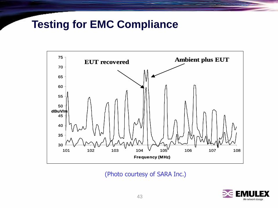
43
Testing for EMC Compliance
(Photo courtesy of SARA Inc.)
30
35
40
45
50
55
60
65
70
75
101 102 103 104 105 106 107 108
Frequency (MHz)
dBuV/m
Ambient plus EUTEUT recovered
30
35
40
45
50
55
60
65
70
75
101 102 103 104 105 106 107 108
Frequency (MHz)
dBuV/m
Ambient plus EUTEUT recovered

44
Testing for EMC Compliance
(Courtesy of SARA Inc.)
Source 1

45
Testing for EMC Compliance
(Courtesy of SARA Inc.)
Source 2

46
Testing for EMC Compliance
(Courtesy of SARA Inc.)
Source 3

47
Testing for EMC Compliance
Leave all the fixes in place no matter what the effect.
Solve the problem.
THEN remove fixes one at a time.