testing and verification protocol for engine and vehicle ... · 570, boul. saint-jean pointe claire...
TRANSCRIPT

570, boul. Saint-Jean Pointe-Claire (Qc) H9R 3J9 www.pit.fpinnovations.ca
Testing and Verification
Protocol for Engine and
Vehicle After-market
Devices

THIS PAGE INTENTIONALLY LEFT BLANK

Testing and Verification
Protocol for Engine and
Vehicle After-market Devices
March 28, 2013
© Copyright 2013, FPInnovations

THIS PAGE INTENTIONALLY LEFT BLANK
i Testing and Verification Protocol for EAMDs
Table of contents SUMMARY ......................................................................................................................................................................... 1
INTRODUCTION .................................................................................................................................................................. 3
CONTEXT ................................................................................................................................................................................... 3 PROTOCOL DEVELOPMENT PROCESS .............................................................................................................................................. 3 OBJECTIVES ................................................................................................................................................................................ 4 PROTOCOL OUTLINE .................................................................................................................................................................... 4
TESTING AND VERIFICATION PROTOCOL ........................................................................................................................... 7
1. SCREENING OF THE APPLICATION .......................................................................................................................................... 7 1.1. Self-assessment Pre-screening Application ............................................................................................................... 8 1.2. Screening .................................................................................................................................................................... 8
2. TESTING OF TECHNOLOGY TO EVALUATE PERFORMANCE ........................................................................................................ 11 2.1 Canadian ETV Program General Test Protocol ......................................................................................................... 11 2.2. Performance Parameters ......................................................................................................................................... 11 2.3 Test Methods ............................................................................................................................................................. 16 2.4. Test Report................................................................................................................................................................ 25
3. VERIFICATION .................................................................................................................................................................. 27
DISCUSSION AND RECOMMENDATIONS ......................................................................................................................... 29
CONCLUSIONS .................................................................................................................................................................. 29
ACKNOWLEDGEMENTS .................................................................................................................................................... 30
REFERENCES ..................................................................................................................................................................... 31
APPENDIX A. TECHNICAL ADVISORY COMMITTEE ........................................................................................................... 33
APPENDIX B. SUMMARY OF EXISTING TESTING AND VERIFICATION PROTOCOLS .......................................................... 35
APPENDIX C. SELF-ASSESSMENT APPLICATION FORM .................................................................................................... 37
APPENDIX D. PERFORMANCE CRITERIA FOR TIRES.......................................................................................................... 41
APPENDIX E. TEST CONDITIONS FOR PEMS EMISSIONS FIELD TESTING .......................................................................... 43
ii Testing and Verification Protocol for EAMDs
List of Figures
Figure 1. Screening process. .................................................................................................................................... 7 Figure 2. Two-cycles and Five-cycles fuel consumption test diagrams (from Transport Canada 2011). ............ 21 Figure 3. ETV Canada verification process (from Environment Canada 2012). ................................................... 27 Figure 4. Performance criteria for low rolling resistance tires (from EPA 2011a). .............................................. 41 Figure 5. Performance criteria for retread tires (adapted from EPA 2011b). ...................................................... 41
List of Tables
Table 1. Proposed guidelines for screening ............................................................................................................. 9 Table 2. GHG emission factors for heavy-duty diesel vehicles ............................................................................. 12 Table 3. Proposed testing methods according to the tested technology ............................................................ 16 Table 4. Technical advisory committee ................................................................................................................. 33 Table 5. Summary of existing testing and verification protocols ......................................................................... 35 Table 6. Test conditions for PEMS emissions field testing .................................................................................... 43

1 Testing and Verification Protocol for EAMDs
Summary
Environmental quality and energy efficiency are priority areas for Environment Canada. Environment Canada manages Canadian Environmental Technology Verification (ETV) Program, which offers independent verification of environmental performance claims for innovative technologies, processes, and products.
The challenges and opportunities presented by engine and vehicle after-market devices is a specific technology area of interest to a range of stakeholders.
This testing and verification protocol helps guide the demonstration and deployment of effective engine and vehicle technologies and solutions. The protocol meets the requirements of the Canadian ETV Program and the program’s General Verification Protocol.
In consultation with Environment Canada and the Canadian ETV Program’s delivery agent, GLOBE Performance Solutions, a Technical Advisory Committee (TAC) was formed to engage sectorial stakeholders, experts and municipalities in a round table discussion leading to the development of a suitable testing and verification protocol for engine and vehicle after-market devices. The TAC provided input and technical expertise into the development of this technology testing and verification protocol.
The following generic process is proposed:
Screening of the application: the objective is to determine if the technology meets basic requirements prior to proceeding with performance testing and verification;
Testing of technology to evaluate performance: the focus of testing is to determine, with a 95% level of confidence, the statistical significance of changes in the fuel consumption and/or emissions of the engine or of the vehicle on which the tested technology is used;
Verification of the test report: the verification process is a third party expert evaluation of the technology and of the independent third party testing based on the requirements of the Canadian ETV Program General Verification Protocol.
This protocol presents the general test methodology and existing test methods that can be used for engine and vehicle after-market devices, with reference to applicable standards and regulations, and in a manner that is consistent with the framework of the Canadian ETV Program General Test Protocol.
Considering that specific regulations and standards are already in place across a number of jurisdictions, the protocol does not detail test procedures. However, because unique technologies may require specific test plans that cannot be found in existing standards, particular testing methods may be accepted, depending on the equipment covered by the application.
It is recognized that the while the process must be accurate, it must also be cost effective to facilitate technology supplier access to verification.

THIS PAGE INTENTIONALLY LEFT BLANK

3 Testing and Verification Protocol for EAMDs
Introduction
Context
Environment Canada’s ETV Program is based on sound science, high-quality data, and recognized protocols. The Program offers independent verification of environmental performance claims for innovative technologies, processes, and products. According to Environment Canada (2012a), for the purposes of the ETV Program, environmental technologies are products and processes that offer an environmental benefit or address an environmental problem. This definition includes products and processes whose primary purpose is environmental protection or remediation. It also includes products or processes that contribute to environmentally sound production, including alternative production processes and materials.
Fuel costs continue to escalate and "green" transportation technologies are increasingly in demand. Obstacles to the adoption of innovative technologies include the lack of credible information from independent qualified sources. Therefore, one of the ways to support the industry is to provide reliable information resulting from the rigorous testing of fuel-efficient and emissions technologies, and to present this information to key stakeholders in the transportation, fleet and freight sectors.
The challenges and opportunities presented by engine and vehicle after-market devices (EAMDs) is a specific technology area of interest to a range of stakeholders.
Previous work has assessed the need and characterized the scope for the independent performance verification of vendor claims related to energy and emissions improvements. A general EAMD draft protocol was developed (ETV Canada – OCETA 2007), and a study was completed in 2010 for Transport Canada, Natural Resources Canada and Environment Canada indicating the size of this market and the range of technologies being promoted (OCETA 2010).
Protocol Development Process
In consultation with Environment Canada and the Canadian ETV Program’s delivery agent, GLOBE Performance Solutions, a Technical Advisory Committee (TAC) was formed, to engage sectorial stakeholders, experts and municipalities in a round table discussion leading to the development of a suitable testing and verification protocol for engine and vehicle after-market devices. The TAC provided input and technical expertise into the development of the testing and verification protocol. Appendix A presents the composition of the TAC.
The first stage of the protocol development process was to present a background document to TAC members for analysis. The background document presented:
An analysis of existing test methods and verification protocols for engine and vehicle after-market devices, including a review of the Canadian ETV Program General Test Protocol and the General Verification Protocol (GVP);
A tabular summary of a comparative analysis of existing testing and verification protocols for engine and vehicle after-market devices (Appendix B);
A proposed set of screening and evaluation parameters, and testing and verification protocols.

4 Testing and Verification Protocol for EAMDs
Based on the feedback received from the first TAC meeting, screening and evaluation parameters and testing and verification protocols were revised, and a complete draft protocol was consequently presented for review. The feedback received during the second TAC meeting allowed to refine and finalize the protocol.
Objectives
This protocol aims to guide and support the review and approval of performance verification claims by any manufacturer or vendor of EAMDs in a transparent and credible manner.
The protocol aims to be mutually acceptable to both technology users and proponents so that valid and credible data is in place to support performance claims: acceptable for technology users means accurate and independent results, while proponent looks for credibility at the lowest cost.
Protocol Outline
The protocol meets the requirements of the Canadian ETV Program and the program’s General Verification Protocol (Environment Canada 2012a), such as:
o Overall guidance through a General Verification Protocol;
o Quality-assured test procedures and analytical techniques to measure performance parameters;
o Testing and analysis by an independent third-party test agent;
o Verification and report by an independent verification organization.
A generic verification process, outlined below, is proposed.
Screening of the application
o The scope is to determine if technology meets basic requirements prior to proceeding with performance testing and verification.
o The first stage is an initial self-assessment pre-screening application, common for all the components of the Canadian ETV Program.
o The second screening consists of a technical review of the documentation by a qualified independent expert, or a committee of independent experts.
Testing of technology to evaluate performance
o This protocol presents the general test methodology and existing test methods that can be used, with reference to applicable standards and regulations, in a manner that is consistent with the framework of the General Test Protocol. Considering that specific regulations and standards are already in place across a number of jurisdictions, the protocol does not detail test procedures.
o However, because unique technologies may require specific test plans that cannot be found in existing standards, and depending on the equipment covered by the application, particular testing methods may be accepted by the expert or committee of experts reviewing the application. For some particular technologies, the protocol specifies test procedures, such as testing on duty cycles, testing of refrigeration units, and testing of idle reduction technologies.
5 Testing and Verification Protocol for EAMDs
o The focus of testing is to determine, with a confidence level of 95%, the statistical significance of changes in the fuel consumption and/or emissions of the engine, equipment or vehicle on which the tested technology is used, according to the specific performance parameter.
o The nominal values for the changes in the fuel consumption and/or emissions are determined from the analysis of the measured fuel or emission data and reflect the changes resulting from the modification being tested on the test vehicle, engine, or equipment. The confidence interval must be less than the nominal result for having a statistically valid result.
Verification of the test report
o The verification process is based on the General Verification Protocol..
o The verification organization must be an independent third party organization.
Life cycle analysis (LCA) is not the objective of this protocol: verification can only be applied against measurable performance criteria. LCA is an important decision-making tool, but environmental performance verification of technologies based on a full-range of comprehensive systemic parameters would be extremely difficult to implement.
Cost analysis is not an exclusory stage of the process, but it provides additional information to the user of the technology under consideration.

THIS PAGE INTENTIONALLY LEFT BLANK

7 Testing and Verification Protocol for EAMDs
Testing and Verification Protocol
1. Screening of the Application
The proposed screening process is presented in Figure 1 (based on OCETA 2010 and Canadian ETV 2012).
Figure 1. Screening process.
8 Testing and Verification Protocol for EAMDs
1.1. Self-assessment Pre-screening Application
If the applicant considers that his/her technology meets the following requirements, he/she submits an Online Screening Form (Appendix C), common for all the components of the Canadian ETV Program:
It must be an environmental technology as defined by the General Verification Protocol (Environment Canada 2012a);
The performance claim must meet minimum Canadian standards and/or national guidelines for that technology and where it is being used;
The performance claim must be measurable;
The applicant must own the intellectual property of the technology to be verified, or can obtain a written permission from the owners to pursue the verification; and
The technology must be currently commercially available or commercially ready for full-scale application.
The technology undergoes a preliminary screening to determine if it meets minimum eligibility requirements for verification.
If the technology meets the minimum eligibility requirements for verification, the applicant submits a Formal Application (according to the general procedure of the Canadian ETV Program).
1.2. Screening
With the Formal Application, the applicant must provide (Canadian ETV 2012):
An original signed letter attesting to the applicant’s ownership of the intellectual property of the technology to be verified or, if the applicant is an authorized user, manufacturer or distributor(rights-holder), an original letter from the owner attesting to the existence of a licensing or similar agreement in force as of the date of formal application;
Information to support the verification, including more detailed technology data, the claim to be verified, and the data and information to support the claim.
The delivery agent of the Canadian ETV program reviews the Formal Application for completeness and determines if the technology can proceed further.
The screening method involves a technical review of the documentation by a qualified independent expert, or a committee of independent experts, from or nominated by the delivery agent. If the delivery agent lacks particular expertise, outside experts can be used.
Five key screening areas were identified (OCETA 2010):
1. Company or vendor status
2. Technology
3. Product details
4. Potential environmental impacts
5. Existing test results

9 Testing and Verification Protocol for EAMDs
Table 1 presents guidelines to help the experts in the evaluation of the applications in a uniform manner (based on OCETA 2010).
Table 1. Proposed guidelines for screening
Company or vendor status
Reputation1
Relevant business experience in the sector
Experience with the specific technology or similar designs
Technology
Description
Applicability
Customers
How technology works
Installation, operating criteria and constraints
Patents
Technical papers
Product
Performance claim and basis for performance claim
Potential unique testing needs
Health effects and safety data (MSDS or EPA registered if available)
Compatibility with OEM equipment
Impact on original warranty
Liability insurance coverage
Environmental impact
Meeting applicable regulations and standards
Disposal
No hazardous or toxic effects
Does not increase emissions
Existing test results
Preliminary test results for fuel savings or GHG emission reduction
Preliminary test results for emission of pollutants reduction
Test data generated by third party
Test data not older than 3 years
(Make sure that test data are for the current technology)
Level 1 Level 2
1 The applicant has not been found responsible for or guilty of violations of the law.

10 Testing and Verification Protocol for EAMDs
If the application passes the screening, the delivery agent discusses the method of verification with the applicant, which could be either:
Using existing test data, if the data are generated by third party, no older than three years, and meet the quality requirements outlined in the Application Guide, or
Working with a third party test agent to develop an appropriate testing plan and generate data as per the test plan.
Note that technical experts may be consulted as part of this process.

11 Testing and Verification Protocol for EAMDs
2. Testing of Technology to Evaluate Performance
2.1 Canadian ETV Program General Test Protocol
The General Test Protocol (GTP) provides guidance to vendors and testing agencies for:
Developing and executing a test program to assess the performance of an environmental technology;
Preparing a report that summarizes the test results in support of an application to the ETV Program for performance claim verification.
The protocol has been structured according to a four-step process to facilitate the collection of sound data for claim verification (Environment Canada 1998):
1. Design of test program
Test agency develops a draft experimental plan with the vendor.
Draft plan submitted to the delivery agent for review.
Delivery agent revises and acknowledges the plan.
Test agency proceeds with implementation of the plan.
2. Data collection: performance parameters and operating conditions
3. Data assessment: based on the principles of relevance and quality
4. Reporting the results.
2.2. Performance Parameters
2.2.1 Emissions of pollutants and GHG
a) For pollutant emissions, it is recommended to measure the regulated pollutants (according to Canadian or EPA regulations), such as carbon monoxide (CO), nitrogen oxides (NOx), non-methane hydrocarbons (NMHC), and particulate matters (PM). For comparative technology evaluation purposes, the measurement of PM emissions is not required for vehicles complying with EPA 2007 emission requirements or later, considering the very high efficacy of particulate filters, and the extremely low PM emissions level of these vehicles. This exclusion does not apply for the technologies intended to reduce PM emission. Total hydrocarbons (THC) can be measured instead of NMHC, according to EPA requirements and stipulations (for heavy-duty diesel vehicles, for example, subtract two percent from the measured THC value to obtain an NMHC value).
b) For greenhouse gas (GHG) emissions, it is recommended to measure carbon dioxide (CO2), methane (CH4), and nitrous oxide (N2O). However, Table 2 (Environment Canada 2012b) shows that for diesel and gasoline engines CH4 and N2O emissions are negligible in comparison to CO2
emissions, thus only the CO2 emission reduction can be used for comparative evaluation purposes for these types of engines. For natural gas vehicles, it is imperative to measure CO2, CH4, and N2O.

12 Testing and Verification Protocol for EAMDs
Table 2. GHG emission factors for heavy-duty diesel vehicles
Type of engine control system Emission factor (g/L of fuel)
CO2 CH4 N2O
Diesel Heavy-duty Advanced Control 2 663 0.11 0.151
Diesel Light-duty Advanced Control 2 663 0.068 0.22
Diesel Off-road 2 663 0.15 1.1
Gasoline Light-duty Tier 2 2 289 0.14 0.022
Gasoline Off-road 2 289 2.7 0.05
c) The focus of testing is to determine, with a confidence level of 95%, the statistical significance of the reduction in emissions of the vehicle or engine, on which the tested technology is used. The nominal values for the changes in emissions are determined from the analysis of the measured emission data and reflect the reductions resulting from the modification being tested on the test vehicle or engine.
d) The performance criteria is the percentage improvement (decrease of emissions) over the baseline correlated with the baseline absolute values, which means that the percentage improvement must be presented in the context of the baseline value. For example a reduction in NOx from 0.11 to 0.10 g/bhp-hr is a reduction of 9%, but is practically minor in the context of the baseline value, which is already very low and the variation in testing conditions and results.
e) Emission tests are conducted on a vehicle (engine, equipment) representative of the typical vehicle (engine, equipment) for which the technology is intended.
f) At least three baseline segment tests without the technology followed by three final segment tests with the technology fitted would be the minimum acceptable in both laboratory and track (road) tests.
g) The result is expressed as a nominal value plus and minus the confidence interval. If the confidence interval value for a test is greater than or equal to the nominal test value, as determined by the statistical analysis results, it is recommended that additional tests be conducted to reduce the confidence interval value to less than nominal test value. For example, if the nominal value of the tests result is 3% and the confidence interval is 4%, the results is expressed as 3% ±4%. In this example additional tests must be conducted to lower the confidence interval. If additional tests do not show statistically conclusive results, the conclusion must be that the test does not show a statistically valid change in emissions (the change is less than the test precision, or the change in emissions is influenced by variations in the test conditions).
h) The device manufacturer is responsible for meeting emissions and diagnostic standards (OBD compliance). Technologies intended to reduce the emission of pollutants must not increase fuel consumption or GHG emissions, which include CO2, CH4, and N2O. However, for diesel and gasoline engines only the CO2 emissions can be measured for comparative evaluation purposes. Technologies intended to reduce the GHG emissions must not increase regulated emissions, which include CO, NOx, NMHC, and PM. The measurement of PM emissions is not required for vehicles complying with EPA 2007 emission requirements or later, considering the very high efficacy of particulate filters, and the extremely low PM emissions level of these vehicles.

13 Testing and Verification Protocol for EAMDs
i) For technologies intended to reduce the emission of pollutants, which are installed on an engine
and its auxiliary systems exhaust system, antipollution system, air intake, fuel delivery system
etc. durability testing is recommended to verify performance over time. Once the technology is verified and 500 units are sold, the applicant is responsible for reporting to the delivery agent of the Verification Program. The delivery agent will analyze and decide on the necessity and opportunity of developing an appropriate test plan (experts can be consulted in this process). In the case of regulated technologies and devices, such as catalytic convertors, exhaust gas recirculation system components, and selective catalytic reduction systems components, the durability testing stipulated by the applicable regulations or standards must be conducted.
2.2.2 Fuel Efficiency
a) The focus of testing is to determine, with a confidence level of 95%, the statistical significance of changes in the fuel consumption of the vehicle, engine, or equipment, on which the tested technology is used. The nominal values for the changes in fuel consumption are determined from the analysis of the measured fuel data and reflect the fuel consumption reduction resulting from the modification being tested on the test vehicle, engine, or equipment.
b) Fuel consumption tests are conducted on a vehicle (engine, equipment) representative of the typical vehicle (engine, equipment) for which the technology is intended.
c) At least three tests without the fuel saving technology (baseline segment), followed by three tests with the fuel saving technology installed on the test vehicle (final segment) would be the minimum acceptable in both laboratory and track (road) tests.
d) The proposed performance criterion is the achievement of fuel savings of 3% (minimum nominal value) over the baseline.
e) The result is expressed as a nominal value plus and minus the confidence interval. If the confidence interval value for a test is greater than or equal to the nominal test value, as determined by the statistical analysis results, it is recommended that additional tests be conducted to reduce the confidence interval value to less than nominal test value. For example, if the nominal value of the tests result is 3% and confidence interval is 4%, the results is expressed as 3% ±4%. In this example, additional tests must be conducted to decrease the confidence interval. If additional tests do not show statistically conclusive results, the conclusion must be that the test does not show a statistically valid change in fuel consumption (the change is less than the test precision, or the change in fuel consumption is influenced by variations in the test conditions).
f) The technology manufacturer is responsible for meeting emissions and diagnostic standards (OBD compliance). The fuel-saving technology must not increase regulated emissions, which include CO, NOx, NMHC, and PM. The measurement of PM emissions is not required for vehicles complying with EPA 2007 emission requirements or later, considering the very high efficacy of particulate filters, and the extremely low PM emissions level of these vehicles.

14 Testing and Verification Protocol for EAMDs
2.2.3 Indirect Parameters and Criteria for Evaluating the Impact on Fuel Efficiency or GHG Emissions
For some verification processes, indirect parameters and criteria for evaluating the impact of a technology on fuel efficiency or GHG emissions can be accepted.
a) For technologies intended to reduce rolling resistance, the performance parameter is the rolling resistance coefficient.
i. Each 3% decrease in rolling resistance could improve fuel efficiency by as much as 1%, according to tire manufacturers2. According to the GHG Emissions Standards and Fuel Efficiency Standards for Medium- and Heavy-Duty Engines and Vehicles (EPA and NHTSA 2011), a 10% reduction in tire rolling resistance would reflect fuel savings of 2%.
ii. The proposed performance criterion is a 10% reduction (minimum) of the rolling resistance coefficient over the baseline average value.
iii. At least three rolling resistance tests with conventional tires (baseline segment), followed by three tests with the low rolling resistance tires (final segment) would be the minimum acceptable in laboratory tests.
b) For technologies intended to reduce aerodynamic drag, the performance parameter is the wind averaged coefficient.
i. Each 2% decrease in aerodynamic drag could improve fuel efficiency by as much as 1%, according to Kenworth (2008) and based on dynamic equations (Surcel et al. 2008).
ii. The proposed performance criterion is a reduction of 6% (minimum) of the wind averaged coefficient of drag over the baseline average value.
iii. At least three tests without the aerodynamic technology or modification (baseline segment), followed by three tests with the aerodynamic technology or modification applied to the test vehicle or test vehicle model (final segment) would be the minimum acceptable in wind tunnel tests.
c) For technologies intended to reduce vehicle tare weight, such as lighter van boxes or body components, the performance parameter is relative mass reduction compared to the original configuration.
i. Dynamic equations show that for a Class 8 tractor-semitrailer combination with gross vehicle mass of 30,000 kg, a mass reduction of 1,500 kg (5% of the gross vehicle mass, and 12% of the tare mass) could reflect a 4% fuel consumption reduction for the loaded vehicle.
ii. The proposed performance criterion is a reduction of a minimum of 9% of the tare mass of the vehicle in its normal operating configuration. For example, for the mass reduction of a tractor or a semi-trailer, the normal operating configuration is the tractor-semi-trailer combination. Other constructive parameters of the vehicle, such as aerodynamic performances, or rolling resistance, must not be negatively affected.
2 http://www.michelintruck.com/michelintruck/tires-retreads/xone/xOne-fuel-savings.jsp
15 Testing and Verification Protocol for EAMDs
d) For evaluating the impact of a technology on GHG emissions, an indirect performance parameter is the reduction of fuel consumption. The CO2 equivalent GHG emission factor can be calculated, using the equivalent GHG potential of 298 times for nitrous oxide, and of 25 for methane compared to that of carbon dioxide on a per unit mass basis (IPCC 2007), with equation (1):
(1)
For example, using equation (1) and the values presented in Table 2, the CO2 equivalent GHG emission factors are:
i. For diesel engines with advanced engine control systems (i.e., the majority): 2.71 kg CO2 equivalent per litre of diesel fuel;
ii. For gasoline light-duty, Tier II engines the CO2: 2.30 kg CO2 equivalent per litre of diesel fuel.

16 Testing and Verification Protocol for EAMDs
2.3 Test Methods
2.3.1 Proposed Testing Methods
The goal of technology verification is to accelerate technology implementation by providing credible data to fleet managers. This is why fuel consumption track testing is a test method preferred by many organizations, such as EPA SmartWay and MTQ, and it is used for evaluating various technologies, like aerodynamic devices, rolling resistance reduction technologies, and technologies for improving powertrain efficiency. Track testing directly measures the fuel consumption in real conditions, which is what the user wants. Track tests are critical to establish the potential of a technology for fleet operators interested in pursuing the implementation of any technologies, and from the point of view of the impact on fuel consumption the final validation should be a track test. Experience with fleets shows that the chances are very small that a technology is adopted solely on the basis of simulation or wind tunnel test results.
Table 3 presents the proposed testing methods according to the tested technology.
Table 3. Proposed testing methods according to the tested technology
Technology Performance target Test method Performance
parameter
Aerodynamic technologies
Fuel efficiency Fuel consumption track test Fuel savings
Aerodynamic drag reduction
Wind tunnel test (full scale vehicle or a high fidelity detailed 1/8 scale or larger model)
Cdw reduction
Standardized or regulated procedures using CFD simulations
Cdw reduction
Rolling resistance technologies
Fuel efficiency Fuel consumption track test Fuel savings
Rolling resistance reduction Rolling resistance tests RR coefficient reduction
Technologies for powertrain, and auxiliary systems ( exhaust system, antipollution system, air intake, fuel delivery system etc.)
Fuel efficiency
Chassis dynamometer test Fuel savings
Engine dynamometer test Fuel savings
Fuel consumption track tests or field test Fuel savings
Emissions
Chassis dynamometer test Emissions reduction
Engine dynamometer test Emissions reduction
Emissions track tests or field test Emissions reduction
Mass reduction technologies
Mass reduction Weighing Mass reduction
Fuel efficiency Fuel consumption track test Fuel savings
Other technologies (idle reduction, heaters, APUs, reefer etc.)
Fuel efficiency Custom test Fuel saving
Emissions Custom test Emissions reduction

17 Testing and Verification Protocol for EAMDs
2.3.2 Emission Test Methods
2.3.2.1 Engine Dynamometer Testing
The accepted test methods are (as amended from time to time):
a) Highway engine dynamometer tests: according to the Federal Test Procedure (FTP) Transient Test and Smoke Test Procedures, such as 40 CFR Part 86 (for older engines), and Part 1065 for heavy-duty highway engines, including both diesel and Otto-cycle engines (for 2010 and later model years);
b) Non-road engines: according the applicable non-road FTP test cycle, such as for Tier 1, 2, and 3 standards, using the procedures in 40 Code of Federal Regulations (CFR) Part 89 Subpart E, California Regulations for New 1996 and Later Heavy-Duty Off-Road Diesel Cycle Engines. For Tier 4 standards, engines are tested for transient and steady-state exhaust emissions using the procedures in 40 CFR Part 1039 Subpart F; Smoke emissions according to 40 CFR Part 86 Subpart I; 40 CFR Part 1048 for Spark Ignition engines etc.;
c) Other recognized standard or regulation test procedures and particular test methods could be accepted;
d) A mobile (portable) emission measurement system can be used for laboratory testing according to EPA Title 40 Part 1065 – Subpart J PEMS testing, §1065.901;
e) Test conditions (ambient temperature, humidity, test equipment specification, including accuracy and precision of instruments and equipment, etc.) according to the applicable test procedure. If a particular test method is developed, the requirements of similar standards or regulations must be met, such as 40 CFR Part 1065.
2.3.2.2 Chassis Dynamometer Testing
The accepted test methods are listed below.
a) Light duty vehicles
i. Testing according to the Federal Test Procedure (FTP), such as 40 CFR Part 86, and Part 1065, FTP 72, FTP 75, or SAE J1082 (SAE International 2008)
ii. Test cycles such as:
Urban Dynamometer Driving Schedule (UDDS);
US SC03 (test cycle operating the air conditioning system);
US 06 (SFTP, aggressive driving cycle);LA92 "Unified" Dynamometer Driving
Schedule
New York City Cycle (low speed city driving).
b) Heavy duty vehicles
i. Testing according to the Federal Test Procedure (FTP) Transient Test Procedures, such as 40 CFR Part 86 (for older engines), and Part 1065 for heavy-duty highway engines, including both diesel and Otto-cycle engines (for 2010 and later model years); SAE J1094 (SAE International 2011), SAE J2711 (SAE International 2010).

18 Testing and Verification Protocol for EAMDs
ii. Test cycles such as:
Regional/City driving cycles: EPA Urban Dynamometer Driving Schedule (UDDS), Heavy Heavy-Duty Diesel Truck (HHDDT) from California Air Resource Board
(CARB); Business Arterial Commuter (Transit Coach Operating Duty Cycle) a composite heavy-duty cycle, City Suburban Cycle and Route (CSC), New York Composite test;
Highway/constant speed driving cycles: EPA Highway Line Haul, NESCAUM / SwRI Highway Line Haul, Commuter Cycle, WVU 5–Peak (a five-speed cycle for
developed by the West Virginia University WVU);
Bus driving cycles: New York Bus (NYBus), Manhattan Bus Cycle, Orange County Bus Cycle, Central Business District (transient city test cycle);
Local pick-up and delivery: Local Delivery – Class 4 (Neighborhood) and Class 6 (Business) from the Hybrid Truck Users Forum (HTUF)- Parcel Delivery Working Group ;
Refuse truck cycle: New York Garbage Truck Cycle (NYGTC, for refuse trucks), Neighborhood Refuse Truck (from NREL), Orange County Refuse Truck Cycle (OCRTC, from WVU);
Utility service truck: Combined International Local and Commuter Cycle (CILCC) from NREL, Eaton and International Truck and Engine.
c) Test cycles may be adjusted or combined, or cycles can be proposed based on an operational observation of one or more vehicles in order to meet specific testing requirements.
d) Other recognized standard or regulation test procedures and particular test methods and driving cycles could be accepted. These include , but are not limited to, the European test procedures (ECE-UN Regulation 49, 83, 96, UE Directive 2006/51, 2008/74 etc.).
e) A mobile (portable) emission measurement system can be used for laboratory testing according to EPA Title 40 Part 1065 – Subpart J PEMS testing, §1065.901.
f) Test conditions (ambient temperature, humidity, drive trace accuracy, test equipment specification, including accuracy and precision of instruments and equipment, etc.) according to the applicable test procedure. If a particular test method is developed, requirements of similar
standard of regulations must be fulfilled, such as SAE J2711, or 40 CFR Part 1065.
g) For testing hybrid vehicles, specific requirements stipulated by applicable standards and regulations must be satisfied, such as SAE J2711 (SAE International 2002) or SAE J 1711 (SAE International 2010). The rechargeable energy storage system state of charge must be measured at the beginning and at the end of the test run. A minimum three test runs must be conducted for each different test cycle to provide sufficient data for a state of charge correction. It is recommended that at least one test run have a net positive energy change value and another one a net negative energy change value so that net state of charge calculations are based on interpolation and not extrapolation (EPA 2007).

19 Testing and Verification Protocol for EAMDs
2.3.2.3 Field Testing
a) A mobile (portable) emission measurement system (PEMS) can be used for field-testing according to EPA Title 40 Part 1065 – Subpart J PEMS testing.
b) PEMS field-testing would provide real world quantification of emissions from on-road vehicles and off-road vehicles and equipment.
c) PEMS offer the possibility for testing for emissions where traditional equipment is not available or in conditions that cannot be simulated in laboratories. Testing of different mobile sources and for various work cycles is possible, such as the evaluation of forestry, earth moving, mining, refuse, and farming equipment, boats and locomotives, without modifying, removing the engine or taking the equipment out of service.
d) Testing using PEMS is cost-effective, allowing the performing of more tests in a shorter period, and with fewer personnel. The cost of testing is a fraction of that of laboratory testing, especially for heavy-duty trucks and off-road equipment. The repeatability and the accuracy of measurements are enhanced by increasing the number of tests done in a given period, and by simultaneously monitoring emission, environmental and activity data. Adequate quality control procedures can limit the uncertainties (EPA 2007).
e) Testing can be tailored to meet the needs of the specific location and vehicle applications. Field emission tests with specific equipment (off-road vehicles, utility vehicles, auxiliary power units, refrigeration units, heaters etc.) can be conducted in accordance with specific test procedures which reflect the operational characteristics of the technologies under consideration. Idling reduction technologies, such as heaters and auxiliary power units, can be tested in a climatic chamber (temperature controlled). The committee responsible for assessing applications may accept a particular method of assessment, depending on the equipment covered by the application.
f) Track tests can be conducted at constant speed or using various duty cycles (standardized or based on an operational observation of one or more vehicles in order to meet specific testing requirements). For example specific cycles were developed for testing on test track hybrid vehicles (pick-up and delivery vehicles , and utility vehicles for installing road sign posts), based on specific operational data (Proust and Surcel 2012, Surcel et al 2011).
g) The PEMS must be properly calibrated, used and maintained, as required by 40 CFR Part 1065 Subpart J, and as recommended by the PEMS manufacturer.
h) In order to ensure test repeatability, consistency of results and data quality, test conditions must respect the stipulations of applicable or similar standards and regulations for field testing, such as those of SAE J1321 (SAE International 2012a), concerning weather, weather data collection, variation in weather conditions between tests and between test segments etc. Additional requirements concerning air density variation between test segments and test run are stipulated (Appendix D).

20 Testing and Verification Protocol for EAMDs
2.3.3 Fuel Efficiency Test Methods
2.3.3.1 General Requirements and Stipulations for Fuel Efficiency Testing
a) Test conditions (ambient temperature, humidity, test equipment specifications, including accuracy and precision of instruments and equipment, etc.) according to the applicable test procedure.
b) The preferred methods for measuring fuel consumption are the gravimetric method (consumed fuel by mass) or the volumetric method (consumed fuel by volume). Fuel consumption can be calculated using the carbon balance method, as described in SAE J1094 (SAE International 2011). The laboratory equipment measures and records the concentration of carbon-based compounds emitted in the exhaust as well as the exhaust flow. The concentrations and densities of the carbon-based compounds, and exhaust flow values, are used to calculate the mass of fuel consumed (EPA 2007). However, considering that this method is a calculation and does not directly measure the consumed fuel, it is recommended to use the gravimetric or the volumetric method.
c) Fuel consumption data from any vehicle or engine electronic control module must not be used for evaluating the fuel consumption (SAE International 2012): extensive research has shown that this data is not reliable (Surcel and Michaelsen 2009).
2.3.3.2 Engine Dynamometer Testing
a) Test methods and cycles for emission testing as presented above can be used for fuel consumption testing.
b) Other recognized standard or regulation test procedures and particular test methods could be accepted.
c) Combinations of test procedures or cycles can be accepted.
2.3.3.3 Chassis Dynamometer Testing
a) For light duty vehicles: US FTP 75 Highway Fuel Efficiency Test (HFET), U.S. FTP-72 (cold test cycle), Urban Dynamometer Driving Schedule (UDDS), US SC03 (test cycle operating the air conditioning system), US 06 (SFTP, aggressive driving cycle), or SAE J1082 (SAE International 2008).
b) For heavy duty vehicles: CFR 40 Part 86 or Part 1065, SAE J1094 (SAE International 2011), SAE J2711 (SAE International 2010).
c) The test cycles presented above for emission testing can be used for fuel consumption testing.
d) Combinations of test procedures or cycles are accepted. Examples:
i. For heavy-duty and vocational vehicles: the weighting factors for duty cycles according to CFR 40 Part §1037.510;
ii. For light duty vehicles (Figure 2):
The two-cycle testing (combination of HFET and UDDS, simulating highway and city driving), used to determine fuel consumption according to Canadian regulations;
The five-cycle testing, used by the United States Environmental Protection Agency (EPA), which utilizes cycles simulating city driving, highway driving, aggressive
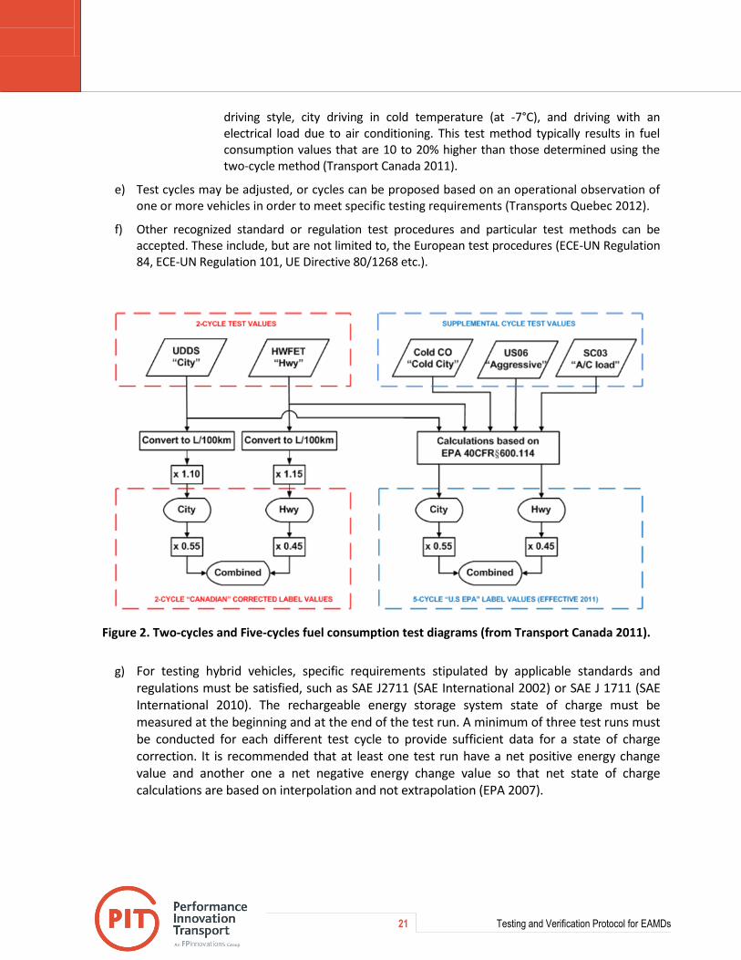
21 Testing and Verification Protocol for EAMDs
driving style, city driving in cold temperature (at -7°C), and driving with an electrical load due to air conditioning. This test method typically results in fuel consumption values that are 10 to 20% higher than those determined using the two-cycle method (Transport Canada 2011).
e) Test cycles may be adjusted, or cycles can be proposed based on an operational observation of one or more vehicles in order to meet specific testing requirements (Transports Quebec 2012).
f) Other recognized standard or regulation test procedures and particular test methods can be accepted. These include, but are not limited to, the European test procedures (ECE-UN Regulation 84, ECE-UN Regulation 101, UE Directive 80/1268 etc.).
Figure 2. Two-cycles and Five-cycles fuel consumption test diagrams (from Transport Canada 2011).
g) For testing hybrid vehicles, specific requirements stipulated by applicable standards and regulations must be satisfied, such as SAE J2711 (SAE International 2002) or SAE J 1711 (SAE International 2010). The rechargeable energy storage system state of charge must be measured at the beginning and at the end of the test run. A minimum of three test runs must be conducted for each different test cycle to provide sufficient data for a state of charge correction. It is recommended that at least one test run have a net positive energy change value and another one a net negative energy change value so that net state of charge calculations are based on interpolation and not extrapolation (EPA 2007).

22 Testing and Verification Protocol for EAMDs
2.3.3.4 Field Testing
a) Field tests recreate real conditions, and give a direct result, which is closer to the real life performance of a product. Therefore, field tests are critical to establish a credible potential return of investment for fleet operators interested in pursuing the implementation of any technology, and especially aerodynamic technologies.
b) Previous standards for track (road) fuel consumption tests, such as the previous version of the SAE J1321 (SAE International 1986), lacked statistical analysis of test data, and constraints on test criteria required to resolve current and anticipated fuel consumption measurement increments. The actual superseding version of the standard (SAE International 2012), stipulates very strict test conditions and data analysis, which ensure the quality and the repeatability of the test results.
c) These standards describe a rigorous fuel consumption test procedure utilizing industry accepted data collection and statistical analysis methods. These test procedures can be conducted on a track or on the road under controlled conditions and supported by extensive data collection and data analysis results. The SAE Type II test procedure uses identical test and control vehicles, for obtaining reference data. This type of testing determines, with a confidence level of 95%, the statistical significance of changes in the fuel consumption of the vehicle on which the tested technology is used. The result is expressed as a nominal value plus and minus the confidence interval. Extensive testing using the 2012 version of SAE J1321 standard showed that the results respond to all the mentioned data quality and analysis criteria, and for technologies providing fuel savings the confidence interval was always less than the nominal value (Surcel 2012b and 2012c).
d) Proposed test procedures for fuel consumption track (road) tests:
i. Light duty vehicles: SAEJ1082 Fuel Economy Measurement Road Test Procedure (SAE International 2008);
ii. Heavy duty vehicles: SAE J1321 Fuel Consumption Test Procedure Type II (SAE International 2012a).
e) Other recognized standard or regulation test procedures and particular test methods can be accepted. Track tests can be conducted at constant speed or using various duty cycles (standardized or based on an operational observation of one or more vehicles in order to meet specific testing requirements). For example specific cycles were developed for testing on test track hybrid vehicles (pick-up and delivery vehicles, and utility vehicles for installing road sign poles), based on specific operational data (Proust and Surcel 2012, Surcel et al 2011).
f) Testing can be tailored to meet the needs of specific locations and vehicle applications. Field fuel consumption tests with specific equipment (such as off-road, utility vehicles, auxiliary power units, refrigeration units, heaters etc.) can be conducted in accordance with specific test procedures, which reflect the operational characteristics. Idling reduction technologies, such as heaters and auxiliary power units, can be tested in a climatic chamber (temperature controlled). The committee responsible for assessing applications may accept a particular method of assessment, depending on the equipment covered by the application. For example, a specific test procedure was developed for fuel consumption testing of refrigeration units in climatic chamber, on specific duty cycle (Surcel 2012a).
g) In order to ensure test repeatability, consistency of results and data quality, test conditions must respect the stipulations of applicable or similar standards and regulations for field testing, such as

23 Testing and Verification Protocol for EAMDs
those of SAE J1321 (SAE International 2012a), concerning weather, weather data collection, variation in weather conditions between tests and between test segments etc.
2.3.4 Test Methods for Indirect Parameters for Evaluating Impact on Fuel Efficiency or GHG Emissions
2.3.4.1 Rolling Resistance Coefficient Testing
a) Tire manufacturers must demonstrate that low rolling resistance tires meet the rolling resistance performance criteria using the ISO 28580 (2009) test method, when compared to similar current conventional tires (which are not designated as a low rolling resistance tires). For both baseline test segment (with conventional tires) and final test segment (with low rolling resistance tires) :
i. A minimum sampling set of three tires is tested;
ii. The tests are conducted with new tires (minimum 800 km and maximum 1600 km of use);
iii. It is recommended that a second set of tests be conducted with worn tires with a tire tread depth of 4 mm (5/32 in);
iv. For both conventional and low rolling resistance tires, the report presents the rolling resistance coefficients, their averages, and the percentage rolling resistance reduction between the two sets of tires. If the test with worn tires is conducted, the report presents rolling resistance coefficients, their averages, and the percentage rolling resistance reduction between the two sets of tires for both conditions (new and worn tires).
b) EPA test procedures can be also used:
i. For low rolling resistance: tire manufacturers must demonstrate that a tire model has a rolling resistance coefficient at or below the target, using the SAE J1269 tire rolling resistance test method under the conditions set forth in Table 3 of SAE J1269 (SAE International 2006), or the ISO 28580 rolling resistance test method and the performance criteria set forth in Appendix E, Figure 2 (EPA 2011a);
ii. For the determination of low rolling resistance performance or tire retread technologies, the: performance criteria set forth in Appendix E, Figure 3 (EPA 2011b).
c) The usage of ISO 28580 is preferred. According to ETRTO (2009):
i. A study indicated that rolling resistance results may vary up to 20% when measuring identical tires on different machines;
ii. ISO 28580:2009 includes a method for correlating measurement results to allow inter-laboratory comparisons;
iii. The alignment will be done between a “Reference Laboratory” and a “Candidate Laboratory” using pre-determined alignment tyres;
iv. The alignment process vs. a Reference Laboratory may shift data of the individual Candidate Labs up or down. This shift depends on the absolute RR level as measured in the Reference Laboratory;
v. The choice of the Reference Laboratory is very important.
24 Testing and Verification Protocol for EAMDs
2.3.4.2. Wind Averaged Coefficient of Drag Testing
a) CFD simulations and wind tunnel testing should be a normal stage of the development of an aerodynamic drag reduction product.
b) Wind tunnel tests are conducted in very controlled conditions and the direct result of such tests is a reduction of the drag coefficient: the probable fuel consumption reduction is only estimated based on this drag reduction. However, wind tunnel testing could be considered for comparative testing, such as obtaining approval extensions for minor modifications to technologies that have been already approved on the basis of track testing, similar to California Air Resources Board (CARB) requirements (CARB 2012). These modifications must not affect the position, the size, and the installation angles of the device. The wind tunnel tests must be conducted on full-scale vehicle, or on a high fidelity detailed 1/8 scale or larger model.
c) The CARB wind tunnel test protocol defines the wind tunnel-based method for obtaining approval for modifications to SmartWay trailer technologies that have not been pre-approved. The test procedure is in accordance with SAE J1252 (SAE International 2012b), with some exceptions and provisions:
i. The minimum acceptable test Reynolds number shall be 1 million;
ii. The aerodynamic tests will include yaw angles of 0, 9, 6, 3, 1, 0, -1,-3, -6, -9, and 0 degrees;
iii. The coefficient of drag results from the first and last 0 degree yaw angle runs are used to check for repeatability; the remaining 9 collection points are used to calculate the wind average coefficient of drag (Cdw) for vehicle operational speeds of 50 mph, 55 mph, 60 mph, 65 mph, 70 mph, and 75 mph;
iv. The independent wind tunnel test facility shall run three repeats of the baseline tractor-trailer test, taking into account the measurement sensitivity of the wind tunnel.
d) CFD simulations can be used if they meet the requirements of existing applicable standards or regulations. For example a SAE standard is presently under development (SAE J2966, “Guidelines for Aerodynamic Assessment of Medium and Heavy Commercial Ground Vehicles Using Computational Fluid Dynamics”).
2.3.3.3. Mass Reduction Testing
The proposed procedure is similar to the process used by the Ministère des Transports du Québec (Transport Quebec 2012) outlined below.
a) Specify the type of equipment that represents the basis for comparison (baseline scenario): three similar and current models must be selected in order to establish a representative basis for comparison. Specifications must be provided for the models selected. The average mass of these models is the mass against which the equipment is compared.
b) Determine the masses of the replacement equipment and of the original equipment by weighing. The mass of the equipment to be assessed must be compared against the average mass of the baseline selected equipment.
c) Mass reduction technology must not negatively affect other constructive parameters of the vehicle, such as aerodynamic performance, rolling resistance, or safety. If the Verification Organization considers that any of these parameters could be affected, the necessary additional testing must be conducted, such as fuel consumption track test, or structural tests.

25 Testing and Verification Protocol for EAMDs
2.4. Test Report
The report must adhere to the requirements of the ETV General Test Protocol (Environment Canada 1998) and the specific requirements of the applicable standard and regulation (SAE International 2012, Transports Quebec 2012). The report must be issued in accordance with the legal requirements of the province where it is drawn up (prepared, verified and signed by a professional registered engineer).
The report must include at minimum elements listed below,
a) Introduction
i. Background of the testing process
ii. Testing facility name, location and testing date and time, testing personnel and report author
b) Technology description
i. Scope, applicability, functioning mode, installation, operational requirements, constraints
ii. Declared impact on emissions and fuel efficiency, as well as on safety
iii. Sufficient pictures, drawing or schematics of the technology installed on the test object (vehicle, engine, equipment etc.)
c) Objectives
i. Technology performance claims evaluated
ii. The potential to reduce emissions or improve fuel efficiency must be among the objectives.
d) Testing Methodology
i. Type of data collected (emissions, fuel consumption);
ii. Method for the evaluation of emissions or fuel consumption, including the description of relevant standards or regulations
iii. Test duty cycle description
iv. If applicable: test track (site) description, drawings or photos, and details
v. If applicable: test track (site) weather data collection sites (location)
vi. Detailed characteristics of the vehicles or equipment used for testing
e) Data analysis
i. According to GTP and applicable standard or regulation
ii. The focus of testing is to determine, with a confidence level of 95%, the statistical significance of changes in the emissions of the vehicle or engine, on which the tested technology is used. The nominal values for the changes in emissions are determined from the analysis of the measured emission data and reflect the changes resulting from the modification being tested on the test vehicle or engine.
26 Testing and Verification Protocol for EAMDs
f) Results
i. These are the results of the evaluation, fuel savings or emission reduction attributable to the equipment compared to the chosen reference scenario.
ii. Results must be expressed as a nominal value plus and minus the confidence interval.
iii. The nominal values for the changes in the fuel consumption and/or emissions are determined from the analysis of the measured fuel or emission data and reflect the changes resulting from the modification being tested on the test vehicle or engine.
iv. The confidence interval must be less than the nominal result for having a statistically valid result.
g) Discussion
i. Explanation of the results obtained in comparison with the anticipated results
ii. Identification and explanation of the parameters that could have influenced the results
iii. Presentation of the limitations of the test procedure and the applicability of the results. For example, if indirect methods are used and fuel savings are calculated based on the results of such methods, mention that fuel savings are the results of calculation and not of direct measurements.
iv. Quantification of the environmental impact
h) Conclusions and recommendations
i. Summary of test results
ii. Description of how test results support performance claim(s)
iii. Relation of results to relevant regulatory requirements where appropriate
iv. Recommendations regarding the tested technology
i) References
i. All relevant technical literature and appropriate materials referenced during the testing design and/or planning phase.
j) Raw Data
i. Vehicle, engine or equipment data form
ii. Test forms describing test conditions, measured parameters, and data analysis
iii. Time history plot of all environmental or weather conditions during testing

27 Testing and Verification Protocol for EAMDs
3. Verification
The verification process is a third party expert evaluation of the technology and of the independent third party testing based on the General Verification Protocol (GVP).
The GVP outlines the principles of verification. If supplemental documents are necessary, the applicant, the Canadian ETV Program and the Verification Organization (VO) will discuss the appropriate requirements, if required. Figure 3 presents the verification process (Environment Canada 2012).
Several types of applicants are eligible to apply to the ETV program for verification:
Environmental technology vendors who have new technology;
Vendors who provide equipment-based environmental services that can make claims based solely on measurable performance of the equipment or technology used;
Technology developers that have early stage technology.
Figure 3. ETV Canada verification process (from Environment Canada 2012).
Following the GVP, a VO evaluates the integrity of supplied data, and the validity of the associated performance claims based on this data. The following requirements must be met for a claim to be verified:
The technology must provide a net environmental benefit;
The technology is based on sound scientific and engineering principles;
The claim is fully supported by independently generated, peer-review quality data, which are supplied by the applicant or generated upon the applicant's request through a test program conducted by a qualified testing agency;
The conditions of performance for the claim are clearly defined.

THIS PAGE INTENTIONALLY LEFT BLANK
29 Testing and Verification Protocol for EAMDs
Discussion and Recommendations
Cost analysis is not a component of the verification, but could provide additional information to the user of the technology under consideration, and it is likely to be demanded by fleet managers as a requirement for purchasing the technology. The cost analysis should:
o Indicate the additional cost attributable to the equipment;
o Present the hypothesis used for analysis: distance travelled, number of vehicles, baseline fuel consumption or emissions, cost of fuel, etc.;
o Using the results obtained and the additional cost of the equipment, estimate the return on investment in months or years.
In the verification process, test reports and certifications obtained in other countries should be considered and could be accepted, depending on the results of the screening and of the verification. Moreover, there is an ISO initiative for standardizing ETV process, such that an ETV verification issued in one country could be accepted in other countries.
Life cycle analysis (LCA) is not the objective of this protocol: verification can only be applied against measurable performance criteria. LCA is an important decision-making tool, but environmental performance verification of technologies based on a full-range of comprehensive systemic parameters would be extremely difficult to implement.
It should be mentioned that the while the process must be accurate, it should also be cost effective to facilitate access to verification for technology suppliers.
Conclusions
This testing and verification protocol helps guide the demonstration and deployment of effective engine and vehicle technologies and solutions. The protocol meets the requirements of the Canadian ETV Program and the program’s General Verification Protocol. The protocol has been developed in consultation with a Technical Advisory Committee, which provided input and technical expertise.
The protocol presents the screening, testing and verification process. It also presents the general test methodology and existing test methods that can be used, with reference to applicable standards and regulations, in a manner that is consistent with the framework of the Canadian ETV Program General Test Protocol.
Considering that specific regulations and standards are already in place across a number of jurisdictions, the protocol does not detail test procedures. However, because unique technologies may require specific test plans that cannot be found in existing standards, it is acknowledged that particular testing methods may be accepted, depending on the equipment covered by the application.
30 Testing and Verification Protocol for EAMDs
Acknowledgements
The authors would like to thank the members of the Technical Advisory Committee for their participation and the very valuable input and feedback provided in the process of developing the testing and verification protocol.
The support of Globe Performance Solutions and Environment Canada is gratefully acknowledged.
31 Testing and Verification Protocol for EAMDs
References
Canadian ETV. 2012. Canadian Environmental Technology Verification Program. Applicant Information Package. Toronto, ON, Canada.
CARB (California Air Ressources Board). 2012. Implementation Guidance for the Tractor-Trailer GHG Regulation. Emission Research and Regulatory Development Branch.
CFR (Code of Federal Regulation). 2008. Title 40 Part 1065 Engine Testing Procedures. Part 1065 – Subpart J PEMS testing, §1065.901.
Environment Canada. 1998. Environmental Technology Verification General ETV Test Protocol. Draft Test Protocol - Version 2.0. January 1998. Gatineau, QC, Canada.
Environment Canada. 2012a. Environmental Technology Verification General Verification Protocol (GVP). Review of Application and Assessment of Technology. June 2012. Gatineau, QC, Canada.
Environment Canada. 2012b. National Inventory Report, 1990-2010: Greenhouse Gas Sources and Sinks in Canada, Part 2, Annex 8, Table A8–11 Emission Factors for Energy Mobile Combustion Sources, p 199. ISSN: 1910-7064. Gatineau, QC, Canada.
EPA (United States Environmental Protection Agency). 2007. SmartWay Fuel Efficiency Test Protocol for Medium and Heavy Duty Vehicles. Working Draft. EPA-420-P-003. Washington, DC.
EPA (United States Environmental Protection Agency). 2011a. SmartWay Verified Low Rolling Resistance Tires Performance Requirements. Tire Verfification Process. EPA-420-F-12-024. Washington, DC, USA.
EPA (United States Environmental Protection Agency). 2011b. EPA Verified Low Rolling Resistance Tires Interim Performance Requirements for Retread Products. Washington, DC, USA.
Environmental Protection Agency (EPA) and National Highway Traffic Safety Administration (NHTSA) DOT. 2011. Greenhouse Gas Emissions Standards and Fuel Efficiency Standards for Medium- and Heavy-Duty Engines and Vehicles. Federal Register / Vol. 76, No. 179 / Thursday, September 15, 2011 / Rules and Regulations.
ETRTO (European Tyre and Rim Technical Organization). 2009. UPDATE ISO 28580. Working Paper No. STD-01-05 1st STD meeting, 23 July 2009, agenda item 4.
ETV Canada - OCETA. 2007. Draft Protocol for Testing and Verifying the Performance of Engine and Vehicle After-market Technologies. Prepared by ETV Canada – a division of OCETA. Mississauga, ON, Canada.
IPCC. 2007. Climate Change 2007 Synthesis Report. Contribution of Working Groups I, II and III to the Fourth Assessment Report of the Intergovernmental Panel on Climate Change Core Writing Team, Pachauri, R.K. and Reisinger, A. (Eds.) IPCC, Geneva, Switzerland. pp 104
ISO (International Standard Organization). 2009. ISO 28580: Passenger car, truck and bus tyres. Methods of measuring rolling resistance. Single point test and correlation of measurement results.
Jones, F., E. 1978. The Air Density Equation and the Transfer of the Mass Unit, Journal of Research of the National Bureau of Standards, 83, 419-428, Gaithersburg, MD.
Kenworth Truck Company. 2008. White Paper on Fuel Economy.
OCETA. 2010. Vehicle and Engine After Market Technology : Feasibility Study of a Screening, Testing, and Verification Demonstration Program. Mississauga, ON, Canada.

32 Testing and Verification Protocol for EAMDs
Proust, A.; Surcel, M.D. 2012. Evaluation of Class 7 Diesel-Electric Hybrid Trucks, Paper no. 2012-01-1987, SAE 2012 Commercial Vehicle Engineering Congress & Exhibition, Rosemont – Chicago, IL, October 2 – 3 , 2012.
SAE International. 1986. SAE J1321. SAE Fuel Consumption Test Procedure – Type II, SAE Surface Vehicle Recommended Practice. Warrendale, PA.
SAE International. 2002. SAE J 2711, Recommended Practice for Measuring Fuel Economy and Emissions of Hybrid-Electric and conventional Heavy-Duty Vehicles, SAE Surface Vehicle Recommended Practice. Warrendale, PA.
SAE International. 2006. SAE J 1269. Rolling Resistance Measurement Procedure for Passenger Car, Light Truck, and Highway Truck and Bus Tires. Warrendale, PA.
SAE International. 2008. SAE J 1082. Fuel Economy Measurement Road Test Procedure, SAE Surface Vehicle Recommended Practice. Warrendale, PA.
SAE International. 2010. SAE J1711. Recommended Practice for Measuring the Exhaust Emissions and Fuel Economy of Hybrid-Electric Vehicles, Including Plug-in Hybrid Vehicles, SAE Surface Vehicle Recommended Practice. Warrendale, PA.
SAE International. 2011. SAE J 1094. Constant Volume Sampler System for Exhaust Emissions Measurement, SAE Surface Vehicle Recommended Practice. Warrendale, PA.
SAE International. 2012a. SAE J1321. SAE Fuel Consumption Test Procedure – Type II, SAE Surface Vehicle Recommended Practice. Warrendale, PA.
SAE International. 2012b. SAE J1252. SAE Wind Tunnel Test Procedure for Trucks and Buses, SAE Surface Vehicle Recommended Practice. Warrendale, PA.
Surcel, M.D.; Michaelsen, J.; Provencher, Y. 2008. Track-test evaluation of aerodynamic drag reducing measures for class 8 tractor-trailers, Paper no. 2008-01-2600, SAE 2008 Commercial Vehicle Engineering Congress & Exhibition, Rosemont – Chicago, IL, October 7 – 9, 2008.
Surcel, M.D.; Michaelsen, J. 2009. Fuel consumption tests for evaluating the accuracy and precision of truck engine electronic control modules to capture fuel data, Paper no. 2009-01-1605, SAE 2009 Commercial Vehicle Engineering Congress & Exhibition, Rosemont – Chicago, IL, October 6 – 8, 2009.
Surcel, M.D.; Michaelsen, J.; Provencher, Y. 2011. Development of a Fuel Consumption Test Procedure for Representative Urban Duty Cycles, Paper no. 2011-01-2291, SAE 2011 Commercial Vehicle Engineering Congress & Exhibition, Rosemont – Chicago, IL, September 13 – 14, 2011.
Surcel, M.D. 2012a. Development of a Fuel Consumption Test Procedure for Refrigeration Units. SAE International Journal of Commercial Vehicle 5(2):2012, doi:10.4271/2012-01-2060.
Surcel, M.-D. 2012b. Energotest 2012 Spring Edition: Test Campaign Summary Report. FPInnovations, Pointe-Claire, QC. 18 p.
Surcel, M.-D. 2012c. Energotest 2012 Fall Edition: Test Campaign Summary Report. FPInnovations, Pointe-Claire, QC. 34 p.
Transport Canada. 2011. Subaru Forester PZEV Advanced Gasoline Partial Zero Emission Vehicle Test Results Report. July 2011. Ottawa, ON.
Transports Québec. 2012. Assistance Application Guide for Research and Pilot Projects. Direction du transport routier des marchandises, Ministère des Transports du Québec. Québec, QC, Canada.

33 Testing and Verification Protocol for EAMDs
Appendix A. Technical Advisory Committee
Table 4. Technical advisory committee
No. Name Company / Organization Position Category
TAC MEMBERS
1 A. Siddiq Khan, Ph.D. ACEEE Senior Researcher, Transportation Lead
Research
2 Brian Rennie Bridgestone Firestone Director, Engineering Industry : OEM
3 Geoffrey Wood Canadian Trucking Alliance Vice-president, Operations & Safety
Industry : Transport
4 Alain Vallée, Eng. City of Levis Manager, Environment Division Municipality
5 Jean-Marc Lavigne City of Montreal Division Manager Municipal Fleet Municipality
6 Robert Russell City of St-John Manager, Fleet Administration Municipality
7 Drew Shintani City of Toronto Business Analyst Fleet Services Division
Municipality
8 Sam Waltzer EPA, Office of Transportation Air Quality
Manager, SmartWay Technology Government
9 Jim Fearn ERMD, Environment Canada Engineer Research and testing: Government
10 Jan Michaelsen, F.E. FPInnovations Research Leader, Transport & Energy
Research and testing
11 John Neate GLOBE Performance Solutions
CEO Technology Verification organization
12 Philippe Bellon, B. Eng., MBA Metrolinx Transit Procurement Initiative
Manager Government
13 François Beauchamp Michelin North America (Canada) Inc.
Special Project Coordinator Industry: OEM
14 Frédéric Côté, Eng. MTQ Engineer, Technical Standardization Department, Trucking Division
Government
15 Cristian Tabra, P.Eng. NRC Manager, Commercial Vehicles NRC-Surface Transportation
Research and testing: Government
16 Jeff Patten, P. Eng. NRC Manager, Test & Evaluation Engineering Road Vehicle and Military System Division
Research and testing: Government
17 Jim Wassermann PAMI Vice-president Research and testing
18 Claude Sauvageau PMG Technologies Vice-president, Testing Research and testing
19 Marc Belzile Transport Canada Vehicle Programs Division Government

34 Testing and Verification Protocol for EAMDs
Table 4. Technical advisory committee (continuations)
No. Name Company / Organization Position Category
TAC MEMBERS
20 Yves Maurais, Eng. Transport Robert Technical Director Industry : Transport
21 Ken Webster, Transportation Research Center Inc.
Manager Operations Research and testing
22 Philippe Desjardins Transtex Composite Engineer Industry : OEM
23 Zhongchao Tan, Dr. University of Waterloo Associate Professor Academia
24 M. Zengh, Dr. University of Windsor Professor, Clean Diesel Engine Technologies CR Chair
Academia
25 Kevin Oversby Westport Innovations Inc. Emissions Certification Engineer Industry : OEM
OBSERVERS
26 Benoit Desforges, Eng., M.Sc.
Environment Canada Section Head, Technology Programs Science and Technology Branch
Government
27 Jeffrey Guthrie Environment Canada Science and Technology Programs Environment Canada
Government
28 Kelly Vandeligt Environment Canada Senior Project Officer Technology Programs Science & Technology Branch
Government
ORGANIZING TEAM
29 Bernard Ouellet FPInnovations-PIT PIT Leader of Operations Research and testing
30 Adime Bonsi FPInnovations-PIT Researcher PIT Research and testing
31 Falama Souley FPInnovations-PIT Researcher PIT Research and testing
32 Marius Surcel FPInnovations-PIT PIT Technical Leader Research and testing
35 Testing and Verification Protocol for EAMDs
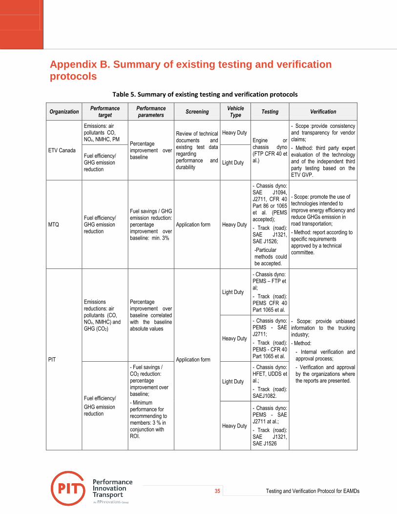
Appendix B. Summary of existing testing and verification protocols
Table 5. Summary of existing testing and verification protocols
Organization Performance
target Performance parameters
Screening Vehicle
Type Testing Verification
ETV Canada
Emissions: air pollutants CO, NOx, NMHC, PM
Percentage improvement over baseline
Review of technical documents and existing test data regarding performance and durability
Heavy Duty
Engine or chassis dyno (FTP CFR 40 et al.)
- Scope :provide consistency and transparency for vendor claims;
- Method: third party expert evaluation of the technology and of the independent third party testing based on the ETV GVP.
Fuel efficiency/ GHG emission reduction
Light Duty
MTQ Fuel efficiency/ GHG emission reduction
Fuel savings / GHG emission reduction: percentage improvement over baseline: min. 3%
Application form Heavy Duty
- Chassis dyno: SAE J1094, J2711, CFR 40 Part 86 or 1065 et al. (PEMS accepted);
- Track (road): SAE J1321, SAE J1526;
-Particular methods could be accepted.
- Scope: promote the use of technologies intended to improve energy efficiency and reduce GHGs emission in road transportation;
- Method: report according to specific requirements approved by a technical committee.
PIT
Emissions reductions: air pollutants (CO, NOx, NMHC) and GHG (CO2)
Percentage improvement over baseline correlated with the baseline absolute values
Application form
Light Duty
- Chassis dyno: PEMS – FTP et al;
- Track (road): PEMS CFR 40 Part 1065 et al.
- Scope: provide unbiased information to the trucking industry;
- Method:
- Internal verification and approval process;
- Verification and approval by the organizations where the reports are presented.
Heavy Duty
- Chassis dyno: PEMS - SAE J2711;
- Track (road): PEMS - CFR 40 Part 1065 et al.
Fuel efficiency/
GHG emission reduction
- Fuel savings / CO2 reduction: percentage improvement over baseline;
- Minimum performance for recommending to members: 3 % in conjunction with ROI.
Light Duty
- Chassis dyno: HFET, UDDS et al.;
- Track (road): SAEJ1082.
Heavy Duty
- Chassis dyno: PEMS - SAE J2711 at al.;
- Track (road): SAE J1321, SAE J1526
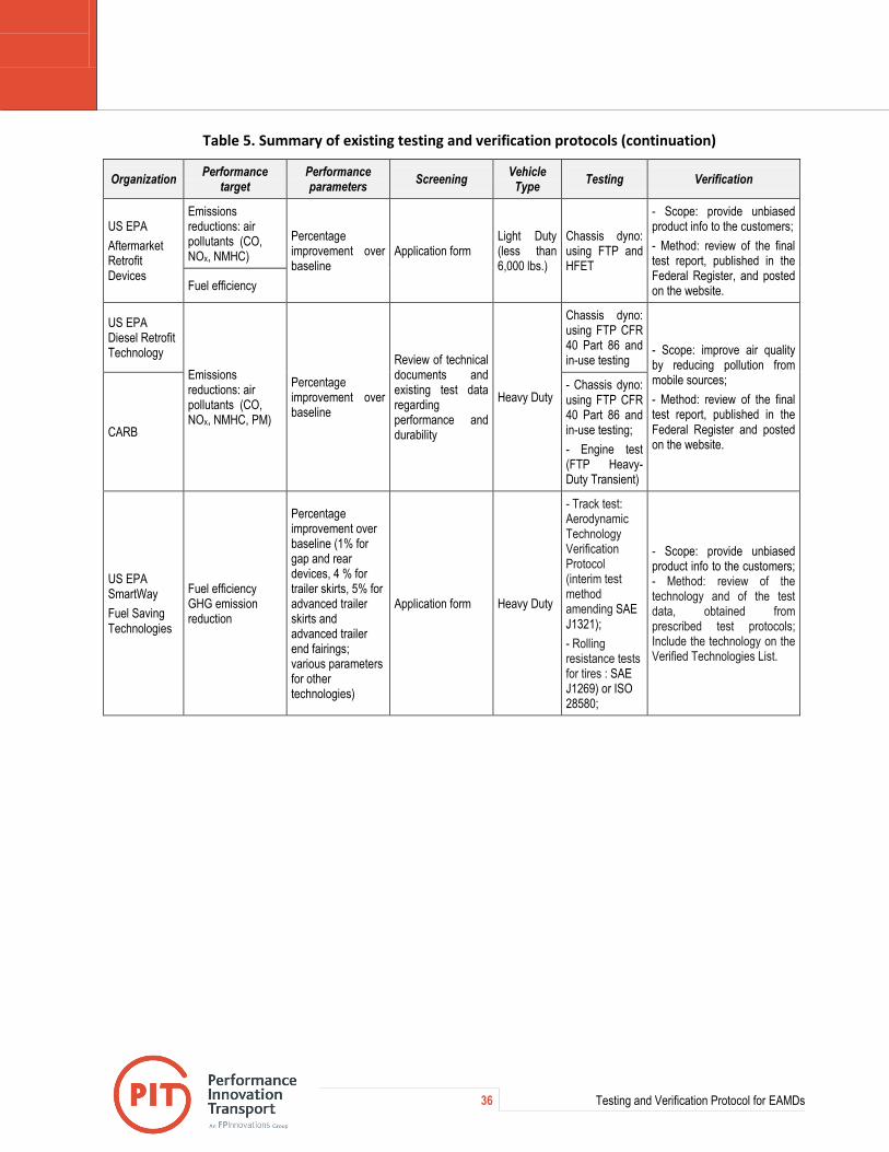
36 Testing and Verification Protocol for EAMDs
Table 5. Summary of existing testing and verification protocols (continuation)
Organization Performance
target Performance parameters
Screening Vehicle
Type Testing Verification
US EPA
Aftermarket Retrofit Devices
Emissions reductions: air pollutants (CO, NOx, NMHC)
Percentage improvement over baseline
Application form Light Duty (less than 6,000 lbs.)
Chassis dyno: using FTP and HFET
- Scope: provide unbiased product info to the customers;
- Method: review of the final test report, published in the Federal Register, and posted on the website. Fuel efficiency
US EPA Diesel Retrofit Technology
Emissions reductions: air pollutants (CO, NOx, NMHC, PM)
Percentage improvement over baseline
Review of technical documents and existing test data regarding performance and durability
Heavy Duty
Chassis dyno: using FTP CFR 40 Part 86 and in-use testing
- Scope: improve air quality by reducing pollution from mobile sources;
- Method: review of the final test report, published in the Federal Register and posted on the website.
CARB
- Chassis dyno: using FTP CFR 40 Part 86 and in-use testing;
- Engine test (FTP Heavy-Duty Transient)
US EPA SmartWay
Fuel Saving Technologies
Fuel efficiency GHG emission reduction
Percentage improvement over baseline (1% for gap and rear devices, 4 % for trailer skirts, 5% for advanced trailer skirts and advanced trailer end fairings; various parameters for other technologies)
Application form Heavy Duty
- Track test: Aerodynamic Technology Verification Protocol (interim test method amending SAE J1321);
- Rolling resistance tests for tires : SAE J1269) or ISO 28580;
- Scope: provide unbiased product info to the customers; - Method: review of the technology and of the test data, obtained from prescribed test protocols; Include the technology on the Verified Technologies List.

37 Testing and Verification Protocol for EAMDs
Appendix C. Self-assessment Application Form

38 Testing and Verification Protocol for EAMDs

39 Testing and Verification Protocol for EAMDs

THIS PAGE INTENTIONALLY LEFT BLANK

41 Testing and Verification Protocol for EAMDs
Appendix D. Performance Criteria for Tires
Figure 4. Performance criteria for low rolling resistance tires (from EPA 2011a).
Figure 5. Performance criteria for retread tires (adapted from EPA 2011b).

THIS PAGE INTENTIONALLY LEFT BLANK

43 Testing and Verification Protocol for EAMDs
Appendix E. Test Conditions for PEMS Emissions Field Testing
Table 6. Test conditions for PEMS emissions field testing
Test condition Requirement
Mean wind speed during a test run ≤ 19.3 km/h (12 mph)
Maximum wind speed (gusts) ≤ 24.1 km/h (15 mph)
Mean wind speed change between segments and runs ≤ 8 km/h (5 mph)
Temperature range 4°C (40°F) - 38°C (100 F°)
Mean temperature change between segments and between runs ≤ 17°C (30 F°)
Precipitations and fog None
Weather measurement sampling Max. 60 s
Air density variation between segments and between runs 0.1 kg/m3
Note: Air density can be computed from measurements of ambient temperature, humidity, and barometric pressure (Jones 1978).

THIS PAGE INTENTIONALLY LEFT BLANK

THIS PAGE INTENTIONALLY LEFT BLANK

For more information:
Marius-Dorin Surcel, Eng., M.A.Sc.
Technical Leader
570, boul. Saint-Jean, Pointe-Claire (QC) H9R 3J9
514 782-4519
[email protected] www.pit.fpinnovations.ca www.fpinnovations.ca