testequipmentshop.com air2guide differential pressure switch tes a2g 40 data sheet
TRANSCRIPT

8/2/2019 Testequipmentshop.com Air2Guide Differential Pressure Switch TES A2G 40 Data Sheet
http://slidepdf.com/reader/full/testequipmentshopcom-air2guide-differential-pressure-switch-tes-a2g-40-data 1/2
ElectronicPressure Measurement
R
Description
Version
In accordance with the European low-voltage directive73/23/EEC
Reference table below for Dead Band,
Switiching Increments and Measuring Ranges
Maximum pressure
200 InWC
Page 1 of 2WIKA Datasheet A2G-40 ·04/2011
Dierential Pressure SwitchesType A2G-40, air2guide S
Dierential Pressure Switch air2guide S, Type A2G-40
Applications
Ideal for use with air and other non-combustible gases
Monitoring of air lters, fans, industrial cold air circuits,
air ow in ventilation ducts and the control of air and re
shutters
Overpressure monitoring in cleanrooms and laboratories
Special Features
Compact size Easy installation and mounting
Robust housing and functional design
Standard accessories included
Very reliable, > 1 mio. switching cycles
Operating temperatureAmbient: -40 °F… +185 °F
Medium: -20 °F... +160 °F
Ingress protection
NEMA 3 (IP 54 per EN 60 529 / lEC 529)
Weight
5.2 ounces
WIKA Datasheet A2G-40
Set Point RangeInWC (Pa)
SwitchingIncrementsInWC (Pa)
Approx. Dead Bandat min. Set Point
InWC (Pa)
Approx. Dead Bandat mmax. Set Point
InWC (Pa)
0.08 to 0.80 (20…200) 0.04 (10) + 0.02 (5) + 0.08 (20)
0.12 to 1.20 (30…300) 0.08 (20) + 0.02 (5) + 0.12 (30)
0.12 to 2.00 (30…500) 0.08 (20) + 0.02 (5) + 0.12 (30)
0.16 to 2.40 (40…600) 0.12 (30) + 0.02 (5) + 0.12 (30)
0.40 to 6.00 (100…1500) 0.30 (80) + 0.04 (10) + 0.20 (50)
2.00 to 18.0 (500…4500) 0.70 (180) + 0.20 (50) + 0.80 (200)
8/2/2019 Testequipmentshop.com Air2Guide Differential Pressure Switch TES A2G 40 Data Sheet
http://slidepdf.com/reader/full/testequipmentshopcom-air2guide-differential-pressure-switch-tes-a2g-40-data 2/2
WIKA Instrument Corporation
1000 Wiegand Boulevard
Lawrenceville, GA 30043
Tel (770) 513-8200 Toll-free 1-888-WIKA-USA
Fax (770) 338-5118
E-Mail [email protected]
R
WIKA Datasheet A2G-40 · 04/2011Page 2 of 2
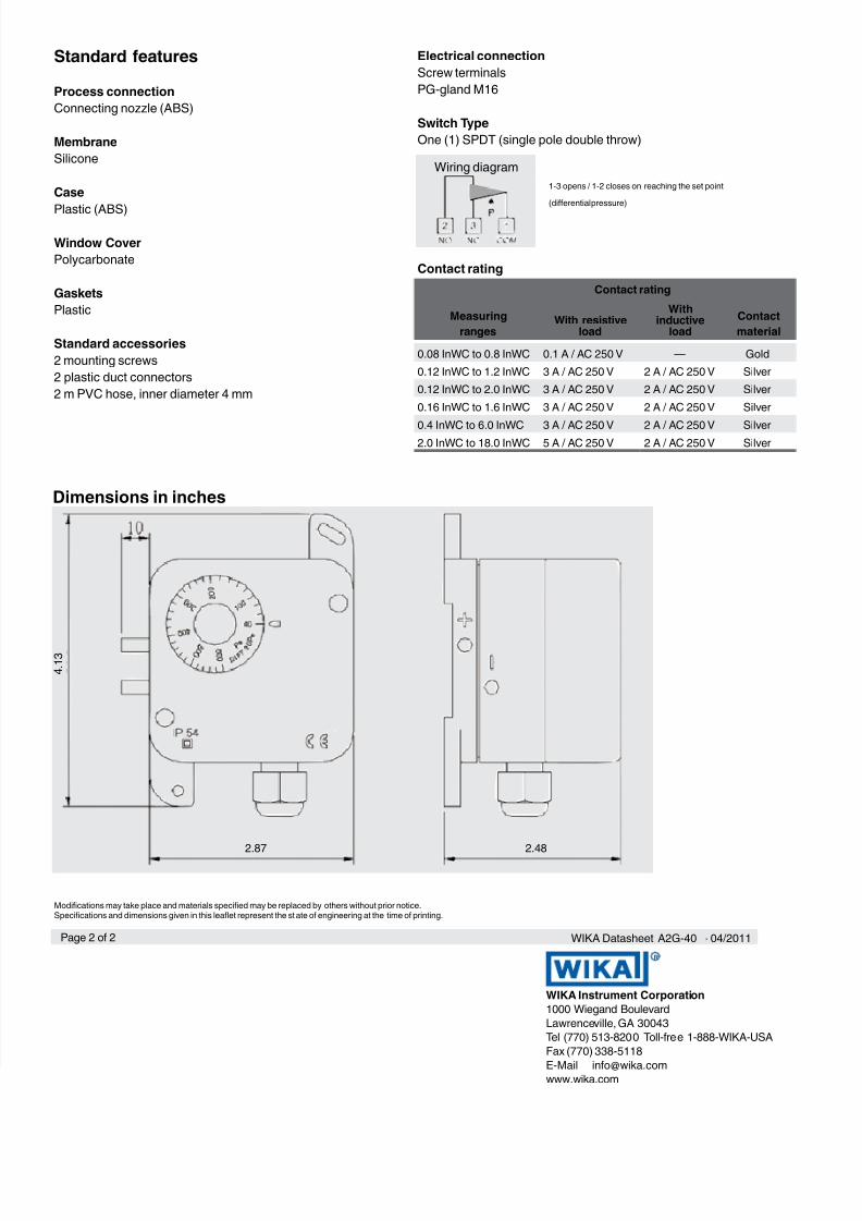
Electrical connection
Screw terminals
PG-gland M16
Switch Type
One (1) SPDT (single pole double throw)
1-3 opens / 1-2 closes on reaching the set point
(dierential pressure)
Contact rating
Standard features
Process connection
Connecting nozzle (ABS)
Membrane
Silicone
Case
Plastic (ABS)
Window Cover
Polycarbonate
Gaskets
Plastic
Standard accessories
2 mounting screws
2 plastic duct connectors
2 m PVC hose, inner diameter 4 mm
Measuring
ranges
Contact rating
Contact
materialWith resistive
load
Withinductive
load
0.08 InWC to 0.8 InWC 0.1 A / AC 250 V — Gold
0.12 InWC to 1.2 InWC 3 A / AC 250 V 2 A / AC 250 V Silver
0.12 InWC to 2.0 InWC 3 A / AC 250 V 2 A / AC 250 V Silver
0.16 InWC to 1.6 InWC 3 A / AC 250 V 2 A / AC 250 V Silver
0.4 InWC to 6.0 InWC 3 A / AC 250 V 2 A / AC 250 V Silver2.0 InWC to 18.0 InWC 5 A / AC 250 V 2 A / AC 250 V Silver
Wiring diagram
Dimensions in inches
Modications may take place and materials specied may be replaced by others without prior notice.Specications and dimensions given in this leaet represent the st ate of engineering at the time of printing.
4 .
1 3
2.87 2.48