test response compaction using multiplexed parity trees
TRANSCRIPT
lEEE TRANSACTIONS ON COMPUTER-AIDED DESIGN OF INTEGRATED CIRCUITS AND SYSTEMS, VOL. 15, NO. 1 I , NOVEMBER 1996 1399
Test Response Compaction Using Multiplexed Parity Trees
Krishnendu Ghakrabarty, Member, IEEE, and John P. Hayes, Fellow, IEEE
Abstruct- Built-in self-testing requires test response streams from many observation points to be merged (space compaction) and compressed (time compaction) into a short signature. The compaction circuits should be transparent to error propaga- tion in order to minimize aliasing, which occurs when a faulty response maps to the fault-free signature. We investigate the use of multiplexed parity trees (MPT’s) for zero-aliasing space compaction. MPT’s combine the error propagation properties of multiplexers and parity trees, and ensure zero aliasing via multistep compaction. We present two design techniques based on MPTs-output selection and fanout insertion-that eliminate aliasing for both deterministic and pseudorandom test sets. Our experiments with the ISCAS benchmark circuits show that zero aliasing can be achieved with small test sets and moderate hard- ware overhead. We also demonstrate that a very high percentage of single stuck-line faults in the compaction circuit are detected by the test patterns applied to the circuit under test.
I. INTRODUCTION
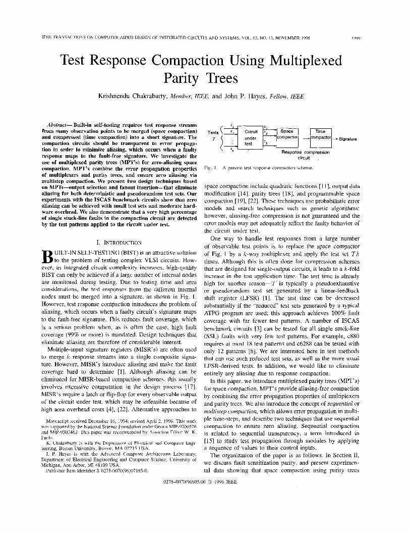
UILT-IN SELF-TESTING (BIST) is an attractive solution B to the problem of testing complex VLSI circuits. How- ever, as integrated circuit complexity increases, high-quality BIST can only be achieved if a large number of internal nodes are monitored during testing. Due to testing time and area considerations, the test responses from the different internal nodes must be merged into a signature, as shown in Fig. 1. However, test response compaction introduces the problem of aliasing, which occurs when a faulty circuit’s signature maps to the fault-free signature. This reduces fault coverage, which is a serious problem when, as is often the case, high fault coverage (99% or more) is mandated. Design techniques that eliminate aliasing are therefore of considerable interest.
Multiple-input signature registers (MISR’s) are often used to merge IC response streams into a single composite signa- ture. However, MISR’s introduce aliasing and make the fault coverage hard to determine [l]. Although aliasing can be eliminated for MISR-based compaction schemes, this usually involves excessive computation in the design process [17]. MISR’s require a latch or flip-flop for every observable output of the circuit under test, which may be infeasible because of high area overhead costs [4], [22]. Alternative approaches to
Manuscript received Dccember 16, 1994; revised April 2, 1996. This work was supported by the National Science Foundation under Grants MIP-9200526 and MIP-9503463. This paper was recommended by Associate Editor W. K. Fuchs.
K. Chakrabarty is with the Department of Electrical and Computer Engi- neering, Boston University, Boston, MA 02215 USA.
J . P. Hayes is with the Advanced Computer Architecture Laboratory, Department of Electrical Engineering and Computer Science, University of Michigan, Ann Arbor, MI 48109 USA.
Publisher Item Identifier S 0278-0070(96)07185-0.
X
Tests 13 Circuit DFH-1 T under compactor compactor signature
test ‘ k
Response compression xtl
circuit
Fig. 1 . A gencric test response compaction scheme.
space compaction include quadratic functions [ 111, output data modification [14], parity trees [18], and programmable space compaction [ 191, [22]. These techniques use probabilistic error models and search techniques such as genetic algorithms; however, aliasing-free compression is not guaranteed and the error models may not adequately reflect the faulty behavior of the circuit under test.
One way to handle test responses from a large number of observable test points is to replace the space compactor of Fig. 1 by a k-way multiplexer and apply the test set 7 k times. Although this is often done for compression schemes that are designed for single-output circuits, it leads to a k-fold increase in the test application time. The test time is already high for another reason-7 is typically a pseudoexhaustive or pseudorandom test set generated by a linear-feedback shift register (LFSR) [l]. The test time can be decreased substantially if the “reduced’ test sets generated by a typical ATPG program are used; this approach achieves 100% fault coverage with far fewer test patterns. A number of ISCAS benchmark circuits [ 3 ] can be tested for all single stuck-line (SSL) faults with very few test patterns. For example, c880 requires at most 18 test patterns and c6288 can be tested with only 12 patterns [SI. We are interested here in test methods that can use such reduced test sets, as well as the more usual LFSR-derived tests. In addition, we would like to eliminate entirely any aliasing due to response compaction.
In this paper, we introduce multiplexed parity trees (MPT’s) for space compaction. MPT’s provide aliasing-free compaction by combining the error propagation properties of multiplexers and parity trees. We also introduce the concept of sequenlial or multistep compaction, which allows error propagation in multi- ple time-steps, and describe two techniques that use sequential compaction to ensure zero aliasing. Sequential compaction is related to sequential transparency, a term introduced in [ 151 to study test propagation through modules by applying a sequence of values to their control inputs.
The organization of the paper is as follows. In Section 11, we discuss fault sensitization parity, and present experimen- tal data showing that space compaction using parity trees
0278-0070/96$05.00 0 1996 IEEE

1400 IEEh TRANSACTIONS ON COMPUThR-AIDED DESlGN OF INTEGRATED CIRCUITS AND SYSTEMS, VOL 15, NO 11, NOVEMBER 1996
ISCAS bench- mark
Even-sensitized fault y s-a-1 Test set T
101111
Detectable Percentage ofodd- CPU Number Number of even-
of test detectable sensitized sensitized t ime
1010
1100
1011
c499 c880 c6288
Test response
= l ~
2016 750 8 98.23 16.27 3072 942 34 96.39 47.90 128 7710 10 99.87 , 177.13
Fig 2 SSL faults.
The ISCAS c17 benchmark circuit with a minimal test set 7 for all
introduces very little aliasing. Section I11 presents a test gen- eration approach that often achieves zero aliasing with parity trees. In Section IV, we describe two MPT-based compaction techniques, namely output selection and fanout insertion, that guarantee zero aliasing. Finally, Section V presents extensive experimental results to demonstrate that the parity tree can be adequately tested for SSL faults with the test patterns applied to the circuit under test.
11. PARITY TREE COMPACTION
We first present experimental data showing that most SSL faults in the ISCAS combinational benchmark circuits are sen- sitized to an odd number of primary outputs. This suggests that a parity function is a good candidate for a space compaction circuit. We study the resulting parity compaction approach, which compresses a k-bit test response stream to a 1-b stream. Reddy et al. [ I S ] have previously studied space compaction using parity, but they have not addressed the problem of eliminating aliasing.
Test generation programs are typically designed to produce tests that create a sensitized path from a fault site to a single observable output. If every test behaved this way, then we could combine all the outputs of a k-output circuit using a space compactor that implements the (even or odd) parity function z = z1 @ 2 2 @ . - @ zk. Every error appearing on some z , would then be transferred to z , thus guaranteeing detection at the output z of the parity generator. However, we would expect some tests to propagate errors to m > 1 primary outputs. If m is odd, the fault will still be detected at x. Aliasing occurs if m is even for all tests that detect a particular fault. We therefore pose the question: How many faults are sensitized to an even number of primary outputs by every test pattern that detect them? The following discussion addresses this question.
A test pattern t is odd-sensitizing for a fault f in a multiple- output circuit if it causes error propagation from f to an odd number of primary outputs. A test set 7 is odd-sensitizing for a fault f if there exists at least one test pattern t in 7 that is odd-sensitizing for f . The fault f is then said to be odd- sensitized by 1. A fault that is not odd-sensitized is called even-sensitized. A test set 7 is odd-sensitizing with respect to a set of faults F if it is odd-sensitizing for every fault f in F .
TABLE I EVEN AND ODD-SENSITIZED FAULTS IN THE ISCAS COMBINATIONAL
BENCHMARK CIRCUITS FOR (a) REDUCED TEST SETS GENERATED BY COMPACTEST. (b) REDUCED TEST SETS GENERATED BY
ATALANTA. (c) PSEUDORANDOM TEST SETS GENERATED BY FSIM
ISCAS bench- mark circuit c17 c432 c499 c880 c1355 c1908 c2670 c3540 c5315 c6288 c7552
ISCAS bench- mark circuit c17 c432 c499 c880 c1355 c1908 c2670 c3540 c5315 c6288 c7552
Number of test patterns 4 48 59 30 95 129 75 113 59 23 88
Number of test patterns 5 61 63 66 87 127 127 174 137 40 236
Number of detectable faults 22 520 750 942 1566 1870 2628 3287 5291 7710 7419
Detectable even- sensitized faults 1 9 63 0 8 14 79 77 87 105 58
I Detectable Number of detectable faults 22 520 750 942 1566 1870 2628 3287 5291 7710 7419
even sensitized faults 1 7 9 0 7 7 5 17 45 9 59
Percentage of odd- sensitized faults 95.45 98.26 91.60 100 99.48 99.25 96.97 97.67 98.36 98.64 99.22
Percentage
sensitized faults 95.45 99.42 99.87 100 99.55 99.63 99.81 99.66 99.94 99.88 99.21
of odd-
-
CPU time
0.22 1.12 1.52 2.03 5.20 9.55 31.40 96.78 120.72 159.48 249.07
(sec)
CPU time
0.22 1.13 1.39 2.09 5.16 9.55 37.70 101.42 138.11 160.14 281.12
(sec)
circuit I patterns I faults I faults I faults I (sec) c432 I 2016 I 520 1 4 I 99.23 I 10.00
For example, the ISCAS benchmark circuit c17 shown with a minimal test set in Fig. 2 has just one even-sensitized SSL fault. For most circuits, a surprisingly large number of faults are odd-sensitized by reduced test sets generated by a typical ATPG program. For example, Fujiwara and Yamamoto [7] have shown that 83-100% of the SSL faults in the combinational part of the ISCAS 89 benchmark circuits are odd-sensitized by their reduced test sets. They found that, on average, 94.6% of the SSL faults are odd-sensitized by these reduced test sets.
To investigate the odd sensitization properties of SSL faults further, we carried out an independent set of experiments for the ISCAS 85 benchmark circuits [3] using the COM- PACTEST [ 161 and ATALANTA programs to generate reduced test sets that detect 100% of all detectable SSL faults. We
CHAKRABARTY AND HAYES: TEST RESPONSE COMPACTION
Number of detectable faults in C 520 750 942 1566 1870 2628 3287 5291 7710 7419
1401
- I
- Number of detectable Percentage faults in C loss of not detected fault by P coverage 0 0 24 3.20 7 0.74 24 1.53 12 0.64 815 31.01 32 0.97 49 0.93 0 0 25 1 3.38
-
-
X 1 ’
X
C’
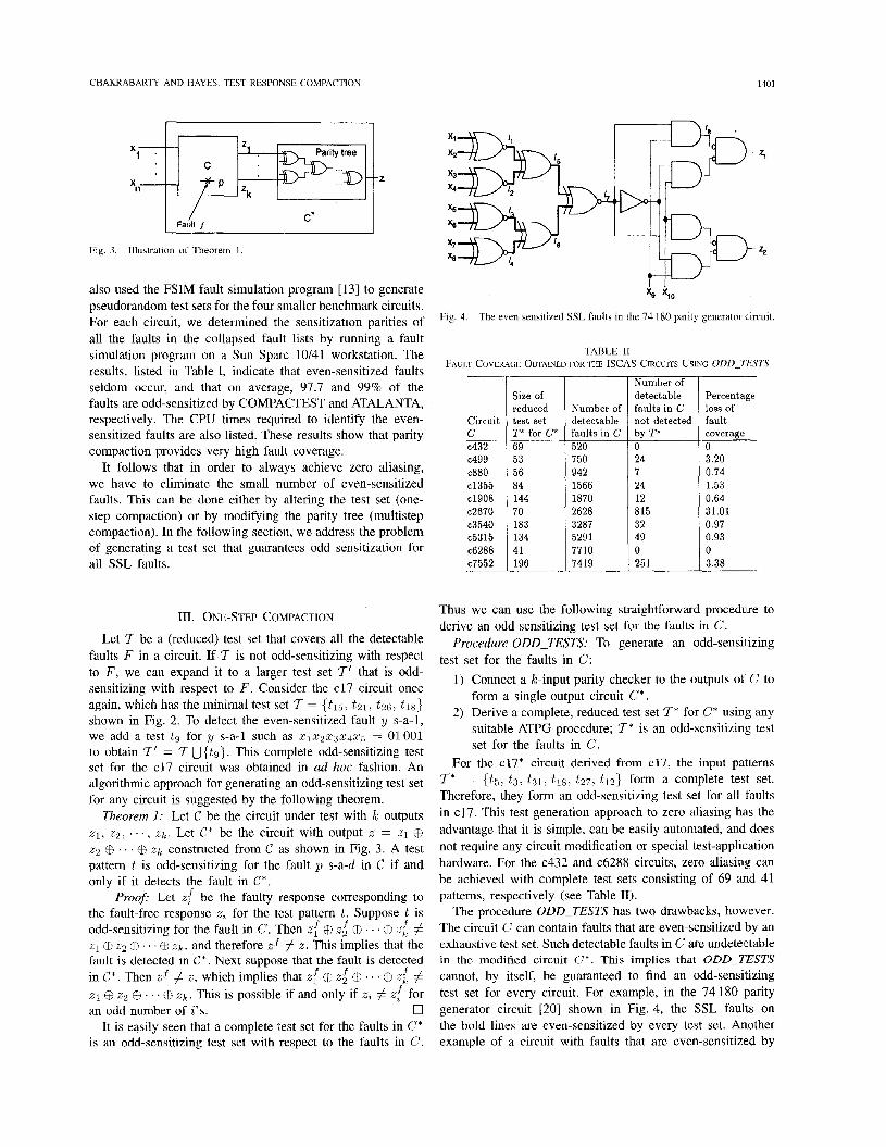
Fig. 3. Illustration of Theorem 1.
also used the FSIM fault simulation program [13] to generate pseudorandom test sets for the four smaller benchmark circuits. For each circuit, we determined the sensitization parities of all the faults in the collapsed fault lists by running a fault simulation program on a Sun Sparc 10/41 workstation. The results, listed in Table I, indicate that even-sensitized faults seldom occur, and that on average, 97.7 and 99% of the faults are odd-sensitized by COMPACTEST and ATALANTA, respectively. The CPU times required to identify the even- sensitized faults are also listed. These results show that parity compaction provides very high fault coverage.
It follows that in order to always achieve zero aliasing, we have to eliminate the small number of even-sensitized faults. This can be done either by altering the test set (one- step compaction) or by modifying the parity tree (multistep compaction). In the following section, we address the problem of generating a test set that guarantees odd sensitization for all SSL faults.
111. ONE-STEP COMPACTION
Let 7 be a (reduced) test set that covers all the detectable faults F in a circuit. If 7 is not odd-sensitizing with respect to F , we can expand it to a larger test set 7’ that is odd- sensitizing with respect to F . Consider the c17 circuit once again, which has the minimal test set I = (t15, t 2 1 , t26 , t ~ s } shown in Fig. 2. To detect the even-sensitized fault y s-a-1, we add a test f g for y s-a-1 such as 5 1 2 2 2 3 5 4 2 5 = 01001 to obtain 7’ = 7 U { t 9 } . This complete odd-sensitizing test set for the c17 circuit was obtained in ad hoc fashion. An algorithmic approach for generating an odd-sensitizing test set for any circuit is suggested by the following theorem.
Theorem 1: Let C be the circuit under test with k outputs z1, 2 2 , . . , z k . Let C* be the circuit with output x = 21 @ z2 @ . . . @ z k constructed from C as shown in Fig. 3. A test pattern t is odd-sensitizing for the fault p s-a-d in C if and only if it detects the fault in C*.
Proofi Let zf be the faulty response corresponding to the fault-free response x, for the test pattern t. Suppose t is odd-sensitizing for the fault in C. Then xf @ x2f @ . . . @ zf # z1 @ z2 @ . . . @ z k , and therefore xf # x. This implies that the fault is detected in C*. Next suppose that the fault is detected in C*. Then zf # z , which implies that zf @ zzf @ * . @ zf # XI @ z2 @ . 1 @ Zk. This is possible if and only if za # zf for an odd number of i ’ s . 17
It is easily seen that a complete test set for the faults in G* is an odd-sensitizing test set with respect to the faults in C.
Fig. 4. The even sensitized SSL faults in the 74 180 parity generator circuit.
TABLE I1 FAULT COVERAGE OBTAINED FOR THE ISCAS CIRCUITS USING oDD-Tl?sTs
Circuit C c432 c499 c880 c1355 c1908 c2670 c3540 c5315 c6288 c7552
Size of reduced test set ‘P for C* 69 53 56 84 144 70 183 134 41 196
Thus we can use the following straightforward procedure to derive an odd-sensitizing test set for the faults in C.
Procedure ODD-TESTS: To generate an odd-sensit izing test set for the faults in C:
1) Connect a k-input panty checker to the outputs of C to form a single-output circuit C* .
2) Derive a complete, reduced test set 7* for C* using any suitable ATPG procedure; I* is an odd-sensitizing test set for the faults in C.
For the c17* circuit derived from c17, the input patterns 7* = {ts, t 3 , t 3 1 , t 1 8 , t27 , tlz} form a complete test set. Therefore, they form an odd-sensitizing test set for all faults in c17. This test generation approach to zero aliasing has the advantage that it is simple, can be easily automated, and does not require any circuit modification or special test-application hardware. For the c432 and c6288 circuits, zero aliasing can be achieved with complete test sets consisting of 69 and 41 patterns, respectively (see Table 11).
The procedure ODD-TESTS has two drawbacks, however. The circuit G can contain faults that are even-sensitized by an exhaustive test set. Such detectable faults in C are undetectable in the modified circuit C*. This implies that ODD-TESTS cannot, by itself, be guaranteed to find an odd-sensitizing test set for every circuit. For example, in the 74 180 parity generator circuit [20] shown in Fig. 4, the SSL faults on the bold lines are even-sensitized by every test set. Another example of a circuit with faults that are even-sensitized by

1402 IEEE TRANSACTIONS ON COMPUTER-AIDED DESIGN OF INTEGRATED CIRCUITS AND SYSTEMS, VOL 15, NO 1 I , NOVEMBER 1996
so s1s2 53
C W Primary outputs of circuit under test
Fault -z
M-- Cll
Fig. 5. highlighted.
The 74 181 ALU circuit with lines having even-sensitized faults
every test set is the 74 181 ALWfunction generator [20]. The logic diagram and lines with even-sensitized faults are shown in Fig. 5.
The second problem with procedure ODD-TESTS is that most ATPG programs backtrack excessively when they en- counter a parity circuit with high fanin [2]. This was corrob- orated by experiments that we carried out by applying the procedure to some of the ISCAS 85 circuits. These experi- ments (Table 11) demonstrate that ODD-TESTS introduces a small loss of fault coverage. For example, the cl355 circuit contains only 8 even-sensitized faults for a particular reduced test set (Table I). However, when test generation was carried out for the c1355* circuit, no test was found for 24 faults, or 1.45% of the detectable faults. In the c499 circuit, there are 63 even-sensitized faults in Table I; we can reduce this number to 24 by applying ODD-TESTS, but we cannot eliminate aliasing altogether.
This motivates the need for design techniques that guarantee zero aliasing. Two such techniques, based on multiplexed parity trees, are presented in the next section.
IV. MULTISTEP COMPACTION
We now present multiplexed parity trees (MPT's), describe two MPT-based methods for zero-aliasing space compaction, and estimate the associated area overhead for the ISCAS benchmark circuits.
Multiplexed Parity Trees
A multiplexed parity tree M , shown in Fig. 6 combines the error propagation properties of multiplexers and parity trees to provide zero-aliasing space compaction. The lines
signature
I I ' . -- v < < k AND gates and control c l c2 c k inputs as needed
Fig. 6. A multiplexed parity tree M
21, 22, . . . , z k are the primary outputs of the circuit under test while the ci's are control inputs of M that select the 2;'s to be fed to the parity tree. The number of control inputs and AND gates v varies from 1 to k depending on the even-sensitized faults in the circuit under test. The output function z of M caube writtenasx = ( u ~ f c ~ ) x ~ ~ ( u ~ + c ~ ) z ~ ~ ~ ~ ~ ~ ( u ~ + c k ) z k , where u l , u2, . I . , arc are binary variables whose 0-1 assignments determine the structure of M . For example, let IC = 4, 'U 1, and a 3 = u4 = 0. This yields an MPT realizing the function z = X I CB z2 6€ e323 @ c4z4. We show later that zero aliasing can be achieved in (,U + 1) time- steps if E,"=, ai = w. Depending on the values assigned to the et 's and ai's, M can realize various parity and multiplexer functions, These special cases are described below.
1) If a decoder is used to generate the C L ' S , then M becomes a simple multiplexer that selects one of its data inputs 21, 2 2 , . . . , z k for direct connection to z .
2) If ?i = k then M is a multiplexer that selects one of the 2'" parity functions of z1, 2 2 , . . . , 2'".
3) If U ; = 1 for all i , i.e., all the AND gates are logically disconnected, then M is a simple parity tree with inputs z1, 2 2 , . " , 2'".
The values assigned to the control inputs of M affect error propagation through the parity tree. For example, if U = k , c1 = 1, and ci = 0 for all i # 1, then M propagates only those errors that appear on zl. Thus we can enhance error propagation by applying the test set I to the circuit under test multiple times, and assigning different sets of values to the c;'s in each time-step. We term this process multistep compaction. For example, if M is a simple multiplexer that connects one of the 2;'s to z , all error can be propagated through it in k time-steps. However, this leads to a k-fold increase in the test response length. We next describe two techniques for achieving zero aliasing based on MPT's and multistep compaction with only a small increase in the test response length.
2, a1 = u2
Output Selection
In this method, we exploit the fact that a test pattern usually sensitizes a fault to only a few primary outputs. Therefore,

CHAKRABAKTY AND HAYES: TEST RESPONSE COMPACTION
ISCAS bench- mark
1403
- Percentage Number Number Percentage overhead for overhead of of extra multiplexed p arity tree CPU for parity primary AND AND gates and I time
xPzl circuit c432 c499
tree outputs gates control logic Total (E& 4.17 7 2 2.18 6.35 1 15 15.19 32 15 27.37 42.56 1.59
we can obtain odd sensitization by selecting the outputs that are fed to the AND gates of M . (The remaining outputs are connected directly to the parity tree.) We first explain the basic idea using Fig. 6, and then present a practical design procedure. For a IC-output circuit, we use an MPT with IC AND gates and IC primary inputs c1, c2, . . . , C k . To ensure zero aliasing, we now test the circuit in I% + 1 phases. In phase 0, we set c; = 1 for 1 5 i 5 IC and apply the test set 7 for the original circuit. In phase i , we set c; = 0 and c j = 1 for j # i , and again apply 1. The control logic can be implemented either by a shift register arrangement as outlined in [5] , or by a demultiplexer driven by an external controller. It is easy to see that all faults in the circuit under test are now odd-sensitized. The faults that are detected by a parity tree are propagated to the output of the multiplexed parity tree when c; = 1, 1 5 i 5 IC. Faults that are even-sensitized are propagated by setting the ci’s to 0, one at a time. However, the length of the test response is now (IC + 1)171. This is comparable to the response length obtained if the space compactor of Fig. 1 is replaced by a IC-way multiplexer. We next give a systematic method for reducing the test response length.
A k-output circuit seldom needs IC extra AND gates since a fault is rarely sensitized to all the primary outputs. It suffices to consider only a subset of the primary outputs to which errors due to the even-sensitized faults are propagated. We view these outputs as test observation points that are fed to the AND gates of M . To identify them, we construct a sensitization table with columns denoting primary outputs z1, 2 2 , . . . , Z k and rows
Number of extra AND gates U 2 1 0 5 3 8 8 1 4 8
Percentage overhead for multiplexed p arity tree CPU AND gates and time control logic Total (sec) 2.18 6.35 1 .08 1.82 17.01 1.75 0 6.88 2.03 1.40 7.22 5.21 0.96 4.17 9.57 0.29 14.50 37.93 1.78 3.21 102.38 1.54 7.11 138.86 0.61 1.90 162.21 1.07 4.55 283.12
Even-sensitized
2 2 s-a-0, s-a-l z3 s-a-0, s-a-1 2 4 s-a-0, s-a-1 25 s-a-0, s-a-1 I 1 s-a-0, s-a-1 I2 s-a-0, s-a-1 I , s-a-0, s-a-l I4 s-a-0, s-a-l I5 s-a-0, s-a-l
faults
e880 c1355 c1908 c2670 c3540 c5315 c6288 c7552
Primary outputs
1 1 1 1 0 1 1 0 0 1 1 0 1 1 1 1 0 1 1 0 0 1 1 0 0 1 1 0 0 1 1 0 0 1 1 0
21 22 23 24
6.88 5.82 3.21 14.21 1.45 5.57 1.29 3.48
26 32 25 140 22 123 32 108
0 3 3 8 9 10 18 10
0 1.40 0.96 2.32 2.00 1.54 2.76 1.07
6.88 7.22 4.17 16.53 3.43 7.11 4.05 4.55
2 03 5 21 9 57 31.44 915.98 120.91 1!59.53 249.36
Number of primacy outputs 7 32 26 32 25 140 22 123 32 108
denoting the even-sensitized faults f i , f 2 , . e + , f m . The entry in the ith row and j th column is 1 if and only if fault fi is sensitized to output zJ by some test pattern in the test set 7. We use the sensitization table to find a (minimal) sensitization cover, i.e., a (minimal) set of primary outputs to which every fault is sensitized. We then introduce AND gates and control inputs in the multiplexed parity tree corresponding to the lines in the sensitization cover.
Consider the example circuit of Fig. 7(a), where the sensi- tization table for an exhaustive test set is shown in Fig. 7(b). The minimal cover for this table is either ( 2 2 ) or {z3},
from which we select { z 3 } . In general, the problem of find- ing the optimal sensitization cover C is equivalent to the NP-hard set covering problem [6]. We have implemented a fast, heuristic covering procedure FIND-COVER which is described in Fig. 8. Tables Ill and IV present the results of applying FIND-COVER to the ISCAS benchmark circuits for reduced and pseudorandom test sets. (The number of test patterns is listed in Table I.) The area overhead is calculated using the weighted gate count metric, and includes the cost of the multiplexed parity tree as well as the logic required to generate its control inputs. The total overhead is less than 8% for most circuits, and for many, especially the larger ones, it is less than 5%. The experimental results also show that the overhead depends on the choice of the test set.
The test response length for output selection is (IC( + 1)171, which is considerably shorter than (IC + 1)ITl. A key advantage of this method is that the circuit under test does not have to be modified, therefore it does not introduce any performance degradation for normal operation. We next

1404 IEEE TRANSACTIONS ON COMPUTER-AIDED DESIGN OF INTEGRATED CIRCUITS AND SYSTEMS, VOL. 15, NO. 11, NOVEMBER 1996
Procedure FIND-COVER {To find a near-minimal sensitization cover begin
remove-zero-columns(); {Remove all columns of t h e sensitization tab le with only zero entries} while not-al l - rows-removed() do begin
for i , j = 1 to number-of-columns do if d o m i n a t e s ( i , j ) then {dominates ( i , j ) = 1 if column i dominates column j }
remove-column( j ) ; IC := max-column() ; {select column IC with t h e largest number of 1's) select-column( I C ) ; for a = 1 to number-of-rows do
if sensitization-table[i][k] = 1 then remove-row( i);
remove-column(k); end
end
Fig. 8. Procedurc for finding a sensitization cover.
Procedure FANOUTJNSERTION {To add fanout branches to eliminate even-sensitization} begin Q := 4; {Q is initially empty} R := { (I1 , [z, . . . , I j )} ; { R is the set of chains} while R # 4 do begin
Select a chain (11, ..., l j ) from R; Q := Q u l j ; {Add the maximal element 13 to Q } for each chain of R of the type ( l j l , I; , , . . . , l j ) do
R := R - ( l j l , ..., Ij); {Remove chains with maximal element 13) end for each li E Q do
Create a fanout branch from 1; to an extra AND gate with a control input c;; end
Fig. 9. The fanout insertion procedure.
TABLE IV LOGIC OVERHEAD FOR OUTPUT SELECTION USING PSEUDORANDOM TEST SETS - ISCAS bench- mark circuit c432 c499 c880 e6288
~
~
of extra
15.19 6.88 26 1.29 32
Percentage overhead for
AND gates and time
0.61
describe a different MPT-based technique for zero aliasing which sometimes requires less hardware overhead than output selection.
Funout Insertion: All SSL faults in a fanout-free circuit are odd-sensitized because each fault must be sensitized to the only available primary output. Hence, fanout is a necessary condition for even sensitization. This suggests that we can ensure sensitization of all faults to an odd number of primary outputs by systematically inserting fanout branches in the circuit to eliminate even sensitization. These fanout branches form extra test observation points that are AND-ed with the control inputs in M . Thus the number of AND gates and control inputs in M equals the number of such additional test observation points.
Let L 1 (11. 1 2 , . . . , I & } be the set of all lines with even- sensitized faults in the circuit. We define a partial ordering on the lines in L as follows: I , dominates l,, denoted 1, 5 l,, if
all paths from 1.i to all primary outputs pass through I,. For example, in the 74188 circuit of Fig. 4, 21 I 25 but 21 -$ 28.
(Note that 5 is not the usual level-ordering relation.) We next group the lines in L into chains of the form ((11, Zz j . . . l j ) } such that 11 5 1 2 . . . 5 1,. Let R = ((11, 1 2 , . . . , l j ) } be the set of chains thus formed. For the example circuit of Fig. 4, L = {xl, x 2 , . " , X 8 , 11, 1 2 , . . . , 27) and R = {(xl, 11 , 1 5 :
171, ( 2 2 , l i , I5, 17) : ( 2 3 , 12, 1 5 , l7), ( 2 4 , 12 , l5, 17), (zsl 13,
A procedure FANOUT-INSERTION for adding fanout branches is given in Fig. 9, and applied to the 74 180 circuit in Fig. 10. It selects the maximal element of each dominance chain, i.e., it forms the smallest set Q of lines such that every line in the circuit is dominated by at least one line in this set. If IQ1 = U, we add v fanout branches, U two-input AND gates, and U auxiliary primary outputs to the circuit. Even-sensitization is now eliminated if the modified circuit is tested in v + 1 steps. In step 0, we set e1 = e2 = . . . = c, = 0 and apply the test set 7 for the original circuit. In each subsequent step i (1 5 i 5 v), we set c1 = . . . = cipl = c ; + ~ = . . . = c,, = 0, ci = 1, and apply 7 . The control logic can be implemented either by a shift register arrangement as in the output selection method. The test application time and response length are increased by a factor of v. However, as shown in Tables V and VI, v is small for most of the ISCAS circuits, so the increase in the test response length is reasonable.
15, 17)3 (z5: 13, I S , 1 7 ) , ( 2 7 , 14, 15, 17)' ( 2 8 , 24, 25, l 7 ) ) .

CHAKRABARTY AND HAYES: TEST RESPONSE COMPACTION
X
x,
I405
zi Multiplexed parity tree
M
2i
x, 30 BEg-=D- c1 - 5
Fig. 10. Application of FANOUT~INSEKTZON to thc 74 180 circuit
ISCAS bench- mark circuit c432 c499 c880 c1355 c1908 0.670 c3540 c5315 e6288 c7552
Percentage Number Percentage overhead for
for parity AND AND gates & Exclusive-or time tree gates U control logic gates Total (sec) 4.17 4 6.97 6.25 13.22 1.13 15.19 38 100 25.00 125.00 1.57 6.88 0 0 6.88 6.88 2.03 5.82 1 0.40 6.01 6.41 5.22 3.21 1 0.28 3.34 3.62 9.57 14.21 11 3.78 14.92 18.70 31.43 1.43 1 0.14 1.49 1.63 97.00 5.57 70 15.35 7.21 22.56 144.57 1.29 7 0.55 1.46 2.01 159.52 3.48 1 0.07 3.51 3.58 249.25
overhead of extra multiplexed parity tree CPU
- ISCAS bench- mark circuit c432 c499 c880 e1355 c1908 c2670 c3540 c5315 c6288 c7552
-
-
ISCAS Percentage Number Percentage overhead for
mark for parity AND AND gates & I Exclusive-or I bench- overhead of extra multiplexed parity tree
gates U
14.21 1.43 5.57 34 1.29 3.48
CPU time
(a)
Percentage overhead for multipl
AND gates & control logic 5.23 15.79 0 0.40 0.28 0.37 0.14 7.67 0.08 0.07
~-
ed parity trei Exclusive-or gates 6.25 17.15 6.88 6.01 3.34 14.31 1.49 7.12 1.33 3.51
__
Total 11.48 32.94 6.88 6.41 3.62 14.68 1.63 14.79 1.41 3.58
-
-
CPU time
1.14 1.49 2.09 5.19 9.60 37.83 102.33 141.37 163.01 290.17
-
-
circuit c432 c499 e880 c6288
~
~
15.19 15.79 6.88 10 15.13 1.29 0.08
gates
17.15
We next show that FANOUT-INSERTION ensures zero aliasing in the space compaction process. Every fault that is odd-sensitized in the original circuit generates an error that is propagated to the output of the space compactor when cJ = 0, for 1 5 j 5 71. Consider a fault ,f = 1 s-a-d that is even- sensitized in the original circuit. Suppose 1 5 I , , where 1,
s-a-d; is also even-sensitized and 1; E &. (If I is not dominated by any other line, then 1; = 1.) If t E 7 is a test for f , then it sensitizes f to an odd number of primary outputs i n the modified circuit when c; = 1 and cj = 0 for j # 1;. Also, the addition of the fanout branches does not create any even- sensitized faults. Suppose a fanout branch is inserted at 1 j .
Consider a line 1; such that there is a path from Z r to a primary output via l j . If a fault on 1; is odd-sensitized when there is no fanout branch then it remains odd-sensitized in the modified circuit since c j can be set to 0.
For most circuits, the size of Q , the set of maximal lines in the chains, is small, and therefore the hardware overhead to ensure zero aliasing is modest. We have applied FANOUT-INSERTION to the ISCAS combinational bench- mark circuits using the reduced test sets of Table I. The results for test sets generated by COMPACTEST, including the total CPU time for the identification of even-sensitized faults and fanout insertion, are given in Table V(a). The area overhead is estimated by the weighted gate count (gate count multiplied by the average fanin) assuming a 5-gate realization of a flip-flop [20]. The overhead for the multiplexed panty tree consists of a ( k + w)-input parity tree, v 2-input AND gates, and the logic required to generate the control signals c1, c2, . * . , e,. The overhead figures for a k-input parity tree are also listed. For four of the benchmark circuits--c1908, ~3540 , c6288, and c7552-the total overhead is very low (less than 5%). For two other circuits, c880 and ~ 1 3 5 5 , the total overhead is less than 10%.
Although the overhead is very high for the c499 circuit due to its relatively high fraction of even-sensitized faults, it can be reduced by a different choice of the test set. To demonstrate this, we applied FANOUT-INSERTION to the ISCAS circuits with test patterns generated by ATALANTA. The results, shown in Table V(b), indicate that the overhead does indeed depend on the choice of the test set. In all cases, the larger test sets generated by ATALANTA reduced th'a area overhead. In the c499 case, ATALANTA produced more tests, but the overhead for fanout insertion dropped from over 100% to less than 33%.
We also applied FANOUT-INSERTION to some IlSCAS circuits for pseudorandom test sets generated using FSIM. The
1406 IEEE TRANSACTIONS ON COMPUTER-AIDED DESIGN OF INTEGRATED CIRCUITS AND SYSTEMS, VOL. 15, NO. 11, NOVEMBER 1996
I s-a-1
/ 1 s-a-0
\ IC ,
T
I I
Signature
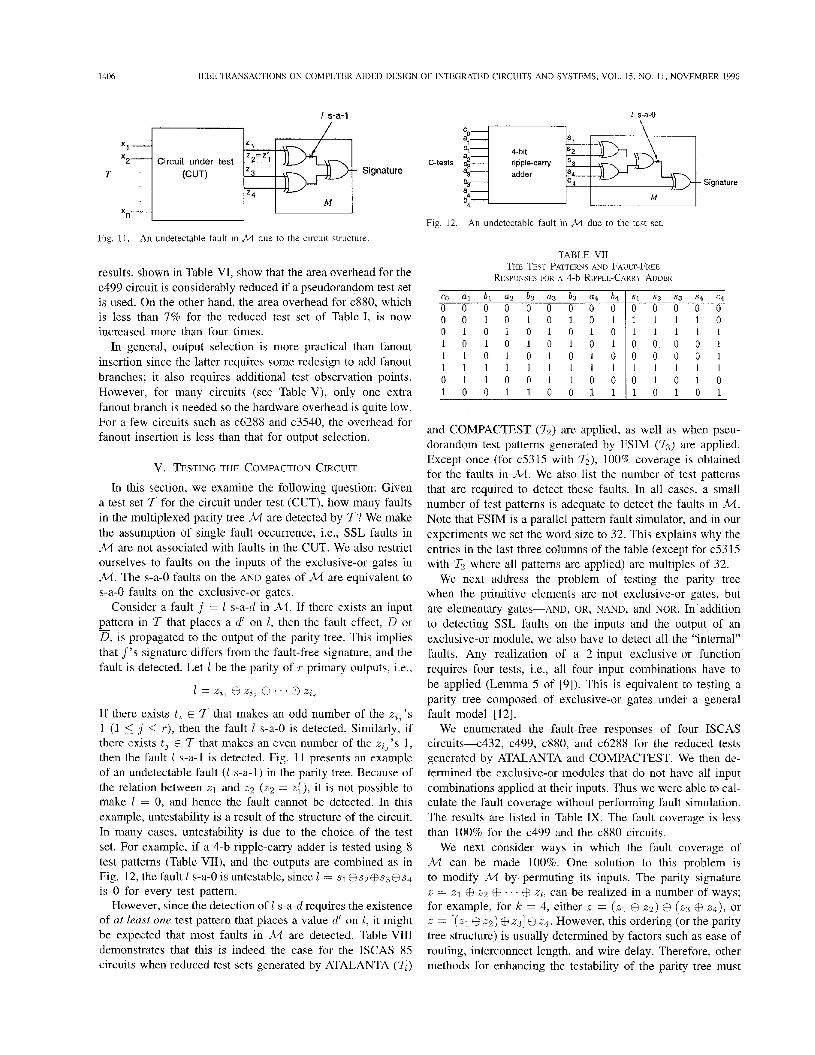
Fig. 11. An undetectable fault in M due to the circuit structure.
results, shown in Table VI, show that the area overhead for the c499 circuit is considerably reduced if a pseudorandom test set is used. On the other hand, the area overhead for c880, which is less than 7% for the reduced test set of Table I, is now increased more than four times.
In general, output selection is more practical than fanout insertion since the latter requires some redesign to add fanout branches; it also requires additional test observation points. However, for many circuits (sec Table V), only one extra fanout branch is needed so the hardware overhead is quite low. For a few circuits such as c6288 and c3540, the overhead for fanout insertion is less than that for output selection.
v. TESTING THE COMPACTION CIRCUIT
In this section, we examine the following question: Given a test set 7 for the circuit under test (CUT), how many faults in the multiplexed parity tree M are detected by I? We make the assumption of single fault occurrence, i.e., SSL faults in M are not associated with faults in the CUT. We also restrict ourselves to faults on the inputs of the exclusive-or gates in M . The s-a-0 faults on the AND gates of M are equivalent to s-a-0 faults on the exclusive-or gates.
Consider a fault f = 1 s-a-d in M . If there exists an input pattern in I that places a d’ on 1, then the fault effect, D or D , is propagated to the output of the parity tree. This implies that f ’s signature differs from the fault-free signature, and the fault is detected. Let 1 be the parity of T primary outputs, i.e.,
-
1 = z i , @ zi2 @I . . . @I zzv
If there exists t; E 7 that makes an odd number of the xi,’s 1 (1 5 J’ 5 T ) , then the fault 1 s-a-0 is detected. Similarly, if there exists ti E 7 that makes an even number of the z i J ’ s 1, then the fault 1 s-a-1 is detected. Fig. 11 presents an example of an undetectable fault (1 s-a-1) in the parity tree. Because of the relation between z1 and z2 (22 = z i ) , it is not possible to make I = 0, and hence the fault cannot be detected. In this example, untestability is a result of the structure of the circuit. In many cases, untestability is due to the choice of the test set. For example, if a 4-b ripple-carry adder is tested using 8 test patterns (Table VII), and the outputs are combined as in Fig. 12, the fault 1 s-a-0 is untestable, since 1 = s1@s2@s3@s4 is 0 for every test pattern.
However, since the detection of 1 s-a-d requires the existence of at least one test pattern that places a value cl’ on I , it might be expected that most faults in M are detected. Table VI11 demonstrates that this is indeed the case for the ISCAS 85 circuits when reduced test sets generated by ATALANTA (z)
4-bit ripple-carry adder
L M
Fig. 12. An undetectable fault in M due to the test set.
TABLE VI1 THE TEST PATTERNS AND FAULT-FREE
RESPONSES FOR A 4-b RIPPLE-CARRY ADDER
Signature
0 0 1 0 1 0 1 0 1 0 1 0 1 0 1 0 1 0 1 0 1 0 1 0 1 0 1 1 1 0 1 0 1 0 1 0 1 1 1 1 1 1 1 1 1 0 1 1 0 0 1 1 0 0
1 1 1 1 0 1 1 1 1 1 0 0 0 0 1 0 0 0 0 1 1 1 1 1 1 0 1 0 1 0
1 0 0 1 1 0 0 1 1 1 1 0 1 0 1
and COMPACTEST ( 7 2 ) are applied, as well as when pseu- dorandom test patterns generated by FSIM ( 7 3 ) arc applied. Except once (for c5315 with 7 2 ) , 100% coverage is obtained for the faults in M . We also list the number of test patterns that are required to detect these faults. In all cases, a small number of test patterns is adequate to detect the faults in M . Note that FSIM is a parallel pattern fault simulator, and in our experiments we set the word size to 32. This explains why the entries in the last three columns of the table (except for c53 15 with I2 where all patterns are applied) are multiples of 32.
We next address the problem of testing the parity tree when the primitive elements are not exclusive-or gates, but are elementary gates-AND, OR, NAND, and NOR. In addition to detecting SSL faults on the inputs and the output of an exclusive-or module, we also have to detect all the “internal” faults. Any realization of a 2-input exclusive-or function requires four tests, i.e., all four input combinations have to be applied (Lemma 5 of [9]). This is equivalent to testing a parity tree composed of exclusive-or gates under a general fault model [12].
We enumerated the fault-free responses of four ISCAS circuits-c432, c499, c880, and c6288 for the reduced tests generated by ATALANTA and COMPACTEST. We then de- termined the exclusive-or modules that do not have all input combinations applied at their inputs. Thus we were able to cal- culate the fault coverage without performing fault simulation. The results are listed in Table IX. The fault coverage is less than 100% for the c499 and the c880 circuits.
We next consider ways in which the fault coverage of M can be made 100%. One solution to this problem is to modify M by permuting its inputs. The parity signature z = z1 CE 22 @ . . . @ z k can be realized in a number of ways; for example, for k = 4, either x = (xl @ z2 ) @ ( z3 @ zq), or z = [(XI @ 2 2 ) @ 231 @ 24. However, this ordering (or the parity tree structure) is usually determined by factors such as ease of routing, interconnect length, and wire delay. Therefore, other methods for enhancing the testability of the parity tree must

CHAKRABARTY AND HAYES: TEST RESPONSE COMPACTION 1407
ISCAS bench- mark circuit c432 c499 c880 c1355 c1908 c2670 c3540 e5315 c6288 c7552
No. of No. of faults Percentage of No. of patterns faults No. of test detected by the faults detected by required for in patterns applied the test patterns test patterns fault detection M 11 7 2 13 TI 7 2 'T; II 1 2 'T; TI 1 2 1 3 12 48 54 512 12 12 12 100 100 100 32 32 32 62 59 56 1024 62 62 62 100 100 100 32 32 32 50 34 62 3616 50 50 50 100 100 100 32 32 128 62 95 87 5024 62 62 62 100 100 100 32 32 32 48 129 128 6016 48 48 48 100 100 100 32 32 32 278 75 127 100000 278 278 278 100 100 100 32 64 128 42 113 172 12000 42 42 42 100 100 100 32 32 32 244 59 137 GO16 244 234 244 100 95 90 100 32 137 128 62 23 40 64 62 62 62 100 100 100 32 32 32 214 88 236 20000 214 214 214 100 100 100 64 64 128
TABLE IX
GENERATED USING COMPACTEST (7 , ) AND ATALANTA NUMBER OF FAULTS IN ,2/1 DETECTED BY REDUCED TEST SETS
(I,) FOR (a) AND-OR REALIZATION OF AN EXCLUSIVE OR GATF AND (b) 4-NAND REALIZATION OF AN EXCLUSIV~ OK GATF
ISCAS I No. of I No. of faults I Pe rcentage of benchmark circuit c432
faults in detected fa ults detected parity tree TI 1 1 2 7' I 7 2 120 120 I 120 100 I 100
c499 620 600 572 96.67 92.26 c880 498 498 99.60 99.60 c6288 1 :i: 1 620 I 620 I 100 1 100
(a)
c499 682 c880 550 c6288 682
be used. One such method is to add patterns to the given test set for the circuit.
The parity tree M can be tested under the general fault model with only four tests [12]. However, the inputs to M are the outputs of the circuit under test, hence it may not be possible to apply these tests. It appears that the more the logical dependence between the primary outputs, the harder it is to apply the tests to M . The justification procedure of the D-algorithm can be used to find a suitable assignment to the primary inputs of the CUT, if one exists. Satisfiability-based methods can also be used, but they require that an algebraic representation be extracted from the CUT.
Yet another way of ensuring full testing of M is suggested by a recent theorem on fault detection in parity checkers [lo], which states that a k-input parity tree can be completely tested for all stuck-line faults by the following k + 1 patterns: (00. . .0 , 10 . . 0, 010. . .0, e I . . 0 . 01). These test patterns can be easily generated by an on-chip cyclic shift register and applied to the parity tree as shown in Fig. 13. However, the shift register and multiplexer can have a significant impact on the hardware overhead. For example, the associated overhead for c499 is excessive (125%) while for c432, it is a significant
Fig. 13. On-chip test generation For .M
11%. The overhead tends to decrease for larger circuits; for c6288 it is negligible (0.2%) and it is only 4% for c7552.
VI. CONCLUSION
We have presented an efficient zero-aliasing space com- paction approach for multiple-output circuits based on mul- tiplexed parity trees. We exploit the fact that typical ATPG programs sensitize SSL faults to an odd number of primary outputs, a property we call odd sensitization. We have demon- strated that test generation can often be used to achieve zero-aliasing one-step compaction with parity trees. Pin al- ternative approach to achieving zero aliasing is mulltistep (sequential) compaction, which is based on multiplexed parity trees. We have developed two techniques-output selection and fanout insertion-that achieve multistep transparency. We have shown that the associated hardware overhead is moderate for the ISCAS combinational benchmark circuits. An added benefit of this approach is that very high fault coverage is obtained for faults in the compaction circuit.
The results presented in this paper raise a number of open questions. We have seen that for some circuits such ,as the 74 180 parity checker and the 74 181 ALU, zero aliasing with parity trees can only be achieved via multistep compaction. However, for others such as c432, zero aliasing can also be achieved via one-step compaction by altering the test set. For the latter circuits, can we find efficient algorithmic techniques for constructing zero-aliasing test sets by adding test patterns to a reduced test set? Second, the logic overhead foir both one-step and multistep compaction methods depends on the choice of the test set. Can zero-aliasing test sets be designed
1408 IEEE TRANSACTlONS ON COMPUTER-AIDED DESlGN OF INTEGRATED CIRCUITS AND SYSTEMS, VOL. 1.5, NO. 11, NOVEMBER 1996
to reduce overhead, especially for circuits such as c499? We are currently investigating a two-pronged approach to the zero- aliasing problem that systematically combines test generation with the design of the multiplexed parity tree to reduce the
[19] B. Tsuji, A. Ivanov, and Y. Zorian, “Selecting programmable space compactors for BlST using genetic algorithms,” in Proc. 1994 Asiun Test Symp., 1994, pp. 233-241.
[20] The TTL Data Book. [21] Y. You and J. P. Hayes, “Implementation of VLSI self-testing by regular-
ization,” IEEE Trans. Cornpuler-Aided Design, vol. 8 , pp. 1261-1271, Jan. 1989.
Dallas: Texas Instruments, 1988, vol. 2.
area overhead.
ACKNOWLEDGMENT
We are grateful to Professor I. Pomeranz and Professor S. Reddy of the University of Iowa for providing us with COMPACTEST. We also thank Professor D. Ha of Virginia Tech. for making FSIM and ATALANTA available.
REFERENCES
P. H. Bardell, W. H. McAnney, and J. Savir, Built-in Testfor VLSZ: Pseudorandom Techniques. D. Brand, “Verification of large synthesized designs,” in Proc. 1993 Inr. Conj: Computer-Aided Design, 1993, pp. 534-537. F. Brglez and H. Fujiwara, “A neutral netlist of 10 combinational benchmark circuits and a target simulator in Fortran,” in Proc. 1985 Int. Symp. Circuits Syst., 1985, pp. 695-698. J. Broseghini and D. H. Lenhert, “An ALU-based programmable MISR/pseudorandom generator for a MC68HC 1 1 family self-test,” in Proc. 1993 Int. Test Cons, 1993, pp. 349-358. K. Chakrabarty and J. P. Hayes, “Elficient test response compression for multiple-output circuits,” in Proc. 1994 Int. Test Cons, 1994, pp. 501-5 10. T. H. Cormen, C. E. Leiserson, and R. L. Rivest, Introduction to AZgorithms. H. Fujiwara and A. Yamamoto, “Parity-scan design to reduce the cost of test application,” ZEEE Trans. Computer-Aided Design, vol. 12, pp. 1604-1611, Oct. 1993. M. C. Hansen and J . P. Hayes, “High-level test generation using physically-induced faults,” in Proc. 1995 VLSI Test Symp., pp. 20-28. J. P. Hayes, “On realizations of Boolean functions requiring a minimal
New York: Wiley, 1987.
Cambridge, MA: MIT Press, 1990.
. - or near-minimal number of tests,” IEEE Truns. Comput., vol. 20, pp. 1506-1513, Dec. 1971. W.-B. Jone and C.-J. Wu, “Multiple fault detection in parity checkers,” IEEE Truns. Cornput., vol. 43, pp. 1096-1099, Sept. 1994. M. Karpovsky and P. Nagvajara, “Optimal time and space compression of test responses for VLSI devices,” in Proc. 1987 Int. Test CO@, 1987, pp. 523-529. W. H. Kautz, “Testing for faults in combinational logic arrays,” in Proc. 8lh Ann. Switching und Automata Theory Symp., 1967, pp. 161-174. H. K. Lee and D. S. Ha, “An efficient forward fault simulation algorithm based on the parallel pattern single fault propagation,” in Proc. 1991 Int. Test Conf, 1991, pp. 946-955. Y. K. Li and J. P. Robinson, “Space compaction methods with output data modification,” ZEEE Truns. Computer-Aided Design, vol. 6 , pp. 290-294, Mar. 1987. B. T. Murray, “Hierarchical testing using precomputed tests for mod- ules,” Ph.D. dissertation, Univ. Michigan, 1994. I. Pomeranz, L. N. Reddy, and S. M. Reddy, “COMPACTEST: A method to generate compact test sets for combinational circuits,” in Proc. 1991 Int. Test Con$, 1991, pp. 194-203. 1. Pomeranz, S . M. Reddy, and R. Tangirala, “On achieving zero aliasing for modeled faults,” in Proc. 1992 Eur. Design Automation C m t , Mar. 1992, pp. 291-299. S. M. Reddy, K. K. Saluja, and M. G. Karpovsky, “A data compression technique for built-in self-test,” IEEE lruns. Computers, vol. 37, pp. 1151-1156, Sept. 1988.
1221 Y . Zorian and A. lvanov, “Programmable space compaction for BIST,” in Proc.. 1993 lnt. Symp. Fault-Toleranl Computing, 1993, pp. 340-349.
Krishnendu Chakraharty (S’92-M’96) received the B Tech degree from the lndian lnstitute of Technology, Kharagpur, in 1990, and the M S E and Ph.D. degrees from the University of Michigan, Ann Arbor, in 1992 and 199.5, respectively, all in computer science and engineering
While at the University of Michigan, he was a re- yearch assistant with the Advanced Computer Archi- tecture Laboiatory of the Department of Electncal Engineering and Computer Science Currently, he is an Assistant Professor of electrical and computer
engineering at Boston Univer9ity His research interests are in computer-aided design of VLSI circuits and systems, testing, deyign verification, and fault- tolerant computing
Dr Chakrabarty is a member of ACM and Sigma Xi
John P. Hayes (S’67-M’70-SM’81-F’85) received the B.E. degree from the National University of Ireland, Dublin, in 1965, and the M.S. and Ph.D. degrees from the University of Illinois, Urbana- Champaign, in 1967 and 1970, respectively, all in electrical engineering.
While at the University of Illinois, he participated in the design of the ILLIAC 111 computer. In 1970 he joined the Operations Research Group at the Shell Benelux Computing Center in The Hague, where he worked on mathematical programming. From
1972 to 1982 he was a faculty member of the Departments of Electrical Engineering-Systems and Computer Science of the University of Southern California, Los Angeles. He joined the University of Michigan in 1982. He was the founding director of the University of Michigan’s Advanced Computer Architecture Laboratory. Currently, he is a Professor of electrical engineering and computer science at the University of Michigan, Ann Arbor, where he teaches and does research in the areas of computer architecture; computer-aided design, verification, and testing; VLSI design; and fault- tolerant embedded systems. He is the author of numerous technical papers and five books, including Computer Architecture und Organization (2nd ed., McGraw-Hill, 1988), Hierarchicul Modelingjor VLSI Circuit Testing (Kluwer, 1990; coauthored with D. Bhattacharya), and Introduction io Digiiul Logic Design (Addison-Wesley, 1993).
Dr. Haycs was Technical Program Chairman of the 1977 International Conference on Fault-Tolerant Computing, Los Angeles, and the 199 1 lnterna- tional Computer Architecture Symposium, Toronto. He has served as editor of various technical journals, including thc IEEE TRANSACTIONS ON PARALLEL AND DISTRIBUTED SYSTEMS and the Journal of Electronic Testing. He is a member of ACM and Sigma Xi.