test report number: etra71127, rev. b reference standard: en 55011: 2007… · 2019. 5. 14. · the...
TRANSCRIPT

Test Report Number: ETRA71127, Rev. B
Reference Standard: EN 55011: 2007, Class A, Group 1, FCC Part 18
Date of Test: 14 November 2007
Date of Report: 15 January 2008
Product Name: IonCleanse Premier
Model Number: IonCleanse Premier
Serial Number: 08000
Manufacturer: A Major Difference
Representative: Neill Moroney
Report Type: Radiated and Conducted Emissions
Test Result: Compliant
Approved By:
The results contained within this report relate only to the product tested.This report shall not be reproduced, except in full, without written approval from EMC Integrity, Inc.
This report must not be used by the client to claim product certification, approval, or endorsement by EMC Integrity,NEMKO, NVLAP, NIST, or any agency of the federal government.
Rev. B Total Pages: 58

EMC INTEGRITY, INC. Test Report # ETRA71127, Rev. B
Prepared for:
A Major Difference 2950 S Jamaica Ct. Suite 300
Aurora, CO 80014 Phone: 303-755-0112 Fax: 303-755-3022
Customer Representative:
Neill Moroney Vice-President
Tested at:
EMC Integrity, Inc. 1736 Vista View Drive
Longmont, Colorado 80504
Tested by:
Tom Wittig Lead Technician
Report Prepared by:
Mary Burback
Office Manager
Report Approved by:
Chris Poore Laboratory Manager
Revision Description of Revision Date: Rev. - Initial Release 17 December 2007 Rev. A Changed name of manufacturer from Stargate
International to “A Major Difference” 10 January 2008
Rev. B Changed description of device from “body detoxification” to “vitality enhancement system.”
15 January 2008
Rev. B Total Pages: 58 2

EMC INTEGRITY, INC. Test Report # ETRA71127, Rev. B
TABLE OF CONTENTS
Section # Test Summary .......................................................................................................1.0 Test Environment..................................................................................................2.0 Radiated Emissions ...............................................................................................3.0 Conducted Emissions............................................................................................4.0 AC Power Line Flicker .........................................................................................5.0
LIST OF APPENDICES Radiated Emissions Test Data ......................................................... APPENDIX A Conducted Emissions Test Data, 115 Vac/60 Hz ........................... APPENDIX B Conducted Emissions Test Data, 230 Vac/50 Hz ........................... APPENDIX C AC Power Line Flicker Test Data ................................................... APPENDIX D Product Data Sheet ........................................................................... APPENDIX E EMI Test Log......................................................................................APPENDIX F Laboratory Accreditations...............................................................APPENDIX G
Rev. B Total Pages: 58 3

EMC INTEGRITY, INC. Test Report # ETRA71127, Rev. B
1.0 TEST SUMMARY 1.1 Product Description The unit under test (UUT) was the IonCleanse Premier. The Serial Number tested was 08000. This product is manufactured by A Major Difference located in Aurora, Colorado. It is a vitality enhancement system. A more complete description of this product may be found in the Product Data Sheet, located in Appendix E of this report. 1.2 Purpose This report documents the test efforts performed on the IonCleanse Premier to verify compliance to the Class A, Group 1 limits of EN 55011: 2007 and FCC Part 18. This was a formal qualification test and was conducted on 14 November 2007. 1.3 Test Standards Used The emission limits applied to the product tested are defined in EN 55011: 2007, which is the product family standard for Industrial, Scientific and Medical (ISM) equipment. The UUT was set up as specified in ANSI C63.4: 2003. The normative references of this standard define the test methods used for the emissions testing. These standards are contained in Table 1-1.
Table 1-1
CISPR 11: 2004 + A2: 2006 EN 55011: 2007 CISPR 22: 2006 EN 55022: 1998 + A1 (2000) + A2 (2003) CFR 47, FCC Parts 15 & 18 EN 61326: 1997 + A1: 1998 + A2: 2001 + A3: 2003 EN 60601-1-2: 2001 EN 55103-1: 1997 EN 61000-6-3: 2001 EN 61000-6-4: 2001 ANSI C63.4: 2003 CISPR 16-1: 2002
1.4 Test Results The UUT complied with the Class A, Group 1 emission requirements defined by EN 55011: 2007, and with FCC Part 18. The UUT also complied with the requirements for AC power line flicker, as defined by IEC and EN 61000-3-3. Test data is contained in the appropriate appendices of this report. 1.5 Modifications Required for Compliance No modifications were required for compliance with emissions.
Rev. B Total Pages: 58 4

EMC INTEGRITY, INC. Test Report # ETRA71127, Rev. B
2.0 TEST ENVIRONMENT 2.1 Radiated Emissions Test Site Radiated emissions testing was performed at a distance of 10-meters in a semi-anechoic 10-meter chamber. This chamber is calibrated annually and meets the volumetric site attenuation requirements of ANSI C63.4: 2003 at a distance of 10 meters. For measurements from 30 MHz to 2 GHz, a biconilog antenna is used in conjunction with a high-gain, low-noise preamplifier. This is connected to an HP 8566B spectrum analyzer with an HP 85650A Quasi-Peak (QP) Adapter, via an HP 85685 RF Preselector. Radiated emissions testing is broken into two parts: pre-scan and QP/maximization. Pre-scanning a product from 30 MHz to 2 GHz consists of measuring peak emissions from eight radials (every 45 degrees), at four antenna heights (1 m, 2 m, 3 m and 4 m) for both antenna polarities. Data is recorded in a graph showing amplitude vs. frequency of the emissions, and frequencies for QP/maximization are chosen based on this graph. The procedure for maximizing emissions is as follows:
1. The analyzer is tuned to the frequency associated with the emissions having the least margin.
2. The turntable and antenna mast are moved to the location where the maximum emission was measured during the pre-scan.
3. Both are then oriented such that the maximum emission is obtained. 4. Cables on the UUT are manually manipulated to achieve the maximum emission. 5. The turntable and antenna mast are then re-adjusted to ensure a maximum reading. 6. If the signal in question is less than 1 GHz, quasi-peak detection is performed on the
signal for a minimum of 10 seconds. For signals greater than 1 GHz, video averaging is performed.
7. Turntable/antenna mast maximization and QP detection are performed on all other signals within 6 dB of the limit. In the event that there are not six signals within 6 dB of the limit, the highest six signals are maximized. This ensures that a minimum of six signals are maximized and appear in the final data table.
2.2 Conducted Emissions Test Site Conducted emissions testing was performed on a 10’ by 10’ ground plane, which is bonded to the wall of the 10-meter chamber, using its wall as the vertical coupling plane. Line impedance stabilization networks (LISNs) was inserted in series with both the UUT and the support equipment. The LISNs used were standard 50 Ω/50 uH LISNs which complied with the requirements of ANSI C63.4. These LISNs are calibrated annually for both complex impedance and insertion loss. Measurement equipment used was an HP 8566B spectrum analyzer with an HP 85650A QP adapter. In addition, a transient limiter and a high-pass filter are used to protect the front-end of the receiver from transients and low-frequency noise, respectively.
Rev. B Total Pages: 58 5

EMC INTEGRITY, INC. Test Report # ETRA71127, Rev. B
2.3 Measurement Uncertainty The measurement uncertainty for EMC Integrity’s emissions test facility complies with the requirements defined in CISPR 16. The complete calculations of EMC Integrity’s measurement uncertainty is contained in an EMCI memo, which is available upon request. However, a summary of EMCI’s measurement uncertainty is given in Table 2-1.
Table 2-1
Test Requirement Actual Conducted Emissions 3.60 dB 3.04 dB Radiated Emissions – Horizontal Polarity 5.20 dB 4.67 dB Radiated Emissions – Vertical Polarity 5.20 dB 5.01 dB
Rev. B Total Pages: 58 6
EMC INTEGRITY, INC. Test Report # ETRA71127, Rev. B
3.0 Radiated Emissions 3.1 Summary of Test Results Radiated electric field emissions were measured on the UUT over the frequency range from 30 MHz to 1 GHz. The UUT was powered from 230 Vac/50 Hz, configured in its normal operating mode, and exercised continually during testing. Cables were oriented such that the maximum emission was achieved and quasi-peak detection was performed all signals (minimum of six) used in the final data table. Test result: Compliant Margin: 2.75 dB @ 96.444 MHz 3.2 Test Setup The UUT was set up in accordance with ANSI C63.4: 2003 and tested to the Class A, Group 1 limits specified in EN 55011 and FCC Part 18. 3.3 Special Configurations Not applicable. 3.4 Deviations from Test Procedures Not applicable. 3.5 Test Data See APPENDIX A for all test data sheets, test setup pictures and test equipment used.
Rev. B Total Pages: 58 7

EMC INTEGRITY, INC. Test Report # ETRA71127, Rev. B
4.0 Conducted Emissions 4.1 Summary of Test Results Conducted emissions were measured on the AC power input of the UUT over the frequency range from 150 kHz to 30 MHz. With the UUT configured in its normal operating mode, testing was performed with UUT powered from 115 Vac/60 Hz and 230 Vac/50 Hz. The input power to both the UUT and the support equipment was run through standard 50 Ω/50 uH line impedance stabilization networks (LISNs) which complied with the requirements of ANSI C63.4. Emissions were compared to both quasi-peak (QP) and average limits, with QP detection and averaging performed on the six highest signals. 115 Vac/60 Hz Test result: Compliant Margin: 13.85 dB @ 14.881 MHz 230 Vac/50 Hz Test result: Compliant Margin: 13.25 dB @ 6.209 MHz 4.2 Test Setup The UUT was set up in accordance with ANSI C63.4: 2003 and tested to the Class A, Group 1 limits specified in EN 55011 and FCC Part 18. 4.3 Special Configurations Not applicable. 4.4 Deviations from Test Procedures Not applicable. 4.5 Test Data See APPENDICES B and C for all test data sheets, test setup pictures and test equipment used.
Rev. B Total Pages: 58 8

EMC INTEGRITY, INC. Test Report # ETRA71127, Rev. B
5.0 EN 61000-3-3: 1995 + A1 (01) + A2 (03) + A3 (06), Power Line Flicker 5.1 Summary of Test Results Power line flicker from the UUT was measured on the system's AC power input. The power source was a 230 Vac/50 Hz source. Integral to the power source was the measurement hardware/firmware and flicker was recorded to the computer. Results are then imported via soft copy to the test data sheet. The UUT complied with the flicker requirements of EN 61000-3-3. 5.2 Test Setup The UUT was set up per EN 61000-3-3. 5.3 Special Configurations N/A 5.4 Performance Criteria Defined in EN 61000-3-3. 5.5 Deviations from Test Procedures N/A 5.6 Test Data See APPENDIX D for data sheets and test setup pictures. 5.7 Temperature and Humidity Temperature, relative humidity and barometric pressure are located in the header table for the EN 61000-3-3 test data sheet.
Rev. B Total Pages: 58 9

EMC INTEGRITY, INC. Test Report # ETRA71127, Rev. B
APPENDIX A
Radiated Emissions Test Data
Rev. B Total Pages: 58 10

EMC INTEGRITY, INC. Test Report # ETRA71127, Rev. B
Radiated Emissions, CISPR / EN 55011 Manufacturer: A Major Difference Project Number: A71127
Customer Representative: Neill Moroney Test Area: 10 Meter Model: IonCleanse Premier S/N: 08000
Standard Referenced: EN 55011: 2007 Date: November 14, 2007 Temperature: 22˚C Humidity: 25% Pressure: 844 mb
Input Voltage: 230Vac/50Hz
Configuration of Unit: Normal Operation Mode #1
Test Engineer: Tom Wittig A71127-11-RE.doc FR0100 Type Frequency
(MHz) Level
(dBuV) Transducer
(dB/m) Gain / Loss
(dB) Final
(dBuV/m) Azm(deg)/Pol/Hgt(m) Margin: EN55011
Class B Group 1 QP (dB)
QP 36.009 38.7 16.6 -29.7 25.7 6/V-Pole/1.00 4.34 QP 96.444 48.0 9.3 -30.0 27.2 132/V-Pole/4.00 2.75 QP 132.045 35.4 13.8 -29.8 19.4 138/V-Pole/2.98 10.56 QP 174.061 34.0 11.6 -29.4 16.1 148/V-Pole/1.20 13.86 QP 181.062 38.9 11.3 -29.5 20.8 123/V-Pole/1.20 9.24 QP 182.062 38.0 11.3 -29.5 19.8 131/V-Pole/1.30 10.21 QP 537.244 40.0 18.0 -29.2 28.8 114/V-Pole/4.00 8.17 The highest emission measured was at 96.444 MHz, which was 2.75 dB below the limit.
“Type” refers to the type of measurement performed. The type of measurement made is based on the requirements of the particular standard:
• PK = Peak Measurement
• QP = Quasi-Peak Measurement
• AV = Video Average Measurement
The “Final” emissions level is attained by taking the “Level” and adding the “Transducer” factor and the “Gain/Loss” factor. Final measurements are made with the Azimuth, Polarity, Height, and EUT Cables positioned for maximum radiation. If applicable, cables positions are noted in the test log.
The “Azm/Pol/Hgt” indicates the turn-table azimuth, the antenna polarity, and the antenna height where the maximum emissions level was measured.
The “Margin” is with reference to the emissions limit. A positive number indicates that the emission measurement is below the limit. A negative number indicates that the emission measurement exceeds the limit.
Rev. B Total Pages: 58 11

EMC INTEGRITY, INC. Test Report # ETRA71127, Rev. B
Radiated Emissions, CISPR / EN 55011 Manufacturer: A Major Difference Project Number: A71127
Customer Representative: Neill Moroney Test Area: 10 Meter Model: IonCleanse Premier S/N: 08000
Standard Referenced: EN 55011: 2007
Date: November 14, 2007 A71127-11-RE.doc FR0100
Figure A1: Radiated Emissions Prescan – 30-1000 MHz.
Rev. B Total Pages: 58 12

EMC INTEGRITY, INC. Test Report # ETRA71127, Rev. B
Radiated Emissions, CISPR / EN 55011 Manufacturer: A Major Difference Project Number: A71127
Customer Representative: Neill Moroney Test Area: 10 Meter Model: IonCleanse Premier S/N: 08000
Standard Referenced: EN 55011: 2007
Date: November 14, 2007 A71127-11-RE.doc FR0100
Figure A2: Radiated Emissions Setup - Front
Rev. B Total Pages: 58 13

EMC INTEGRITY, INC. Test Report # ETRA71127, Rev. B
Radiated Emissions, CISPR / EN 55011 Manufacturer: A Major Difference Project Number: A71127
Customer Representative: Neill Moroney Test Area: 10 Meter Model: IonCleanse Premier S/N: 08000
Standard Referenced: EN 55011: 2007
Date: November 14, 2007 A71127-11-RE.doc FR0100
Figure A3: Radiated Emissions Setup - Right
Rev. B Total Pages: 58 14

EMC INTEGRITY, INC. Test Report # ETRA71127, Rev. B
Radiated Emissions, CISPR / EN 55011 Manufacturer: A Major Difference Project Number: A71127
Customer Representative: Neill Moroney Test Area: 10 Meter Model: IonCleanse Premier S/N: 08000
Standard Referenced: EN 55011: 2007
Date: November 14, 2007 A71127-11-RE.doc FR0100
Figure A4: Radiated Emissions Setup - Back
Rev. B Total Pages: 58 15

EMC INTEGRITY, INC. Test Report # ETRA71127, Rev. B
Radiated Emissions, CISPR / EN 55011 Manufacturer: A Major Difference Project Number: A71127
Customer Representative: Neill Moroney Test Area: 10 Meter Model: IonCleanse Premier S/N: 08000
Standard Referenced: EN 55011: 2007
Date: November 14, 2007 A71127-11-RE.doc FR0100
Figure A5: Radiated Emissions Setup - Left
Rev. B Total Pages: 58 16
EMC INTEGRITY, INC. Test Report # ETRA71127, Rev. B
Radiated Emissions, CISPR / EN 55011 Manufacturer: A Major Difference Project Number: A71127
Customer Representative: Neill Moroney Test Area: 10 Meter Model: IonCleanse Premier S/N: 08000
Standard Referenced: EN 55011: 2007
Date: November 14, 2007 A71127-11-RE.doc FR0100
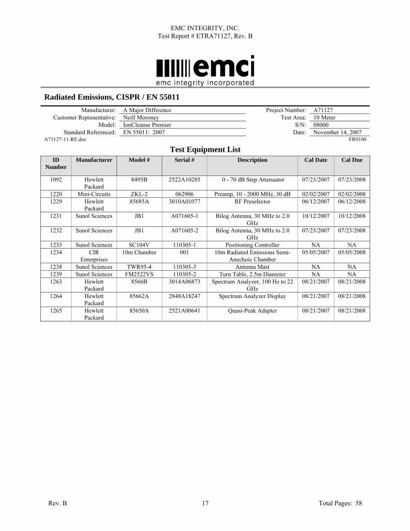
Test Equipment List ID
Number Manufacturer Model # Serial # Description Cal Date Cal Due
1092 Hewlett Packard
8495B 2522A10285 0 - 70 dB Step Attenuator 07/23/2007 07/23/2008
1220 Mini-Circuits ZKL-2 062906 Preamp, 10 - 2000 MHz, 30 dB 02/02/2007 02/02/2008 1229 Hewlett
Packard 85685A 3010A01077 RF Preselector 06/12/2007 06/12/2008
1231 Sunol Sciences JB1 A071605-1 Bilog Antenna, 30 MHz to 2.0 GHz
10/12/2007 10/12/2008
1232 Sunol Sciences JB1 A071605-2 Bilog Antenna, 30 MHz to 2.0 GHz
07/23/2007 07/23/2008
1233 Sunol Sciences SC104V 110305-1 Positioning Controller NA NA 1234 CIR
Enterprises 10m Chamber 001 10m Radiated Emissions Semi-
Anechoic Chamber 05/05/2007 05/05/2008
1238 Sunol Sciences TWR95-4 110305-3 Antenna Mast NA NA 1239 Sunol Sciences FM2522VS 110305-2 Turn Table, 2.5m Diameter NA NA 1263 Hewlett
Packard 8566B 3014A06873 Spectrum Analyzer, 100 Hz to 22
GHz 08/21/2007 08/21/2008
1264 Hewlett Packard
85662A 2848A18247 Spectrum Analyzer Display 08/21/2007 08/21/2008
1265 Hewlett Packard
85650A 2521A00641 Quasi-Peak Adapter 08/21/2007 08/21/2008
Rev. B Total Pages: 58 17

EMC INTEGRITY, INC. Test Report # ETRA71127, Rev. B
APPENDIX B
Conducted Emissions Test Data 115 Vac/60 Hz
Rev. B Total Pages: 58 18

EMC INTEGRITY, INC. Test Report # ETRA71127, Rev. B
Conducted Emissions, CISPR / EN 55011 Manufacturer: A Major Difference Project Number: A71127
Customer Representative: Neill Moroney Test Area: 10 Meter Model: IonCleanse Premier S/N: 08000
Standard Referenced: EN 55011: 2007 Date: November 14, 2007 Temperature: 20˚C Humidity: 25% Pressure: 844mb
Input Voltage: 115Vac/60Hz
Configuration of Unit: Normal Operation Mode #1
Test Engineer: Tom Wittig A71127-11-CE.doc FR0100 Type Frequency
(MHz) Level
(dBuV) Transducer
(dB) Gain / Loss
(dB) Final
(dBuV) Test Point Margin: FCC Class
B AV (dB) Margin: FCC
Class B QP (dB) AV 0.159 10.6 3.8 10.0 24.4 Line 1 31.38 - QP 0.159 23.7 3.8 10.0 37.5 Line 1 - 28.23 AV 0.269 18.8 2.1 10.0 30.8 Line 1 21.79 - QP 0.269 20.6 2.1 10.0 32.6 Line 1 - 29.98 AV 1.145 17.6 1.3 10.0 29.0 Line 1 17.01 - QP 1.145 19.7 1.3 10.0 31.1 Line 1 - 24.93 AV 1.888 18.9 1.6 10.0 30.4 Line 1 15.58 - QP 1.888 21.1 1.6 10.0 32.7 Line 1 - 23.31 AV 4.586 19.2 1.6 10.0 30.8 Line 1 15.24 - QP 4.586 22.5 1.6 10.0 34.1 Line 1 - 21.92 AV 9.650 26.4 1.4 10.0 37.8 Line 1 12.25 - QP 9.650 29.2 1.4 10.0 40.7 Line 1 - 19.35 AV 0.152 11.8 3.9 10.0 25.6 Neutral 30.32 - QP 0.152 27.0 3.9 10.0 40.9 Neutral - 25.04 AV 0.202 14.5 3.3 10.0 27.8 Neutral 26.67 - QP 0.202 21.2 3.3 10.0 34.5 Neutral - 29.97 AV 0.269 12.6 2.1 10.0 24.7 Neutral 27.93 - QP 0.269 16.4 2.1 10.0 28.5 Neutral - 34.13 AV 2.095 12.7 1.6 10.0 24.2 Neutral 21.76 - QP 2.095 16.5 1.6 10.0 28.1 Neutral - 27.92 AV 9.196 24.3 1.5 10.0 35.8 Neutral 14.16 - QP 9.196 27.7 1.5 10.0 39.3 Neutral - 20.75 AV 14.881 24.9 1.2 10.0 36.1 Neutral 13.85 - QP 14.881 28.4 1.2 10.0 39.6 Neutral - 20.39 The highest emission measured was at 14.881 MHz, which was 13.85 dB below the limit.
“Type” refers to the type of measurement performed. The type of measurement made is based on the requirements of the particular standard:
• PK = Peak Measurement
• QP = Quasi-Peak Measurement
• AV = Video Average Measurement
The “Final” emissions level is attained by taking the “Level” and adding the “Transducer” factor and the “Gain/Loss” factor.
The “TestPoint” indicates which AC or DC input power line or which I/O cable the measurement was made on.
The “Margin” is with reference to the emissions limit. A positive number indicates that the emission measurement is below the limit. A negative number indicates that the emission measurement exceeds the limit.
Rev. B Total Pages: 58 19

EMC INTEGRITY, INC. Test Report # ETRA71127, Rev. B
Conducted Emissions, CISPR / EN 55011 Manufacturer: A Major Difference Project Number: A71127
Customer Representative: Neill Moroney Test Area: 10 Meter Model: IonCleanse Premier S/N: 08000
Standard Referenced: EN 55011: 2007
Date: November 14, 2007 A71127-11-CE.doc FR0100
Figure B1: Conducted Emissions Prescan - Line 1.
Rev. B Total Pages: 58 20

EMC INTEGRITY, INC. Test Report # ETRA71127, Rev. B
Conducted Emissions, CISPR / EN 55011 Manufacturer: A Major Difference Project Number: A71127
Customer Representative: Neill Moroney Test Area: 10 Meter Model: IonCleanse Premier S/N: 08000
Standard Referenced: EN 55011: 2007
Date: November 14, 2007 A71127-11-CE.doc FR0100
Figure B2: Conducted Emissions Prescan - Neutral.
Rev. B Total Pages: 58 21

EMC INTEGRITY, INC. Test Report # ETRA71127, Rev. B
Conducted Emissions, CISPR / EN 55011 Manufacturer: A Major Difference Project Number: A71127
Customer Representative: Neill Moroney Test Area: 10 Meter Model: IonCleanse Premier S/N: 08000
Standard Referenced: EN 55011: 2007
Date: November 14, 2007 A71127-11-CE.doc FR0100
Figure B3: Conducted Emissions Test Setup - Front
Rev. B Total Pages: 58 22
EMC INTEGRITY, INC. Test Report # ETRA71127, Rev. B
Conducted Emissions, CISPR / EN 55011 Manufacturer: A Major Difference Project Number: A71127
Customer Representative: Neill Moroney Test Area: 10 Meter Model: IonCleanse Premier S/N: 08000
Standard Referenced: EN 55011: 2007
Date: November 14, 2007 A71127-11-CE.doc FR0100
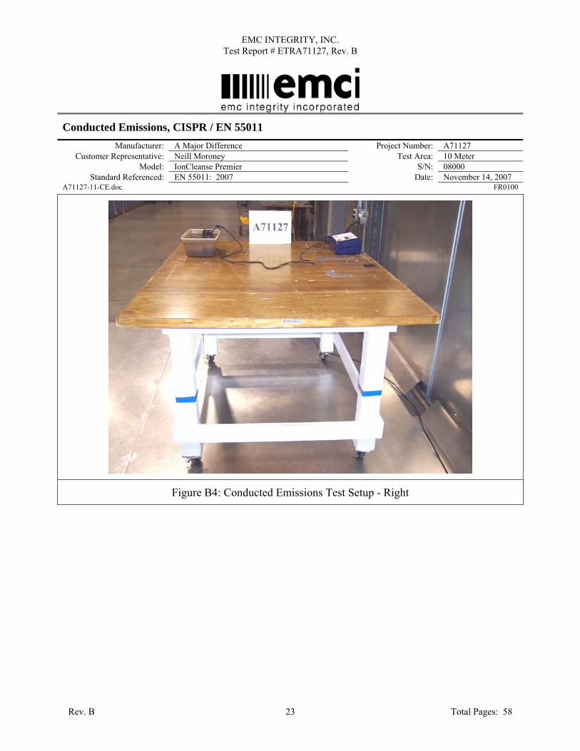
Figure B4: Conducted Emissions Test Setup - Right
Rev. B Total Pages: 58 23

EMC INTEGRITY, INC. Test Report # ETRA71127, Rev. B
Conducted Emissions, CISPR / EN 55011 Manufacturer: A Major Difference Project Number: A71127
Customer Representative: Neill Moroney Test Area: 10 Meter Model: IonCleanse Premier S/N: 08000
Standard Referenced: EN 55011: 2007
Date: November 14, 2007 A71127-11-CE.doc FR0100
Figure B5: Conducted Emissions Test Setup - Back
Rev. B Total Pages: 58 24

EMC INTEGRITY, INC. Test Report # ETRA71127, Rev. B
Conducted Emissions, CISPR / EN 55011 Manufacturer: A Major Difference Project Number: A71127
Customer Representative: Neill Moroney Test Area: 10 Meter Model: IonCleanse Premier S/N: 08000
Standard Referenced: EN 55011: 2007
Date: November 14, 2007 A71127-11-CE.doc FR0100
Figure B6: Conducted Emissions Test Setup - Left
Rev. B Total Pages: 58 25
EMC INTEGRITY, INC. Test Report # ETRA71127, Rev. B
Conducted Emissions, CISPR / EN 55011 Manufacturer: A Major Difference Project Number: A71127
Customer Representative: Neill Moroney Test Area: 10 Meter Model: IonCleanse Premier S/N: 08000
Standard Referenced: EN 55011: 2007
Date: November 14, 2007 A71127-11-CE.doc FR0100
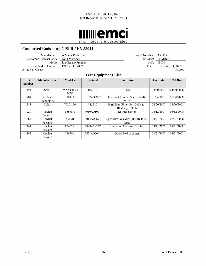
Test Equipment List ID
Number Manufacturer Model # Serial # Description Cal Date Cal Due
1194 Solar 9252-50-R-24-BNC
042012 LISN 04/20/2007 04/20/2008
1201 Agilent Technology
11947A 3107A03807 Transient Limiter, 9 kHz to 200 MHz
01/04/2007 01/04/2008
1213 Solar 7930-100 885210 High Pass Filter, fc: 100kHz, -100dB @ 33kHz
04/20/2007 06/20/2008
1229 Hewlett Packard
85685A 3010A01077 RF Preselector 06/12/2007 06/12/2008
1263 Hewlett Packard
8566B 3014A06873 Spectrum Analyzer, 100 Hz to 22 GHz
08/21/2007 08/21/2008
1264 Hewlett Packard
85662A 2848A18247 Spectrum Analyzer Display 08/21/2007 08/21/2008
1265 Hewlett Packard
85650A 2521A00641 Quasi-Peak Adapter 08/21/2007 08/21/2008
Rev. B Total Pages: 58 26

EMC INTEGRITY, INC. Test Report # ETRA71127, Rev. B
APPENDIX C
Conducted Emissions Test Data 230 Vac/50 Hz
Rev. B Total Pages: 58 27

EMC INTEGRITY, INC. Test Report # ETRA71127, Rev. B
Conducted Emissions, CISPR / EN 55011 Manufacturer: A Major Difference Project Number: A71127
Customer Representative: Neill Moroney Test Area: 10 Meter Model: IonCleanse Premier S/N: 08000
Standard Referenced: EN 55011: 2007 Date: November 14, 2007 Temperature: 20˚C Humidity: 25% Pressure: 844mb
Input Voltage: 230Vac/50Hz
Configuration of Unit: Normal Operation Mode #1
Test Engineer: Tom Wittig A71127-11-CE.doc FR0100 Type Frequency
(MHz) Level
(dBuV) Transducer
(dB) Gain / Loss
(dB) Final
(dBuV) Test Point Margin: EN55011
Class B Group 1 & 2 AV (dB)
Margin: EN55011 Class B Group 1 &
2 QP (dB) AV 0.199 25.1 3.4 10.0 38.6 Line 1 16.04 - QP 0.199 27.0 3.4 10.0 40.4 Line 1 - 24.17 AV 0.400 22.1 1.7 10.0 33.8 Line 1 15.06 - QP 0.400 22.7 1.7 10.0 34.4 Line 1 - 24.44 AV 0.468 21.9 1.6 10.0 33.5 Line 1 13.44 - QP 0.468 23.0 1.6 10.0 34.5 Line 1 - 22.36 AV 0.738 22.6 1.5 10.0 34.0 Line 1 11.95 - QP 0.738 23.6 1.5 10.0 35.1 Line 1 - 20.88 AV 1.876 24.8 1.6 10.0 36.3 Line 1 9.69 - QP 1.876 24.6 1.6 10.0 36.1 Line 1 - 19.88 AV 6.306 28.8 1.6 10.0 40.4 Line 1 9.60 - QP 6.306 31.5 1.6 10.0 43.1 Line 1 - 16.92 AV 0.202 19.4 3.4 10.0 32.7 Neutral 21.82 - QP 0.202 23.3 3.4 10.0 36.6 Neutral - 27.89 AV 0.336 14.3 1.9 10.0 26.2 Neutral 24.48 - QP 0.336 16.8 1.9 10.0 28.6 Neutral - 32.05 AV 0.404 16.5 1.7 10.0 28.2 Neutral 20.55 - QP 0.404 18.2 1.7 10.0 29.9 Neutral - 28.82 AV 1.349 16.2 1.4 10.0 27.7 Neutral 18.35 - QP 1.349 18.4 1.4 10.0 29.8 Neutral - 26.25 AV 6.209 25.1 1.6 10.0 36.8 Neutral 13.25 - QP 6.209 26.7 1.6 10.0 38.3 Neutral - 21.66 AV 8.440 22.1 1.6 10.0 33.7 Neutral 16.30 - QP 8.440 25.9 1.6 10.0 37.5 Neutral - 22.48 The highest emission measured was at 6.209 MHz, which was 13.25 dB below the limit.
“Type” refers to the type of measurement performed. The type of measurement made is based on the requirements of the particular standard:
• PK = Peak Measurement
• QP = Quasi-Peak Measurement
• AV = Video Average Measurement
The “Final” emissions level is attained by taking the “Level” and adding the “Transducer” factor and the “Gain/Loss” factor.
The “TestPoint” indicates which AC or DC input power line or which I/O cable the measurement was made on.
The “Margin” is with reference to the emissions limit. A positive number indicates that the emission measurement is below the limit. A negative number indicates that the emission measurement exceeds the limit.
Rev. B Total Pages: 58 28

EMC INTEGRITY, INC. Test Report # ETRA71127, Rev. B
Conducted Emissions, CISPR / EN 55011 Manufacturer: A Major Difference Project Number: A71127
Customer Representative: Neill Moroney Test Area: 10 Meter Model: IonCleanse Premier S/N: 08000
Standard Referenced: EN 55011: 2007
Date: November 14, 2007 A71127-11-CE.doc FR0100
Figure C1: Conducted Emissions Prescan - Line 1.
Rev. B Total Pages: 58 29
EMC INTEGRITY, INC. Test Report # ETRA71127, Rev. B
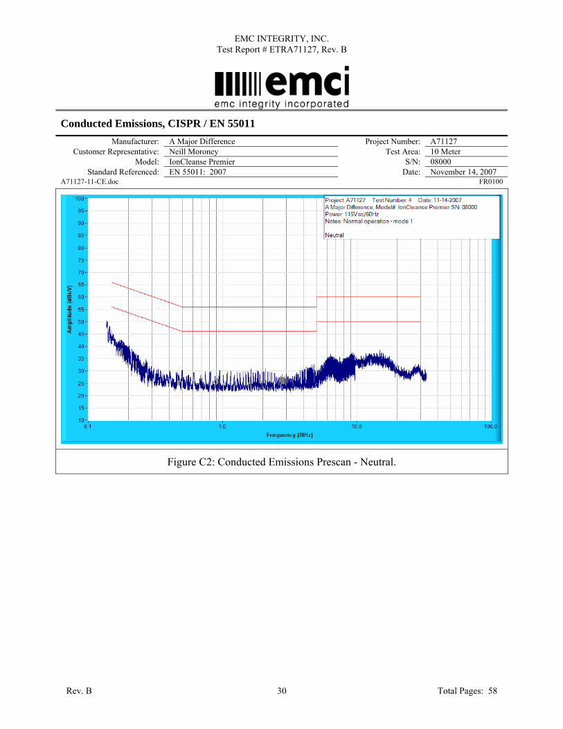
Conducted Emissions, CISPR / EN 55011 Manufacturer: A Major Difference Project Number: A71127
Customer Representative: Neill Moroney Test Area: 10 Meter Model: IonCleanse Premier S/N: 08000
Standard Referenced: EN 55011: 2007
Date: November 14, 2007 A71127-11-CE.doc FR0100
Figure C2: Conducted Emissions Prescan - Neutral.
Rev. B Total Pages: 58 30

EMC INTEGRITY, INC. Test Report # ETRA71127, Rev. B
Conducted Emissions, CISPR / EN 55011 Manufacturer: A Major Difference Project Number: A71127
Customer Representative: Neill Moroney Test Area: 10 Meter Model: IonCleanse Premier S/N: 08000
Standard Referenced: EN 55011: 2007
Date: November 14, 2007 A71127-11-CE.doc FR0100
Figure C3: Conducted Emissions Test Setup - Front
Rev. B Total Pages: 58 31

EMC INTEGRITY, INC. Test Report # ETRA71127, Rev. B
Conducted Emissions, CISPR / EN 55011 Manufacturer: A Major Difference Project Number: A71127
Customer Representative: Neill Moroney Test Area: 10 Meter Model: IonCleanse Premier S/N: 08000
Standard Referenced: EN 55011: 2007
Date: November 14, 2007 A71127-11-CE.doc FR0100
Figure C4: Conducted Emissions Test Setup - Right
Rev. B Total Pages: 58 32

EMC INTEGRITY, INC. Test Report # ETRA71127, Rev. B
Conducted Emissions, CISPR / EN 55011 Manufacturer: A Major Difference Project Number: A71127
Customer Representative: Neill Moroney Test Area: 10 Meter Model: IonCleanse Premier S/N: 08000
Standard Referenced: EN 55011: 2007
Date: November 14, 2007 A71127-11-CE.doc FR0100
Figure C5: Conducted Emissions Test Setup - Back
Rev. B Total Pages: 58 33
EMC INTEGRITY, INC. Test Report # ETRA71127, Rev. B
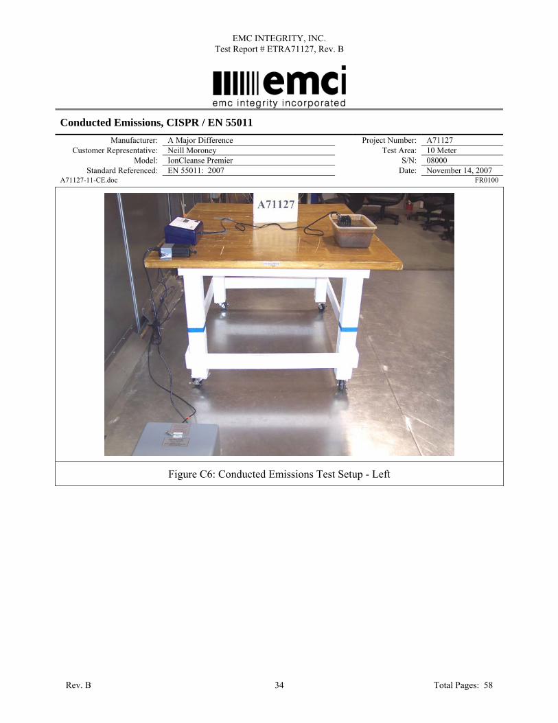
Conducted Emissions, CISPR / EN 55011 Manufacturer: A Major Difference Project Number: A71127
Customer Representative: Neill Moroney Test Area: 10 Meter Model: IonCleanse Premier S/N: 08000
Standard Referenced: EN 55011: 2007
Date: November 14, 2007 A71127-11-CE.doc FR0100
Figure C6: Conducted Emissions Test Setup - Left
Rev. B Total Pages: 58 34

EMC INTEGRITY, INC. Test Report # ETRA71127, Rev. B
Conducted Emissions, CISPR / EN 55011 Manufacturer: A Major Difference Project Number: A71127
Customer Representative: Neill Moroney Test Area: 10 Meter Model: IonCleanse Premier S/N: 08000
Standard Referenced: EN 55011: 2007
Date: November 14, 2007 A71127-11-CE.doc FR0100
Test Equipment List ID
Number Manufacturer Model # Serial # Description Cal Date Cal Due
1194 Solar 9252-50-R-24-BNC
042012 LISN 04/20/2007 04/20/2008
1201 Agilent Technology
11947A 3107A03807 Transient Limiter, 9 kHz to 200 MHz
01/04/2007 01/04/2008
1213 Solar 7930-100 885210 High Pass Filter, fc: 100kHz, -100dB @ 33kHz
04/20/2007 06/20/2008
1229 Hewlett Packard
85685A 3010A01077 RF Preselector 06/12/2007 06/12/2008
1263 Hewlett Packard
8566B 3014A06873 Spectrum Analyzer, 100 Hz to 22 GHz
08/21/2007 08/21/2008
1264 Hewlett Packard
85662A 2848A18247 Spectrum Analyzer Display 08/21/2007 08/21/2008
1265 Hewlett Packard
85650A 2521A00641 Quasi-Peak Adapter 08/21/2007 08/21/2008
Rev. B Total Pages: 58 35

EMC INTEGRITY, INC. Test Report # ETRA71127, Rev. B
APPENDIX D
AC Power Line Flicker Test Data
Rev. B Total Pages: 58 36

EMC INTEGRITY, INC. Test Report # ETRA71127, Rev. B
AC Power-Line Flicker per IEC / EN 61000-3-3 Manufacturer: A Major Difference Project Number: A71127
Customer Representative: Neill Moroney Test Area: GP 2 Model: IonCleanse Premier S/N: 08000
Standard Referenced: EN 61000 -6-1 : 2007 Date: November 29, 2007 Temperature: 21˚C Humidity: 32% Pressure: 834 mb
Input Voltage: 230VAC/50Hz
Configuration of Unit: Normal Operation Mode #1
Test Engineer: Tom Wittig A71127-3-3.doc FR0100
Flicker Test Summary per EN/IEC61000-3-3 (Run time)
EUT: IonCleanse Premier Tested by: Tom Wittig Test category: All parameters (European limits) Test Margin: 100 Test date: 11/29/2007 Start time: 3:29:51 PM End time: 5:30:17 PM Test duration (min): 120 Data file name: F-000022.cts_data Comment: A71127 Customer: A Major Difference Test Result: Pass Status: Test Completed Psti and limit line European Limits
0.25
0.50
0.75
1.00
Pst
15:40:1915:50:2116:00:2116:10:2216:20:2216:30:1916:40:1816:50:1717:00:1717:10:1717:20:1717:30:16
Rev. B Total Pages: 58 37

EMC INTEGRITY, INC. Test Report # ETRA71127, Rev. B
Plt and limit line
0.20.30.40.50.6
P
lt
17:30:16
Parameter values recorded during the test: Vrms at the end of test (Volt): 230.27 Highest dt (%): 0.00 Test limit (%): 3.30 Pass Time(mS) > dt: 0.0 Test limit (mS): 500.0 Pass Highest dc (%): 0.00 Test limit (%): 3.30 Pass Highest dmax (%): 0.00 Test limit (%): 4.00 Pass Highest Pst (10 min. period): 0.160 Test limit: 1.000 Pass Highest Plt (2 hr. period): 0.160 Test limit: 0.650 Pass
Rev. B Total Pages: 58 38

EMC INTEGRITY, INC. Test Report # ETRA71127, Rev. B
AC Power-Line Flicker per IEC / EN 61000-3-3 Manufacturer: A Major Difference Project Number: A71127
Customer Representative: Neill Moroney Test Area: GP 2 Model: IonCleanse Premier S/N: 08000
Standard Referenced: EN 61000 -6-1 : 2007
Date: November 29, 2007 A71127-3-3.doc FR0100
Figure D1. AC Power Line Flicker Test Setup.
Rev. B Total Pages: 58 39
EMC INTEGRITY, INC. Test Report # ETRA71127, Rev. B
AC Power-Line Flicker per IEC / EN 61000-3-3 Manufacturer: A Major Difference Project Number: A71127
Customer Representative: Neill Moroney Test Area: GP 2 Model: IonCleanse Premier S/N: 08000
Standard Referenced: EN 61000 -6-1 : 2007
Date: November 29, 2007 A71127-3-3.doc FR0100
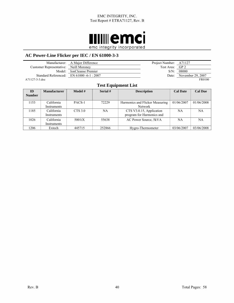
Test Equipment List ID
Number Manufacturer Model # Serial # Description Cal Date Cal Due
1153 California Instruments
PACS-1 72229 Harmonics and Flicker Measuring Network
01/06/2007 01/06/2008
1185 California Instruments
CTS 3.0 NA CTS V3.0.15, Application program for Harmonics and
NA NA
1026 California Instruments
5001iX 55638 AC Power Source, 5kVA NA NA
1206 Extech 445715 252866 Hygro-Thermometer 03/06/2007 03/06/2008
Rev. B Total Pages: 58 40

EMC INTEGRITY, INC. Test Report # ETRA71127, Rev. B
APPENDIX E
Product Data Sheet
Rev. B Total Pages: 58 41

EMC INTEGRITY, INC. Test Report # ETRA71127, Rev. B
1.0 Client Information Client Information Manufacturer Name A Major Difference Address 10235 S. Progress Way, Units 7 & 8 City Parker State Colorado Zip Code 80134 Client Representative Neill Moroney Title Phone 303-840-8206 Fax 303-840-8320 Email [email protected]
2.0 Product Information - General
Product Information Product Name (as it should appear on test report) IonCleanse Premier Model Number IonCleanse Premier Functional description of product
Vitality Enhancement System
Product type (IT, Medical, Scientific, Industrial, etc.) Household Is the product an intentional radiator No Product Dimensions 12 x 8 x 4 Product Weight < 10 lbs Will fork lift be required No Applicable Standards, if known Generic (61000-6-1 / EN55011Grp 1 Class A) Describe all environment(s) where product will be used
Household/non medical practitioners
Does product consist of multiple components? (If yes, please describe each system component)
Yes – Power Supply (external), Main Box and Array
Cycle time > 3 seconds? (If yes, How long?) No Highest internally generated frequency 4 MHz Product Set-up Time < 15 minutes Boot up time in the event of an unintentional power down
< 5 minutes
Identify all I/O Connections as well as maximum associated cable lengths below Model No. Description Shielded? Length Quantity
Array Cable 2 ft (approx) 1
Rev. B Total Pages: 58 42

EMC INTEGRITY, INC. Test Report # ETRA71127, Rev. B
3.0 Power Power Requirements Input Voltage Rating as it appears on unit, power supply, or power brick
External Brick (SinPro model MPU50-107) 100-240 Vac, 47-63 Hz
Input Current (specify @ 230 Vac/50 Hz) 1.35 A Single or Multi-Phase (If multi-phase, specify delta or wye)
Single Phase
Is input power connector two-prong (Hot & Neutral) or 3-prong (H, N, Ground)
3 Prong grounded
Does UUT have more than 1 power cord? (If yes, explain.)
No
4.0 Unit Under Test (UUT) – Detailed Information UUT Hardware Condition New – Production Line Configuration During Test Mode 1 for 60 minutes, with salinity level set to approx. 2.0 Amps
Input Power 230 Vac UUT Components
Name Model No. Serial No. Description P/S MPU50-107 --- External Sinpro AC/DC Converter.
Main Box IonCleanse Premier 08000 Main control box for IonCleanse Premier
Array --- --- Array to be immersed in water solution
I/O Cabling See Section 2.0 for details UUT Software/Firmware
Name Version/Revision Functionality
-- 5A05 Custom software to control parameters (Time, sample rate, etc) of product
UUT Operating Conditions List all frequencies the product generates/uses 4 MHz
How will product be exercised during test? Mode 1 How will product be monitored during test? Display
What are the product’s critical parameters? No change in display Specify tolerance of all critical parameters. No Tolerance
Rev. B Total Pages: 58 43

EMC INTEGRITY, INC. Test Report # ETRA71127, Rev. B
5.0 Support Equipment (SE) – Detailed Information Support Equipment (SE)
Name Model No. Serial No. Description N/A N/A N/A N/A
SE I/O Cabling Model No. Description Shielded? Length Quantity
N/A N/A N/A N/A N/A
SE Software/Firmware Name Version/Revision Functionality N/A N/A N/A
6.0 Block Diagram
Rev. B
100-240 Vac
External AC P/S(MPU50-107)
Key
c
(Must be compl
20 Vd
Control Box Board Display
Array
eted prior to testing).
Total Pages: 58 44

EMC INTEGRITY, INC. Test Report # ETRA71127, Rev. B
APPENDIX F
EMI Test Log
Rev. B Total Pages: 58 45

EMC INTEGRITY, INC. Test Report # ETRA71127, Rev. B
EMI Test Log Manufacturer: A Major Difference Project Number: A71127
Model: IonCleanse S/N: 08000 Customer Representative: Neill Moroney
Standard Referenced: EN61000-6-1 & EN55011/FCC Part 15
FR0105
Test Test Code
Date Event Time (hrs)
Result Initials
RE 1152 November 14, 2007
Test #1, 30-1000 MHz, 8 rads, 4 heights, 3 second dwell Normal operation – mode 3
Mode 3, saw spermatic broadband noise spikes occurred due to units relay switching from negative to positive modes
Test #2, 30-1000 MHz, 8 rads, 4 heights, 3 second dwell Normal operation – mode 1
2.0 Pass TW
CE 2151 Test#3: 150kHz – 30MHz, 230VAC/50Hz 1.0 Pass KJ 2341 Test#4: 150kHz – 30MHz, 115VAC/50Hz 1.0 Pass KJ
4-3 5008 November 21, 2007
Performed RI from 80-1000MHz @ 3V/m (230VAC/50Hz) 8.0 -- BN
Front Side V-Pole At 465MHz EUT operational state changes to High Temp Overheat State, EUT requires reboot.
Disconnected the Array and retested on Front Side V-pole at 465MHz and EUT still goes into an error.
Modification required for compliance – Original software (Revision 5A04) was designed to set alarm state for 1 single instance of temperature reading above 180°F. Product modified to incorporate software Revision 5A05 to require product to maintain temperature reading above 180°F for 150 consecutive seconds before proceeding to alarm state.
Performed RI from 80-1000MHz @ 3V/m (230VAC/50Hz) On Front Side and Right Side at about 85-88MHz EUT resets itself. On Right Side H-Pole EUT is being retuned at 86MHz from + to - With the keypad ribbon cable disconnected EUT does not have any
errors.
Modification required for compliance: Added a Ferrite to the keypad ribbon cable and Ran EUT up to 100MHz and it passed up to that point. H-Pole Right Side.
Removed ferrite and reran Right Side H-pole at 85 MHz EUT resets itself. (X2)
Put ferrite back on keypad ribbon cable reran Right Side H-pole, ran up to 100MHz and EUT did not have an errors.
Completed RI on the Right Side H-pole. 4-6 4612 November 26,
2007 Performed CI @ 3Vrms (230VAC/50Hz). 2.0 Pass BN
4-4 4401 Performed EFT (230VAC/50Hz). 1.0 Pass BN 4-11 4101 Performed PQF (230VAC/50/60Hz). 1.0 Pass BN 4-11 4190 Performed PQF (230VAC/50/60Hz). 0.0 Pass BN
At 0% at 250 Cycles 50Hz and 0% at 300 Cycles 60Hz: EUT had to be restarted after every test.
4-5 4515 Performed Surge (230VAC/50Hz) 5.0 Pass BN 4-2 4223 Performed ESD (230VAC/50Hz) 3.0 Pass BN
Figure A3, Figure A4, Figure A5, Figure A6 and Figure A7: No Air Discharges
Rev. B Total Pages: 58 46

EMC INTEGRITY, INC. Test Report # ETRA71127, Rev. B
EMI Test Log Manufacturer: A Major Difference Project Number: A71127
Model: IonCleanse S/N: 08000 Customer Representative: Neill Moroney
Standard Referenced: EN61000-6-1 & EN55011/FCC Part 15
FR0105
Test Test Code
Date Event Time (hrs)
Result Initials
Figure A3: Figure A4 and Figure A5: No Contact Discharges. Figure A6 and Figure A7: Contact Discharges at +/-4kV Only.
4-3 4344 November 29, 2007
Performed RF Immunity, 80-1000 MHz 4.0 Pass TW
4-3 4391 Performed RF Immunity, 1400-2000 MHz 1.0 Pass TW 4-3 4391 Performed RF Immunity, 2000-2700 MHz 1.0 Pass TW 3-2 3302 Performed Flicker 2.0 Pass TW
Rev. B Total Pages: 58 47
EMC INTEGRITY, INC. Test Report # ETRA71127, Rev. B
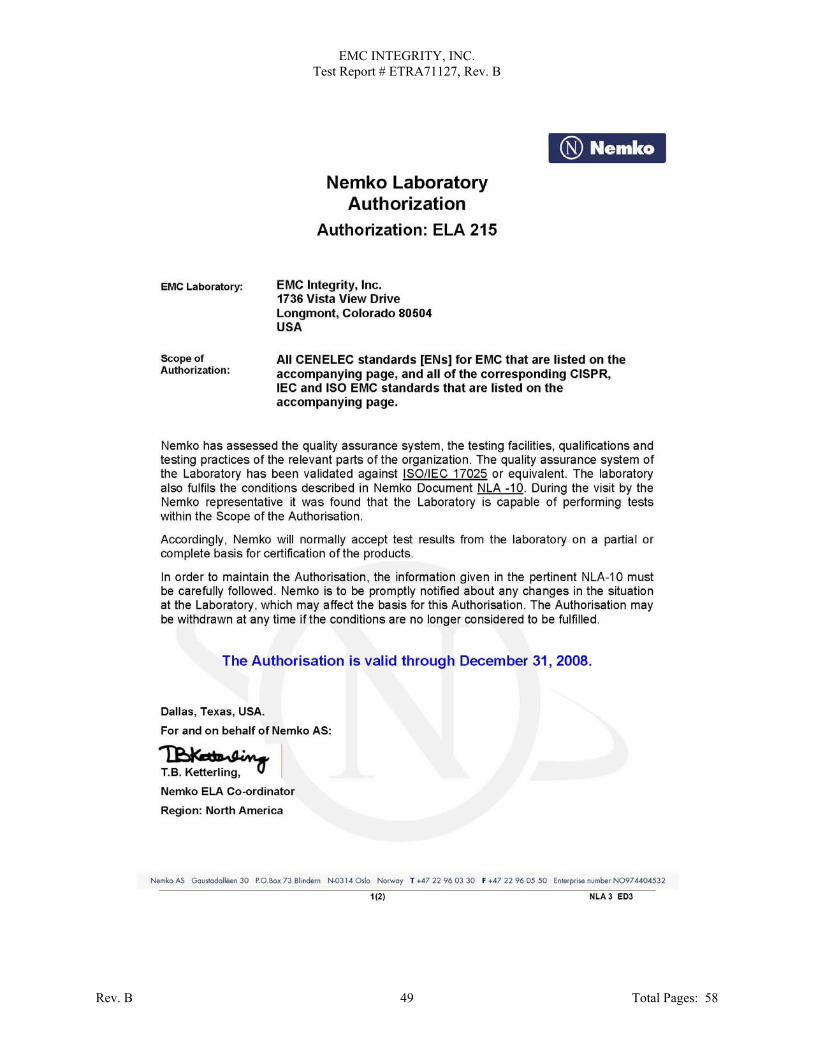
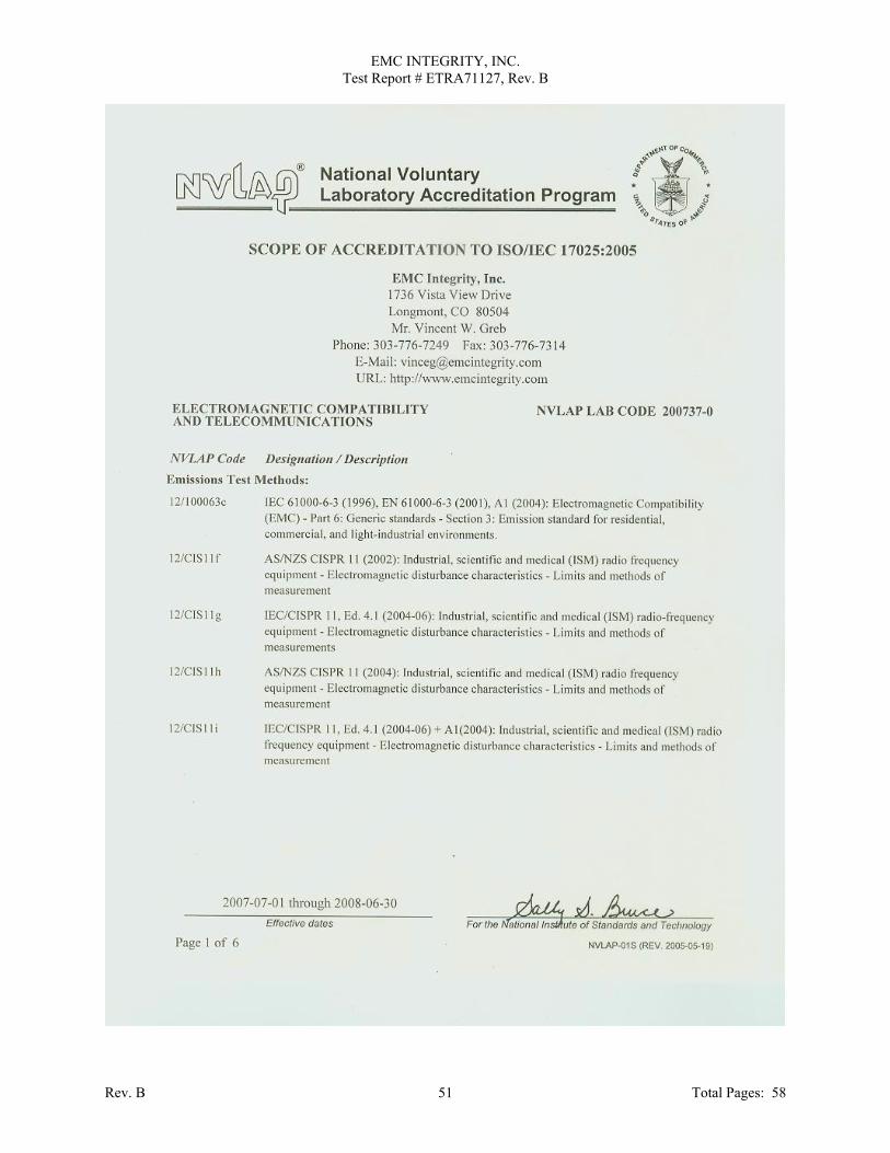
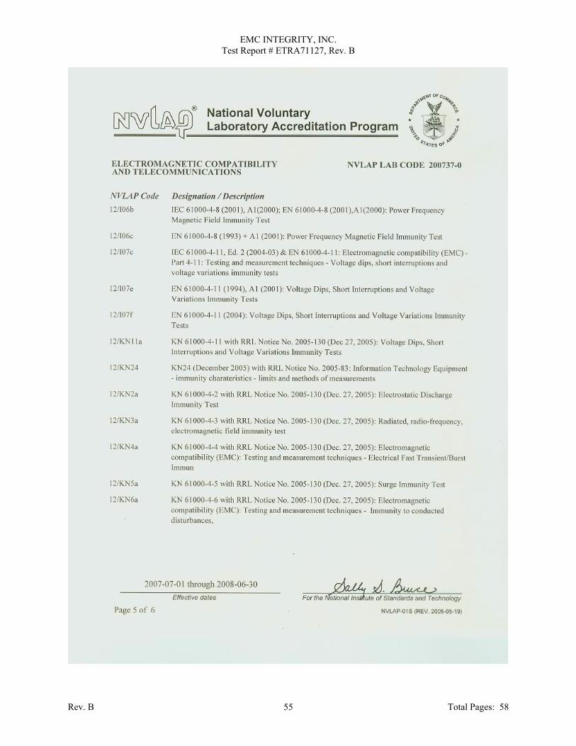
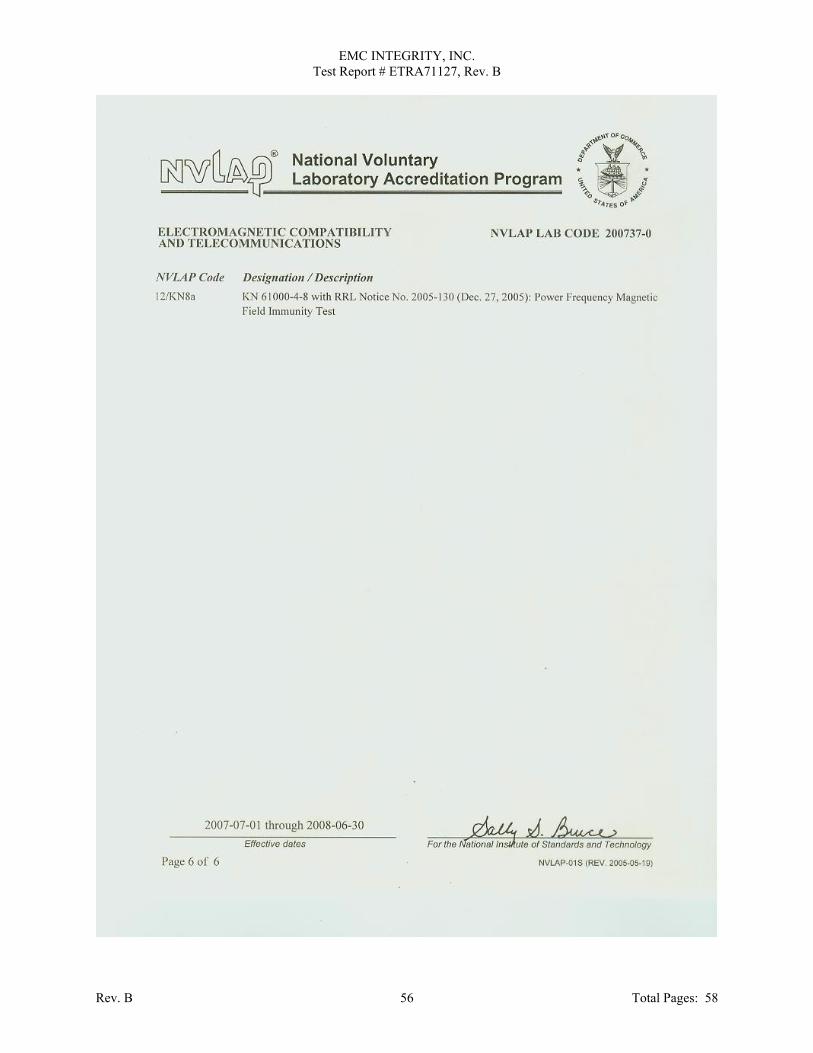
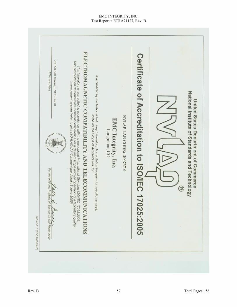
APPENDIX G
Laboratory Accreditations
Rev. B Total Pages: 58 48
EMC INTEGRITY, INC. Test Report # ETRA71127, Rev. B
Rev. B Total Pages: 58 49

EMC INTEGRITY, INC. Test Report # ETRA71127, Rev. B
Rev. B Total Pages: 58 50
EMC INTEGRITY, INC. Test Report # ETRA71127, Rev. B
Rev. B Total Pages: 58 51

EMC INTEGRITY, INC. Test Report # ETRA71127, Rev. B
Rev. B Total Pages: 58 52

EMC INTEGRITY, INC. Test Report # ETRA71127, Rev. B
Rev. B Total Pages: 58 53

EMC INTEGRITY, INC. Test Report # ETRA71127, Rev. B
Rev. B Total Pages: 58 54
EMC INTEGRITY, INC. Test Report # ETRA71127, Rev. B
Rev. B Total Pages: 58 55
EMC INTEGRITY, INC. Test Report # ETRA71127, Rev. B
Rev. B Total Pages: 58 56
EMC INTEGRITY, INC. Test Report # ETRA71127, Rev. B
Rev. B Total Pages: 58 57

EMC INTEGRITY, INC. Test Report # ETRA71127, Rev. B
END OF REPORT
Rev. B Total Pages: 58 58