test report form 200251231
TRANSCRIPT

EN 50014 - EN 50019
Page 2 of 47
Order No. 200251231
General remarks:
Description of equipment under test:
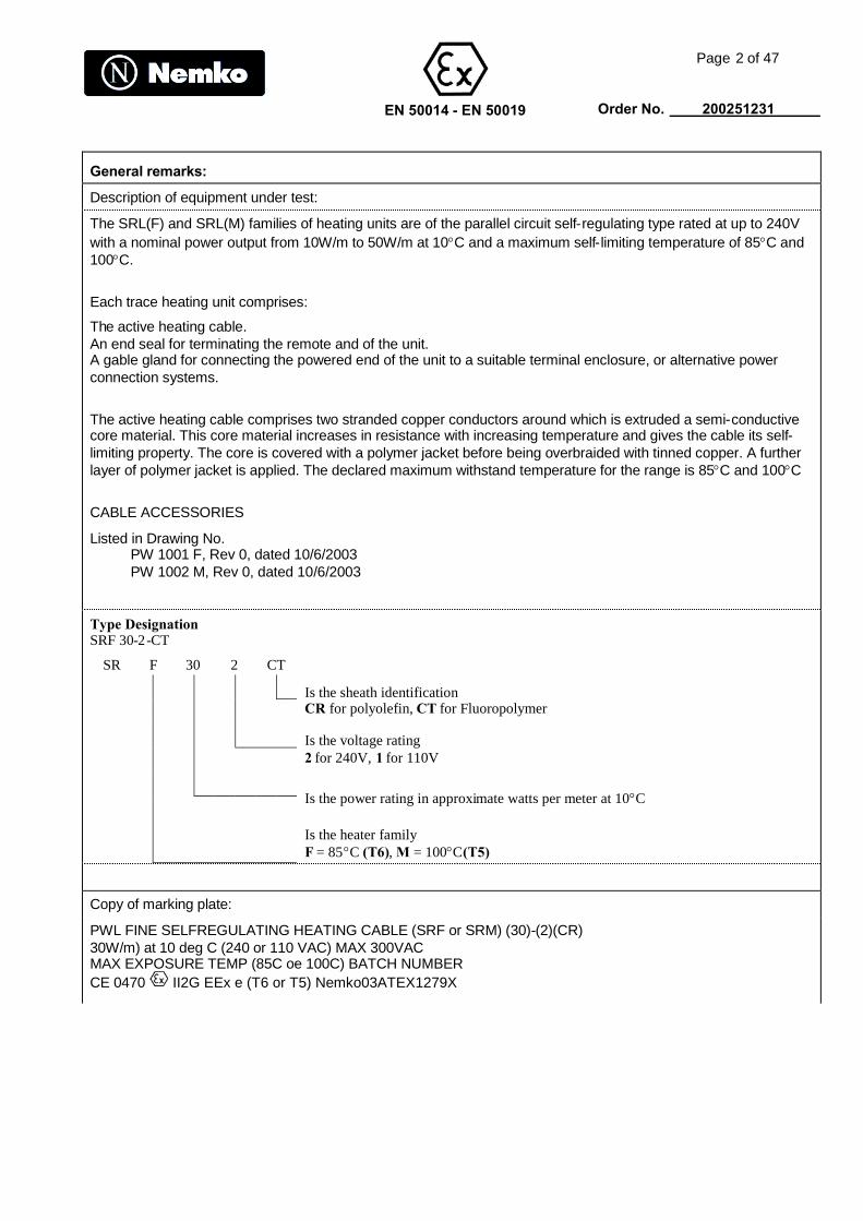
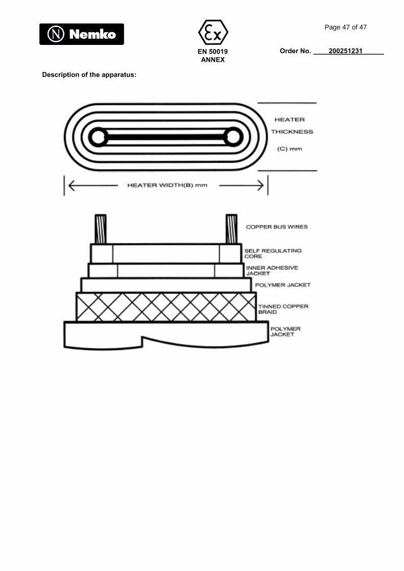
The SRL(F) and SRL(M) families of heating units are of the parallel circuit self-regulating type rated at up to 240Vwith a nominal power output from 10W/m to 50W/m at 10C and a maximum self-limiting temperature of 85C and100C.
Each trace heating unit comprises:
The active heating cable.An end seal for terminating the remote and of the unit.A gable gland for connecting the powered end of the unit to a suitable terminal enclosure, or alternative powerconnection systems.
The active heating cable comprises two stranded copper conductors around which is extruded a semi-conductivecore material. This core material increases in resistance with increasing temperature and gives the cable its self-limiting property. The core is covered with a polymer jacket before being overbraided with tinned copper. A furtherlayer of polymer jacket is applied. The declared maximum withstand temperature for the range is 85C and 100C
CABLE ACCESSORIES
Listed in Drawing No.PW 1001 F, Rev 0, dated 10/6/2003PW 1002 M, Rev 0, dated 10/6/2003
Type DesignationSRF 30-2-CT
SR F 30 2 CT
Is the sheath identificationCR for polyolefin, CT for Fluoropolymer
Is the voltage rating2 for 240V, 1 for 110V
Is the power rating in approximate watts per meter at 10C
Is the heater familyF = 85C (T6), M = 100C(T5)
Copy of marking plate:
PWL FINE SELFREGULATING HEATING CABLE (SRF or SRM) (30)-(2)(CR)30W/m) at 10 deg C (240 or 110 VAC) MAX 300VACMAX EXPOSURE TEMP (85C oe 100C) BATCH NUMBERCE 0470 II2G EEx e (T6 or T5) Nemko03ATEX1279X

EN 50014 - EN 50019
Page 3 of 47
Order No. 200251231
General remarks:
Throughout this report a comma is used as the decimal separator.
Possible test case verdicts:P = Pass, F = Fail, N = Not applicable. Placed in the column to the right (Verdict)
Tested according to additional information:
National requirements:
Other requirements:
Additional information:Calibration: All instruments used in the tests given in this test report are calibrated and
traceable to national or international standards.Further information about traceability will be given on request.
Measurement Measurement uncertainties are calculated for all instruments and instrumentuncertainty: set-ups given in this report. Calculations are based on the principles given in
the standard EA-4/02 (Dec. 1999).Further information about measurement uncertainties will be given on request
Evaluation of If not explicitly stated otherwise in the standard, the test is passed if theresults: measurement value is equal to or below the limit line, regardless of the
uncertainty of the measurement. If the measurement value is above the limit line, the test isnot passed - ref. IECEE/CTL (Sec) 056/94 (CLT = Committee of Testing Laboratories).The instrumentation accuracy is within limits agreed by this committee (ref. Nemko proc. P227).
Name and address of additional production-sites (factories):
Information about other standards / documents considered:
Tested according to national requirements for the following countries:
List of appendixes / enclosures to the test report:

EN 50014
Page 4 of 47
Order No. 200251231
Clause Requirement - Test Result - Remark Verdict
1 SCOPE The equipment is covered by thisstandard.
2 PUBLICATIONS This clause contains no requirements
3 DEFINITIONS AND SYMBOLS This clause contains no requirements
REQUIREMENTS FOR ALL ELECTRICALAPPARATUS
4 APPARATUS GROUPING ANDTEMPERATURE CLASSIFICATION
4.1 Electrical apparatus for potentially explosiveatmospheres is divided into:
Group I Electrical apparatus for minessusceptible to fire damp
N
Group II Electrical apparatus for placeswith a potentially atmosphere,other than mines susceptible tofire damp
P
4.2 Electrical apparatus of Group II may besubdivided according to the nature of thepotentially explosive atmosphere for which it isintended.
4.2.1 Types of protection flameproof enclosure “d”,and intrinsic safety “i”, subdivision of electricalapparatus of Group II
EEx e II N
4.2.2 For all types of protection, apparatus of GroupII shall be marked as a function of its maximumsurface temperature according to 5.1.2
P
4.3 The electrical apparatus may be tested for aparticular explosive atmosphere. In this case itshall be certified and marked accordingly
N
5 TEMPERATURES
5.1 Maximum surface temperature
5.1.1 For electrical apparatus of Group I themaximum surface temperature shall bespecified in relevant documentation(23.2):
N
This temperature shall not exceed:
150C on any surface where coal dust canform a layer
N
450C where coal dust is not expected toform a layer, provided that:
N
a) the actual maximum surface temperatureis marked on the apparatus, or
N
b) the symbol “X” is placed after thecertificate reference to indicate theconditions for safe use
N
5.1.2 Group II electrical apparatus shall be arrangedand marked (27.2 (f)) and shall either
EN 50014
Page 5 of 47
Order No. 200251231
Clause Requirement - Test Result - Remark Verdict
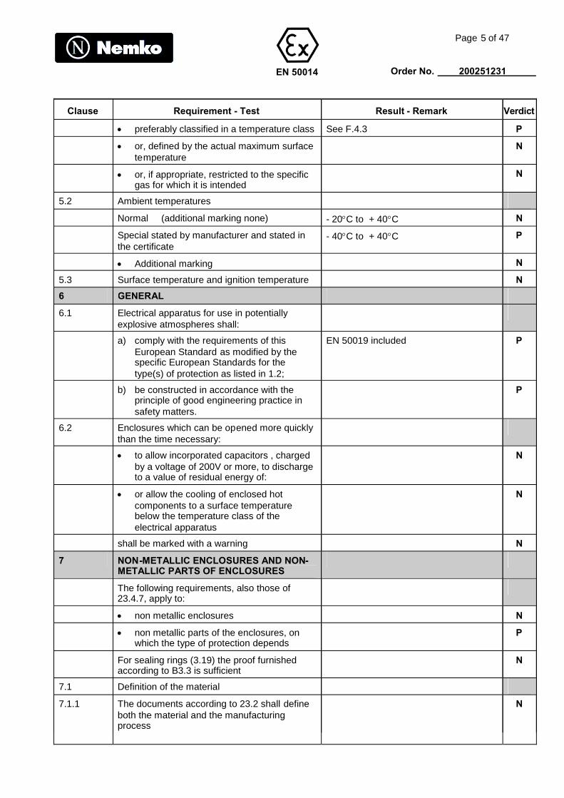
preferably classified in a temperature class See F.4.3 P
or, defined by the actual maximum surfacetemperature
N
or, if appropriate, restricted to the specificgas for which it is intended
N
5.2 Ambient temperatures
Normal (additional marking none) - 20C to + 40C N
Special stated by manufacturer and stated inthe certificate
- 40C to + 40C P
Additional marking N
5.3 Surface temperature and ignition temperature N
6 GENERAL
6.1 Electrical apparatus for use in potentiallyexplosive atmospheres shall:
a) comply with the requirements of thisEuropean Standard as modified by thespecific European Standards for thetype(s) of protection as listed in 1.2;
EN 50019 included P
b) be constructed in accordance with theprinciple of good engineering practice insafety matters.
P
6.2 Enclosures which can be opened more quicklythan the time necessary:
to allow incorporated capacitors , chargedby a voltage of 200V or more, to dischargeto a value of residual energy of:
N
or allow the cooling of enclosed hotcomponents to a surface temperaturebelow the temperature class of theelectrical apparatus
N
shall be marked with a warning N
7 NON-METALLIC ENCLOSURES AND NON-METALLIC PARTS OF ENCLOSURES
The following requirements, also those of23.4.7, apply to:
non metallic enclosures N
non metallic parts of the enclosures, onwhich the type of protection depends
P
For sealing rings (3.19) the proof furnishedaccording to B3.3 is sufficient
N
7.1 Definition of the material
7.1.1 The documents according to 23.2 shall defineboth the material and the manufacturingprocess
N

EN 50014
Page 6 of 47
Order No. 200251231
Clause Requirement - Test Result - Remark Verdict
7.1.2 For plastic materials , the definition shallinclude:
the name of the manufacturer Raychem P
the exact and complete reference of thematerial, its colour, as well as the kind andpercentage of fillers and other additiveswhen they are included
N
the possible surface treatments N
the temperature index “TI” N
7.1.3 It is not required to verify compliance of thematerial with its definition
N
7.2 Thermal endurance
TI at least 20K greater than the hottest point ofthe enclosure or part of the enclosure
Max. ambient = C N
The endurance to heat and cold satisfactory(see 23.4.7.3 and 23.4.7.4)
2 weeks in 95C 95% rel.hum2 weeks in 130
P
7.3 Electrostatic charges of enclosures or parts ofenclosures of plastic materials.
Applies only for:
non-fixed electrical apparatus N
fixed apparatus with plastic parts that arelikely to be rubbed or cleaned on site
N
7.3.1 Electrical apparatus of group I
Enclosures of plastic material with surfacearea projected in any direction of more than100cm2,shall be so designed that undernormal conditions of use, maintenance andcleaning, danger of ignition due to electrostaticcharges is avoided.
N
This requirement shall be satisfied by suitableselection of the material so that the insulationresistance of the enclosure, measured inaccordance with 23.4.7.8, does not exceed1Gor
N
by virtue of the size, shape and lay-out, orother protective methods, shall be such thatdangerous electrostatic charges are not likelyto occur.
N
If, however, the danger of ignition cannot beavoided in the design of the apparatus awarning label shall indicate the safetymeasures to be applied in service.
N
7.3.2 Electrical apparatus of group II
EN 50014
Page 7 of 47
Order No. 200251231
Clause Requirement - Test Result - Remark Verdict
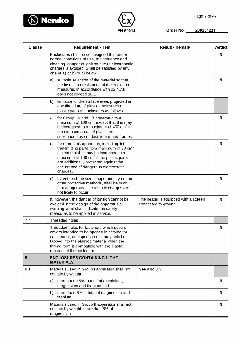
Enclosures shall be so designed that undernormal conditions of use, maintenance andcleaning, danger of ignition due to electrostaticcharges is avoided. Shall be satisfied by anyone of a) or b) or c) below.
N
a) suitable selection of the material so thatthe insulation resistance of the enclosure,measured in accordance with 23.4.7.8,does not exceed 1G
N
b) limitation of the surface area, projected inany direction, of plastic enclosures orplastic parts of enclosures as follows
for Group IIA and IIB apparatus to amaximum of 100 cm2 except that this maybe increased to a maximum of 400 cm2 ifthe exposed areas of plastic aresurrounded by conductive earthed frames
N
for Group IIC apparatus, including lighttransmitting parts, to a maximum of 20 cm2
except that this may be increased to amaximum of 100 cm2 if the plastic partsare additionally protected against theoccurrence of dangerous electrostaticcharges.
N
c) by virtue of the size, shape and lay-out, orother protective methods, shall be suchthat dangerous electrostatic charges arenot likely to occur.
N
If, however, the danger of ignition cannot beavoided in the design of the apparatus awarning label shall indicate the safetymeasures to be applied in service.
The heater is equipped with a screenconnected to ground
N
7.4 Threaded holes
Threaded holes for fasteners which securecovers intended to be opened in service foradjustment, or inspection etc. may only betapped into the plastics material when thethread form is compatible with the plasticmaterial of the enclosure
N
8 ENCLOSURES CONTAINING LIGHTMATERIALS
8.1 Materials used in Group I apparatus shall notcontain by weight
See also 8.3
a) more than 15% in total of aluminium,magnesium and titanium and
N
b) more than 6% in total of magnesium andtitanium
N
Materials used in Group II apparatus shall notcontain by weight: more than 6% ofmagnesium
N

EN 50014
Page 8 of 47
Order No. 200251231
Clause Requirement - Test Result - Remark Verdict
8.2 Threaded holes for fasteners which securecovers intended to be opened in service foradjustment, or inspection etc. may only betapped into the material when the thread formis compatible with the material used for theenclosure
N
The provisions of 8.1 do not apply to Group Isurveying instruments carried by persons.
N
9 FASTENERS
9.1 General
Parts used to prevent access to uninsulatedlive parts, released or removed only with theaid of a tool.
N
Fastening screws for enclosures of materialscontaining light metals may be made of lightmetal or plastics if the material of the fasteneris compatible with that of the enclosure
N
9.2 Special fasteners
the thread shall be coarse pitch inaccordance with ISO 262, with a tolerancefit of 6g/6H in accordance with ISO 965
N
the head of the screw or nut shall be inaccordance with ISO 4014, ISO 4017, ISO4032 or ISO 4762, and in case of hexagonsocket set screws ISO 4026, ISO 4027,ISO 4028 or ISO 4029.
N
the holes of the electrical apparatus shallcomply with the requirements of 9.3
N
9.3 Electrical apparatus - Holes for specialfasteners
9.3.1 Height of thread N
9.3.2 The thread shall have a tolerance of fit of 6H inaccordance with ISO 965, and either:
N
a) the hole under the head of the associatedfastener shall allow a clearance notgreater than a medium tolerance fit of H13in accordance with ISO 286-2 (see figure 1and ISO 273); or
N
b) the hole under the head (or nut) of anassociated reduced shank fastener shallbe threaded to enable the fastener to beretained. The dimensions of the threadedhole shall be such that the surroundingsurface in contact with the head of such afastener shall be at least equal to that of afastener with reduced shank in a clearancehole
N
EN 50014
Page 9 of 47
Order No. 200251231
Clause Requirement - Test Result - Remark Verdict
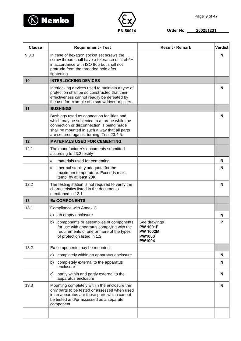
9.3.3 In case of hexagon socket set screws thescrew thread shall have a tolerance of fit of 6Hin accordance with ISO 965 but shall notprotrude from the threaded hole aftertightening
N
10 INTERLOCKING DEVICES
Interlocking devices used to maintain a type ofprotection shall be so constructed that theireffectiveness cannot readily be defeated bythe use for example of a screwdriver or pliers.
N
11 BUSHINGS
Bushings used as connection facilities andwhich may be subjected to a torque while theconnection or disconnection is being madeshall be mounted in such a way that all partsare secured against turning. Test 23.4.5.
N
12 MATERIALS USED FOR CEMENTING
12.1 The manufacturer’s documents submittedaccording to 23.2 testify
materials used for cementing N
thermal stability adequate for themaximum temperature. Exceeds max.temp. by at least 20K
N
12.2 The testing station is not required to verify thecharacteristics listed in the documentsmentioned in 12.1
N
13 Ex COMPONENTS
13.1 Compliance with Annex C
a) an empty enclosure N
b) components or assemblies of componentsfor use with apparatus complying with therequirements of one or more of the typesof protection listed in 1.2
See drawingsPW 1001FPW 1002MPW1003PW1004
P
13.2 Ex-components may be mounted:
a) completely within an apparatus enclosure N
b) completely external to the apparatusenclosure
N
c) partly within and partly external to theapparatus enclosure
N
13.3 Mounting completely within the enclosure theonly parts to be tested or assessed when usedin an apparatus are those parts which cannotbe tested and/or assessed as a separatecomponent
N
EN 50014
Page 10 of 47
Order No. 200251231
Clause Requirement - Test Result - Remark Verdict
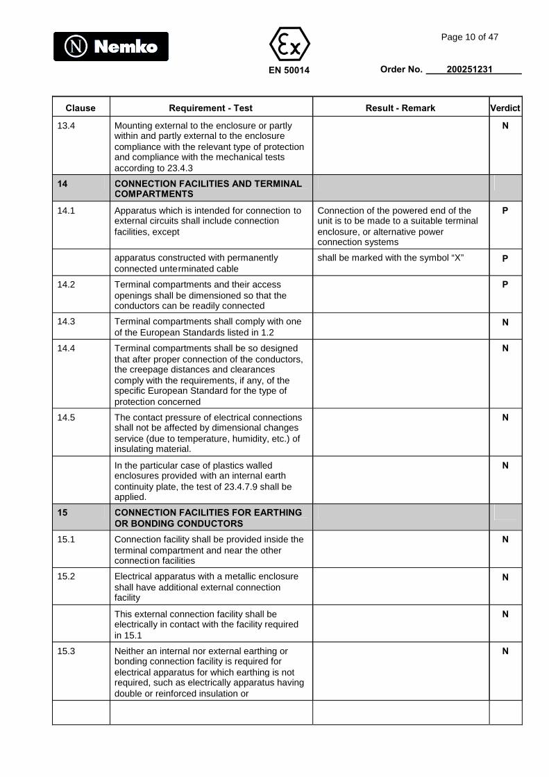
13.4 Mounting external to the enclosure or partlywithin and partly external to the enclosurecompliance with the relevant type of protectionand compliance with the mechanical testsaccording to 23.4.3
N
14 CONNECTION FACILITIES AND TERMINALCOMPARTMENTS
14.1 Apparatus which is intended for connection toexternal circuits shall include connectionfacilities, except
Connection of the powered end of theunit is to be made to a suitable terminalenclosure, or alternative powerconnection systems
P
apparatus constructed with permanentlyconnected unterminated cable
shall be marked with the symbol “X” P
14.2 Terminal compartments and their accessopenings shall be dimensioned so that theconductors can be readily connected
P
14.3 Terminal compartments shall comply with oneof the European Standards listed in 1.2
N
14.4 Terminal compartments shall be so designedthat after proper connection of the conductors,the creepage distances and clearancescomply with the requirements, if any, of thespecific European Standard for the type ofprotection concerned
N
14.5 The contact pressure of electrical connectionsshall not be affected by dimensional changesservice (due to temperature, humidity, etc.) ofinsulating material.
N
In the particular case of plastics walledenclosures provided with an internal earthcontinuity plate, the test of 23.4.7.9 shall beapplied.
N
15 CONNECTION FACILITIES FOR EARTHINGOR BONDING CONDUCTORS
15.1 Connection facility shall be provided inside theterminal compartment and near the otherconnection facilities
N
15.2 Electrical apparatus with a metallic enclosureshall have additional external connectionfacility
N
This external connection facility shall beelectrically in contact with the facility requiredin 15.1
N
15.3 Neither an internal nor external earthing orbonding connection facility is required forelectrical apparatus for which earthing is notrequired, such as electrically apparatus havingdouble or reinforced insulation or
N
EN 50014
Page 11 of 47
Order No. 200251231
Clause Requirement - Test Result - Remark Verdict
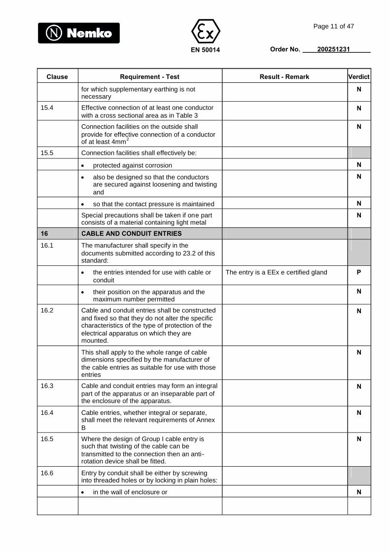
for which supplementary earthing is notnecessary
N
15.4 Effective connection of at least one conductorwith a cross sectional area as in Table 3
N
Connection facilities on the outside shallprovide for effective connection of a conductorof at least 4mm2
N
15.5 Connection facilities shall effectively be:
protected against corrosion N
also be designed so that the conductorsare secured against loosening and twistingand
N
so that the contact pressure is maintained N
Special precautions shall be taken if one partconsists of a material containing light metal
N
16 CABLE AND CONDUIT ENTRIES
16.1 The manufacturer shall specify in thedocuments submitted according to 23.2 of thisstandard:
the entries intended for use with cable orconduit
The entry is a EEx e certified gland P
their position on the apparatus and themaximum number permitted
N
16.2 Cable and conduit entries shall be constructedand fixed so that they do not alter the specificcharacteristics of the type of protection of theelectrical apparatus on which they aremounted.
N
This shall apply to the whole range of cabledimensions specified by the manufacturer ofthe cable entries as suitable for use with thoseentries
N
16.3 Cable and conduit entries may form an integralpart of the apparatus or an inseparable part ofthe enclosure of the apparatus.
N
16.4 Cable entries, whether integral or separate,shall meet the relevant requirements of AnnexB
N
16.5 Where the design of Group I cable entry issuch that twisting of the cable can betransmitted to the connection then an anti-rotation device shall be fitted.
N
16.6 Entry by conduit shall be either by screwinginto threaded holes or by locking in plain holes:
in the wall of enclosure or N

EN 50014
Page 12 of 47
Order No. 200251231
Clause Requirement - Test Result - Remark Verdict
in an adaptor plate designed to be fitted inor on the walls of the enclosure or
N
into a suitable stopping box, integral withor attached to the wall of the enclosure
N
16.7 Blanking elements
satisfy the requirements of the specifictype of protection concerned
N
can be removed only with the aid of a tool N
16.8 When the temperature under rated conditionsis higher than 70C at the cable or conduitentry point, or 80C at the branching point ofthe conductors, the outside of the electricalapparatus shall be marked
N
SUPPLEMENTARY REQUIREMENTS FORCERTAIN ELECTRICAL APPARATUS
17 ROTATING ELECTRICAL MACHINES
External shaft driven cooling fans of rotatingelectrical machines shall be enclosed by afanhood which is not considered to be part ofthe enclosure of the electrical apparatus. Suchfan shall meet the following requirements:
17.1 Ventilating openings for external fans
The degree of protection (IP) of ventilationopenings for external fans of rotating electricalmachines shall be at least:
IP 20 on the air inlet side (EN 60034-5) N
IP 10 on the air outlet side (EN 60034-5) N
For vertical rotating machines rotatingmachines, foreign bodies shall be preventedfrom falling into ventilation openings
N
For group I rotating electrical machines IP10 isadequate only when the openings aredesigned or arranged so that foreign bodieswith dimensions above 12,5mm cannot becarried onto the moving parts of the machineeither by falling vertically or by vibration
N
17.2 Construction and mounting of the ventilatingsystems
Fan and fanhoods and ventilation screensshall be constructed so as to meet therequirements of the resistance to impact testaccording to 23.4.3.2 and the required resultsaccording to 23.4.3.3
N
17.3 Clearances for the ventilating systems
EN 50014
Page 13 of 47
Order No. 200251231
Clause Requirement - Test Result - Remark Verdict
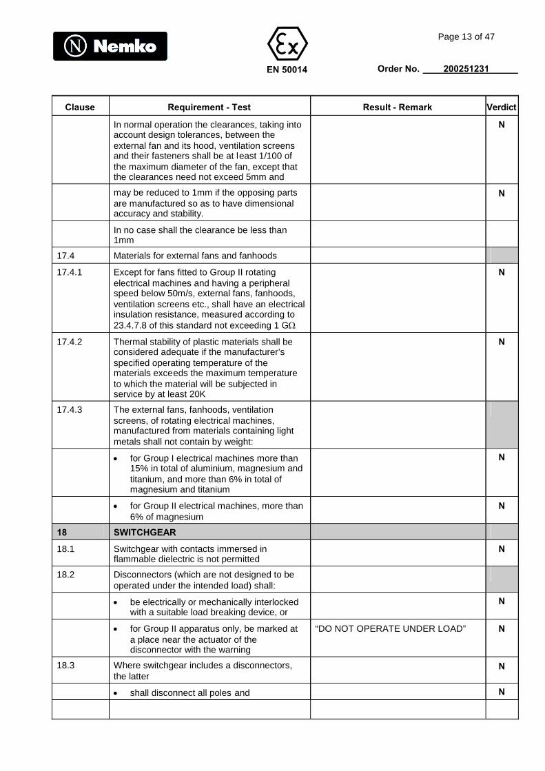
In normal operation the clearances, taking intoaccount design tolerances, between theexternal fan and its hood, ventilation screensand their fasteners shall be at least 1/100 ofthe maximum diameter of the fan, except thatthe clearances need not exceed 5mm and
N
may be reduced to 1mm if the opposing partsare manufactured so as to have dimensionalaccuracy and stability.
N
In no case shall the clearance be less than1mm
17.4 Materials for external fans and fanhoods
17.4.1 Except for fans fitted to Group II rotatingelectrical machines and having a peripheralspeed below 50m/s, external fans, fanhoods,ventilation screens etc., shall have an electricalinsulation resistance, measured according to23.4.7.8 of this standard not exceeding 1 G
N
17.4.2 Thermal stability of plastic materials shall beconsidered adequate if the manufacturer’sspecified operating temperature of thematerials exceeds the maximum temperatureto which the material will be subjected inservice by at least 20K
N
17.4.3 The external fans, fanhoods, ventilationscreens, of rotating electrical machines,manufactured from materials containing lightmetals shall not contain by weight:
for Group I electrical machines more than15% in total of aluminium, magnesium andtitanium, and more than 6% in total ofmagnesium and titanium
N
for Group II electrical machines, more than6% of magnesium
N
18 SWITCHGEAR
18.1 Switchgear with contacts immersed inflammable dielectric is not permitted
N
18.2 Disconnectors (which are not designed to beoperated under the intended load) shall:
be electrically or mechanically interlockedwith a suitable load breaking device, or
N
for Group II apparatus only, be marked ata place near the actuator of thedisconnector with the warning
“DO NOT OPERATE UNDER LOAD” N
18.3 Where switchgear includes a disconnectors,the latter
N
shall disconnect all poles and N

EN 50014
Page 14 of 47
Order No. 200251231
Clause Requirement - Test Result - Remark Verdict
shall be designed so that the position ofdisconnector contacts is visible or
N
their open position shall be reliablyindicated
N
Any interlock between such disconnector andthe cover or door of the switchgear shall allowthis cover or door to be opened only whenseparation of the disconnector contacts iseffective
N
18.4 The operating mechanism of disconnectors forGroup I switchgear shall be capable of beingpadlocked in the open position.
N
18.5 For Group 1 switchgear provision shall bemade to enable short-circuit and earth faultrelays, if used, to latch out.
N
If the switchgear has a local resetting devicewhich is accessible from the outside of theenclosure, its access cover shall have aspecial fastener according to 9.2
N
18.6 Doors an covers giving access to the interior ofenclosures containing remotely operatedcircuits with switching contacts which can bemade or broken by non-manual influence shalleither:
i) be interlocked with a disconnector whichprevents access to the interior unless ithas been operated to disconnectunprotected internal circuits; or
N
ii) be marked with the warning “DO NOT OPEN WHEN ENERGIZED” N
In case of (i) above, where it is intended thatsome internal parts will remain energized afteroperation of the disconnector, those energizedparts shall be protected by either (a) or (b)below:
(a) one of the types of protection listed in 1.2; N
(b) protection as follows:-
clearances and creepage distancesbetween phases (poles) and to earth inaccordance with EN 50019; and
N
an internal supplementary enclosure IP 20so arranged that a tool cannot contact theenergized parts through any openings
N
marking on the internal supplementaryenclosure with the warning
“DO NOT OPEN WHEN ENERGIZED” N

EN 50014
Page 15 of 47
Order No. 200251231
Clause Requirement - Test Result - Remark Verdict
19 FUSES
Enclosures containing fuses shall:
be interlocked so that insertion or removalof replaceable elements can be carried outonly with the supply disconnected and sothat the fuses cannot be energized unti lthe enclosure is correctly closed, or
N
alternatively the apparatus shall bemarked with the warning
“DO NOT OPEN WHEN ENERGIZED” N
20 PLUGS AND SOCKETS
20.1 Plugs and sockets shall comply with either a)or b) below:
a) be interlocked mechanically, or electrically,or otherwise designed so that they cannotbe separated when the contacts areenergized and the contacts cannot beenergized when the plug and socket areseparated, or
N
b) be fixed together by means of specialfasteners according to 9.2 and theapparatus marked with the warning
“DO NOT SEPARATE WHENENERGIZED”
N
20.2 Excluded from requirements N
20.3 Plugs with components remaining energisedwhen not engaged with a socket are notpermitted
N
21 Luminaires
21.1 The source of light of luminaires shall beprotected by a light transmitting cover whichmay be provided with and additional guardcomprising a mesh of not greater than 50mmsquares.
N
If mesh size exceed 50mm squares then theluminaire cover shall be considered asunguarded
N
The light transmitting cover and, if provided,the guard, shall be capable of passing therelevant test according to 23.4.3.1.
N
The mounting of luminaires shall not dependon a single screw.
N
A single eyebolt may be used only if this is anintegral part of the luminaire.
N
EN 50014
Page 16 of 47
Order No. 200251231
Clause Requirement - Test Result - Remark Verdict
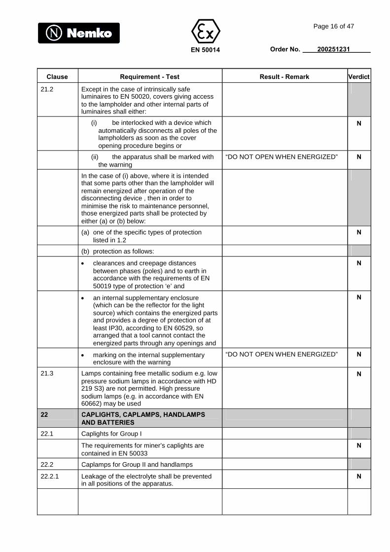
21.2 Except in the case of intrinsically safeluminaires to EN 50020, covers giving accessto the lampholder and other internal parts ofluminaires shall either:
(i) be interlocked with a device whichautomatically disconnects all poles of thelampholders as soon as the coveropening procedure begins or
N
(ii) the apparatus shall be marked withthe warning
“DO NOT OPEN WHEN ENERGIZED” N
In the case of (i) above, where it is intendedthat some parts other than the lampholder willremain energized after operation of thedisconnecting device , then in order tominimise the risk to maintenance personnel,those energized parts shall be protected byeither (a) or (b) below:
(a) one of the specific types of protectionlisted in 1.2
N
(b) protection as follows:
clearances and creepage distancesbetween phases (poles) and to earth inaccordance with the requirements of EN50019 type of protection ‘e’ and
N
an internal supplementary enclosure(which can be the reflector for the lightsource) which contains the energized partsand provides a degree of protection of atleast IP30, according to EN 60529, soarranged that a tool cannot contact theenergized parts through any openings and
N
marking on the internal supplementaryenclosure with the warning
“DO NOT OPEN WHEN ENERGIZED” N
21.3 Lamps containing free metallic sodium e.g. lowpressure sodium lamps in accordance with HD219 S3) are not permitted. High pressuresodium lamps (e.g. in accordance with EN60662) may be used
N
22 CAPLIGHTS, CAPLAMPS, HANDLAMPSAND BATTERIES
22.1 Caplights for Group I
The requirements for miner’s caplights arecontained in EN 50033
N
22.2 Caplamps for Group II and handlamps
22.2.1 Leakage of the electrolyte shall be preventedin all positions of the apparatus.
N

EN 50014
Page 17 of 47
Order No. 200251231
Clause Requirement - Test Result - Remark Verdict
22.2.2 Where the source of light and the source ofsupply are housed in separate enclosures,which are not mechanically connected otherthan by an electric cable, the cable entries andthe connecting cable shall be tested asappropriate according to B.3.1 or B.3.2 ofannex B.
N
22.3 Apparatus incorporating cells and batteries
22.3.1 The requirements in 22.3.1.1 to 22.3.1.12below shall apply for all cells and batteriesincorporated into explosion protectedapparatus:
22.3.1.1 Batteries incorporated into explosion protectedapparatus shall be formed only from cellsconnected in simple series
N
22.3.1.2 Only cell types referred to in published IEC orCENELEC cell standards and having knowncharacteristics shall be used.
N
22.3.1.3 All cells in a battery shall be of the sameelectrochemical system, cell design and ratedcapacity.
N
22.3.1.4 All batteries shall be arranged and operated soas to be within the allowable limits defined bythe cell or battery manufacturer.
N
22.3.1.5 Batteries shall not contain a mixture of primaryand secondary cells.
N
22.3.1.6 Primary and secondary cells or batteries shallnot be used inside the same apparatusenclosure if they are readily interchangeable.
N
22.3.1.7 Primary batteries shall not be re-charged.Where another voltage source exists insideapparatus containing primary batteries andthere is a possibility of interconnection,precautions shall be taken to prevent chargingcurrent passing through them.
N
22.3.1.8 Batteries shall not contain cells made bydifferent manufacturers.
N
22.3.1.9 All cells shall be constructed, or arranged soas to prevent leakage of electrolyte, whichwould adversely affect the type of protection orcomponents which safety depends.
N
22.3.1.10 Only the manufacturer’s recommendedmethod(s) of making electrical connections toa battery shall be used.
N
22.3.1.11 Where a battery is mounted inside apparatusand its orientation is important for safeoperation, the correct orientation of theapparatus shall be indicated on the outside ofthe apparatus enclosure.
N
EN 50014
Page 18 of 47
Order No. 200251231
Clause Requirement - Test Result - Remark Verdict
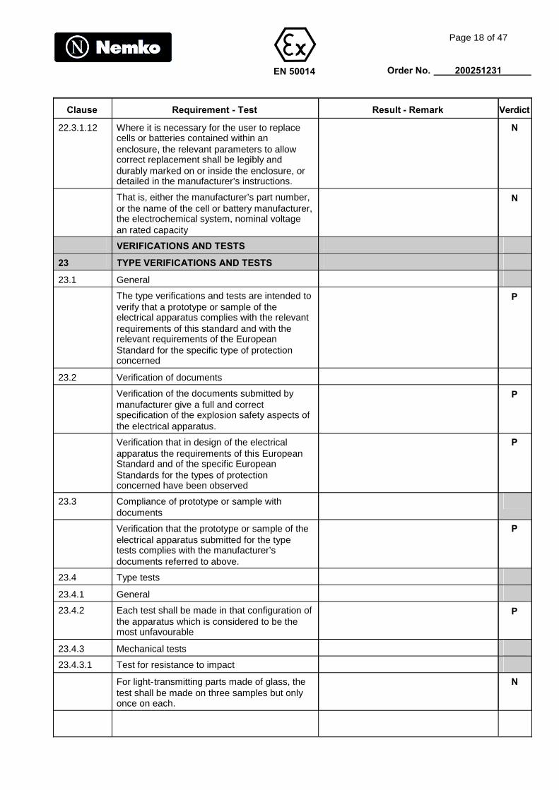
22.3.1.12 Where it is necessary for the user to replacecells or batteries contained within anenclosure, the relevant parameters to allowcorrect replacement shall be legibly anddurably marked on or inside the enclosure, ordetailed in the manufacturer’s instructions.
N
That is, either the manufacturer’s part number,or the name of the cell or battery manufacturer,the electrochemical system, nominal voltagean rated capacity
N
VERIFICATIONS AND TESTS
23 TYPE VERIFICATIONS AND TESTS
23.1 General
The type verifications and tests are intended toverify that a prototype or sample of theelectrical apparatus complies with the relevantrequirements of this standard and with therelevant requirements of the EuropeanStandard for the specific type of protectionconcerned
P
23.2 Verification of documents
Verification of the documents submitted bymanufacturer give a full and correctspecification of the explosion safety aspects ofthe electrical apparatus.
P
Verification that in design of the electricalapparatus the requirements of this EuropeanStandard and of the specific EuropeanStandards for the types of protectionconcerned have been observed
P
23.3 Compliance of prototype or sample withdocuments
Verification that the prototype or sample of theelectrical apparatus submitted for the typetests complies with the manufacturer’sdocuments referred to above.
P
23.4 Type tests
23.4.1 General
23.4.2 Each test shall be made in that configuration ofthe apparatus which is considered to be themost unfavourable
P
23.4.3 Mechanical tests
23.4.3.1 Test for resistance to impact
For light-transmitting parts made of glass, thetest shall be made on three samples but onlyonce on each.
N
EN 50014
Page 19 of 47
Order No. 200251231
Clause Requirement - Test Result - Remark Verdict
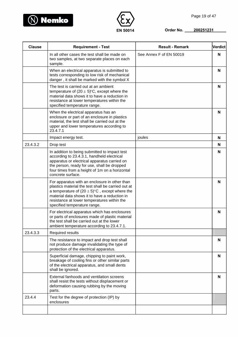
In all other cases the test shall be made ontwo samples, at two separate places on eachsample.
See Annex F of EN 50019 N
When an electrical apparatus is submitted totests corresponding to low risk of mechanicaldanger , it shall be marked with the symbol X
N
The test is carried out at an ambienttemperature of (20 5)C, except where thematerial data shows it to have a reduction inresistance at lower temperatures within thespecified temperature range.
N
When the electrical apparatus has anenclosure or part of an enclosure in plasticsmaterial, the test shall be carried out at theupper and lower temperatures according to23.4.7.1
N
Impact energy test. joules N
23.4.3.2 Drop test N
In addition to being submitted to impact testaccording to 23.4.3.1, handheld electricalapparatus or electrical apparatus carried onthe person, ready for use, shall be droppedfour times from a height of 1m on a horizontalconcrete surface.
N
For apparatus with an enclosure in other thanplastics material the test shall be carried out ata temperature of (20 5)C , except where thematerial data shows it to have a reduction inresistance at lower temperatures within thespecified temperature range.
N
For electrical apparatus which has enclosuresor parts of enclosures made of plastic materialthe test shall be carried out at the lowerambient temperature according to 23.4.7.1.
N
23.4.3.3 Required results
The resistance to impact and drop test shallnot produce damage invalidating the type ofprotection of the electrical apparatus.
N
Superficial damage, chipping to paint work,breakage of cooling fins or other similar partsof the electrical apparatus, and small dentsshall be ignored.
N
External fanhoods and ventilation screensshall resist the tests without displacement ordeformation causing rubbing by the movingparts.
N
23.4.4 Test for the degree of protection (IP) byenclosures
EN 50014
Page 20 of 47
Order No. 200251231
Clause Requirement - Test Result - Remark Verdict
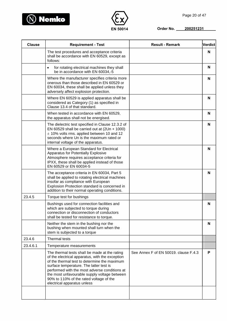
The test procedures and acceptance criteriashall be accordance with EN 60529, except asfollows:
N
for rotating electrical machines they shallbe in accordance with EN 60034,-5
N
Where the manufacturer specifies criteria moreonerous than those described in EN 60529 orEN 60034, these shall be applied unless theyadversely affect explosion protection.
N
Where EN 60529 is applied apparatus shall beconsidered as Category (1) as specified inClause 13.4 of that standard.
N
When tested in accordance with EN 60529,the apparatus shall not be energised.
N
The dielectric test specified in Clause 12.3.2 ofEN 60529 shall be carried out at (2Un + 1000)10% volts rms. applied between 10 and 12seconds where Un is the maximum rated orinternal voltage of the apparatus.
N
Where a European Standard for ElectricalApparatus for Potentially ExplosiveAtmosphere requires acceptance criteria forIPXX, these shall be applied instead of thoseEN 60529 or EN 60034-5
N
The acceptance criteria in EN 60034, Part 5shall be applied to rotating electrical machinesinsofar as compliance with EuropeanExplosion Protection standard is concerned inaddition to their normal operating conditions.
N
23.4.5 Torque test for bushings
Bushings used for connection facilities andwhich are subjected to torque duringconnection or disconnection of conductorsshall be tested for resistance to torque.
N
Neither the stem in the bushing nor thebushing when mounted shall turn when thestem is subjected to a torque
N
23.4.6 Thermal tests
23.4.6.1 Temperature measurements
The thermal tests shall be made at the ratingof the electrical apparatus, with the exceptionof the thermal test to determine the maximumsurface temperature. The latter test isperformed with the most adverse conditions atthe most unfavourable supply voltage between90% to 110% of the rated voltage of theelectrical apparatus unless
See Annex F of EN 50019. clause F.4.3 P

EN 50014
Page 21 of 47
Order No. 200251231
Clause Requirement - Test Result - Remark Verdict
the manufacturer can demonstrate that otherEuropean Standards or CENELECHarmonization Documents prescribe othertolerances for equivalent industrial electricalapparatus
P
The measured maximum surface temperatureshall not exceed:
for Group I electrical apparatus, thosevalues as given in 5.1.1
N
for Group II electrical apparatus whereeach manufactured sample is routinelysubmitted to the thermal test: thetemperature as marked on the electricalapparatus
P
for Group II electrical apparatus where theelectrical apparatus is subjected to typetesting, the marked temperature, or thetemperature class, less 5K for temperatureclasses T6, T5, T4, and T3, and less 10Kfor temperature classes T2 and T1.
See clause F.4.3 of EN 50019 P
The result shall be corrected for the maximumambient temperature specified in the rating.
Ta = 40C P
For electrical apparatus which can normallyused in different positions, the temperature ineach position is to be determined and thehighest temperature is to be considered.
N
When the temperature is determined forcertain positions only the apparatus shall bemarked either by the symbol “X” marking or bya label.
N
Temperature of the hottest point of anyenclosure, or part of enclosure, of plasticmaterial.
N
23.4.6.2 Thermal shock test
Glass parts of luminaires and windows ofelectrical apparatus shall withstand, withoutbraking, a thermal shock caused by a jet ofwater of about 1mm diameter at a temperature(105)C sprayed on them when they are atmaximum service temperature.
N
23.4.7 Test on non-metallic enclosures and of non-metallic parts of enclosures
23.4.7.1 Ambient temperatures during tests
When, according to this European Standard orto the specific European Standards listed in1.2, tests have to be made as a function of thepermissible upper and lower servicetemperatures of the apparatus, the ambienttemperatures shall be:
EN 50014
Page 22 of 47
Order No. 200251231
Clause Requirement - Test Result - Remark Verdict
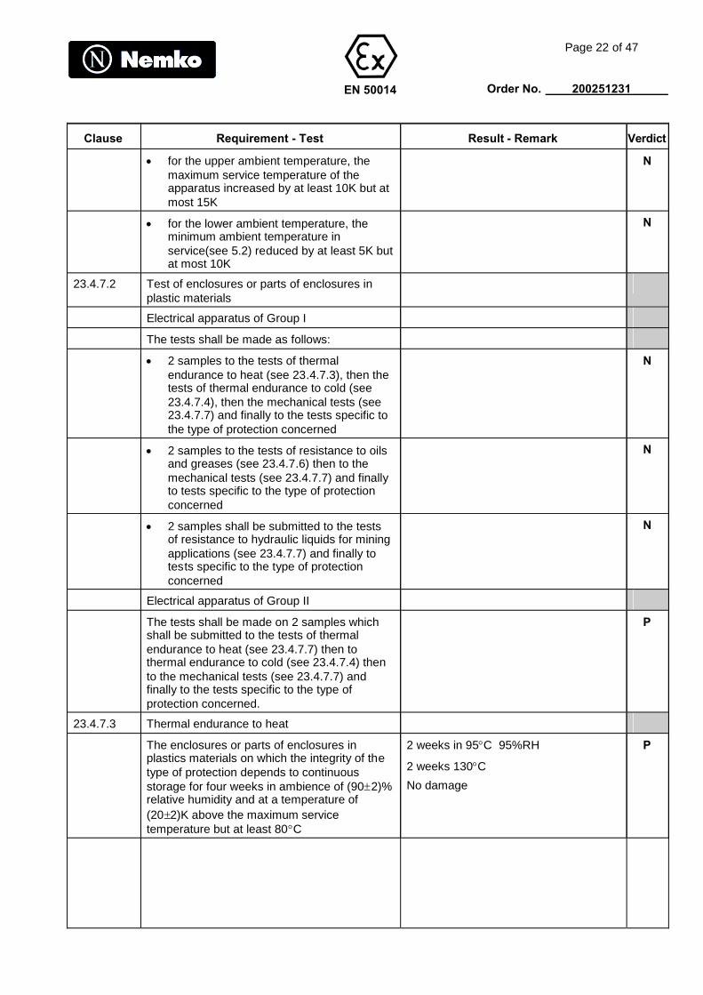
for the upper ambient temperature, themaximum service temperature of theapparatus increased by at least 10K but atmost 15K
N
for the lower ambient temperature, theminimum ambient temperature inservice(see 5.2) reduced by at least 5K butat most 10K
N
23.4.7.2 Test of enclosures or parts of enclosures inplastic materials
Electrical apparatus of Group I
The tests shall be made as follows:
2 samples to the tests of thermalendurance to heat (see 23.4.7.3), then thetests of thermal endurance to cold (see23.4.7.4), then the mechanical tests (see23.4.7.7) and finally to the tests specific tothe type of protection concerned
N
2 samples to the tests of resistance to oilsand greases (see 23.4.7.6) then to themechanical tests (see 23.4.7.7) and finallyto tests specific to the type of protectionconcerned
N
2 samples shall be submitted to the testsof resistance to hydraulic liquids for miningapplications (see 23.4.7.7) and finally totests specific to the type of protectionconcerned
N
Electrical apparatus of Group II
The tests shall be made on 2 samples whichshall be submitted to the tests of thermalendurance to heat (see 23.4.7.7) then tothermal endurance to cold (see 23.4.7.4) thento the mechanical tests (see 23.4.7.7) andfinally to the tests specific to the type ofprotection concerned.
P
23.4.7.3 Thermal endurance to heat
The enclosures or parts of enclosures inplastics materials on which the integrity of thetype of protection depends to continuousstorage for four weeks in ambience of (902)%relative humidity and at a temperature of(202)K above the maximum servicetemperature but at least 80C
2 weeks in 95C 95%RH
2 weeks 130C
No damage
P
EN 50014
Page 23 of 47
Order No. 200251231
Clause Requirement - Test Result - Remark Verdict
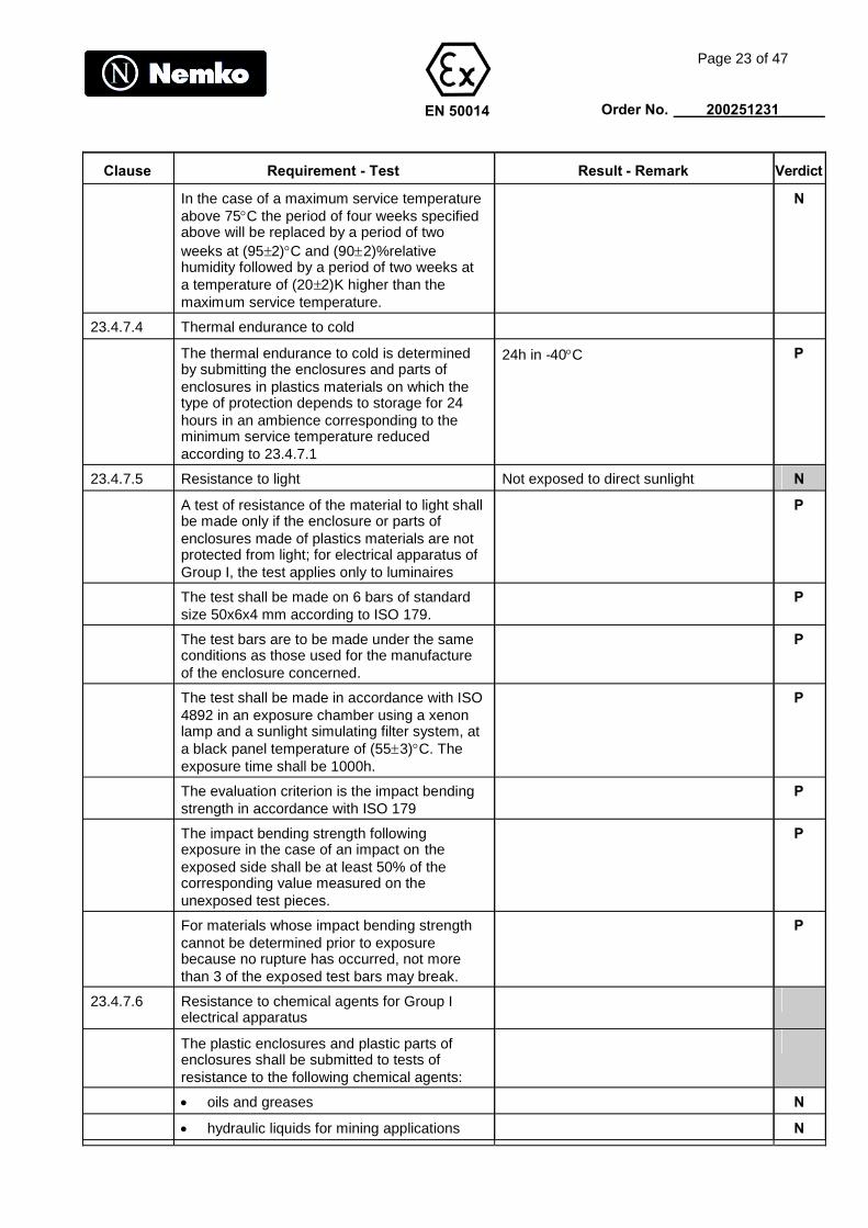
In the case of a maximum service temperatureabove 75C the period of four weeks specifiedabove will be replaced by a period of twoweeks at (952)C and (902)%relativehumidity followed by a period of two weeks ata temperature of (202)K higher than themaximum service temperature.
N
23.4.7.4 Thermal endurance to cold
The thermal endurance to cold is determinedby submitting the enclosures and parts ofenclosures in plastics materials on which thetype of protection depends to storage for 24hours in an ambience corresponding to theminimum service temperature reducedaccording to 23.4.7.1
24h in -40C P
23.4.7.5 Resistance to light Not exposed to direct sunlight N
A test of resistance of the material to light shallbe made only if the enclosure or parts ofenclosures made of plastics materials are notprotected from light; for electrical apparatus ofGroup I, the test applies only to luminaires
P
The test shall be made on 6 bars of standardsize 50x6x4 mm according to ISO 179.
P
The test bars are to be made under the sameconditions as those used for the manufactureof the enclosure concerned.
P
The test shall be made in accordance with ISO4892 in an exposure chamber using a xenonlamp and a sunlight simulating filter system, ata black panel temperature of (553)C. Theexposure time shall be 1000h.
P
The evaluation criterion is the impact bendingstrength in accordance with ISO 179
P
The impact bending strength followingexposure in the case of an impact on theexposed side shall be at least 50% of thecorresponding value measured on theunexposed test pieces.
P
For materials whose impact bending strengthcannot be determined prior to exposurebecause no rupture has occurred, not morethan 3 of the exposed test bars may break.
P
23.4.7.6 Resistance to chemical agents for Group Ielectrical apparatus
The plastic enclosures and plastic parts ofenclosures shall be submitted to tests ofresistance to the following chemical agents:
oils and greases N
hydraulic liquids for mining applications N

EN 50014
Page 24 of 47
Order No. 200251231
Clause Requirement - Test Result - Remark Verdict
The relevant tests shall be made on foursamples of enclosure sealed against theintrusion of test liquids into the enclosure:
N
two samples shall remain from (24 2)hours in oil No 2 according to the annex“Reference immersion liquids” of ISO1817, at a temperature of 50C.
N
the two other samples shall remain for (242) hours in a fire resistant hydraulic fluid,rated for operating at temperaturesbetween –20C and + 60C , comprisingan aqueous solution of polymer in 35%water, at a temperature of (50 2)C.
N
At the end of the test, the enclosure samplesshall be removed from the liquid bath, wipedand then stored for (242) hours in laboratoryatmosphere. Each enclosure shall pass themechanical tests according to 23.4.7.7.
N
If one or more of the enclosure samples do notwithstand these mechanical tests, specialconditions for safe use shall be stated in thecertificate and the marking of the electricalapparatus shall include the symbol “X”.
N
23.4.7.7 Mechanical tests
The mechanical tests specified in 23.4.3 shallbe carried out on the enclosures and,additionally, in the case of plastic enclosures,according to 23.4.7.2
P
The following detailed conditions shall beobserved:
a) The test for resistance to impactThe place of impact shall be on theexternal parts exposed to impact. If theenclosure of non-metallic material isprotected by another enclosure, only theexternal parts of assembly shall besubjected to the resistance to impact tests.The test shall first be made at the highesttemperature, then at the lowesttemperature, according to 23.4.7.1.
See clause F.1.1 of EN 50019 P
b) Drop testThe drop test for electrical apparatuswhich is held in the hand or carried on theperson, shall be made at the lowesttemperature, according to 23.4.7.1
N
23.4.7.8 Insulation resistance test of parts of enclosuresof plastic materials
Test piece cleaned with distilled water, thenwith isopropyl alcohol, then once more withdestilled water before being dried.
N

EN 50014
Page 25 of 47
Order No. 200251231
Clause Requirement - Test Result - Remark Verdict
Test piece with painted electrodes conditionedfor 24 hours according to 7.3
N
Test result see 7.3 N
23.4.7.9 Earth continuity test via non-metallic enclosure
The material from which the enclosure ismanufactured may be tested as a completeenclosure, a part of an enclosure, or as asample of the material from which theenclosure is made, provided that the relevantcritical dimensions of the sample are the sameas those of the enclosure.
N
The cable gland is represented by a20mm(nominal) diameter test barmanufactured from brass carrying an ISOmetric thread with a tolerance class 6g, 1,5mmpitch (IEC 60423).
N
Complete earth plates or parts of earth platesthat are intended to be used with the enclosureshall be used for this test
N
If the earth plate is intended to have aclearance hole, the hole provide in thesamples used for the test shall be between22mm and 23mm diameter and the method ofassembly shall ensure that the screw thread ofthe test bar does not make contact directlyinside of the clearance hole.
N
The components are assembled as shown infigure 5. The torque applied to each pair of thenuts in turn shall be 10Nm(10%).
N
The hole in the wall may be a plain throughhole or a tapped hole having a thread formcompatible with the test bar.
N
After the test sample has been assembled itshall be subjected to the conditions for the testfor thermal endurance to heat as described in23.4.7.3.
N
This shall be followed by a further period of 14days in an air oven at a temperature of 80C.
N
On completion of the conditioning theresistance between the earth plates or parts ofearth plates shall be calculated by passing adirect current of 10A between the earth platesand measuring the voltage drop betweenthem.
N
The plastic material that has been tested inthis manner is deemed to be satisfactory if theresistance between the earth plates or parts ofearth plates does not exceed 1 x 10⁻³ ohms.
N

EN 50014
Page 26 of 47
Order No. 200251231
Clause Requirement - Test Result - Remark Verdict
23.4.8 Tests in explosive mixtures
The European Standard for the specific type ofprotection states if tests in explosive mixturesare required and specifies the explosivemixtures.
N
24 Routine verification and tests
The manufacturer shall carry out routineverifications and tests necessary to ensure thatthe electrical apparatus produced complieswith specifications submitted to the testingstation together with the prototype or sample.He shall also carry out any routine verificationsand tests required by the European Standardslisted in 1.2
See clause 7 of EN50019 P
25 Manufacturer's responsibility
By marking the electrical apparatus inaccordance with clause 27 the manufacturerattests on his own responsibility that:
the electrical apparatus has beenconstructed in accordance with theprinciples of good engineering practice insafety matters
P
the routine verifications and tests in clause24 have been successfully completed andthat the product complies with thespecification submitted to the testingstation.
P
26 Verifications and tests on modified orrepaired electrical apparatus
Modifications made on the electrical apparatusaffecting the integrity of the type of protectionor the temperature of the apparatus shall bepermitted only if the modified apparatus isresubmitted to a testing station.
P
27 SECTION V. MARKING
27.1 The electrical apparatus shall be marked onthe main part in a visible place.
P
This marking shall be legible and durabletaking in to account possible chemicalcorrosion.
P
27.2 The marking shall include:
a) the name of the manufacturer or hisregistered trade mark
PWL P
b) the manufacturer’s type identification SRF and SRM P
c) the symbol EEx EEx P
d) the symbol for each type of protectionused
e P
EN 50014
Page 27 of 47
Order No. 200251231
Clause Requirement - Test Result - Remark Verdict
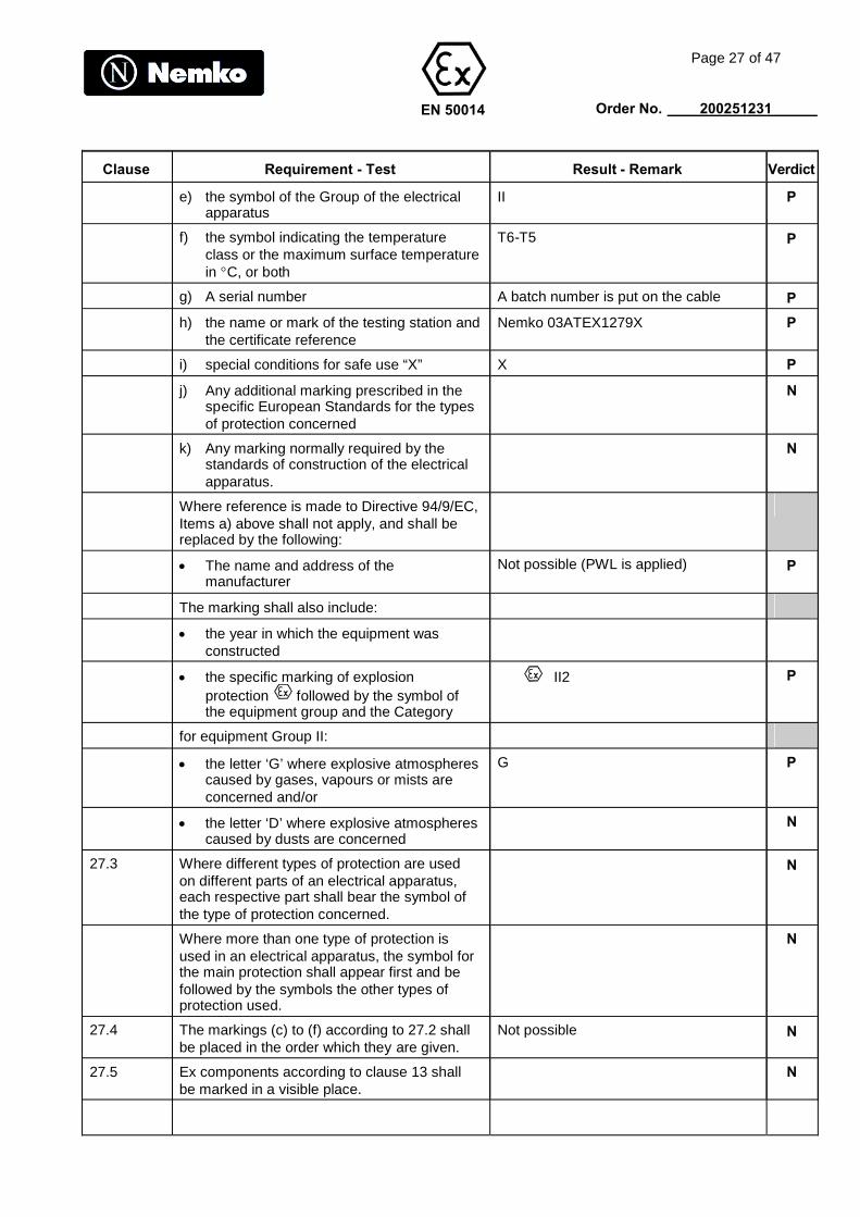
e) the symbol of the Group of the electricalapparatus
II P
f) the symbol indicating the temperatureclass or the maximum surface temperaturein C, or both
T6-T5 P
g) A serial number A batch number is put on the cable P
h) the name or mark of the testing station andthe certificate reference
Nemko 03ATEX1279X P
i) special conditions for safe use “X” X P
j) Any additional marking prescribed in thespecific European Standards for the typesof protection concerned
N
k) Any marking normally required by thestandards of construction of the electricalapparatus.
N
Where reference is made to Directive 94/9/EC,Items a) above shall not apply, and shall bereplaced by the following:
The name and address of themanufacturer
Not possible (PWL is applied) P
The marking shall also include:
the year in which the equipment wasconstructed
the specific marking of explosionprotection followed by the symbol ofthe equipment group and the Category
II2 P
for equipment Group II:
the letter ‘G’ where explosive atmospherescaused by gases, vapours or mists areconcerned and/or
G P
the letter ‘D’ where explosive atmospherescaused by dusts are concerned
N
27.3 Where different types of protection are usedon different parts of an electrical apparatus,each respective part shall bear the symbol ofthe type of protection concerned.
N
Where more than one type of protection isused in an electrical apparatus, the symbol forthe main protection shall appear first and befollowed by the symbols the other types ofprotection used.
N
27.4 The markings (c) to (f) according to 27.2 shallbe placed in the order which they are given.
Not possible N
27.5 Ex components according to clause 13 shallbe marked in a visible place.
N
EN 50014
Page 28 of 47
Order No. 200251231
Clause Requirement - Test Result - Remark Verdict
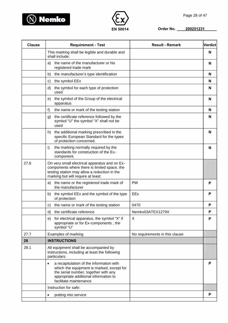
This marking shall be legible and durable andshall include:
N
a) the name of the manufacturer or hisregistered trade mark
N
b) the manufacturer’s type identification N
c) the symbol EEx N
d) the symbol for each type of protectionused
N
e) the symbol of the Group of the electricalapparatus
N
f) the name or mark of the testing station N
g) the certificate reference followed by thesymbol “U” the symbol “X” shall not beused
N
h) the additional marking prescribed in thespecific European Standard for the typesof protection concerned.
N
i) the marking normally required by thestandards for construction of the Ex-component.
N
27.6 On very small electrical apparatus and on Ex-components where there is limited space, thetesting station may allow a reduction in themarking but will require at least:
a) the name or the registered trade mark ofthe manufacturer
PW P
b) the symbol EEx and the symbol of the typeof protection
EEx P
c) the name or mark of the testing station 0470 P
d) the certificate reference Nemko03ATEX1279X P
e) for electrical apparatus, the symbol “X” ifappropriate or for Ex-components , thesymbol “U”
X P
27.7 Examples of marking No requirements in this clause
28 INSTRUCTIONS
28.1 All equipment shall be accompanied byinstructions, including at least the followingparticulars:
a recapitulation of the information withwhich the equipment is marked, except forthe serial number, together with anyappropriate additional information tofacilitate maintenance
P
Instruction for safe:
putting into service P
EN 50014
Page 29 of 47
Order No. 200251231
Clause Requirement - Test Result - Remark Verdict
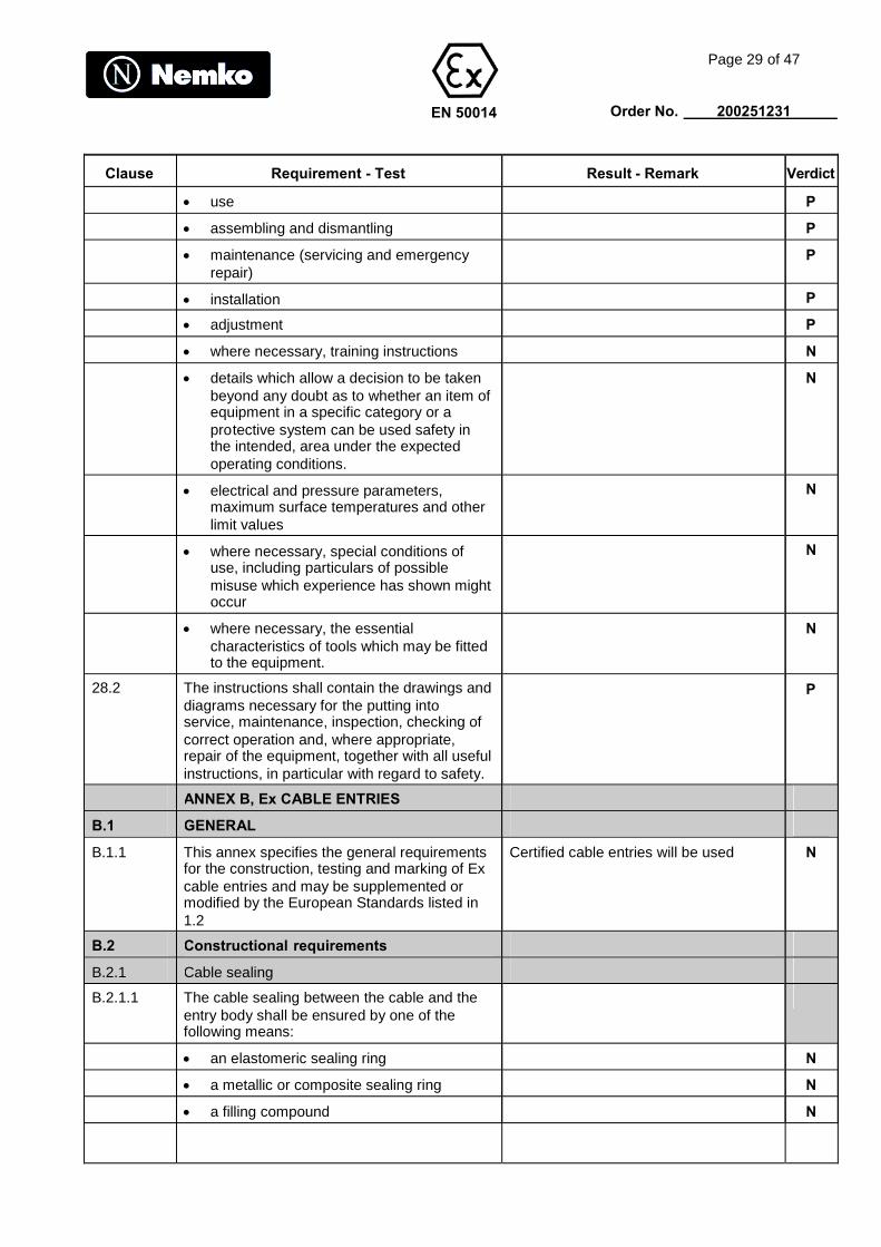
use P
assembling and dismantling P
maintenance (servicing and emergencyrepair)
P
installation P
adjustment P
where necessary, training instructions N
details which allow a decision to be takenbeyond any doubt as to whether an item ofequipment in a specific category or aprotective system can be used safety inthe intended, area under the expectedoperating conditions.
N
electrical and pressure parameters,maximum surface temperatures and otherlimit values
N
where necessary, special conditions ofuse, including particulars of possiblemisuse which experience has shown mightoccur
N
where necessary, the essentialcharacteristics of tools which may be fittedto the equipment.
N
28.2 The instructions shall contain the drawings anddiagrams necessary for the putting intoservice, maintenance, inspection, checking ofcorrect operation and, where appropriate,repair of the equipment, together with all usefulinstructions, in particular with regard to safety.
P
ANNEX B, Ex CABLE ENTRIES
B.1 GENERAL
B.1.1 This annex specifies the general requirementsfor the construction, testing and marking of Excable entries and may be supplemented ormodified by the European Standards listed in1.2
Certified cable entries will be used N
B.2 Constructional requirements
B.2.1 Cable sealing
B.2.1.1 The cable sealing between the cable and theentry body shall be ensured by one of thefollowing means:
an elastomeric sealing ring N
a metallic or composite sealing ring N
a filling compound N
EN 50014
Page 30 of 47
Order No. 200251231
Clause Requirement - Test Result - Remark Verdict
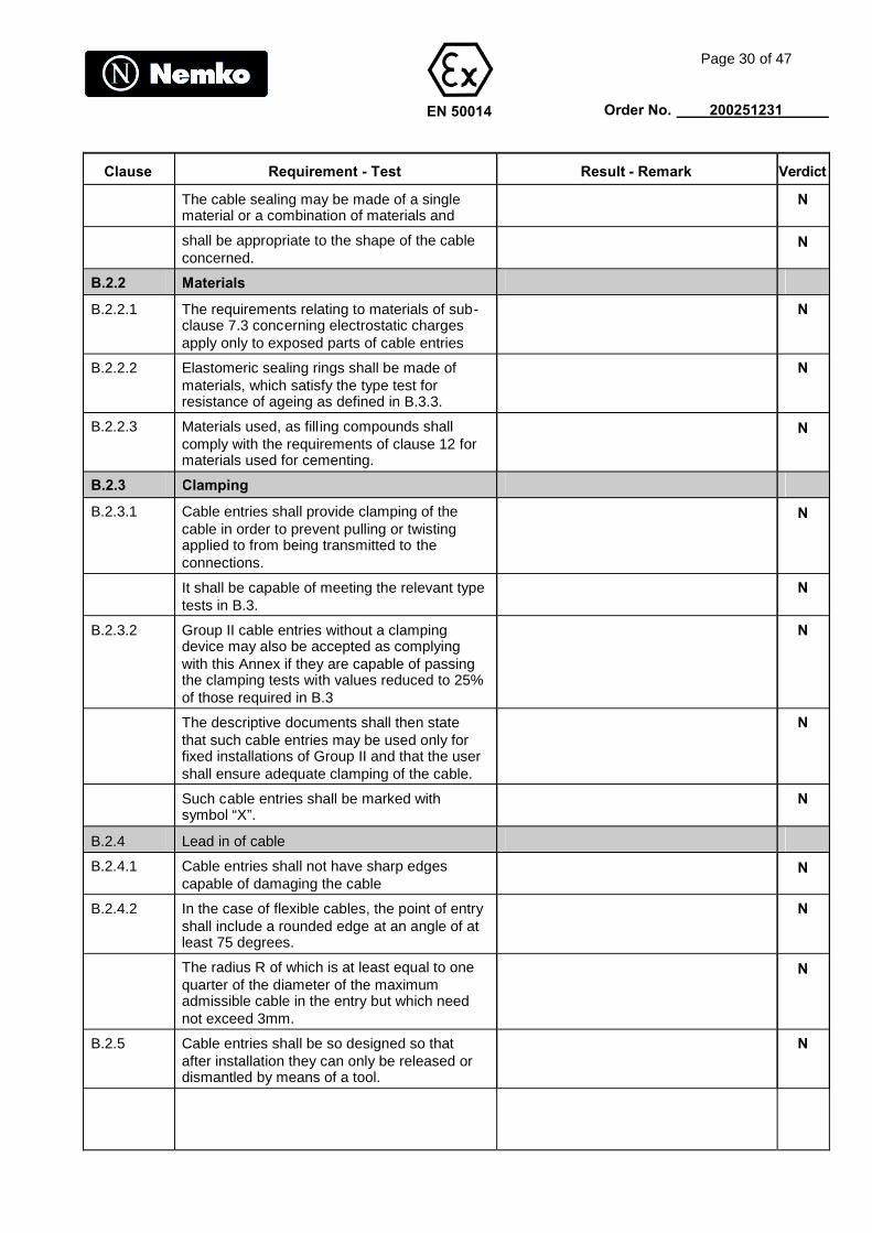
The cable sealing may be made of a singlematerial or a combination of materials and
N
shall be appropriate to the shape of the cableconcerned.
N
B.2.2 Materials
B.2.2.1 The requirements relating to materials of sub-clause 7.3 concerning electrostatic chargesapply only to exposed parts of cable entries
N
B.2.2.2 Elastomeric sealing rings shall be made ofmaterials, which satisfy the type test forresistance of ageing as defined in B.3.3.
N
B.2.2.3 Materials used, as fill ing compounds shallcomply with the requirements of clause 12 formaterials used for cementing.
N
B.2.3 Clamping
B.2.3.1 Cable entries shall provide clamping of thecable in order to prevent pulling or twistingapplied to from being transmitted to theconnections.
N
It shall be capable of meeting the relevant typetests in B.3.
N
B.2.3.2 Group II cable entries without a clampingdevice may also be accepted as complyingwith this Annex if they are capable of passingthe clamping tests with values reduced to 25%of those required in B.3
N
The descriptive documents shall then statethat such cable entries may be used only forfixed installations of Group II and that the usershall ensure adequate clamping of the cable.
N
Such cable entries shall be marked withsymbol “X”.
N
B.2.4 Lead in of cable
B.2.4.1 Cable entries shall not have sharp edgescapable of damaging the cable
N
B.2.4.2 In the case of flexible cables, the point of entryshall include a rounded edge at an angle of atleast 75 degrees.
N
The radius R of which is at least equal to onequarter of the diameter of the maximumadmissible cable in the entry but which neednot exceed 3mm.
N
B.2.5 Cable entries shall be so designed so thatafter installation they can only be released ordismantled by means of a tool.
N

EN 50014
Page 31 of 47
Order No. 200251231
Clause Requirement - Test Result - Remark Verdict
B.2.6 The means of fixing cable entries toenclosures shall be capable of retaining thecable entry when subjected to the mechanicaltests of clamping and resistance to impact inB.3.
N
B.2.7 Cable entries shall be capable of providingwith enclosure on which they are fixed, thesame degree of protection as required for theenclosure See B.3.5.
N
B.3 TYPE TESTS
B.3.1 Test of clamping of non-armoured and braidedcables
N
B.3.1.1 Cable entries with clamping by the sealing ring N
The tests of clamping shall be carried outusing for each type of cable entry 2 sealingrings: one equal to the smallest admissiblesize and other equal to the greatest admissiblesize
N
In the case of elastomeric sealing rings forcircular cables, each ring is mounted on aclean , dry, polished cylindrical mild steelmandrel equal to the smallest cable diameterallowable in the ring and specified by themanufacturer of the cable entry
N
For non-circular cables, the ring shall bemounted on a sample of dry, clean cable ofdimension equal to the size specified by themanufacturer of the cable entry.
N
In the case of metallic sealing rings, each ringis mounted on a sample of clean, dry cable ofa diameter equal to the smallest diameterallowable in the ring and specified by themanufacturer of the cable entry.
N
A torque is applied to the screws or to the nutin order to obtain the compression of thesealing ring and prevent slipping of themandrel or cable when the force applied to it isthe value in Newtons equal to:
20 times the value in millimetres of thediameter of the mandrel or cable when thecable entry is designed for round cable or
N
6 times the value in millimetres of theperimeter of the cable entry is designed fornon-circular cable
N
B.3.1.2 Cable entries with clamping by fillingcompound
The tests of clamping shall be carried outusing two samples of clean, dry cable; oneequal to the smallest admissible size and theother equal to the greatest admissible size
N

EN 50014
Page 32 of 47
Order No. 200251231
Clause Requirement - Test Result - Remark Verdict
The filling compound shall prevent slipping ofthe cable when the force applied to it is thevalue in Newtons equal to:
20 times the value in millimetres of thediameter of the mandrel or cable when thecable entry is designed for circular cable or
N
6 times the value in millimetres of theperimeter of the cable entry is designed fornon-circular cable
N
B.3.1.3 Cable entries with clamping by means of aclamping device
The test of clamping shall be carried out usingfor each type of cable entry clamping devicesof the different allowable sizes.
N
The clamping device with the cable and thesealing ring whose size is equal to the largestsize of cable allowable in that ring specified bythe manufacturer of the cable entry, are thenfitted in the cable entry; the entry is thenassembled with compression of the sealingring and tightening of the clamping device.
N
A torque is applied to the screws or to the nutin order to obtain the compression of thesealing ring and prevent slipping of themandrel or cable when the force applied to it isthe value in Newtons equal to:
20 times the value in millimetres of thediameter of the mandrel or cable when thecable entry is designed for round cable or
N
6 times the value in millimetres of theperimeter of the cable entry is designed fornon-circular cable
N
B.3.1.4 Tensile test
The prepared sample is mounted on a tensiletesting machine and a constant force equal tothat defined above is then applied for 6 hours.The test is carried out at ambient temperature(20 5)C.
N
The clamping assured by the sealing ring,filling compound, or by the clamping device isacceptable if slipping of the mandrel or cablesample is not more than 6mm.
N
B.3.1.5 Mechanical strength
After the tensile test, the cable entry isremoved from the tensile testing machine andsubmitted to the following tests andexaminations, as appropriate
EN 50014
Page 33 of 47
Order No. 200251231
Clause Requirement - Test Result - Remark Verdict
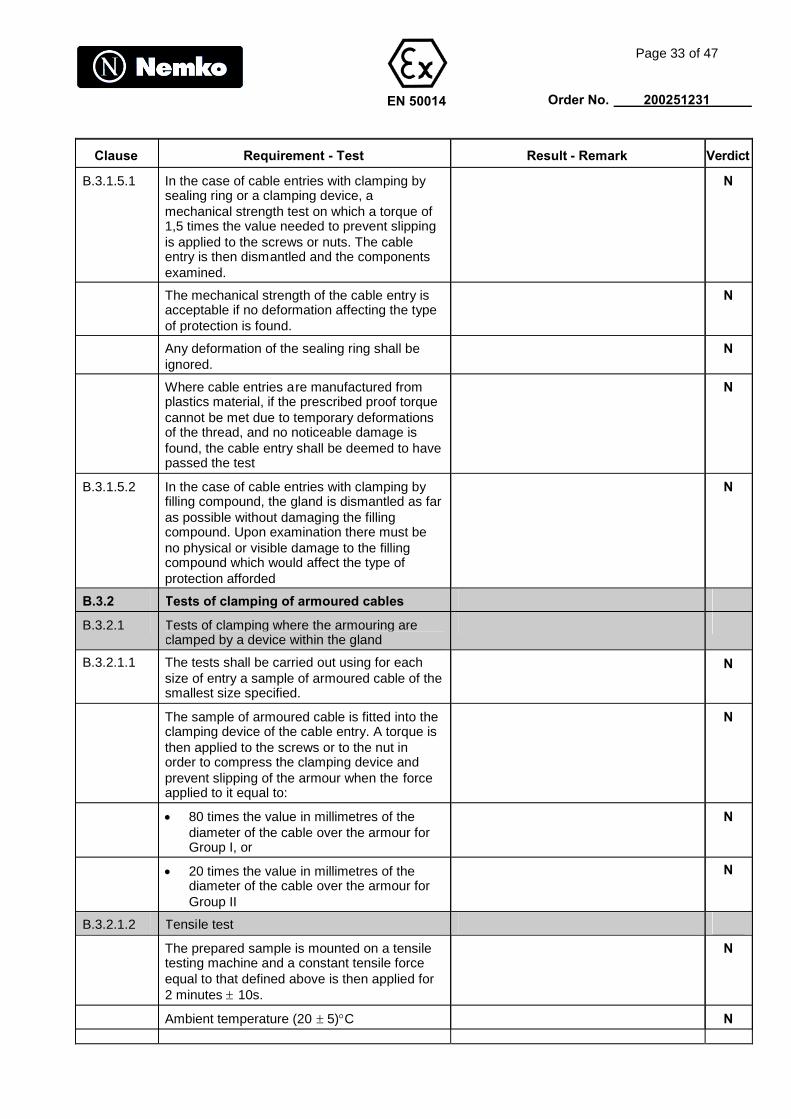
B.3.1.5.1 In the case of cable entries with clamping bysealing ring or a clamping device, amechanical strength test on which a torque of1,5 times the value needed to prevent slippingis applied to the screws or nuts. The cableentry is then dismantled and the componentsexamined.
N
The mechanical strength of the cable entry isacceptable if no deformation affecting the typeof protection is found.
N
Any deformation of the sealing ring shall beignored.
N
Where cable entries are manufactured fromplastics material, if the prescribed proof torquecannot be met due to temporary deformationsof the thread, and no noticeable damage isfound, the cable entry shall be deemed to havepassed the test
N
B.3.1.5.2 In the case of cable entries with clamping byfilling compound, the gland is dismantled as faras possible without damaging the fillingcompound. Upon examination there must beno physical or visible damage to the fillingcompound which would affect the type ofprotection afforded
N
B.3.2 Tests of clamping of armoured cables
B.3.2.1 Tests of clamping where the armouring areclamped by a device within the gland
B.3.2.1.1 The tests shall be carried out using for eachsize of entry a sample of armoured cable of thesmallest size specified.
N
The sample of armoured cable is fitted into theclamping device of the cable entry. A torque isthen applied to the screws or to the nut inorder to compress the clamping device andprevent slipping of the armour when the forceapplied to it equal to:
N
80 times the value in millimetres of thediameter of the cable over the armour forGroup I, or
N
20 times the value in millimetres of thediameter of the cable over the armour forGroup II
N
B.3.2.1.2 Tensile test
The prepared sample is mounted on a tensiletesting machine and a constant tensile forceequal to that defined above is then applied for2 minutes 10s.
N
Ambient temperature (20 5)C N

EN 50014
Page 34 of 47
Order No. 200251231
Clause Requirement - Test Result - Remark Verdict
The clamping assured by the clamping deviceis acceptable if the slipping of the armour iseffectively zero
N
B.3.2.1.3 Mechanical strength
Where screws and nuts are fitted they shall betightened to 1,5 times the values in B.3.2.1.1and then the cable entry dismantled.
N
The mechanical strength is acceptable if nodeformation affecting the type of protection isfound.
N
B.3.2.2 Tests of clamping where the armouring are notclamped by a device within the gland
The cable entry shall be treated as if it is a nonarmoured type according to B.3.1
N
B.3.3 Ageing test for material used for elastomericsealing rings
Test pieces in accordance with the standardsISO 48 and ISO 1818
N
The hardness is determined in accordancewith the same standards at ambienttemperature
N
The test piece is the placed in an oven inwhich the temperature is maintained at(100 5)C without interruption
N
then they are then kept for at least 24 hours atambient temperature
N
then placed in a refrigerator in which thetemperature is maintained at (-202)C for atleast 48 hours without interruption
N
they are finally kept for at least 24 hours atambient temperature.
N
The hardness is then determined again.At the end of the test procedure the variation inhardness, expressed in IRHD units asspecified in the ISO standards given above,shall not exceed 20% of the hardness beforeageing
N
Where a cable entry is intended to be used attemperature above that foreseen in 16.8, theageing test shall be carried out at atemperature (20 5)K above the declaredmaximum operating temperature at thebranching point of the conductors. Where acable entry is intended to be used in anambient temperature below -20C, the test inthe refrigerator shall be carried out at thedeclared minimum ambient temperature, with atolerance of 2C.
N
EN 50014
Page 35 of 47
Order No. 200251231
Clause Requirement - Test Result - Remark Verdict
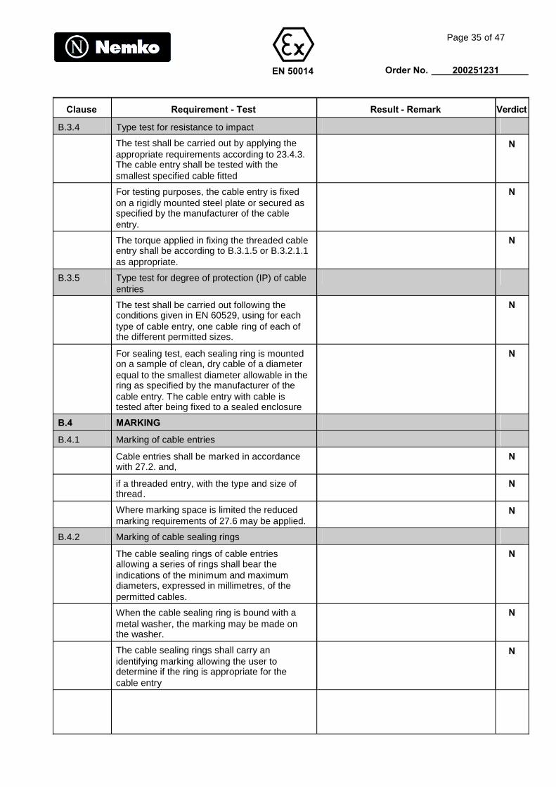
B.3.4 Type test for resistance to impact
The test shall be carried out by applying theappropriate requirements according to 23.4.3.The cable entry shall be tested with thesmallest specified cable fitted
N
For testing purposes, the cable entry is fixedon a rigidly mounted steel plate or secured asspecified by the manufacturer of the cableentry.
N
The torque applied in fixing the threaded cableentry shall be according to B.3.1.5 or B.3.2.1.1as appropriate.
N
B.3.5 Type test for degree of protection (IP) of cableentries
The test shall be carried out following theconditions given in EN 60529, using for eachtype of cable entry, one cable ring of each ofthe different permitted sizes.
N
For sealing test, each sealing ring is mountedon a sample of clean, dry cable of a diameterequal to the smallest diameter allowable in thering as specified by the manufacturer of thecable entry. The cable entry with cable istested after being fixed to a sealed enclosure
N
B.4 MARKING
B.4.1 Marking of cable entries
Cable entries shall be marked in accordancewith 27.2. and,
N
if a threaded entry, with the type and size ofthread.
N
Where marking space is limited the reducedmarking requirements of 27.6 may be applied.
N
B.4.2 Marking of cable sealing rings
The cable sealing rings of cable entriesallowing a series of rings shall bear theindications of the minimum and maximumdiameters, expressed in millimetres, of thepermitted cables.
N
When the cable sealing ring is bound with ametal washer, the marking may be made onthe washer.
N
The cable sealing rings shall carry anidentifying marking allowing the user todetermine if the ring is appropriate for thecable entry
N

EN 50014
Page 36 of 47
Order No. 200251231
Clause Requirement - Test Result - Remark Verdict
Where the entry and the ring are intended tobe used at temperatures outside the range-20C to + 80C and have been testedaccordingly, as specified in B.3.3, they shall bemarked with the temperature range.
N
EN 50019ANNEX
Page 37 of 47
Order No. 200251231
Clause Requirement - Test Result - Remark Verdict
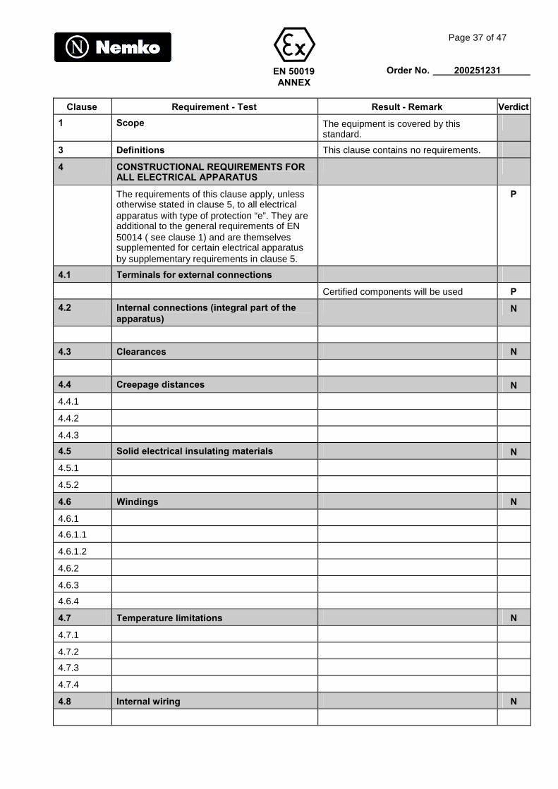
1 Scope The equipment is covered by thisstandard.
3 Definitions This clause contains no requirements.
4 CONSTRUCTIONAL REQUIREMENTS FORALL ELECTRICAL APPARATUS
The requirements of this clause apply, unlessotherwise stated in clause 5, to all electricalapparatus with type of protection “e”. They areadditional to the general requirements of EN50014 ( see clause 1) and are themselvessupplemented for certain electrical apparatusby supplementary requirements in clause 5.
P
4.1 Terminals for external connections
Certified components will be used P
4.2 Internal connections (integral part of theapparatus)
N
4.3 Clearances N
4.4 Creepage distances N
4.4.1
4.4.2
4.4.3
4.5 Solid electrical insulating materials N
4.5.1
4.5.2
4.6 Windings N
4.6.1
4.6.1.1
4.6.1.2
4.6.2
4.6.3
4.6.4
4.7 Temperature limitations N
4.7.1
4.7.2
4.7.3
4.7.4
4.8 Internal wiring N
EN 50019ANNEX
Page 38 of 47
Order No. 200251231
Clause Requirement - Test Result - Remark Verdict
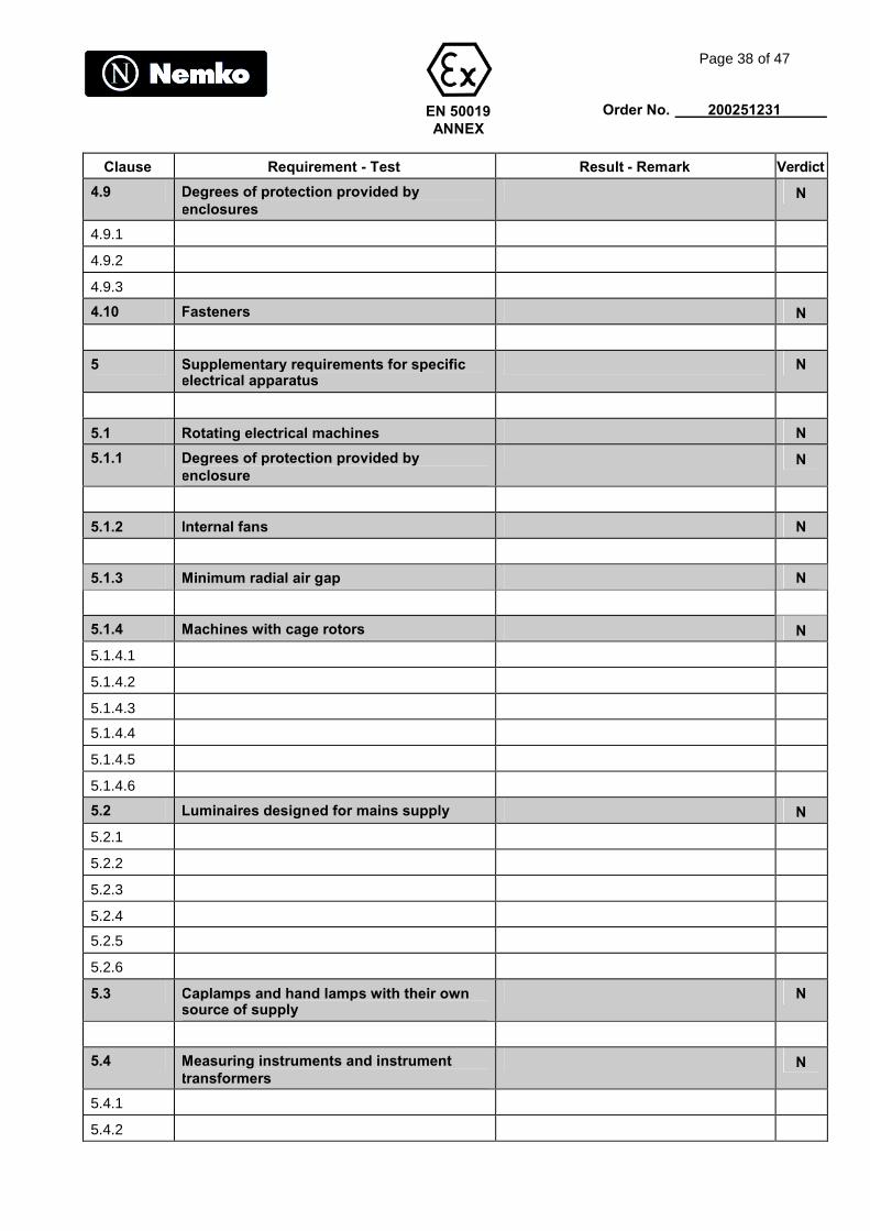
4.9 Degrees of protection provided byenclosures
N
4.9.1
4.9.2
4.9.3
4.10 Fasteners N
5 Supplementary requirements for specificelectrical apparatus
N
5.1 Rotating electrical machines N
5.1.1 Degrees of protection provided byenclosure
N
5.1.2 Internal fans N
5.1.3 Minimum radial air gap N
5.1.4 Machines with cage rotors N
5.1.4.1
5.1.4.2
5.1.4.3
5.1.4.4
5.1.4.5
5.1.4.6
5.2 Luminaires designed for mains supply N
5.2.1
5.2.2
5.2.3
5.2.4
5.2.5
5.2.6
5.3 Caplamps and hand lamps with their ownsource of supply
N
5.4 Measuring instruments and instrumenttransformers
N
5.4.1
5.4.2

EN 50019ANNEX
Page 39 of 47
Order No. 200251231
Clause Requirement - Test Result - Remark Verdict
5.4.3
5.4.4
5.4.5
5.4.6
5.5 Transformers other than instrumenttransformers
N
5.6 Cells and batteries N
5.6.1 Acceptable electrochemical systems N
5.6.2 Classification
5.6.3 General Requirements N
5.6.3.1
5.6.3.2
5.6.3.3
5.6.3.4
5.6.3.5
5.6.3.6
5.6.3.7
5.6.3.8
5.6.3.9
5.6.3.10
5.6.3.11
5.6.4 Charging in hazardous areas N
5.6.4.1
5.6.4.2
5.6.4.3
5.6.4.4
5.6.4.5
5.6.5 Discharge og cells N
5.6.5.1
5.6.5.2
5.6.5.3
5.6.5.4
5.6.5.5
5.6.6 Incorporation of other protection concepts N
EN 50019ANNEX
Page 40 of 47
Order No. 200251231
Clause Requirement - Test Result - Remark Verdict
5.6.6.1
5.6.6.2
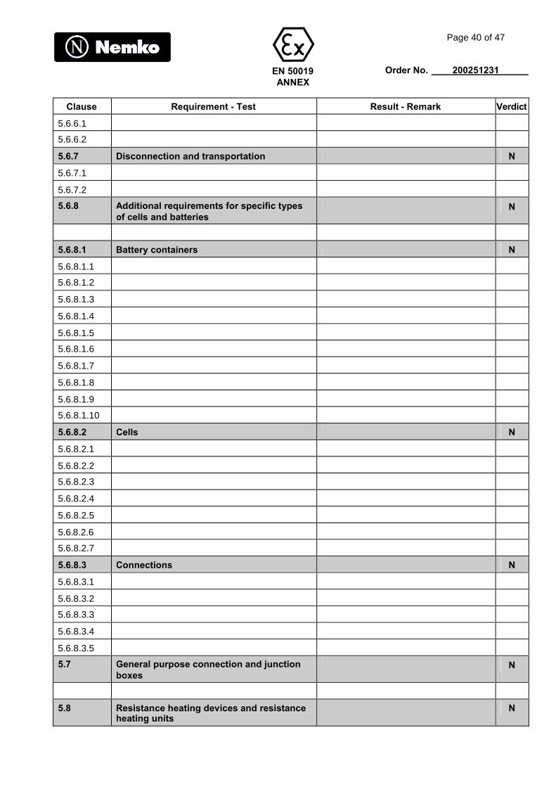
5.6.7 Disconnection and transportation N
5.6.7.1
5.6.7.2
5.6.8 Additional requirements for specific typesof cells and batteries
N
5.6.8.1 Battery containers N
5.6.8.1.1
5.6.8.1.2
5.6.8.1.3
5.6.8.1.4
5.6.8.1.5
5.6.8.1.6
5.6.8.1.7
5.6.8.1.8
5.6.8.1.9
5.6.8.1.10
5.6.8.2 Cells N
5.6.8.2.1
5.6.8.2.2
5.6.8.2.3
5.6.8.2.4
5.6.8.2.5
5.6.8.2.6
5.6.8.2.7
5.6.8.3 Connections N
5.6.8.3.1
5.6.8.3.2
5.6.8.3.3
5.6.8.3.4
5.6.8.3.5
5.7 General purpose connection and junctionboxes
N
5.8 Resistance heating devices and resistanceheating units
N
EN 50019ANNEX
Page 41 of 47
Order No. 200251231
Clause Requirement - Test Result - Remark Verdict
5.8.1
5.8.2
5.8.3
5.8.4
5.8.5
5.8.6
5.8.7
5.8.8
5.8.9
5.8.10
5.8.11
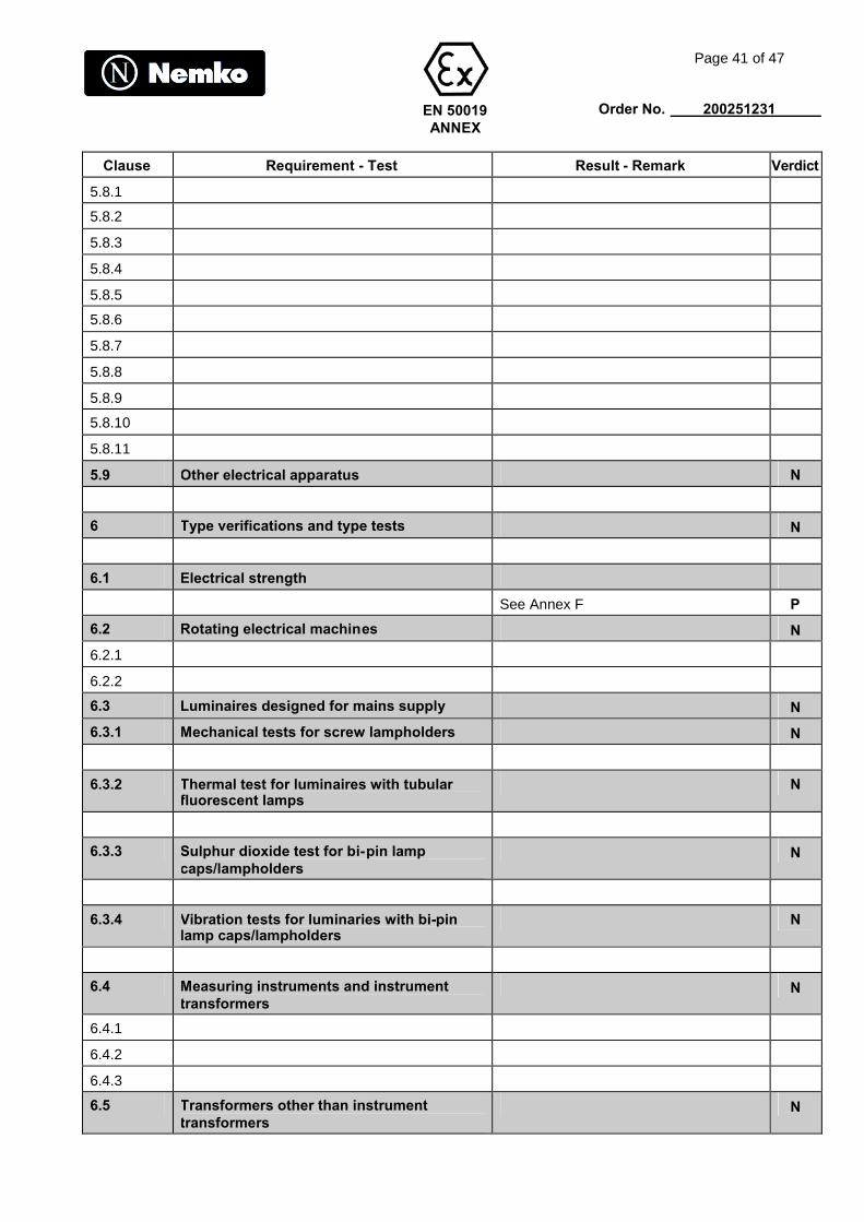
5.9 Other electrical apparatus N
6 Type verifications and type tests N
6.1 Electrical strength
See Annex F P
6.2 Rotating electrical machines N
6.2.1
6.2.2
6.3 Luminaires designed for mains supply N
6.3.1 Mechanical tests for screw lampholders N
6.3.2 Thermal test for luminaires with tubularfluorescent lamps
N
6.3.3 Sulphur dioxide test for bi-pin lampcaps/lampholders
N
6.3.4 Vibration tests for luminaries with bi-pinlamp caps/lampholders
N
6.4 Measuring instruments and instrumenttransformers
N
6.4.1
6.4.2
6.4.3
6.5 Transformers other than instrumenttransformers
N
EN 50019ANNEX
Page 42 of 47
Order No. 200251231
Clause Requirement - Test Result - Remark Verdict
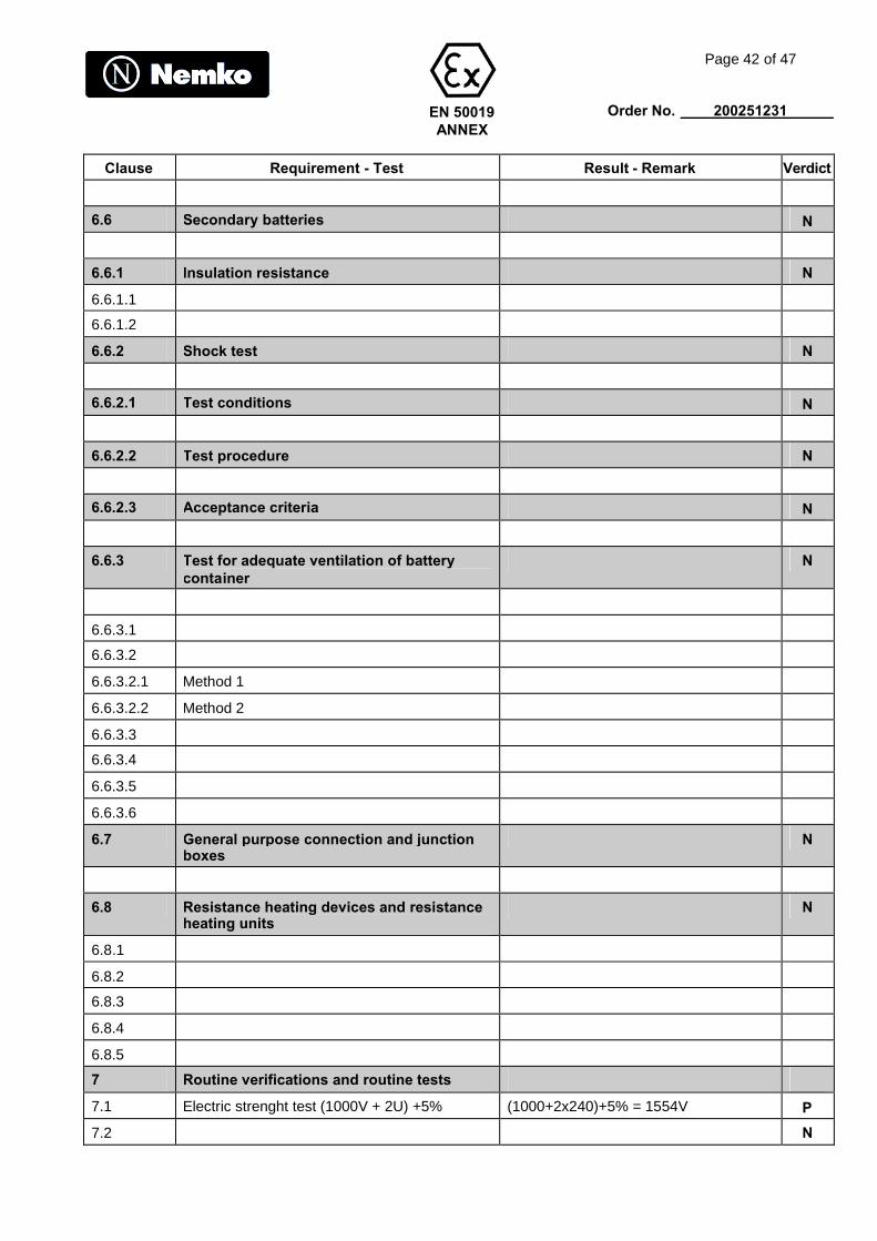
6.6 Secondary batteries N
6.6.1 Insulation resistance N
6.6.1.1
6.6.1.2
6.6.2 Shock test N
6.6.2.1 Test conditions N
6.6.2.2 Test procedure N
6.6.2.3 Acceptance criteria N
6.6.3 Test for adequate ventilation of batterycontainer
N
6.6.3.1
6.6.3.2
6.6.3.2.1 Method 1
6.6.3.2.2 Method 2
6.6.3.3
6.6.3.4
6.6.3.5
6.6.3.6
6.7 General purpose connection and junctionboxes
N
6.8 Resistance heating devices and resistanceheating units
N
6.8.1
6.8.2
6.8.3
6.8.4
6.8.5
7 Routine verifications and routine tests
7.1 Electric strenght test (1000V + 2U) +5% (1000+2x240)+5% = 1554V P
7.2 N
EN 50019ANNEX
Page 43 of 47
Order No. 200251231
Clause Requirement - Test Result - Remark Verdict
7.3 N
8 Marking
8.1 a) rated voltagerated currentnt and/or power
240V10, 16, 24, 30, 50W/m
P
8.2 N
8.2.1 N
8.2.3 N
ANNEX B
Lampholders and lamp caps for luminairesdesigned for mains supply
B.1 Screw lampholders and screw lamp caps
B.1.1 N
B.1.2 N
B.1.3 N
B.1.4 N
B.2 Other lampholders and lamp caps
B.2.1 N
B.2.2 N
B.3 Lampholders and lamp caps for tubularfluorescent lamps
B.3.1 N
B.3.2 N
B.3.2.1 N
B.3.2.2 N
B.3.2.3 N
B.3.2.4 N
B.3.2.5 N
B.3.2.6 N
B.3.2.7 N
B.3.2.8 N
B.4 Requirements for current transfer
B.4.1 N
B.4.2 N
Annex E
Cage motors- Methods of test and ofcalculation
E.1 N
E.2 N

EN 50019ANNEX
Page 44 of 47
Order No. 200251231
Clause Requirement - Test Result - Remark Verdict
E.3 N
E.3.1 N
E.3.2 N
E.3.3 N
E.3.4 N
E.3.5 N
E.4 N
E.4.1 N
E.4.2 N
E.5 N
E.6 N
E.7 N
ANNEX F
Type tests for specific forms of resistanceheating device and/or resistance heatingunit
F.1 Resistance heating devices or unitssubjected to mechanical stresses
Resistance heating devices or units which maybe subjected to mechanical stress for example,by crushing or bending during installation shallbe submitted to the following crushing and lowtemperature bend test.
P
F.1.1 Crushing test
Placed on rigid flat steel support
Crushing force: 1500NDuration: 30sSteel rod: 6mm
Followed by voltage test acc. to 6.8.2a) and b)
a) R.M.S voltage (500 +2U1): VDuration: 60s
No breakdown
b) D.C voltage 500VInsulation resistance >1,5M.km
980V
No breakdown occurred
SRL10-2CR 15M.kmSRL30-2CT 9M.kmSRL10-2CT 15M.kmSRL30-2CR 10M.kmSRL50-2CR 100M.km
P

EN 50019ANNEX
Page 45 of 47
Order No. 200251231
Clause Requirement - Test Result - Remark Verdict
F.1.2 Low temperature bend test
Sample placed in refrigerator. Placed inapparatus for 4h
Temperature CMadrel diameter mm
Followed by voltage test acc. to 6.8.2a) and b)
a) R.M.S voltage (500 +2U1): VDuration: 60s
No breakdown
b) D.C voltage 500VInsulation resistance >1,5M.km
-40CSRL10-30 35mmSRL50 50mm
980V
No breakdown
SRL10-2CR 20M.kmSRL30-2CT 8M.kmSRL10-2CT 18M.kmSRL30-2CR 9M.kmSRL50-2CR 150M.km
P
F.2 Resistance heating devices or unitsintended for immersion
Sample or part of sample immersed in tapwater
Duration of immersion 14x24h
Followed by voltage test acc. to 6.8.2a) and b)
a) R.M.S voltage (500 +2U1): VDuration: 60s
No breakdown
b) D.C voltage 500VInsulation resistance >M
N
F.3 Resistance heating devices or units havinghygroscopic insulating material
Sample placed in humidity chamber
Duration: 14x24hTemperature: 802CHumidity: >90% R.H
Followed by voltage test acc. to 6.8.2a) and b),omitting the water immersion.
a) R.M.S voltage (500 +2U1): VDuration: 60s
No breakdown
b) D.C voltage 500VInsulation resistance >1,5M.km
980V
No breakdown
SRL10-2CR 18M.kmSRL30-2CT 10M.kmSRL10-2CT 16M.kmSRL30-2CR 8M.kmSRL50-2CR 120M.km
P

EN 50019ANNEX
Page 46 of 47
Order No. 200251231
Clause Requirement - Test Result - Remark Verdict
F.4 Verification of limiting temperature
P
F.4.1 Resistance heating unit protected by aprotective system according to 5.8.9
N
F.4.1.1 Protective system sensing the temperature
N
F.4.1.2 Protective system sensing the temperatureand at least one other parameter
N
F.4.1.3 Protective system sensing (a) parameter(s)other than the temperature
N
F.4.2 Resistance heating unit of stabilized design
N
F.4.3 Heating device with self-limitingcharacteristic
Sample being close-coiled inside a close-fittingbox of thermally insulating material.
Sample length: 3–4mVoltage (rated voltage +10%) VTemperature: -203C
Maximum temperature: C
264V
SRL10-2CR 75CSRL30-2CT 75CSRL10-2CT 75CSRL30-2CR 87CSRL50-2CR 101C
P
This test was also carried out using atest voltage of 277V
Then
SRL30-2CR 88CSRL50-2CR 102C
P
EN 50019ANNEX
Page 47 of 47
Order No. 200251231
Description of the apparatus: