test plan for rf performance evaluation of wi-fi mobile ... · wi-fi alliance 10900-b stonelake...
TRANSCRIPT

Test Plan for RF Performance Evaluation of Wi-Fi Mobile Converged Devices
Version 2.0.3
September 2016
© 2016 CTIA - The Wireless Association®. All rights reserved. CTIA hereby grants to CTIA Authorized Testing Laboratories (CATLs), and only to CATLs, a limited, non-transferable license to use this Test Plan for the sole purpose of testing wireless devices for the CTIA Certification Program, and to reproduce this Test Plan for internal use only. Any other use of this Test Plan must be authorized in writing by CTIA. Any reproduction or transmission of all or part of this Test Plan, in any form or by any means, electronic or mechanical, including photocopying, recording, or via any information storage and retrieval system, without the prior written permission of CTIA, is unauthorized and strictly prohibited. Any reproduction of this Test Plan shall display the notice: "Copyright by CTIA. All rights reserved."

Certification Program Test Plan
September 2016 2 Version 2.0.3
CTIA - The Wireless Association 1400 16th Street, NW Suite 600 Washington, DC 20036 Phone: 1.202.785.0081 Email: [email protected]
Wi-Fi Alliance 10900-B Stonelake Boulevard Suite 126 Austin, TX 78759 Phone: 1.512.498.9434 Email: [email protected]

Certification Program Test Plan
September 2016 3 Version 2.0.3
Acknowledgements This test plan was created by the wireless industry with input from the following companies and their representatives:
Company, Representative Company, Representative
AT&T, Scott Prather, Sungmi Choi, Jason Brown
NEC, Sanjay Wadhwa
Azimuth Systems, Charles Wright Nokia Corp., Alan Ewing, Steve Wilhoff, Randy Leenerts, Karthik Babu Adappa Laxmi, Kevin Li
Blackberry, Michael Montemurro Philips Semiconductor, Steve Shearer
CETECOM, Inc, Lothar Schmidt Rohde & Schwarz, Lisa Ward, Christoph Gagern, Thorsten Hertel, Alex Tkatch
Cisco, Sam Kim, Jae il Choi Samsung, Chirag Panchal, James White, Kwangmin Choi, Usman Aurakzai
DSP Group, Graham Smith Satimo, John Estrada, Kim Rutkowski, Alessandro Scannavini
ETS-Lindgren, Michael Foegelle, Edwin Mendivil
SGS, Jason Bartosch, Nicky (Ho) You, Peter Liao
Fitbit, Kevin Li Spirent Communications, Ronald Borsato
Intel, Hassan Yaghoobi Sporton, Elvis Yen, Lorien Chang
Ixia, Larry Green Sprint, Alex Tkatch
Keysight, Moray Rumney Telecommunications Metrology Center of China Ministry of Information Industry, Heather Gao
Microsoft, Kevin Li Underwriters Laboratories, Ekta Budhbhatti
Motorola Mobility, Paul Moller, Istvan Szini
Wi-Fi Alliance, Patrick Green, Steve Shearer
Multi-Tech, Jody Lanes

Certification Program Test Plan
September 2016 4 Version 2.0.3
Table of Contents Section 1 Introduction ................................................................................................................... 6
1.1 Background .................................................................................................................. 6 1.2 Scope ........................................................................................................................... 6 1.3 Purpose ........................................................................................................................ 6 1.4 References ................................................................................................................... 6 1.5 Test Nomenclature Overview ........................................................................................ 7
1.5.1 Conducted RF Tests ..................................................................................................7 1.5.2 Radiated RF Tests......................................................................................................7 1.5.3 Desensitization Tests .................................................................................................7
1.6 Baseline Methodology ................................................................................................... 7 1.6.1 Measurement Techniques and Test Methodologies .............................................7 1.6.2 Measurement Uncertainty .........................................................................................7 1.6.3 Minimum Measurement Distance .............................................................................7 1.6.4 Quiet Zone Test Frequencies ...................................................................................8
1.7 Form Factor Submission for Self-contained Wi-Fi/Mobile Modules................................. 8 1.8 List of Acronyms ........................................................................................................... 9
Section 2 Test Conditions and Device Configuration ................................................................... 10 2.1 Cellular and Wi-Fi Modes ............................................................................................ 10 2.2 Wi-Fi Mode ................................................................................................................. 10
Section 3 Conducted Measurements........................................................................................ 12 3.1 Wi-Fi Conducted RF Power Output and Receiver Sensitivity Tests .............................. 12
3.1.1 Test Purpose ............................................................................................................ 12 3.1.2 Test Setup................................................................................................................. 12 3.1.3 Measurement Frequencies and Data Rates for Conducted tests .................... 12 3.1.4 Test Procedure for Output Power Level ............................................................... 13 3.1.5 Test Procedure for Receiver Sensitivity ............................................................... 14 3.1.6 Results ...................................................................................................................... 15
Section 4 Radiated Measurements ........................................................................................... 16 4.1 Wi-Fi Total Radiated Measurements (TRP/TIS) ........................................................... 16
4.1.1 Test Purpose ............................................................................................................ 16 4.1.2 Test Setup................................................................................................................. 16 4.1.3 Measurement Frequencies for Radiated Tests ................................................... 17 4.1.4 Test Procedure for Total Radiated Power Measurement .................................. 18 4.1.5 Test Procedure for Total Isotropic Sensitivity Measurement............................. 18 4.1.6 TRP Data Rates ....................................................................................................... 19 4.1.7 TIS Data Rates......................................................................................................... 19 4.1.8 Results ...................................................................................................................... 19
4.2 Wi-Fi Desense Measurements with Cellular Transmitter ON ........................................ 20 4.2.1 Test Purpose ............................................................................................................ 20 4.2.2 Test Setup................................................................................................................. 20 4.2.3 Test Procedures for Wi-Fi Radio Desensitization ............................................... 21
Certification Program Test Plan
September 2016 5 Version 2.0.3
4.2.4 Wi-Fi Radio Desensitization by Closest Cellular Uplink Frequency ................. 21 4.2.5 Wi-Fi Radio Desensitization by Cellular Radio Uplink Harmonics ................... 24 4.2.6 Results ...................................................................................................................... 28
4.3 Cellular Desense Measurements with Wi-Fi transmitter ON ......................................... 28 4.3.1 Test Purpose ............................................................................................................ 28 4.3.2 Test Setup................................................................................................................. 28 4.3.3 Test Procedure for GSM, CDMA and UMTS RATs listed in the CTIA Test Plan 29
4.3.4 Test Procedure for RATs ........................................................................................ 29 4.3.5 Test Procedure for all LTE cases .......................................................................... 30 4.3.6 Wi-Fi Frequency....................................................................................................... 30 4.3.7 Error Rate Measure ................................................................................................. 30 4.3.8 Results ...................................................................................................................... 31
Appendix A Summary Test Report .................................................................................................... 32 A.1. Wi-Fi Conducted Tests ............................................................................................. 33 A.2. Total Radiated Power (TRP)and Total Isotropic Sensitivity (TIS) for 2.4 GHz 802.11b, 802.11g and 802.11n ............................................................................................... 34 A.3. Total Radiated Power (TRP) and Total Isotropic Sensitivity (TIS) for 802.11a and 802.11n ................................................................................................................................... 35 A.4. Wi-Fi Desense Measurements (with cellular transmitter on) .................................. 37 A.5. Cellular Desense Measurements (with Wi-Fi transmitter on) .................................. 37
Appendix B Handheld Device Testing Configurations ..................................................................... 40 Appendix C Radio Access Technologies that Require Testing, but are not Normative in the CTIA
Test Plan ................................................................................................................................... 41 C.1 TD-SCDMA ................................................................................................................ 41 C.2 LTE TDD .................................................................................................................... 41
Appendix D Notebook and Tablet Requirements .............................................................................. 42 D.1 Parent/Child Relationships .......................................................................................... 42 D.2 Parent/Child Antenna Subsystem Considerations ........................................................ 42 D.3 Test Configurations and Setup Procedures ................................................................. 42
Appendix E Wi-Fi-LTE Emulator Test Equipment Notes when Testing EUTs that Support LTE Band 40 or 41 (Informative) ...................................................................................................... 44
Appendix F Table of Wi-Fi Radio channels interfered by Cellular Radio Harmonics ...................... 46 Appendix G Change History ............................................................................................................... 55

Certification Program Test Plan
September 2016 6 Version 2.0.3
Section 1 Introduction
1.1 Background
Increasingly the wireless market is seeing converged devices that incorporate both cellular and wireless local area network (WLAN or Wi-Fi) functionality. Due to the many potential applications and deployment scenarios that converged devices may ultimately function in, operators and device vendors are interested in a uniform and standard way for profiling the RF performance of the devices and associated test methodology. With this standard approach, equipment designers, system operators, and RF engineers have the flexibility to determine their own appropriate RF performance criteria based on their engineering assessments and can easily identify equipment that is suitable for each deployment and application.
1.2 Scope
This test document specifies test methodologies and performance criteria for the RF performance evaluation of Wi-Fi mobile converged devices. The scope of testing includes Handheld, self-contained Wi-Fi/Mobile Module, Access Point, Notebook and Tablet devices that support IEEE 802.11a, 802.11b,802.11g or 802.11n [2] as well as cellular technologies. Support for IEEE 802.11 standards must be confirmed through Wi-Fi Alliance baseline certification—that is, devices tested using this test plan must first be Wi-Fi CERTIFIED for IEEE 802.11a, 802.11b, 802.11g or 802.11n [4]. Cellular technologies include GSM, CDMA, UMTS (WCDMA), LTE and TD-SCDMA.
1.3 Purpose
The purpose of this document is to define the test methodology for the RF testing of Wi-Fi mobile converged devices and to specify the test conditions for each test case. The testing covers client devices and access points and specifies conducted as well as radiated tests.
1.4 References
[1] “Test Plan for Wireless Device Over-the-Air Performance/Method of Measurement for Radiated RF Power and Receiver Performance”, latest revision,
CTIA http://www.ctia.org/policy-initiatives/wireless-device-certification/certification-test-plans
[2] “IEEE Std. 802.11-2012 IEEE Standard for Information technology--Telecommunications and information exchange between systems Local and metropolitan area networks--Specific requirements Part 11: Wireless LAN Medium Access Control (MAC) and Physical Layer (PHY) Specifications”
IEEE http://standards.ieee.org/about/get/802/802.11.html
[3] “User Equipment (UE) / Mobile Station (MS) Over The Air (OTA) antenna performance; Conformance testing (3GPP TS 34.114)”, Latest Revision,
3GPP http://www.3gpp.org/DynaReport/34114.htm
[4] Check the product’s Wi-Fi Certificate at:
http://certifications.www.wi-fi.org/wbcs_certified_products.php?lang=en
[5] RFC 792 “Internet Control Message Protocol”, IETF, September 1981
https://tools.ietf.org/html/rfc792

Certification Program Test Plan
September 2016 7 Version 2.0.3
[6] RFC 1122 “Requirements for Internet Hosts – Communication Layers”, IETF, October 1989,
https://tools.ietf.org/html/rfc1122
1.5 Test Nomenclature Overview
1.5.1 Conducted RF Tests Conducted tests are those RF Tests where the test equipment is connected to the antenna connector of the device under test by co-axial cables. These tests are formulated to measure basic RF performance such as sensitivity and transmit power.
1.5.2 Radiated RF Tests Radiated tests are those RF Tests that are carried out in a test environment which meets the requirements of the CTIA Test Plan [1]. These include Wi-Fi radiated Tx Power (TRP), Wi-Fi radiated Receive Sensitivity (TIS), Radiated Receive Sensitivity of Wi-Fi with cellular active, and Radiated Receive Sensitivity of the cellular radio(s) with Wi-Fi active.
1.5.3 Desensitization Tests Desensitization tests measure the impact that the cellular radio, when transmitting, has upon Wi-Fi reception and visa-versa. These tests are performed as radiated tests according to Device Testing Configurations.
1.6 Baseline Methodology
1.6.1 Measurement Techniques and Test Methodologies TRP and TIS in cellular mode are defined in both the CTIA Test Plan for Wireless Device Over-the-Air Performance [1] and User Equipment (UE) / Mobile Station (MS) Over The Air (OTA) antenna performance; Conformance testing (3GPP TS 34.114) [3].
This document relies on the measurement techniques and methodologies within the CTIA Test Plan [1] for Wireless Device Over-the-Air Performance (referred to in this document hereafter as “CTIA Test Plan”) developed specifically for the purposes of measurement of radiated transmit power and sensitivity. The techniques specified in the CTIA Test Plan shall be used as the baseline test methodologies for all tests in here, unless otherwise stated. This document contains information to expand the CTIA Test Plan for use with 802.11 a, b, g and n devices. These sections are meant to clarify for the user how the CTIA Test Plan can be utilized for Wi-Fi enabled converged devices.
1.6.2 Measurement Uncertainty Refer to CTIA Test Plan Section 7 for the uncertainty budget tables for TRP and TIS. The lab shall report their estimated measurement uncertainty for both the 2.4 and 5 GHz bands. However, the criteria in Section 7.5 [1] only apply to the 2.4 GHz band.
1.6.3 Minimum Measurement Distance This section describes the minimum measurement distance, R, which the Far-Field test site shall provide. The measurement distance is defined as the distance from the center of rotation of the EUT to the phase center (alternatively, if not accurately known, the nearest point) of the Measurement Antenna.
For Cellular minimum measurement distance, refer to CTIA Test Plan Section 3.1. [1] For Wi-Fi 2.4 GHz band, the minimum measurement distance specification specified for Band 41 shall be used. For Wi-Fi 5 GHz band, the minimum measurement distance is FFS; refer to Sections G.7.4 and G.19.1 of the CTIA Test Plan for more information. [1]

Certification Program Test Plan
September 2016 8 Version 2.0.3
1.6.4 Quiet Zone Test Frequencies Quiet zone test frequencies shall be measured for the following Wi-Fi bands.
1. ISM-band: 2450 MHz ± 1MHz (sleeve dipole and loop probe antenna)
2. U-NII-band: 5500 MHz ± 1MHz (sleeve dipole and loop probe antenna)
1.7 Form Factor Submission for Self-contained Wi-Fi/Mobile Modules
The following two cases are considered regarding the antenna subsystem options and required form factor submission for self-contained Wi-Fi/Mobile modules. Also, please refer to Appendix D for Notebook and Tablet.
The test results shall include a description and diagram or photograph of the test conditions used for the device under test.
CASE 1 with Internal Antenna: If the EUT is a self-contained Wi-Fi/Mobile Module with internal antennas, such as a PC Card, then the vendor may choose one of the following options:
1. Supply the EUT together with one of its intended host platforms, e.g., a laptop computer. In this case, the combination shall then be placed on the turntable and the results sheet shall clearly state the combination that was used in the measurements.
2. Test the Module, on its own, mounted in a holder that orientates the module in the position that represents its normal use. In this case the results sheet shall clearly state that the test did not include a host device.
3. Carry out both tests as above. This is the preferred method, but not mandatory.
CASE 2 without Internal Antenna: If the EUT is a self-contained Wi-Fi/Mobile Module without internal antennas, such as an mPCI Card, then the vendor must supply the complete device, which includes the antennas, for testing. No individual module testing is acceptable.

Certification Program Test Plan
September 2016 9 Version 2.0.3
1.8 List of Acronyms
Acronym Definition
ACK Acknowledge
APSD Automatic Power Save Delivery
CDMA Code Division Multiple Access
EIS Effective Isotropic Sensitivity
EUT Equipment Under Test
GSM Global System for Mobile communication
LAN Local Area Network
LTE Long Term Evolution
MIMO Multiple Input Multiple Output
PER Packet Error Rate
RAT Radio Access Technology
Rx Receive
TD-SCDMA Time Division Synchronous Code Division Multiple Access
TIS Total Isotropic Sensitivity
TRP Total Radiated Power
Tx Transmit
UMTS Universal Mobile Telecommunications System
UTRA-FDD UMTS Terrestrial Radio Access - Frequency Division Duplexing
UTRA-TDD UMTS Terrestrial Radio Access - Time Division Duplexing
WCDMA Wideband Code Division Multiple Access
WLAN Wireless Local Area Network
WWAN Wireless Wide Area Network
Certification Program Test Plan
September 2016 10 Version 2.0.3
Section 2 Test Conditions and Device Configuration
2.1 Cellular and Wi-Fi Modes
The test methodology requires the device be placed in a standard operational mode. This includes all sensors in the device as well as proximity sensors. If it becomes evident that EUT thermal protection and/or adaptive power control mechanisms are preventing Wi-Fi and cellular transmitters from maintaining full output power during the course of testing, the test lab shall work with the OEM to identify a suitable mitigation method. Although recognizing that the use of special test modes would enable more simplified testing and the use of formal test equipment, the test methodology proposed in this document allows the testing of any Wi-Fi mobile device in a mode that is as close as possible to its native operation. However, the methodology does require certain specific behavior of the device so that the test can be executed. EUT vendors are required to supply instructions for the lab to configure the devices as specified in this test plan.
All Radiated tests shall be made according to configurations specified in Device Testing Configurations with the device oriented as specified in Section A.1.1 or A.1.5 (as appropriate) of the CTIA Test Plan [1] as applied to the Wi-Fi mode being tested.
Note that depending on the communication tester and device capabilities, it may be necessary to set or disable the regulatory domain (WLAN Country Code and/or Cellular MCC) setting on the WLAN tester and/or cellular base station simulator in order to test specific channel combinations. Care should be taken to present the specific regulatory domain information to the EUT in an isolated environment so that the regulatory domain information is not obtained from any external Wi-Fi access point and/or cellular network in the country where the test is being executed. The lab should seek guidance from the EUT vendor to ensure that all test channels supported by the EUT are tested.
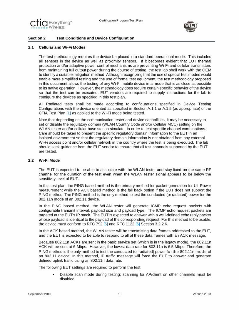
2.2 Wi-Fi Mode
The EUT is expected to be able to associate with the WLAN tester and stay fixed on the same RF channel for the duration of the test even when the WLAN tester signal appears to be below the sensitivity level of EUT.
In this test plan, the PING based method is the primary method for packet generation for UL Power measurement while the ACK based method is the fall back option if the EUT does not support the PING method. The PING method is the only method to test the conducted (or radiated) power for the 802.11n mode of an 802.11 device.
In the PING based method, the WLAN tester will generate ICMP echo request packets with configurable transmit interval, payload size and payload type. The ICMP echo request packets are targeted at the EUT's IP stack. The EUT is expected to answer with a well-defined echo reply packet whose payload is identical to the payload of the corresponding request. For this method to be usable, the device must conform to RFC 792 [5] and RFC 1122 [6] Section 3.2.2.6.
In the ACK based method, the WLAN tester will be transmitting data frames addressed to the EUT, and the EUT is expected to be able to respond to all of these data frames with an ACK message.
Because 802.11n ACKs are sent in the basic service set (which is in the legacy mode), the 802.11n ACK will be sent at 6 Mbps. However, the lowest data rate for 802.11n is 6.5 Mbps. Therefore, the PING method is the only method to test the conducted (or radiated) power for the 802.11n mode of an 802.11 device. In this method, IP traffic message will force the EUT to answer and generate defined uplink traffic using an 802.11n data rate.
The following EUT settings are required to perform the test:
• Disable scan mode during testing; scanning for AP/client on other channels must be disabled,

Certification Program Test Plan
September 2016 11 Version 2.0.3
• If applicable, disable Power Save Mode (Note that the WLAN tester will not support WMM APSD),
• If applicable, disable the Bluetooth radio during tests,
• Except for the desense testing, the cellular transmitter in the EUT shall be inactive.
Radiated testing shall be performed on an unmodified device using all active antennas. Conducted tests shall be performed on each antenna port with the other antenna port(s) properly terminated. If necessary, an equivalent device maybe modified to provide conducted access to each antenna port.
For all Wi-Fi RATs, including 802.11n, 20 MHz channels are used. 802.11n should be configured for a long guard interval.

Certification Program Test Plan
September 2016 12 Version 2.0.3
Section 3 Conducted Measurements
3.1 Wi-Fi Conducted RF Power Output and Receiver Sensitivity Tests
3.1.1 Test Purpose The purpose of this test is to measure the output power level and receiver sensitivity of the Wi-Fi transceiver in the device in the conducted mode.
3.1.2 Test Setup The basic test setup is shown in Figure 3.1-1.
FIGURE 3.1-1 BLOCK DIAGRAM FOR WI-FI CONDUCTED MEASUREMENT
WLAN Tester
Control PC
EUT
Please note that Figure 3.1-1 is intentionally generalized to maximize test equipment design flexibility. A WLAN tester may include receiver and access point capability sub modules as well as internally implemented attenuators to control transmit and receive power to and from EUT.
The EUT shall be provided to the Test Laboratory with the facility to connect directly to the RF test equipment. This may be via an existing antenna connector, or it may be a carefully modified unit to allow such connection. In the latter case, it is the responsibility of the supplier of the EUT to ensure that the connection is present and suitable.
It is recommended that the conducted measurements be performed inside a shielded environment.
A reference measurement shall be made in order to account for the attenuation of the cable used for connecting the EUT and WLAN tester.
For more information about possible test setup configurations and details, refer to Appendix A of the CTIA Test Plan for setup illustrations. [1]
3.1.3 Measurement Frequencies and Data Rates for Conducted tests The measurements shall be performed on the lowest, middle1 and highest channels supported by the device, in each of the 2.4 GHz and 5 GHz bands, at all data rates specified in Table 3.1-1 and Table 3.1-2.
1 For 5 GHz bands, refer to Table 4-1 for the middle channel number for each sub band.
Certification Program Test Plan
September 2016 13 Version 2.0.3
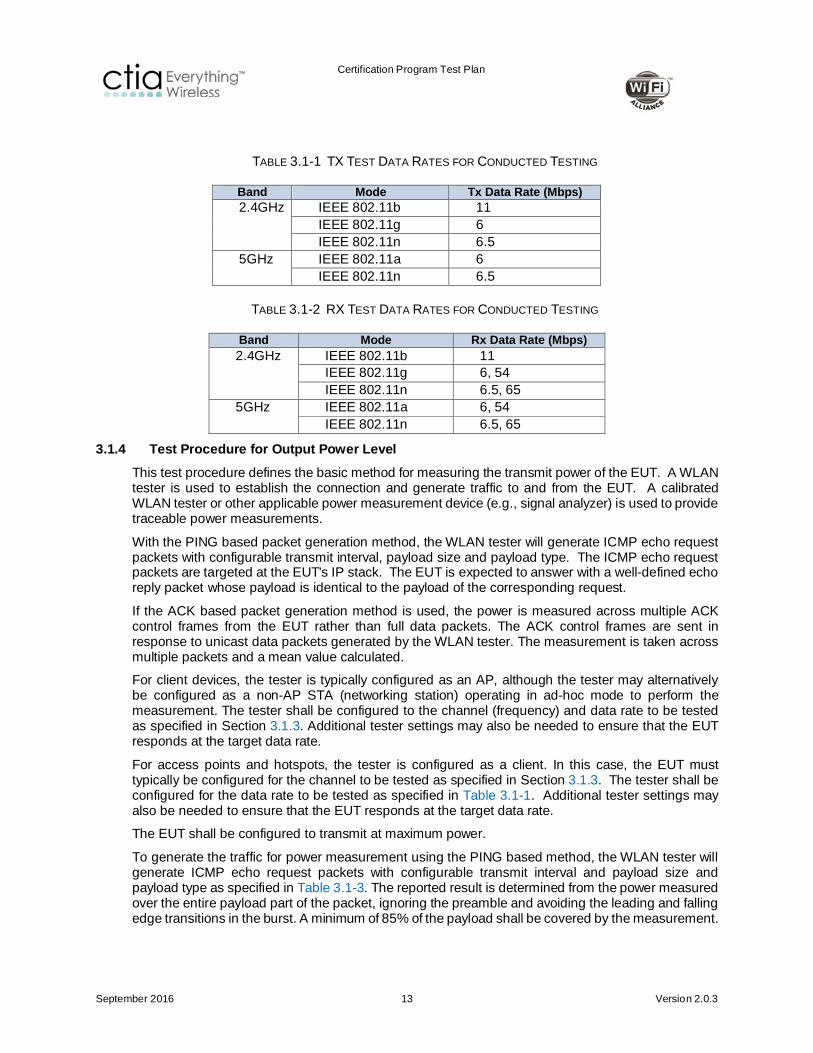
TABLE 3.1-1 TX TEST DATA RATES FOR CONDUCTED TESTING
Band Mode Tx Data Rate (Mbps) 2.4GHz IEEE 802.11b 11
IEEE 802.11g 6 IEEE 802.11n 6.5
5GHz IEEE 802.11a 6 IEEE 802.11n 6.5
TABLE 3.1-2 RX TEST DATA RATES FOR CONDUCTED TESTING
Band Mode Rx Data Rate (Mbps) 2.4GHz IEEE 802.11b 11
IEEE 802.11g 6, 54 IEEE 802.11n 6.5, 65
5GHz IEEE 802.11a 6, 54 IEEE 802.11n 6.5, 65
3.1.4 Test Procedure for Output Power Level This test procedure defines the basic method for measuring the transmit power of the EUT. A WLAN tester is used to establish the connection and generate traffic to and from the EUT. A calibrated WLAN tester or other applicable power measurement device (e.g., signal analyzer) is used to provide traceable power measurements.
With the PING based packet generation method, the WLAN tester will generate ICMP echo request packets with configurable transmit interval, payload size and payload type. The ICMP echo request packets are targeted at the EUT's IP stack. The EUT is expected to answer with a well-defined echo reply packet whose payload is identical to the payload of the corresponding request.
If the ACK based packet generation method is used, the power is measured across multiple ACK control frames from the EUT rather than full data packets. The ACK control frames are sent in response to unicast data packets generated by the WLAN tester. The measurement is taken across multiple packets and a mean value calculated.
For client devices, the tester is typically configured as an AP, although the tester may alternatively be configured as a non-AP STA (networking station) operating in ad-hoc mode to perform the measurement. The tester shall be configured to the channel (frequency) and data rate to be tested as specified in Section 3.1.3. Additional tester settings may also be needed to ensure that the EUT responds at the target data rate.
For access points and hotspots, the tester is configured as a client. In this case, the EUT must typically be configured for the channel to be tested as specified in Section 3.1.3. The tester shall be configured for the data rate to be tested as specified in Table 3.1-1. Additional tester settings may also be needed to ensure that the EUT responds at the target data rate.
The EUT shall be configured to transmit at maximum power.
To generate the traffic for power measurement using the PING based method, the WLAN tester will generate ICMP echo request packets with configurable transmit interval and payload size and payload type as specified in Table 3.1-3. The reported result is determined from the power measured over the entire payload part of the packet, ignoring the preamble and avoiding the leading and falling edge transitions in the burst. A minimum of 85% of the payload shall be covered by the measurement.
Certification Program Test Plan
September 2016 14 Version 2.0.3
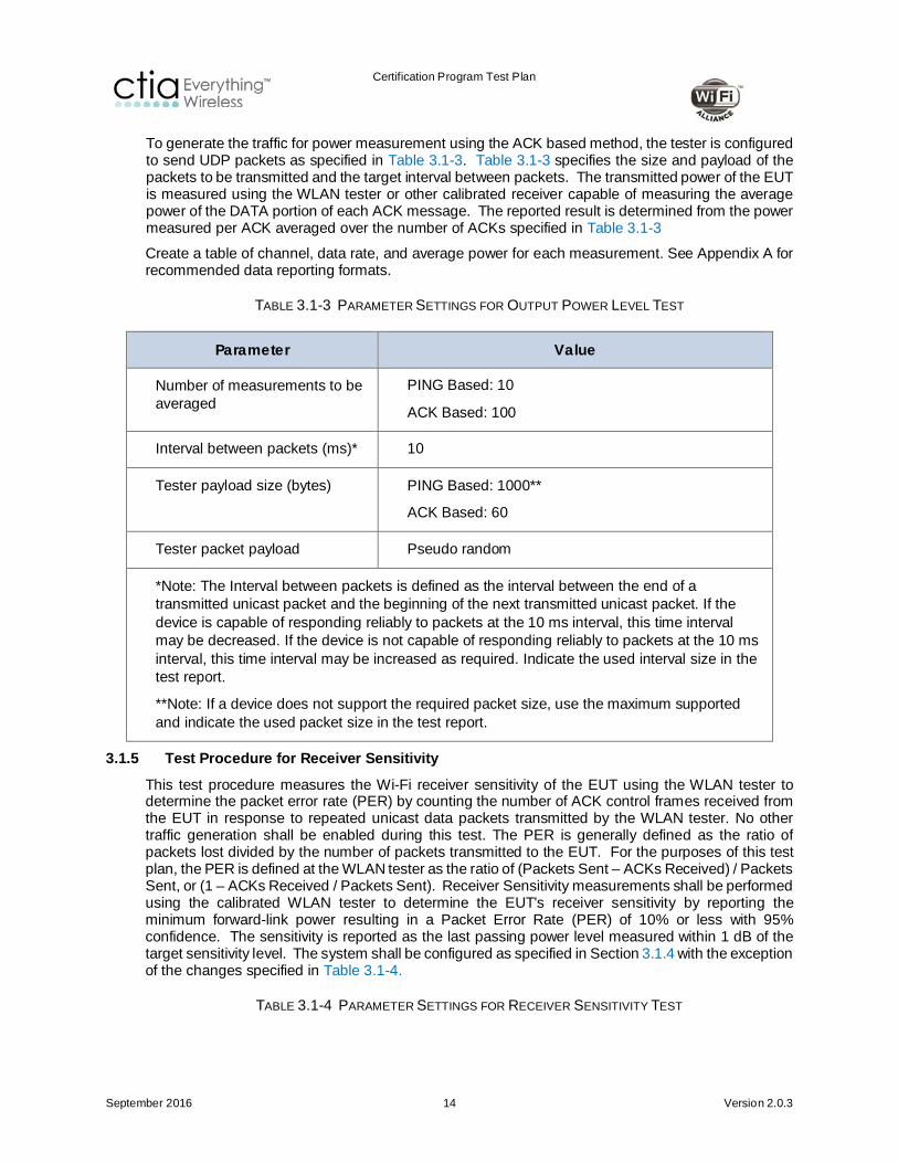
To generate the traffic for power measurement using the ACK based method, the tester is configured to send UDP packets as specified in Table 3.1-3. Table 3.1-3 specifies the size and payload of the packets to be transmitted and the target interval between packets. The transmitted power of the EUT is measured using the WLAN tester or other calibrated receiver capable of measuring the average power of the DATA portion of each ACK message. The reported result is determined from the power measured per ACK averaged over the number of ACKs specified in Table 3.1-3
Create a table of channel, data rate, and average power for each measurement. See Appendix A for recommended data reporting formats.
TABLE 3.1-3 PARAMETER SETTINGS FOR OUTPUT POWER LEVEL TEST
Parameter Value
Number of measurements to be averaged
PING Based: 10
ACK Based: 100
Interval between packets (ms)* 10
Tester payload size (bytes) PING Based: 1000**
ACK Based: 60
Tester packet payload Pseudo random
*Note: The Interval between packets is defined as the interval between the end of a transmitted unicast packet and the beginning of the next transmitted unicast packet. If the device is capable of responding reliably to packets at the 10 ms interval, this time interval may be decreased. If the device is not capable of responding reliably to packets at the 10 ms interval, this time interval may be increased as required. Indicate the used interval size in the test report.
**Note: If a device does not support the required packet size, use the maximum supported and indicate the used packet size in the test report.
3.1.5 Test Procedure for Receiver Sensitivity This test procedure measures the Wi-Fi receiver sensitivity of the EUT using the WLAN tester to determine the packet error rate (PER) by counting the number of ACK control frames received from the EUT in response to repeated unicast data packets transmitted by the WLAN tester. No other traffic generation shall be enabled during this test. The PER is generally defined as the ratio of packets lost divided by the number of packets transmitted to the EUT. For the purposes of this test plan, the PER is defined at the WLAN tester as the ratio of (Packets Sent – ACKs Received) / Packets Sent, or (1 – ACKs Received / Packets Sent). Receiver Sensitivity measurements shall be performed using the calibrated WLAN tester to determine the EUT's receiver sensitivity by reporting the minimum forward-link power resulting in a Packet Error Rate (PER) of 10% or less with 95% confidence. The sensitivity is reported as the last passing power level measured within 1 dB of the target sensitivity level. The system shall be configured as specified in Section 3.1.4 with the exception of the changes specified in Table 3.1-4.
TABLE 3.1-4 PARAMETER SETTINGS FOR RECEIVER SENSITIVITY TEST

Certification Program Test Plan
September 2016 15 Version 2.0.3
Parameter Value
Interval between packets (ms)* 1
Packet size (bytes)
802.11a/b/g/n 1000**
Min number of packets 1000
*Note: If the device is not capable of responding reliably to packets at the 1 ms interval, this time interval may be increased as required; indicate the used interval size in the test report.
**Note: If a device does not support the required packet size, use the maximum supported and indicate the used packet size in the test report.
3.1.6 Results Results shall be reported in dBm.
There are no Pass/Fail criteria. Refer to Appendix A for sample report templates.

Certification Program Test Plan
September 2016 16 Version 2.0.3
Section 4 Radiated Measurements
4.1 Wi-Fi Total Radiated Measurements (TRP/TIS)
4.1.1 Test Purpose The purpose of this test is to measure the Total Radiated Power and Total Isotropic Sensitivity of the Wi-Fi transceiver in the device.
4.1.2 Test Setup Typical system schematics for both TRP and TIS measurements are shown in the following figures. The configurations shown are only representative examples of test systems configuration. The figure below shows a configuration where both uplink and downlink communications are transmitted through the measurement antenna. This configuration does not support independent amplification of both signal paths if necessary.
FIGURE 4.1-1 SIMPLIFIED BLOCK DIAGRAM SHOWING A COMMON CONFIGURATION FOR TRP/TIS MEASUREMENT
WLAN Tester
Control PC
EUT
Anechoic Chamber
Measurement Antenna
Amplifier(optional) θ-pol
φ-pol
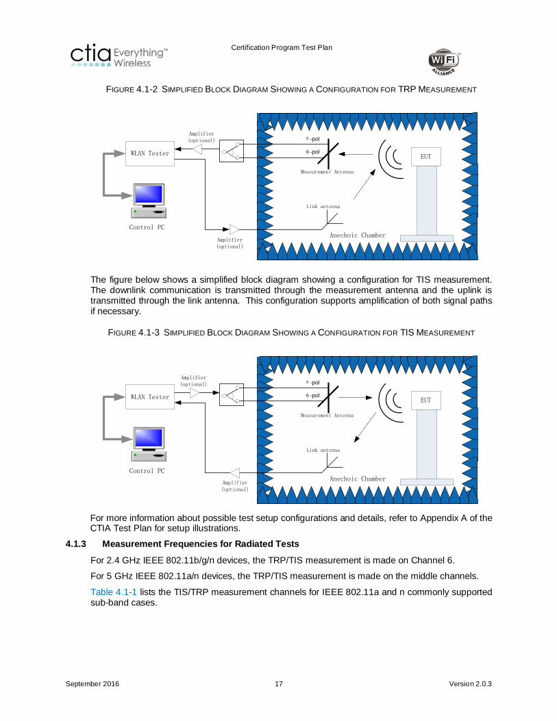
The figure below shows a simplified block diagram showing a configuration for TRP measurement. The uplink communication is transmitted through the measurement antenna and the downlink is transmitted through the link antenna. This configuration supports amplification of both signal paths if necessary.
Certification Program Test Plan
September 2016 17 Version 2.0.3
FIGURE 4.1-2 SIMPLIFIED BLOCK DIAGRAM SHOWING A CONFIGURATION FOR TRP MEASUREMENT
WLAN Tester
Control PC
EUT
Anechoic Chamber
Measurement Antenna
Link antenna
Amplifier(optional) θ-pol
φ-pol
Amplifier(optional)
The figure below shows a simplified block diagram showing a configuration for TIS measurement. The downlink communication is transmitted through the measurement antenna and the uplink is transmitted through the link antenna. This configuration supports amplification of both signal paths if necessary.
FIGURE 4.1-3 SIMPLIFIED BLOCK DIAGRAM SHOWING A CONFIGURATION FOR TIS MEASUREMENT
WLAN Tester
Control PC
EUT
Anechoic Chamber
Measurement Antenna
Link antenna
Amplifier(optional)
Amplifier(optional)
θ-pol
φ-pol
For more information about possible test setup configurations and details, refer to Appendix A of the CTIA Test Plan for setup illustrations.
4.1.3 Measurement Frequencies for Radiated Tests For 2.4 GHz IEEE 802.11b/g/n devices, the TRP/TIS measurement is made on Channel 6.
For 5 GHz IEEE 802.11a/n devices, the TRP/TIS measurement is made on the middle channels.
Table 4.1-1 lists the TIS/TRP measurement channels for IEEE 802.11a and n commonly supported sub-band cases.

Certification Program Test Plan
September 2016 18 Version 2.0.3
TABLE 4.1-1 TIS/TRP MEASUREMENT CHANNELS FOR IEEE 802.11A AND N SUPPORTED SUB-BANDS
Sub Band Channel Range TIS/TRP Channel
UNII Low Band 36 to 48 44
UNII Middle Band 52 to 64 60
ETSI European band 100 to 140 120
UNII Upper Band 149 to 161 157
USA 165 165
4.1.4 Test Procedure for Total Radiated Power Measurement This test procedure is primarily based on the TRP measurement procedure specified in the CTIA Test Plan [1]. For more details, please refer to the procedure specified in CTIA Test Plan Sections 2 and 5 for TRP measurement.
In order to obtain accurate results of radiated performance of Wi-Fi, it is necessary to perform a range reference measurement to account for the various factors affecting the measurement of these quantities. These factors include components like range length, path loss, gain of the receive antenna, cable losses, and so forth. Please refer to CTIA Test Plan [1] Section 4 for more details.
A calibrated WLAN tester capable of maintaining the connection over the air is required. The WLAN tester or other applicable power measurement device (e.g. signal analyzer) is used to provide traceable power measurements. For TRP measurements, use the same parameter settings as specified in Section 3.1.4.
For client devices, the tester is typically configured as an AP, although ad-hoc mode may also be used to communicate with the EUT. The tester shall be configured to the channel (frequency) to be tested as specified in Section 4.1.3. The tester shall be configured for the data rate to be tested as specified in Section 4.1.6. Additional tester settings may also be needed to ensure that the EUT responds at the target data rate.
For access points and hotspots, the tester is configured as a client. In this case, the EUT must typically be configured for the channel to be tested as specified in Section 4.1.3. The tester shall be configured for the data rate to be tested as specified in Section 4.1.6. Additional tester or EUT settings may also be needed to ensure that the EUT responds at the target data rate.
Capture measurement results. See Appendix A for recommended data reporting format.
Note: The test lab may choose to use Alternative Test Procedures as specified in CTIA Test Plan [1] Section 5.11.
4.1.5 Test Procedure for Total Isotropic Sensitivity Measurement The test procedure is primarily based on the TIS measurement procedure specified in the CTIA Test Plan [1]. For more details, please refer to the procedure specified in CTIA Test Plan [1] Sections 2 and 6 for TIS measurement.
In order to obtain accurate results of radiated performance of Wi-Fi, it is necessary to perform a reference measurement to account for the various factors affecting the measurement of these quantities. These factors include components like range length, path loss, gain of the receive antenna, cable losses, and so forth. Please refer to CTIA Test Plan [1] Section 4 for more details.

Certification Program Test Plan
September 2016 19 Version 2.0.3
A calibrated WLAN tester capable of maintaining the connection over the air is required. For TIS measurement, configure the WLAN tester as specified in Section 3.1.5 with the exception of parameters specified in Table 4.1-2.
TABLE 4.1-2 PARAMETER SETTINGS FOR RECEIVER SENSITIVITY TEST
Parameter Value
Min number of packets 100
Note: The test lab may choose to use RSSI based Alternative Test Procedures as specified in CTIA Test Plan [1] Section 6.15.
4.1.6 TRP Data Rates For each of the channels specified in Section 4.1.3, the transmit power output shall be measured at the data rates given in Table 3.1-1.
For devices which have more than one protocol in the same frequency band, such as 802.11b/g/n or 802.11a/n, an alternate test procedure to determine the offset in TRP between different protocols on equivalent channels can be used by referring to CTIA Test Plan [1] Section 5.11 Alternate Test Procedure for TRP.
4.1.7 TIS Data Rates For each of the channels specified in Section 4.1.3, the receive sensitivity shall be measured at the following data rates:
TABLE 4.1-3 RECEIVER SENSITIVITY TEST DATA RATES
Band Protocol (Mode) Test Data Rate (Mbps)
2.4GHz IEEE 802.11b 11
IEEE 802.11g 54
IEEE 802.11n 65
5GHz IEEE 802.11a 54
IEEE 802.11n 65
For devices which have more than one protocol in the same frequency band, such as 802.11b/g/n or 802.11a/n, an alternate test procedure to determine the offset in TIS between different protocols on equivalent channels can be used by referring to CTIA test plan Section 6.15, Alternate Test Procedure for TIS [1]. If the alternate test procedure is used, the highest data rate protocol (mode) shall be used for doing the full TIS measurements.
4.1.8 Results Results shall be reported in dBm.
There are no Pass/Fail criteria. Refer to Appendix A for sample report templates.
Certification Program Test Plan
September 2016 20 Version 2.0.3
4.2 Wi-Fi Desense Measurements with Cellular Transmitter ON
4.2.1 Test Purpose The following measurements measure the desensitization of the Wi-Fi radio when the Cellular radio is operating.
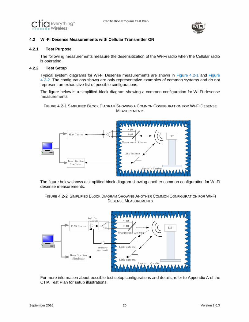
4.2.2 Test Setup Typical system diagrams for Wi-Fi Desense measurements are shown in Figure 4.2-1 and Figure 4.2-2. The configurations shown are only representative examples of common systems and do not represent an exhaustive list of possible configurations.
The figure below is a simplified block diagram showing a common configuration for Wi-Fi desense measurements.
FIGURE 4.2-1 SIMPLIFIED BLOCK DIAGRAM SHOWING A COMMON CONFIGURATION FOR WI-FI DESENSE MEASUREMENTS
EUT
Anechoic Chamber
Measurement Antenna
Base Station Simulator
Link antenna
θ-pol
φ-polWLAN Tester
The figure below shows a simplified block diagram showing another common configuration for Wi-Fi desense measurements.
FIGURE 4.2-2 SIMPLIFIED BLOCK DIAGRAM SHOWING ANOTHER COMMON CONFIGURATION FOR WI-FI DESENSE MEASUREMENTS
EUT
Anechoic Chamber
Measurement Antenna
Link antenna
Base Station Simulator
Link antennaAmplifier(optional)
Amplifier(optional) θ-pol
φ-polWLAN Tester
For more information about possible test setup configurations and details, refer to Appendix A of the CTIA Test Plan for setup illustrations.
Certification Program Test Plan
September 2016 21 Version 2.0.3
4.2.3 Test Procedures for Wi-Fi Radio Desensitization The Wi-Fi Desensitization tests consist of two groups of test scenarios related to the desensitization by closest cellular uplink frequency and desensitization by cellular uplink harmonics. Section 4.2.4 covers the test scenario and details for the closest cellular uplink frequency case while Section 4.2.5 covers the details related to the cellular uplink harmonics.
All cellular Tx parameter settings shall be set according to Section 5 of the CTIA Test Plan [1] or Appendix C.
For the Wi-Fi desensitization tests, configure the test as specified in Section 4.1.5 for the TIS (both cellular downlink and EUT cellular are disabled) testing with the exception of the setup corresponding to the desensitizing cellular signal that is specified here. Desense measurements shall be made at the same data rates used for the TIS measurements of Section 4.1.5.
The Wi-Fi Desensitization test consists of four basic steps as follows:
1. The EUT and chamber positioner(s) are moved to the location & polarization resulting in the best-radiated free-space sensitivity (EIS) measured for the closest, in frequency, channel for which the TIS has been determined, as covered in Section 4.1.5.
2. For the Wi-Fi channels specified in Sections 4.2.4 or 4.2.5, perform a single EIS measurement using the number of packets specified in Table 4.2-1.
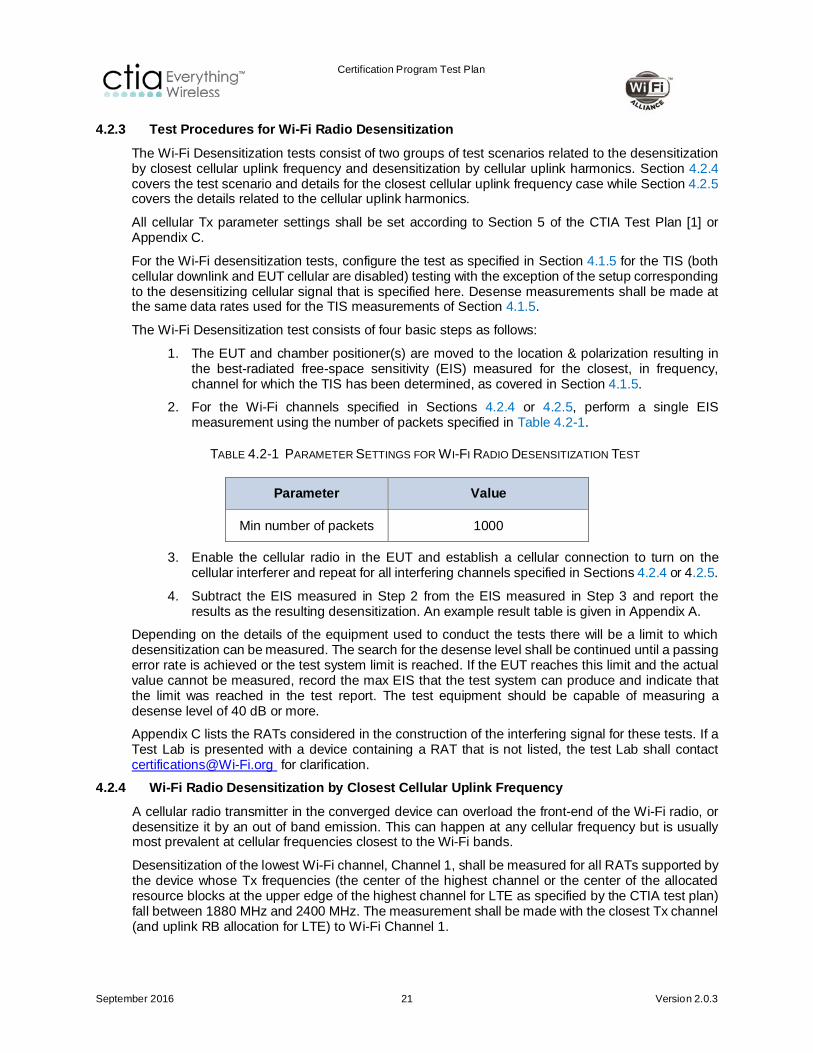
TABLE 4.2-1 PARAMETER SETTINGS FOR WI-FI RADIO DESENSITIZATION TEST
Parameter Value
Min number of packets 1000
3. Enable the cellular radio in the EUT and establish a cellular connection to turn on the cellular interferer and repeat for all interfering channels specified in Sections 4.2.4 or 4.2.5.
4. Subtract the EIS measured in Step 2 from the EIS measured in Step 3 and report the results as the resulting desensitization. An example result table is given in Appendix A.
Depending on the details of the equipment used to conduct the tests there will be a limit to which desensitization can be measured. The search for the desense level shall be continued until a passing error rate is achieved or the test system limit is reached. If the EUT reaches this limit and the actual value cannot be measured, record the max EIS that the test system can produce and indicate that the limit was reached in the test report. The test equipment should be capable of measuring a desense level of 40 dB or more.
Appendix C lists the RATs considered in the construction of the interfering signal for these tests. If a Test Lab is presented with a device containing a RAT that is not listed, the test Lab shall contact [email protected] for clarification.
4.2.4 Wi-Fi Radio Desensitization by Closest Cellular Uplink Frequency A cellular radio transmitter in the converged device can overload the front-end of the Wi-Fi radio, or desensitize it by an out of band emission. This can happen at any cellular frequency but is usually most prevalent at cellular frequencies closest to the Wi-Fi bands.
Desensitization of the lowest Wi-Fi channel, Channel 1, shall be measured for all RATs supported by the device whose Tx frequencies (the center of the highest channel or the center of the allocated resource blocks at the upper edge of the highest channel for LTE as specified by the CTIA test plan) fall between 1880 MHz and 2400 MHz. The measurement shall be made with the closest Tx channel (and uplink RB allocation for LTE) to Wi-Fi Channel 1.

Certification Program Test Plan
September 2016 22 Version 2.0.3
Desensitization of the highest supported Wi-Fi channel, (for example, Channel 11 or Channel 13) shall be measured for all RATs supported by the device whose Tx frequencies (the center of the lowest channel or the center of the allocated resource blocks at the lower edge of the lowest channel for LTE as specified by the CTIA test plan) fall between 2483.5 MHz and 3003.5 MHz. The measurement shall be made with the closest Tx channel (and uplink RB allocation for LTE) to highest supported Wi-Fi channel.
Choose the combinations with minimum frequency offset in Table 4.2-2 depending on what Wi-Fi channels and Cellular RATs the DUT supports.
If the device supports more than one band with the same RAT, then only the closest frequency (which is either the center of the channel or center of the resource blocks for LTE as specified by the CTIA test plan) to the 2400 MHz Wi-Fi band shall be tested.
All modes b, g and n (if supported by the Wi-Fi radio) shall be tested.
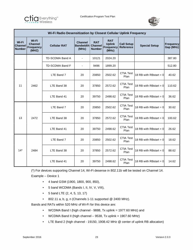
TABLE 4.2-2 CLOSEST CHANNEL COMBINATIONS
Wi-Fi Radio Desensitization by Closest Cellular Uplink Frequency
Wi-Fi Channel Number
Wi-Fi Channel
Frequency (MHZ)
Cellular RAT Channel
Bandwidth (MHz)
RAT Channel Number
RAT Uplink
Frequency (MHz)
Call Setup Reference Special Setup Frequency
Gap (MHz)
1 2412
CDMA PCS 1900 BC1 - 1175 1908.75 CTIA Test Plan 503.25
GSM1900 - 810 1909.80 CTIA Test Plan 502.20
WCDMA Band I - 9888 1977.60 CTIA Test Plan 434.40
WCDMA Band II - 9538 1907.60 CTIA Test Plan 504.40
LTE Band 1 10 18550 1983.42 CTIA Test Plan
12 RB with RBstart = 38 428.58
LTE Band 2 10 19150 1908.42 CTIA Test Plan
12 RB with RBstart = 38 503.58
LTE Band 25 5 26665 1914.03 CTIA Test Plan 8 RB with RBstart = 17 497.97
LTE Band 30 10 27710 2313.42 CTIA Test Plan
12 RB with RBstart = 38 98.58
LTE Band 39 20 38550 1917.38 CTIA Test Plan
18 RB with RBstart = 82 494.62
LTE Band 40 20 39550 2397.38 CTIA Test Plan
18 RB with RBstart = 82 14.62
Certification Program Test Plan
September 2016 23 Version 2.0.3
Wi-Fi Radio Desensitization by Closest Cellular Uplink Frequency
Wi-Fi Channel Number
Wi-Fi Channel
Frequency (MHZ)
Cellular RAT Channel
Bandwidth (MHz)
RAT Channel Number
RAT Uplink
Frequency (MHz)
Call Setup Reference Special Setup Frequency
Gap (MHz)
TD-SCDMA Band A - 10121 2024.20 387.80
TD-SCDMA Band F - 9496 1899.20 512.80
11 2462
LTE Band 7 20 20850 2502.62 CTIA Test Plan 18 RB with RBstart = 0 40.62
LTE Band 38 20 37850 2572.62 CTIA Test Plan 18 RB with RBstart = 0 110.62
LTE Band 41 20 39750 2498.62 CTIA Test Plan 18 RB with RBstart = 0 36.62
13 2472
LTE Band 7 20 20850 2502.62 CTIA Test Plan 18 RB with RBstart = 0 30.62
LTE Band 38 20 37850 2572.62 CTIA Test Plan 18 RB with RBstart = 0 100.62
LTE Band 41 20 39750 2498.62 CTIA Test Plan 18 RB with RBstart = 0 26.62
14* 2484
LTE Band 7 20 20850 2502.62 CTIA Test Plan 18 RB with RBstart = 0 18.62
LTE Band 38 20 37850 2572.62 CTIA Test Plan 18 RB with RBstart = 0 88.62
LTE Band 41 20 39750 2498.62 CTIA Test Plan 18 RB with RBstart = 0 14.62
(*) For devices supporting Channel 14, Wi-Fi desense in 802.11b will be tested on Channel 14.
Example – Device 1
• 4 band GSM (1900, 1800, 900, 850),
• 5 band WCDMA (Bands I, II, IV, V, VIII),
• 5 band LTE (2, 4, 5, 13, 17)
• 802.11 a, b, g, n (Channels 1-11 supported @ 2400 MHz).
Bands and RATs within 520 MHz of Wi-Fi for this device are:
• WCDMA Band I (high channel - 9888, Tx uplink = 1977.60 MHz) and
• WCDMA Band II (high channel – 9538, Tx uplink = 1907.60 MHz)
• LTE Band 2 (high channel - 19150, 1908.42 MHz @ center of uplink RB allocation)

Certification Program Test Plan
September 2016 24 Version 2.0.3
• GSM 1900 (high channel – 810, 1909.80 MHz)
Set Wi-Fi to lowest supported channel, Channel 1, 2412 MHz, for b/g/n modes.
Test the following
• Wi-Fi Channel 1 against GSM 1900 Channel 810, 1909.80 MHz
• Wi-Fi Channel 1 against WCDMA Band I Channel 9888, 1977.60 MHz
• Wi-Fi Channel 1 against LTE Band 2 Channel 19150, 1908.42 MHz, center of uplink RB allocation
WCDMA Band II is also within the range, but its uplink frequency (1907.6 MHz, Channel 9538) is lower in frequency than WCDMA Band I and the same RAT does not need to be tested again.
Example – Device 2
• Single band LTE TDD Band 41 device and 802.11 b, g, n (Channels 1-11).
Bands and RATs within 520 MHz of Wi-Fi for this device are:
• LTE TDD Band 41 (low channel, 39750, 2498.62 MHz @ center of uplink RB allocation).
Set Wi-Fi to highest supported channel, Channel 11, 2462 MHz, for b/g/n modes.
Test the following
• Wi-Fi Channel 11 against LTE TDD Band 41 Channel 39750, 2498.62 MHz @ center of uplink RB allocation
4.2.5 Wi-Fi Radio Desensitization by Cellular Radio Uplink Harmonics The cellular transmitter can produce unwanted harmonics that may interfere with certain Wi-Fi channels depending upon the combination of cellular technologies and Wi-Fi channels implemented in a converged device. Appendix F shows all known RATs and their interaction with Wi-Fi channels and many other details in a large spreadsheet. A subset of Wi-Fi channels has been selected that cover the interaction with as many RATs as possible to simplify the test selection and these are compiled into Table 4.2-3.
The EUT desensitization shall be tested for all relevant interactions in Table 4.2-3. The cellular radio configuration will be set according to the Call Setup Reference, in Table 4.2-3, except for those parameters specifically defined within the table. Relevant interaction is defined by supported RAT implementation or as specified by the manufacturer.

Certification Program Test Plan
September 2016 25 Version 2.0.3
TABLE 4.2-3 DESENSITIZATION CASES
Cellular RAT & Wi-Fi channel pairs for Testing Harmonic Desensitization of Wi-Fi by Cellular Uplink Tx
Wi-Fi Channel Test Case Cellular RAT
RAT Channel Number
RAT Uplink Frequency
(MHz) Call Setup Reference Special
Setup
11
11.1 GSM 850 128 824.2 CTIA Test Plan
11.2 CDMA 800 Cellular BC0 1013 824.7 CTIA Test Plan
11.3 WCDMA 850 3GPP Band V 4132 826.4 CTIA Test Plan
11.4 LTE Band 5 (not needed if LTE Band 26 is tested) 20450 825.58 CTIA Test Plan
10.0 MHz BW, UL: 12
RB, RBstart = 0
11.5 LTE Band 26 26815 824.97 CTIA Test Plan
5.0 MHz BW, UL: 8
RB, RBstart=0
13
13.1 GSM 850 128 824.2 CTIA Test Plan
13.2 CDMA 800 Cellular BC0 1013 824.7 CTIA Test Plan
13.3 WCDMA 850 3GPP Band V 4132 826.4 CTIA Test Plan
13.4 LTE Band 5(not needed if LTE Band 26 is tested) 20450 825.58 CTIA Test Plan
10.0 MHz BW, UL: 12
RB, RBstart = 0
13.5 LTE Band 26 26815 824.97 CTIA Test Plan
5.0 MHz BW, UL: 8
RB, RBstart=0
`
Certification Program Test Plan
September 2016 26 Version 2.0.3
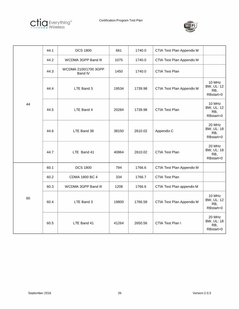
44
44.1 DCS 1800 661 1740.0 CTIA Test Plan Appendix M
44.2 WCDMA 3GPP Band III 1075 1740.0 CTIA Test Plan Appendix M
44.3 WCDMA 2100/1700 3GPP Band IV 1450 1740.0 CTIA Test Plan
44.4 LTE Band 3 19534 1739.98 CTIA Test Plan Appendix M
10 MHz BW, UL: 12
RB, RBstart=0
44.5 LTE Band 4 20284 1739.98 CTIA Test Plan
10 MHz BW, UL: 12
RB, RBstart=0
44.6 LTE Band 38 38150 2610.02 Appendix C
20 MHz BW, UL: 18
RB, RBstart=0
44.7 LTE Band 41 40864 2610.02 CTIA Test Plan
20 MHz BW, UL: 18
RB, RBstart=0
60
60.1 DCS 1800 794 1766.6 CTIA Test Plan Appendix M
60.2 CDMA 1800 BC 4 334 1766.7 CTIA Test Plan
60.3 WCDMA 3GPP Band III 1208 1766.6 CTIA Test Plan appendix M
60.4 LTE Band 3 19800 1766.58 CTIA Test Plan Appendix M
10 MHz BW, UL: 12
RB, RBstart=0
60.5 LTE Band 41 41264 2650.56 CTIA Test Plan \
20 MHz BW, UL: 18
RB, RBstart=0

Certification Program Test Plan
September 2016 27 Version 2.0.3
Example – Device 1
• 4 band GSM (1900, 1800, 900, 850),
• 5 band WCDMA (Bands I, II, IV, V, VIII),
• 5 band LTE (2, 4, 5, 13, 17)
• 802.11 b, g, n (Channels 1-11 supported @ 2400 MHz).
• 802.11 a Channels 36 – 64
Test the following
• Wi-Fi Channel 11 against GSM 850 Channel 128, 824.2 MHz
• Wi-Fi Channel 11 against WCDMA 850 3GPP Band V Channel 4357, 826.4 MHz
• Wi-Fi Channel 11 against LTE Band 5 Channel 20450, 825.6 MHz
• Wi-Fi Channel 44 against DCS 1800 GSM 1800 Channel 661, 1740.0 MHz
• Wi-Fi Channel 44 against WCDMA 3GPP Band III Channel 1300, 1740.0 MHz
124
124.1 GSM 1900 628 1873.4 CTIA Test Plan
124.2 CDMA 1900 PCS BC1 468 1873.4 CTIA Test Plan
124.3 WCDMA 1900 3GPP Band II 9367 1873.4 CTIA Test Plan
124.4 LTE Band 2 (not needed if LTE Band 25 is tested) 18866 1873.18 CTIA Test Plan
10 MHz BW, UL: 12
RB, RBstart=0
124.5 LTE Band 25 26287 1873.17 CTIA Test Plan 5 MHz BW, UL: 8 RB, RBstart=0
132 132.1 TD-SCDMA Band F1 9436 1887.2 Appendix C
140 140.1 LTE Band 39 38524 1900.0 Appendix C
20 MHz BW, UL: 18
RB, RBstart=0
140.2 TD-SCDMA Band F2 9492 1898.4 Appendix C
157
157.1 CDMA 2000 BC 6 167 1928.4 CTIA Test Plan
157.2 WCDMA 3GPP Band I 9642 1928.4 CTIA Test Plan Appendix M
157.3 LTE Band 1 18118 1928.38 CTIA Test Plan Appendix M
10 MHz BW, UL: 12
RB, RBstart=0
Certification Program Test Plan
September 2016 28 Version 2.0.3
• Wi-Fi Channel 44 against LTE Band 4 Channel 20250, 1740.0 MHz
• Wi-Fi Channel 60 against DCS 1800 GSM 1800 Channel 794, 1766.6 MHz
Example – Device 2
• Single band LTE TDD Band 41 device and 802.11 b, g, n (Channels 1-11).
No test is required.
4.2.6 Results Results shall be reported in dB.
There are no Pass/Fail criteria. Refer to Appendix A for sample report templates.
4.3 Cellular Desense Measurements with Wi-Fi transmitter ON
4.3.1 Test Purpose The purpose of this test is to conduct cellular desensitization test when the EUT’s Wi-Fi transmitter is ON.
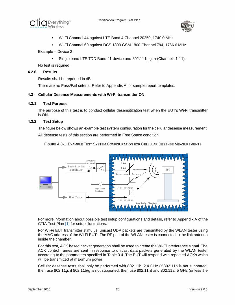
4.3.2 Test Setup The figure below shows an example test system configuration for the cellular desense measurement.
All desense tests of this section are performed in Free Space condition.
FIGURE 4.3-1 EXAMPLE TEST SYSTEM CONFIGURATION FOR CELLULAR DESENSE MEASUREMENTS
EUT
Anechoic Chamber
Measurement Antenna
Link antennaWLAN Tester
Link antennaAmplifier(optional)
Amplifier(optional) θ-pol
φ-polBase Station Simulator
For more information about possible test setup configurations and details, refer to Appendix A of the CTIA Test Plan [1] for setup illustrations.
For Wi-Fi EUT transmitter stimulus, unicast UDP packets are transmitted by the WLAN tester using the MAC address of the Wi-Fi EUT. The RF port of the WLAN tester is connected to the link antenna inside the chamber.
For this test, ACK based packet generation shall be used to create the Wi-Fi interference signal. The ACK control frames are sent in response to unicast data packets generated by the WLAN tester according to the parameters specified in Table 3 4. The EUT will respond with repeated ACKs which will be transmitted at maximum power.
Cellular desense tests shall only be performed with 802.11b, 2.4 GHz (if 802.11b is not supported, then use 802.11g, if 802.11b/g is not supported, then use 802.11n) and 802.11a, 5 GHz (unless the

Certification Program Test Plan
September 2016 29 Version 2.0.3
device only supports 802.11n, then use 802.11n). Data rates of Table 3 1 shall be used for the Wi-Fi interference signal.
All desense tests of this section are performed according to the configurations specified in Appendix B.
Cellular antenna selection for devices that support receive diversity is according to the following:
1. For all RATs listed in the CTIA Test Plan [1] that support diversity, the device shall be tested using only the primary antenna (as defined by the CTIA Test Plan [1]).
2. For all RATs listed in CTIA Test Plan [1] Appendix M “Optional GSM, UMTS and LTE Bands (Informative)” and for RATs listed in Appendix C of this test plan that support receive diversity, the device shall be tested per the 3GPP OTA test plan diversity requirements using only the primary antenna.
4.3.3 Test Procedure for GSM, CDMA and UMTS RATs listed in the CTIA Test Plan For GSM, CDMA and UMTS RATs listed in CTIA Test Plan [1] Section 6, perform the following steps.
Initial Conditions
1. Turn on the Wi-Fi radio and let the Wi-Fi EUT associate with the WLAN tester using appropriate settings of the EUT and WLAN tester.
2. Start Wi-Fi EUT Transmitter Stimulus as specified in Section 4.3.2.
Test Procedures
3. With Wi-Fi Radio on, perform the Relative Sensitivity on Intermediate Channels test at all intermediate channels according to the appropriate Receive Performance Test Procedure section of the CTIA Test Plan [1].
4. Compare the resulting digital error rate or throughput rate as specified in the CTIA Test Plan [1] and determine which channels are desensitized beyond requirements specified in the CTIA Test Plan [1].
5. Repeat Step 3 and Step 4 for all RATS and corresponding supporting bands.
6. Report only the intermediate channels that exceed the limit as specified in the CTIA Test Plan [1].
4.3.4 Test Procedure for RATs Listed in Appendix C here and non-LTE RATs listed in the CTIA Test Plan Appendix M.
In this case, the Intermediate Channels are not defined and M1 margin values (as described in the CTIA Test Plan [1]) may not be available as TIS limits are not available.
For all non LTE RATs listed in the CTIA Test Plan [1] Appendix M “Optional GSM, UMTS and LTE Bands (Informative)” and RATs listed in Appendix C of this test plan, perform the following steps.
Test Procedures
1. Determine the TIS of the EUT at the low channel with the Wi-Fi radio transmitter switched OFF, using the data captured previously per the procedures in the CTIA Test Plan [1].
2. Use the CTIA Test Plan [1] procedures to determine the position and polarization that results in the maximum EIS value associated to Step 1.
3. Use the corresponding position and polarization of Step 2 and measure the EIS(peak) of the EUT at the low channel with the Wi-Fi radio transmitter switched OFF.
4. Capture the measured EIS result as Value A Low.
Certification Program Test Plan
September 2016 30 Version 2.0.3
5. Turn on the Wi-Fi radio and let the Wi-Fi EUT associate with the WLAN tester using appropriate settings of the EUT and WLAN tester.
6. Start Wi-Fi EUT Transmitter Stimulus as specified in Section 4.3.2.
7. Without re-positioning and keeping the same corresponding position and polarization of Step 2, measure the EIS(peak) of the EUT at the low channel with the Wi-Fi radio transmitter switched ON. Capture the result as Value B Low.
8. Repeat Step 1 to Step 7 for the mid and high channels.
9. Repeat Step 1 to Step 8 for all RATs and corresponding supporting bands.
4.3.5 Test Procedure for all LTE cases Note: The CTIA Test Plan [1] includes a list of LTE intermediate channels for Northern American bands in Section O.8.1, however, no M1 margin values are available as the test plan does not currently specify minimum TIS requirements for LTE devices.
For all LTE RATs perform the following steps.
Test Procedures Follow the procedure of Section 4.3.4.
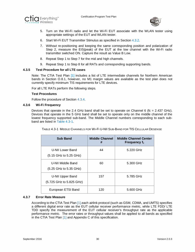
4.3.6 Wi-Fi Frequency Devices that operate in the 2.4 GHz band shall be set to operate on Channel 6 (fc = 2.437 GHz). Devices that operate in the 5 GHz band shall be set to operate only on the middle channel of the lowest frequency supported sub-band. The Middle Channel numbers corresponding to each sub-band are listed in Table 4.3-1.
TABLE 4.3-1 MIDDLE CHANNELS FOR WI-FI U-NII SUB-BAND FOR TIS CELLULAR DESENSE
Sub Band Middle Channel #
Middle Channel Center Frequency fc
U-NII Lower Band
(5.15 GHz to 5.25 GHz)
44 5.220 GHz
U-NII Middle Band
(5.25 GHz to 5.35 GHz)
60 5.300 GHz
U-NII Upper Band
(5.725 GHz to 5.825 GHz)
157 5.785 GHz
European ETSI Band 120 5.600 GHz
4.3.7 Error Rate Measure According to the CTIA Test Plan [1],each airlink protocol (such as GSM, CDMA, and UMTS) specifies a different digital error rate as the EUT cellular receiver performance metric, while LTE FDD/ LTE TDD specify the measurement of the EUT cellular receiver’s throughput rate as the applicable performance metric. The error rates or throughput values shall be applied to all bands as specified in the CTIA Test Plan [1] and Appendix C of this specification.
Certification Program Test Plan
September 2016 31 Version 2.0.3
4.3.8 Results There are no Pass/Fail criteria.
When performing the test according to Section 4.3.3, results shall be reported by giving the channel(s) exceeding the limit. When performing the test according to Section 4.3.4, results shall be reported in dBm for the EIS values.
Refer to Appendix A for sample report templates.

Certification Program Test Plan
September 2016 32 Version 2.0.3
Appendix A Summary Test Report
The following content shall be included in the test report. The tables are provided as examples for information.
TABLE A-1 SAMPLE SUMMATION
Manufacturer
Model
Wi-Fi Alliance CID2
CTIA Request #
Serial Number (e.g., MEID, IMEI).
Regulatory Approval ID (e.g., FCCID)
Hardware Version
Software Version
2 Vendor supplies the Wi-Fi Alliance CID (Certification Identifier) during the CWG application process.
Certification Program Test Plan
September 2016 33 Version 2.0.3
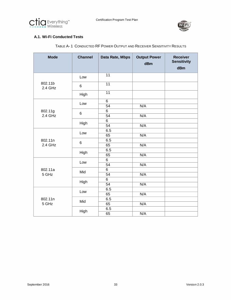
A.1. Wi-Fi Conducted Tests
TABLE A- 1 CONDUCTED RF POWER OUTPUT AND RECEIVER SENSITIVITY RESULTS
Mode Channel Data Rate, Mbps Output Power dBm
Receiver Sensitivity
dBm
802.11b 2.4 GHz
Low 11
6 11
High 11
802.11g 2.4 GHz
Low 6 54 N/A
6 6 54 N/A
High 6 54 N/A
802.11n 2.4 GHz
Low 6.5 65 N/A
6 6.5 65 N/A
High 6.5 65 N/A
802.11a 5 GHz
Low 6 54 N/A
Mid 6 54 N/A
High 6 54 N/A
802.11n 5 GHz
Low 6.5 65 N/A
Mid 6.5 65 N/A
High 6.5 65 N/A

Certification Program Test Plan
September 2016 34 Version 2.0.3
A.2. Total Radiated Power (TRP)and Total Isotropic Sensitivity (TIS) for 2.4 GHz 802.11b, 802.11g and 802.11n
TABLE A- 2 TRP FOR 2.4 GHZ 802.11B/G/N
Mode Channel Data Rate, Mbps Result, dBm
TRP
IEEE 802.11b 6 11
IEEE 802.11g 6 6
IEEE 802.11n 6 6.5
TABLE A- 3 TIS FOR 2.4 GHZ 802.11B/G/N
Mode Channel Data Rate, Mbps
Result, dBm TIS
IEEE 802.11b 6 11
IEEE 802.11g 6 54
IEEE 802.11n 6 65
Certification Program Test Plan
September 2016 35 Version 2.0.3
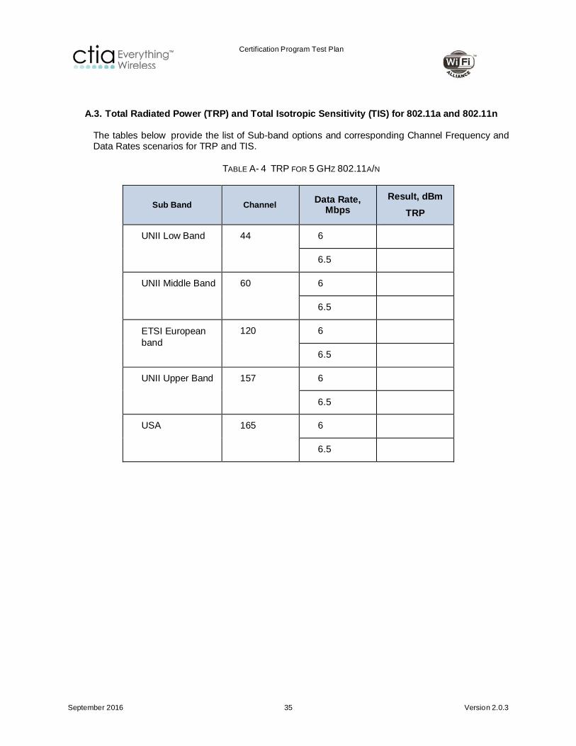
A.3. Total Radiated Power (TRP) and Total Isotropic Sensitivity (TIS) for 802.11a and 802.11n
The tables below provide the list of Sub-band options and corresponding Channel Frequency and Data Rates scenarios for TRP and TIS.
TABLE A- 4 TRP FOR 5 GHZ 802.11A/N
Sub Band Channel Data Rate, Mbps
Result, dBm TRP
UNII Low Band 44 6
6.5
UNII Middle Band 60 6
6.5
ETSI European band
120 6
6.5
UNII Upper Band 157 6
6.5
USA 165 6
6.5
Certification Program Test Plan
September 2016 36 Version 2.0.3
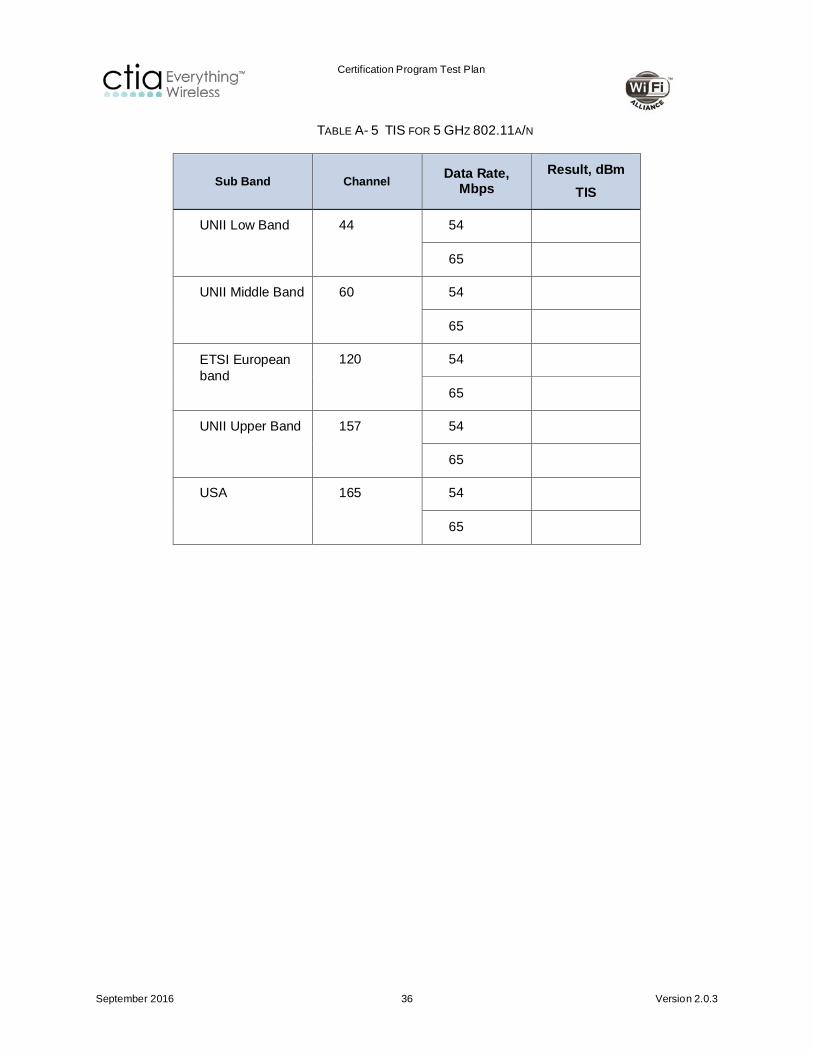
TABLE A- 5 TIS FOR 5 GHZ 802.11A/N
Sub Band Channel Data Rate, Mbps
Result, dBm TIS
UNII Low Band 44 54
65
UNII Middle Band 60 54
65
ETSI European band
120 54
65
UNII Upper Band 157 54
65
USA 165 54
65

Certification Program Test Plan
September 2016 37 Version 2.0.3
A.4. Wi-Fi Desense Measurements (with cellular transmitter on)
TABLE A- 6 WI-FI RADIO DESENSITIZATION BY CLOSEST CELLULAR UPLINK FREQUENCY
802.11 Closest Cellular Uplink Frequency
802.11 Reference Polarization
Reference Position
Desense dB
Max provided EIS in case of
Complete Failure dBm Mode Channel Mode Channel Data
Rate, Mbps
Theta Phi
802.11b
802.11g
802.11n 2.4 GHz
Note: In case of complete failure, include the maximum EIS that the test system can provide in the last column; leave unused otherwise.
TABLE A- 7 WI-FI RADIO DESENSITIZATION BY CELLULAR RADIO UPLINK HARMONICS 802.11B/G/N/A
802.11 Cellular Uplink Frequency
802.11 Reference Polarization
Reference
Position
Desense dB
Max provided EIS in case of
Complete Failure dBm
Mode Channel Mode Channel Data Rate, Mbps
Theta Phi
802.11b
802.11g
802.11n 2.4 GHz
802.11a 5 GHz
802.11n 5 GHz
Note: In case of complete failure, include the maximum EIS that the test system can provide in the last column; leave blank otherwise.
A.5. Cellular Desense Measurements (with Wi-Fi transmitter on)
Reporting Format for Intermediate Channel Sensitivity Tests according to Section 4.3.3.

Certification Program Test Plan
September 2016 38 Version 2.0.3
TABLE A- 8 CELLULAR DESENSE TEST RESULTS FOR 802.11B OPERATION (WI-FI 2.4 GHZ BAND)
Cellular Technology/
Band
Wi-Fi Channel Reference Polarization
Reference Position Thetao
Reference Position Phio
Intermediate Channels Exceeding
Limit
802.11b Ch. 6 (2.437GHz)
TABLE A- 9 CELLULAR DESENSE TEST RESULTS FOR 802.11A OPERATION
Cellular Technology/
Band
Wi-Fi Channel Reference Polarization
Reference Position Thetao
Reference Position
Phio
Intermediate Channels
Exceeding Limit
802.11a middle channel of the lowest supported sub-band
Reporting Format for EIS Tests according to Section 4.3.4.
TABLE A- 10 CELLULAR DESENSE TEST RESULTS FOR 802.11B OPERATION (WI-FI 2.4 GHZ BAND)
Cellular Technology
Channel
Wi-Fi Channel Reference Polarization
Reference Position Thetao
Reference Position
Phio
EIS Value A
dBm
EIS Value B
dBm
Low Mid High Low Mid High
802.11b Ch. 6 (2.437GHz)

Certification Program Test Plan
September 2016 39 Version 2.0.3
TABLE A- 11 CELLULAR DESENSE TEST RESULTS FOR 802.11A OPERATION
Cellular Technology
Channel
Wi-Fi Channel Reference Polarization
Reference Position Thetao
Reference Position
Phio
EIS Value A dBm
EIS Value B dBm
Low Mid High Low Mid High 802.11a
middle channel of the lowest supported sub-band
Certification Program Test Plan
September 2016 40 Version 2.0.3
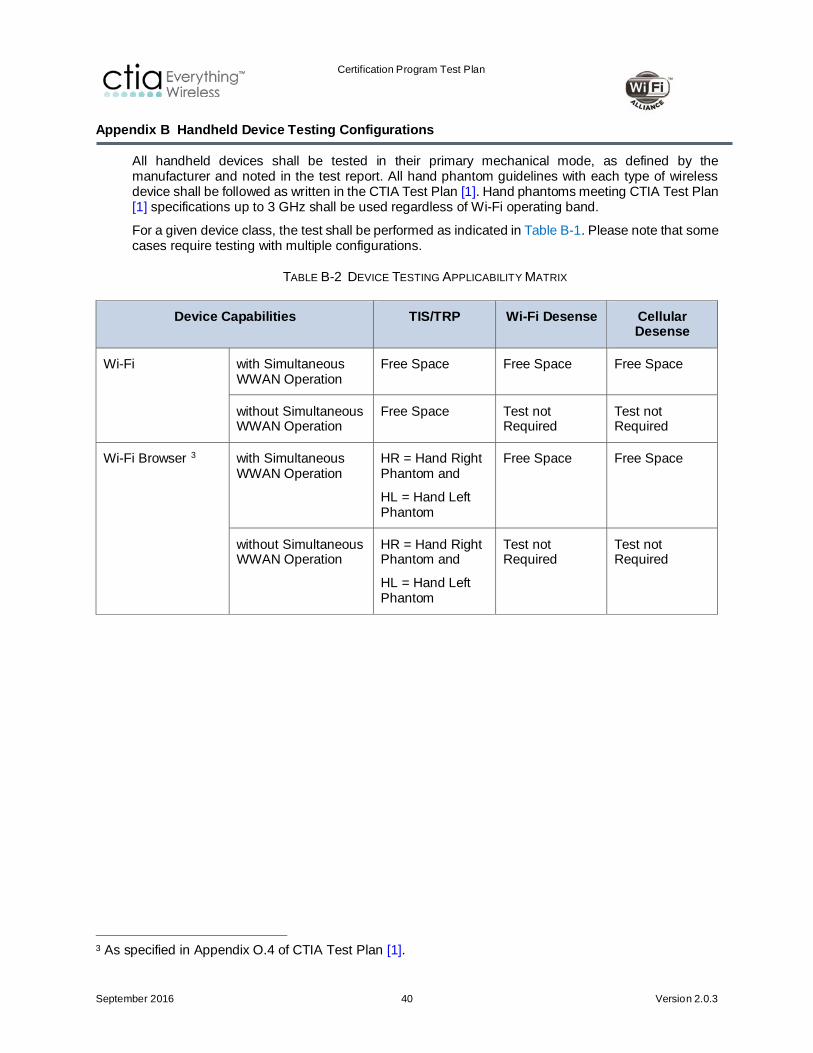
Appendix B Handheld Device Testing Configurations
All handheld devices shall be tested in their primary mechanical mode, as defined by the manufacturer and noted in the test report. All hand phantom guidelines with each type of wireless device shall be followed as written in the CTIA Test Plan [1]. Hand phantoms meeting CTIA Test Plan [1] specifications up to 3 GHz shall be used regardless of Wi-Fi operating band.
For a given device class, the test shall be performed as indicated in Table B-1. Please note that some cases require testing with multiple configurations.
TABLE B-2 DEVICE TESTING APPLICABILITY MATRIX
Device Capabilities TIS/TRP Wi-Fi Desense Cellular Desense
Wi-Fi with Simultaneous WWAN Operation
Free Space Free Space Free Space
without Simultaneous WWAN Operation
Free Space Test not Required
Test not Required
Wi-Fi Browser 3
with Simultaneous WWAN Operation
HR = Hand Right Phantom and
HL = Hand Left Phantom
Free Space Free Space
without Simultaneous WWAN Operation
HR = Hand Right Phantom and
HL = Hand Left Phantom
Test not Required
Test not Required
3 As specified in Appendix O.4 of CTIA Test Plan [1].
Certification Program Test Plan
September 2016 41 Version 2.0.3
Appendix C Radio Access Technologies that Require Testing, but are not Normative in the CTIA Test Plan
C.1 TD-SCDMA
The TIS measurements of TD-SCDMA shall be the same as described in the latest approved version of the CTIA Test Plan [1] unless otherwise defined in this section. This section only defines differences compared to CTIA Test Plan [1] and those parts shall be performed referring to 3GPP 34.114, Section 6.4. Using the Generic Call Setup procedures described in 3GPP TS 34.108 Section 7, page the EUT and place it into the loopback mode as described in 3GPP TS 34.109 Section 5.3; set the UL and DL reference measurement channel as described in 3GPP 34.122, C.2.1.2 and C.3.1.2.
Tests shall be performed for low, mid and high channels across the TD-SCDMA bands supported by the EUT, as defined in 3GPP 34.114, Section 4.1.3, Table 4.2-2 and Table 4.2-3.
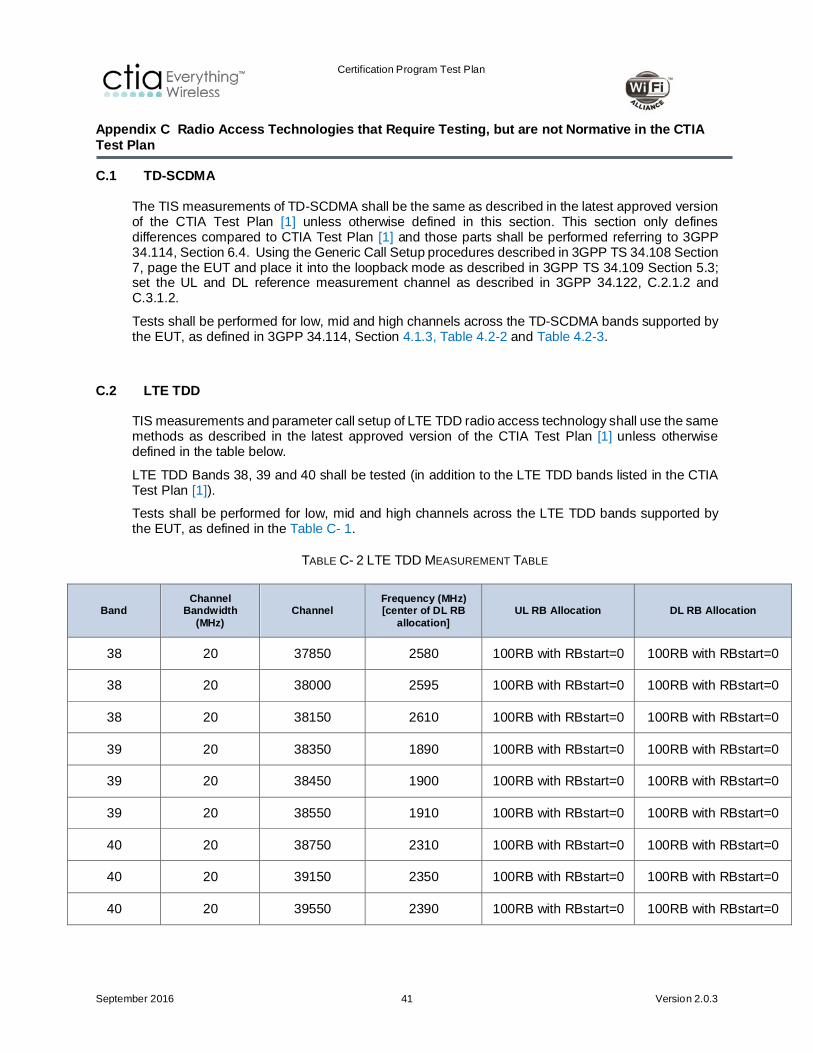
C.2 LTE TDD
TIS measurements and parameter call setup of LTE TDD radio access technology shall use the same methods as described in the latest approved version of the CTIA Test Plan [1] unless otherwise defined in the table below.
LTE TDD Bands 38, 39 and 40 shall be tested (in addition to the LTE TDD bands listed in the CTIA Test Plan [1]).
Tests shall be performed for low, mid and high channels across the LTE TDD bands supported by the EUT, as defined in the Table C- 1.
TABLE C- 2 LTE TDD MEASUREMENT TABLE
Band Channel
Bandwidth (MHz)
Channel Frequency (MHz) [center of DL RB
allocation] UL RB Allocation DL RB Allocation
38 20 37850 2580 100RB with RBstart=0 100RB with RBstart=0
38 20 38000 2595 100RB with RBstart=0 100RB with RBstart=0
38 20 38150 2610 100RB with RBstart=0 100RB with RBstart=0
39 20 38350 1890 100RB with RBstart=0 100RB with RBstart=0
39 20 38450 1900 100RB with RBstart=0 100RB with RBstart=0
39 20 38550 1910 100RB with RBstart=0 100RB with RBstart=0
40 20 38750 2310 100RB with RBstart=0 100RB with RBstart=0
40 20 39150 2350 100RB with RBstart=0 100RB with RBstart=0
40 20 39550 2390 100RB with RBstart=0 100RB with RBstart=0
Certification Program Test Plan
September 2016 42 Version 2.0.3
Appendix D Notebook and Tablet Requirements
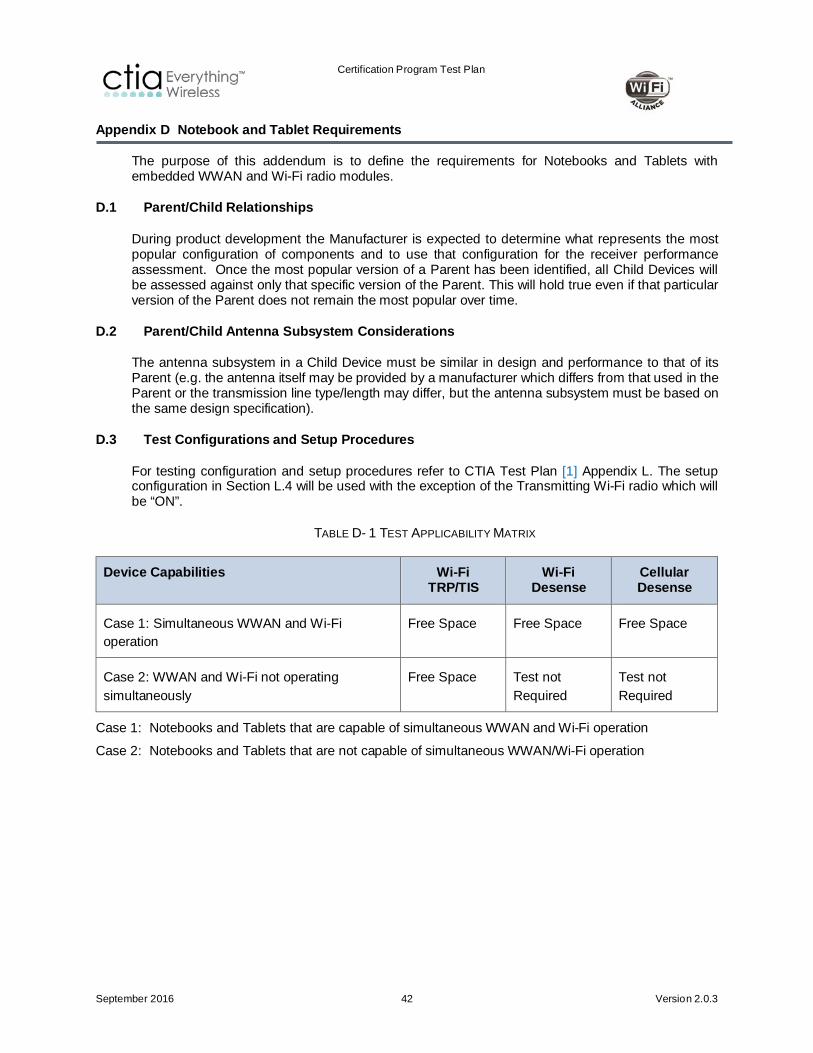
The purpose of this addendum is to define the requirements for Notebooks and Tablets with embedded WWAN and Wi-Fi radio modules.
D.1 Parent/Child Relationships
During product development the Manufacturer is expected to determine what represents the most popular configuration of components and to use that configuration for the receiver performance assessment. Once the most popular version of a Parent has been identified, all Child Devices will be assessed against only that specific version of the Parent. This will hold true even if that particular version of the Parent does not remain the most popular over time.
D.2 Parent/Child Antenna Subsystem Considerations
The antenna subsystem in a Child Device must be similar in design and performance to that of its Parent (e.g. the antenna itself may be provided by a manufacturer which differs from that used in the Parent or the transmission line type/length may differ, but the antenna subsystem must be based on the same design specification).
D.3 Test Configurations and Setup Procedures
For testing configuration and setup procedures refer to CTIA Test Plan [1] Appendix L. The setup configuration in Section L.4 will be used with the exception of the Transmitting Wi-Fi radio which will be “ON”.
TABLE D- 1 TEST APPLICABILITY MATRIX
Device Capabilities Wi-Fi TRP/TIS
Wi-Fi Desense
Cellular Desense
Case 1: Simultaneous WWAN and Wi-Fi operation
Free Space Free Space Free Space
Case 2: WWAN and Wi-Fi not operating simultaneously
Free Space Test not Required
Test not Required
Case 1: Notebooks and Tablets that are capable of simultaneous WWAN and Wi-Fi operation
Case 2: Notebooks and Tablets that are not capable of simultaneous WWAN/Wi-Fi operation

Certification Program Test Plan
September 2016 43 Version 2.0.3
TABLE D- 2 DEFINITIONS
Child Device A Notebook platform utilizing an embedded WWAN Module, which is derived from a Parent Notebook platform. A Child Device is unique in that the only allowable changes relative to its Parent product are those applicable to the Notebook platform itself.
Module Modules are finished WWAN radio devices that do not directly connect to a host via a standardized external interface such as PCMCIA, RS-232, USB, PCIExpress, etc. A module may or may not include an integral antenna system or SIM/USIM interface.
Notebook See definition in CTIA Test Plan [1] Appendix L.
Parent A device (of any type) from which a Child device can be derived.
Simultaneous operation
A Notebook/Tablet that is capable of simultaneous Wi-Fi/Cellular operation and the user experience is that both radios are on at the same time. An example would be Hot Spot operation.
Tablet See definition in CTIA Test Plan [1] Appendix L.
WLAN Wireless Local Area Network (WLAN) links two or more devices using some wireless distribution method and usually providing a connection through an access point to the wider internet. Most modern WLANs are based on IEEE 802.11 standards, marketed under the Wi-Fi brand name.
WWAN Wireless Wide Area Network refers to cellular airlink technologies as noted in Section 1.2.

Certification Program Test Plan
September 2016 44 Version 2.0.3
Appendix E Wi-Fi-LTE Emulator Test Equipment Notes when Testing EUTs that Support LTE Band 40 or 41 (Informative)
This is an informative appendix. The information in this appendix is to inform test labs that care must be used with test equipment when performing tests with EUTs that support LTE Band 40 or 41. With an incorrect test setup, results may be incorrect because of test equipment desense. Proper RF isolation is required between the cellular and Wi-Fi emulators. The test diagrams shown in this appendix are examples and variations of the test setup may differ or may not be required for each test lab.
Proper Wi-Fi and LTE emulator test equipment setup is required for Wi-Fi or cellular desense measurements for EUTs that support LTE Bands 40 or 41. LTE Bands 40 and 41 are next to the 2.4 GHz Wi-Fi band with little or no guard bands (see the figures that follow). There is the possibility that the Wi-Fi or LTE emulator would be unable to attach to the EUT when performing these measurements due to test equipment immunity issues. The test lab must insure they are measuring the over the air EUT Wi-Fi or cellular desense and not Wi-Fi or LTE emulator test equipment immunity.
FIGURE E- 1 LTE BAND 40 AND WI-FI 2.4 GHZ FREQUENCY DIAGRAM
FIGURE E- 2 LTE BAND 41 AND WI-FI 2.4 GHZ FREQUENCY DIAGRAM
The test lab can verify Wi-Fi emulator test equipment immunity with the example test equipment diagram in the figure below. RF cavity tuned notch and/or bandpass filters are used to ensure the EUT is not desensed by the LTE device and for the LTE device to stay attached to the LTE emulator due to interference from the Wi-Fi. Attenuators can be used to simulate expected RF levels present at the Wi-Fi emulator while performing Wi-Fi EUT over the air desense measurements. Perform sensitivity measurements with the EUT only (without LTE Band 40) and note results. Then attach LTE Band 40 EUT to the LTE emulator (at maximum output power). With the LTE Band 40 EUT

Certification Program Test Plan
September 2016 45 Version 2.0.3
attached, re-measure the Wi-Fi EUT. If the Wi-Fi sensitivity measurements are the same and Wi-Fi/LTE EUTs remain attached, the Wi-Fi emulator is immune to the adjacent channel interference. LTE base station emulator test equipment immunity can be verified by exchanging the positions of the emulators, RF filters and EUTs in the diagram.
FIGURE E- 3 WI-FI EMULATOR TEST EQUIPMENT VERIFICATION TEST SETUP (TO TEST THE LTE BASE STATION
If the Wi-Fi or LTE emulator does show immunity problems, Figure E- 4 diagram shows an example on how to eliminate these problems (use RF filters as needed). If the lab is using an RF compression amplifier for the LTE input emulator, the RF filter must be installed after the output of the amplifier. If the device can stay attached to the LTE emulator, no RF filter is required. If the lab is using an RF preamplifier for the Wi-Fi emulator input, the RF filter should be connected to the input of the preamplifier. Care must be used when tuning the RF filters. If a Wi-Fi bandpass RF filter is used, be sure to add its loss into the system path loss and remove the filters when performing Wi-Fi TRP or TIS measurements.
FIGURE E- 5 EXAMPLE TEST SYSTEM DIAGRAM (ONLY FOR WI-FI DESENSE OR LTE CELLULAR DESENSE TESTS, IF THE EUT SUPPORTS LTE BAND 40)

Certification Program Test Plan
September 2016 46 Version 2.0.3
Appendix F Table of Wi-Fi Radio channels interfered by Cellular Radio Harmonics
The cellular radio configuration will be set according to the Call Setup Reference, in the table below, except for those parameters specifically defined within the table.

Certification Program Test Plan
September 2016 47 Version 2.0.3
Band Edges
824.2 848.8 880.2 914.8 1710.2 1784.8 1850.2 1909.8 824.7 848.31 1711.25 1753.75 1751.25 1778.75 1851.25 1908.75 1920 1980
869.2 893.8 925.2 959.8 1805.2 1879.8 1930.2 1989.8 869.7 881.52 2111.25 2153.75 1841.25 1868.75 1931.25 1988.75 2110 2170
Chan Freq Chan Freq Chan Freq Chan Freq Chan Freq Chan Freq Chan Freq Chan Freq Chan Freq Chan Freq
1 2412
2 2417
3 2422
4 2427
5 2432
6 2437
7 2442
8 2447
9 2452
10 2457
11 2462 128 824.2 1013 824.7
12 2467
13 2472 128 824.2 1013 824.7
14 2484 147 828 77 827.3
802.
11b/
g/n
Desensitization of Wi-Fi Rx by Cellular Tx Uplink
Black boxes indicate Wi-Fi Rx vulnerability due to Cellular uplink Tx
CDMA 1800 BC 4
Asia
CTIA Test Plan [1] Section 5.2
Uplink Freq
Downlink Freq
Special setup
CTIA Test Plan [1] Section 5.2
CTIA Test Plan [1] Section 5.2
CTIA Test Plan [1] Section 5.2
CTIA Test Plan [1] Section 5.2
CTIA Test Plan [1] Section 5.4
Suggested alternate name
Call setup defined in reference document
CTIA Test Plan [1] Section 5.4
CTIA Test Plan [1] Appendix M
CTIA Test Plan [1] Appendix M
North America North America, Asia AsiaRegion North America, South America, Asia
South America, EU, Asia, Australia.
Africa
South America, EU, Asia, Australia.
Africa
North America, South America North America, Asia
CDMA 2100/1700 AWS-1 BC 15
CDMA 1900 PCS BC1 CDMA 2000 BC6RAT GSM 850 E-GSM 900 DCS 1800 GSM 1900 CDMA 800 Cellular
BC0
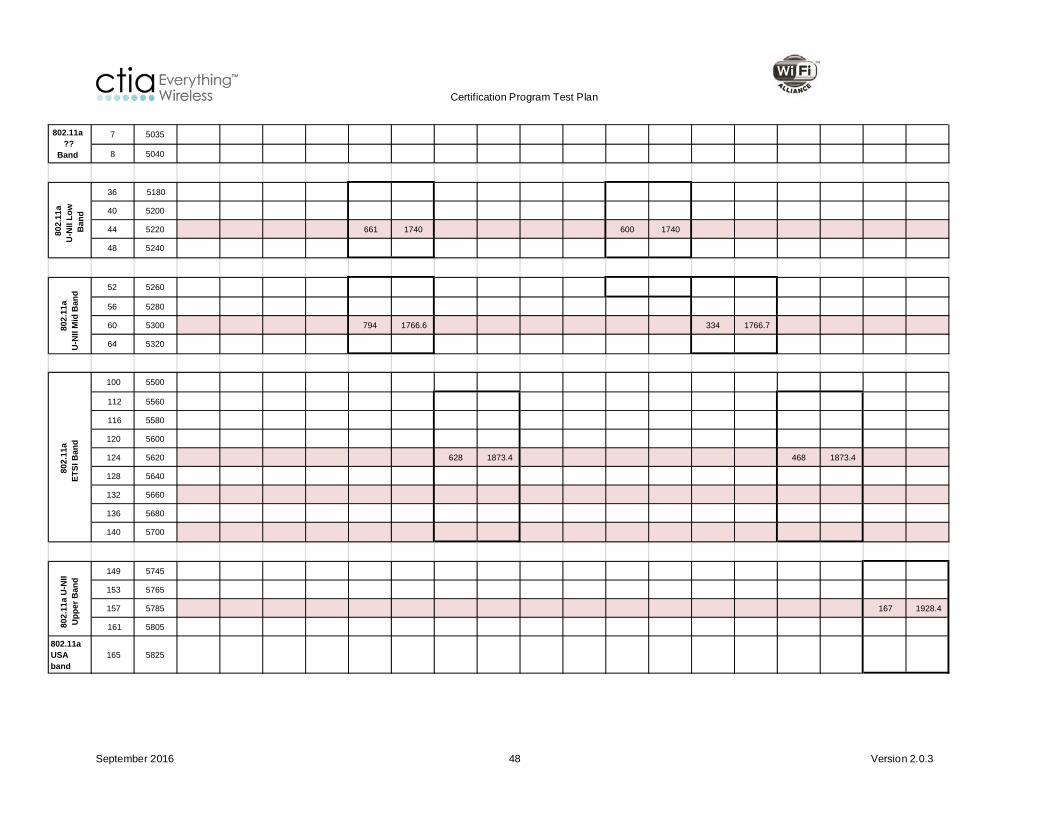
Certification Program Test Plan
September 2016 48 Version 2.0.3
7 5035
8 5040
36 5180
40 5200
44 5220 661 1740 600 1740
48 5240
52 5260
56 5280
60 5300 794 1766.6 334 1766.7
64 5320
100 5500
112 5560
116 5580
120 5600
124 5620 628 1873.4 468 1873.4
128 5640
132 5660
136 5680
140 5700
149 5745
153 5765
157 5785 167 1928.4
161 5805
802.11a USA band
165 5825
802.11a ??
Band
802.
11a
U-N
II Lo
w
Ban
d
802.
11a
U-N
II M
id B
and
802.
11a
ETSI
Ban
d80
2.11
a U
-NII
Upp
er B
and

Certification Program Test Plan
September 2016 49 Version 2.0.3
Band Edges
1920 1980 1852.4 1907.6 1710 1785 1712.4 1752.6 826.4 846.6 882.4 912.6 1925 1975 1855 1905 1715 1780
2112.4 2167.1 1932.4 1987.6 2112.4 2152.6 2112.4 2152.6 871.4 881.6 927.4 957.6 2115 2165 1935 1985 1810 1875
Chan Freq Chan Freq Chan Freq Chan Freq Chan Freq Chan Freq Chan Freq Chan Freq Chan Freq Chan Freq
1 2412
2 2417
3 2422
4 2427
5 2432
6 2437
7 2442
8 2447
9 2452
10 2457
11 2462 4357 826.4
12 2467
13 2472 4357 826.4
14 2484 4365 828
802.
11b/
g/n
Special setup
Desensitization of Wi-Fi Rx by Cellular Tx Uplink
10 MHz Tx BW, 12 RBs
10 MHz Tx BW, 12 RBs
Uplink Freq
Downlink Freq
10 MHz Tx BW, 12 RBs
Call setup defined in reference document
CTIA Test Plan [1] Appendix M
CTIA Test Plan [1] Appendix M
CTIA Test Plan [1] Section 5.8
CTIA Test Plan [1] Appendix M
CTIA Test Plan [1] Appendix M
CTIA Test Plan [1] Section 5.7
CTIA Test Plan [1] Appendix M
CTIA Test Plan [1] Section 5.7
CTIA Test Plan [1] Section 5.7
Suggested alternate name
EU, As ia , Middle East, Africa ,
Austra l ia
North America , South America ,
As iaEU, As ia
North America , South America
LTE Band 3
Region
WCDMA 3GPP Band II I
WCDMA 2100/1700 3GPP Band IV
WCDMA 850 3GPP Band V
WCDMA 3GPP Band VIII
LTE Band 1 LTE Band 2WCDMA 3GPP
Band IWCDMA 1900 3GPP Band II
RAT
EU, As ia , South America , Middle East, Austra l ia ,
Africa
Japan , EU, Middle East,
Africa , Austra l ia
North America , South America
As ia , EU, Middle East, Africa ,
Austra l ia
North America , South America , As ia , Austra l ia

Certification Program Test Plan
September 2016 50 Version 2.0.3
7 5035
8 5040
36 5180
40 5200
44 5220 1300 1740 1675 1740 19500 1740
48 5240
52 5260
56 5280
60 5300 1433 1766.6 19766 1766.6
64 5320
100 5500
112 5560
116 5580
120 5600
124 5620 9767 1873.4 18832 1873.2
128 5640
132 5660
136 5680
140 5700
149 5745
153 5765
157 5785 10592 1928.4 18082 1928.2
161 5805802.11a USA band
165 5825
802.11a ?? Band
802.
11a
U-N
II Lo
w
Band
802.
11a
U-N
II M
id B
and
802.
11a
ETSI
Ban
d80
2.11
a U
-NII
Upp
er B
and

Certification Program Test Plan
September 2016 51 Version 2.0.3
Band Edges
1715 1750 829 844 2505 2565 895 920 704 711 782 782 793 793 709 711 837 857 1852.5 1912.5
2115 2150 874 889 2625 2685 930 955 734 741 751 751 763 763 739 741 796 816 1932.5 1992.5
Chan Freq Chan Freq Chan Freq Chan Freq Chan Freq Chan Freq Chan Freq Chan Freq Chan Freq Chan Freq Chan Freq
1 2412
2 2417
3 2422
4 2427
5 2432
6 2437
7 2442
8 2447
9 2452
10 2457
11 2462 20450 825.6
12 2467
13 2472 20450 825.6
14 2484 20450 825.6
Desensitization of Wi-Fi Rx by Cellular Tx Uplink
Uplink Freq
Downlink Freq
Black boxes indicate Wi-Fi Rx vulnerability due to Cellular uplink Tx
802.
11b/
g/n
10 MHz Tx BW, 12 RBs
5 MHz Tx BW, 8 RBs
Special setup10 MHz Tx BW, 12
RBs10 MHz Tx BW, 12
RBs20 MHz Tx BW, 18
RBs10 MHz Tx BW, 12
RBs5 MHz Tx BW, 8
RBs10 MHz Tx BW, 12
RBs10 MHz Tx BW, 12
RBs10 MHz Tx BW, 12
RBs
CTIA Test Plan [1] Section 5.8
CTIA Test Plan [1] Section 5.8
CTIA Test Plan [1] Section 5.8
CTIA Test Plan [1] Section 5.8
CTIA Test Plan [1] Appendix M
CTIA Test Plan [1] Section 5.8
CTIA Test Plan [1] Section 5.8
CTIA Test Plan [1] Section 5.8
CTIA Test Plan [1] Section 5.8
CTIA Test Plan [1] Appendix M
E-UTRA Band 20
North AmericaEU, Middle East,
AfricaNorth AmericaRegion
North America , South America
North America , South America , As ia , Austra l ia
North America , EU, As ia , Middle
East, Africa , EU, As ia North America North America North America
LTE Band 25LTE Band 13
Note: only one channel , 23230
LTE Band 14
Note: only one channel , 23330
LTE Band 17 LTE Band 20LTE Band 12
Call setup defined in reference document
RAT LTE Band 4 LTE Band 5 LTE Band 7 LTE Band 8
Suggested alternate name E-UTRA Band 5

Certification Program Test Plan
September 2016 52 Version 2.0.3
7 5035
8 5040
36 5180
40 5200
44 5220 20250 1740
48 5240
52 5260
56 5280
60 5300
64 5320
100 5500
112 5560
116 5580
120 5600
124 5620 18832 1873.2
128 5640
132 5660
136 5680
140 5700
149 5745
153 5765
157 5785
161 5805
802.11a USA band
165 5825
802.11a ?? Band
802.
11a
U-N
II Lo
w
Band
802.
11a
U-N
II M
id B
and
802.
11a
ETSI
Ban
d80
2.11
a U
-NII
Upp
er B
and

Certification Program Test Plan
September 2016 53 Version 2.0.3
Band Edges
2570 2620 1880 1920 2300 2400 2496 2689.9 2010 2025 1880 1890 1890 1898.4
2570 2620 1880 1920 2300 2400 2496 2689.9 2010 2025 1880 1890 1890 1898.4
Chan Freq Chan Freq Chan Freq Chan Freq Chan Freq Chan Freq Chan Freq Chan Freq
1 2412
2 2417
3 2422
4 2427
5 2432
6 2437
7 2442
8 2447
9 2452
10 2457
11 2462
12 2467
13 2472
14 2484
Desensitization of Wi-Fi Rx by Cellular Tx Uplink
Uplink Freq
Downlink Freq
802.
11b/
g/n
20 MHz Tx BW, 18 RBs
20 MHz Tx BW, 18 RBs
Special setup20 MHz Tx BW, 18
RBs20 MHz Tx BW, 18
RBs
Suggested alternate name
Call setup defined in reference document
CWG Appendix C CWG Appendix CCTIA Test Plan [1]
Section 5.8 CWG Appendix C CWG Appendix C CWG Appendix C CWG Appendix C
ChinaEU, As ia , Middle
EastRegion
LTE Band 39 LTE Band 40 LTE Band 41 TD-SCDMA Band ATD-SCDMA Band
F1TD-SCDMA Band
F2LTE Band 38RAT
As iaAs ia , Austra l ia ,
Middle East, Africa
North America , As ia
China China

Certification Program Test Plan
September 2016 54 Version 2.0.3
7 5035
8 5040
36 5180
40 5200
44 5220 38150 2610 38150 2610
48 5240
52 5260
56 5280
60 5300 41190 2650
64 5320
100 5500
112 5560
116 5580
120 5600
124 5620
128 5640 9404 1880.4
132 5660 9436 1887.2
136 5680 9468 1893.6
140 5700 19100 1900 9492 1898.4
149 5745 36150 1915
153 5765
157 5785
161 5805802.11a USA band
165 5825
802.
11a
U-N
II Lo
w
Band
802.
11a
U-N
II M
id B
and
802.
11a
ETSI
Ban
d80
2.11
a U
-NII
Upp
er B
and
802.11a ?? Band

Certification Program Test Plan
September 2016 55 Version 2.0.3
Appendix G Change History
Version Date Comments
1.0 08-Aug-2006 Document Approved
1.1 20-Aug-2007 • Updated Purpose and References sections
• Clarified text and added footnote in Radiated RF Tests nomenclature section
• Clarified text in Minimum Measurement Distance section
• Clarified testing conditions for cellular inactive state
• Corrected step reference in step 14 of Receive Sensitivity Measurement. Removed repeated text.
• Removed reference to CTIA website for traffic generator software download
• Corrected step 1 and clarified language in step 9 regarding antenna connection in WLAN Access Point Testing Methodology section
• Removed requirement for OFMD transmit mask test on Mobile Stations and Access Points
• Updated WLAN Test Set Estimated Signal Level tables
• Added Sample Summation test report table
• Corrected title on Test 5.2.2. and 6.2.2 test report table
• Added text to clarify that Wi-Fi desense testing is done in free-space only
• Clarified that cellular desense testing is done in free-space only, and to perform reference measurements if not previously done
• Removed references to specific test equipment from document
1.2 26-June-2008 • 5 GHz TRP, TIS, & Reference Measurement frequency changes – Sections 5.1.1.2, 5.1.2.2, 5.2.1.2, 5.2.2.2, Table 5.2 5, 6.1.1.2, 6.1.2.2, 6.2.1.2, 6.2.2.2, Table B2 , Table B3, Table B4, Table B5, Table B6, Table B7, New Appendix D
• Other sections changed: Table B1 - CID Added, section 1.4 - CTIA Reference updated, Table A1 Channel change UTRA FDD Band I - IV, 4120/824.0 changed to 4132/826.4, Table B3 Reference changed from (2) to (1), Table 5.1.1 and table 6.1.1 - removed "Check Tx Mask" from comments column
1.3 01-June-2009 • Added footnote to Section 2.1, 2nd sentence.
• Added text to Section 4.1, 2nd sentence.
• Added CTIA Request # to Appendix B table.
• Added Appendix E Device Capabilities Testing Matrix
2.0 27-Feb-2015 • Added 802.11n
• Added LTE and TD-SCDMA protocols
• Updated cellular and Wi-Fi desense sections

Certification Program Test Plan
September 2016 56 Version 2.0.3
Version Date Comments
• Updated Appendix B Device Capabilities Test Matrix, removed right head and added right and left hand phantoms
• Added Appendix C – Radio Access Technologies that require testing, but are not covered in the CTIA Test Plan.
• Added Appendix D - Notebook and Tablet PC Requirements
• Added Appendix E - WLAN-LTE emulator test equipment notes when testing EUTs that support LTE band 40 or 41 (Informative)
• Added Appendix F - Table of Wi-Fi Radio channels interfered by cellular radio harmonics
• Revised Wi-Fi test procedure Sections 3.1, 4.1, 4.2 & 4.3
• Updated the Acknowledgements list
• Updated Section 4.1.3 Measurement Frequencies for Radiated tests
• Updated Table 2 parameters
• Split Table 3 to Table 3 and Table 4 for Tx and Rx and also changed Rx parameters
• Updated Section 2.1
• Replaced WLAN with Wi-Fi thought out the document as appropriate
• Revised Section 2.2 to specify PING as the primary mode for packet generation
• Revised Tables 17 and 18 to replace DER with Pass/Fail info on Intermediate Channels
• Updated title and introduction text of Appendix A
• Updated Table 12 consistent with the test case requirements of Section 4.6 and 4.17
• Updated Appendix F to include Wi-Fi desensitization matrix
• Reference Polarization columns added to all Appendix A tables that include Reference Position information
2.0.1 01-July-2015 • Modified document reference in 5th paragraph of Section 2.2.
• Updated RAT Channel Number and RAT Uplink Frequency columns in Table 4-5
• Updated channel for UNII Low, Middle and Upper Bands in Table A-5 and Table A-6.
• Deleted first sentence of Appendix A.3.
• Added text to section 1.6.2.
• Removed stray text in Table A-2.
• Fixed cross-references
2.0.2 07-Oct-2015 • “Draft 1” removed from the footnote
• Publication and footnote dates updated based on CTIA format

Certification Program Test Plan
September 2016 57 Version 2.0.3
Version Date Comments
• Tables A-7 and A-8 modified to include a field for Lab comments on maximum EIS
• Modified Section 2.2 to provide explicit guidelines for PING method for 802.11n
• Applied other purely editorial changes to the titles in Appendices sections and tables
• Removed “(WI-FI U-NII MIDDLE BAND)” from the titles and references to Channel 60 in Tables A-10 and A-12
• Requirement for usage of Hand Phantoms is clarified in Appendix B
2.0.3 30-Sept-2016 • Modified Appendix B text regarding usage of Hand Phantoms.
• Added reference table for Wi-Fi radio desensitization by closest cellular uplink frequency in Section 4.2.4. Examples corrected.
• Updated CTIA logo and WFA logo.
• Applied purely editorial correction throughout document.
• Applied changes to Section 2.1 regarding adaptive power control and regulatory domain (country code) setting.
• Applied further modifications to Section 4.2.4.
• Updated Table numbering in Section 4.
• Table B-1 modified to cover testing applicability for devices with and without WWAN simultaneous operation capability.
• Applied purely editorial changes to Sections 4.2.4 and 4.2.5.
• Clarification made in Section 3.1.5 regarding traffic generation.
• Table B-1 was reformatted without change in the content.
• Corrected Item 44.6 LTE Band 38 Channel Number and some references in Table 4-6.
• Editorial changes applied throughout document.
• References in Section 4.1 was updated/corrected.
• Applied further corrections to Table 4-6.
• Updated Appendix F.
• Updated Acknowledgement table.