test and prove deenergised
TRANSCRIPT

Business Procedure
WRITTEN BY: Dave Lavender
ENDORSED/CHECKED BY: Peter Cox / Neale Fredericks / Douglas Mukupe
APPROVED BY: Kriss Ussher
Doc No: ASM-PROC-ENG-MAN-10 Revision No: 2 Revision Date: 12.11.2020 Page: 1 of 17 THIS DOCUMENT IS UNCONTROLLED IN HARD COPY FORMAT
Test and Prove De-energised Procedure Document Number – ASM-PROC-ENG-MAN-10 This document applies to the following sites:
Brisbane Office Tarong Site
Barron Gorge Hydro PS Kareeya Hydro PS Mica Creek PS
Koombooloomba Hydro PS Swanbank PS Mackay Gas Turbine
Wivenhoe Small Hydro PS Stanwell PS Meandu Mine
Table of Contents 1.0 Purpose ........................................................................................................................................... 2 2.0 Scope ............................................................................................................................................... 2 3.0 Duty/Responsibilities ....................................................................................................................... 2 4.0 Functional Flowchart ....................................................................................................................... 3 5.0 Training and Competency ............................................................................................................... 5 6.0 Hazards and Risk Assessment ....................................................................................................... 5 7.0 Testing to Prove De-energised Frequency ...................................................................................... 5 8.0 General Test to Prove De-Energised requirements ........................................................................ 6 9.0 Alternate process to achieve test & prove de-energised on specific apparatus ............................. 6 10.0 Equipment Selection ........................................................................................................................ 7 11.0 Test and Prove De-energised Procedures ...................................................................................... 7 12.0 Review, Consultation & Communication ....................................................................................... 12 13.0 References .................................................................................................................................... 12 14.0 Definitions ...................................................................................................................................... 13 15.0 Revision History ............................................................................................................................. 14 16.0 Appendix ........................................................................................................................................ 14
16.1 Appendix 1 Testing Devices and Proving Units ............................................................................ 14

Doc No: ASM-PROC-ENG-MAN-10 Rev: 2 Rev Date: 12.11.2020 Page 2 of 17 THIS DOCUMENT IS UNCONTROLLED IN HARD COPY FORMAT
1.0 Purpose This procedure shall set out the minimum requirements for performing Test to Prove De-energised on electrical equipment at Stanwell Corporation Limited (SCL) generating sites. It is also intended to ensure compliance with the Electrical Safety Act 2002, Regulation 2013 and the code of practice for Managing of Electrical risks in the Workplace 2013.
2.0 Scope Implementation of this procedure is limited to trained and authorised personnel who perform Test to Prove De-energised as part of Safe Work System procedures, and performance of electrical work. Where Qld Legislation, Codes of practice or Australian Standards are superior to this procedure, they shall take precedence over this procedure
3.0 Duty/Responsibilities A person may hold more than one duty\responsibility under this procedure.
• Stanwell Corporation shall ensure that before electrical work is carried out on electrical equipment, the equipment is tested by a competent person to prove that it is de-energised.
• Site Management Team shall ensure that resources, processes, forms, procedures and training are in place to ensure that this procedure and all relevant legislation, standards and codes of practice are complied with at all times.
• Electrical Teams are responsible for purchasing of suitable testing devices and accessories, including the registration, testing, calibration and inspection of these devices at the specified periods.
• Authorised Licenced Electrical Worker (ALEW), Authorised Electrical Person (AEP) (Engineers and Electrical Apprentices under instruction) and Authorised Non-electrical Operations Person (ANEOP) with testing competency have a duty to follow this procedure and obtain energised electrical work authorisation prior to testing.
• Training and Development shall ensure training and refresher certification is maintained and a register of personnel as authorised is kept.
• The corporate electrical safety committee is responsible for the periodic review and maintenance of this procedure.

Doc No: ASM-PROC-ENG-MAN-10 Rev: 2 Rev Date: 12.11.2020 Page 3 of 17 THIS DOCUMENT IS UNCONTROLLED IN HARD COPY FORMAT
4.0 Functional Flowchart 4.1 LV Test and Prove De-energised Flowchart

Doc No: ASM-PROC-ENG-MAN-10 Rev: 2 Rev Date: 12.11.2020 Page 4 of 17 THIS DOCUMENT IS UNCONTROLLED IN HARD COPY FORMAT
4.2 HV Test and Prove De-energised Flowchart

Doc No: ASM-PROC-ENG-MAN-10 Rev: 2 Rev Date: 12.11.2020 Page 5 of 17 THIS DOCUMENT IS UNCONTROLLED IN HARD COPY FORMAT
5.0 Training and Competency • Low Voltage: Authorised Licenced Electrical Worker (ALEW), Authorised Electrical Person (AEP)
(Engineers and Electrical Apprentices under instruction) who perform LV Test to Prove De-Energised tasks shall be trained and authorised through electrical induction module HS211 and for non-electrical operations persons (ANEOPs) HS211 and the additional training of HS147.
Recertification/refresher training of HS147 for unlicensed workers will be conducted every 2 years.
All licenced electrical contractors will be trained and authorised in the SCL process through HS211, or where approved by the site manager an industry equivalent training package approved for use on Stanwell Corporation generating sites.
• High Voltage: An Authorised Licenced Electrical Worker (ALEW) with switching authorisation is permitted
to perform test and prove de-energised in the implementation of a Switching Isolation Certificate.
An Authorised Licenced Electrical Worker (ALEW) is permitted to perform test to prove de-energised and test before you touch as a Safe Work Coordinator or working party member.
6.0 Hazards and Risk Assessment • The SCL hazard and risk assessment process will be used to assess the risk for each hazard
identified in the Test and Prove De-energised process
• Test to prove de-energised tasks are deemed to be energised electrical work, until equipment is proven to be de-energised. The energised electrical work process must be followed in addition to this procedure. (ASM-PROC-ENG-MAN-09).
• A proving unit or integral self test function should be used to confirm test instrument functionality, prior to testing the load circuit. It is not recommended to prove the test instrument on a live LV or HV bus, however this can be performed where risk assessment permits and no other suitable test is available.
• Where HV test instruments have a self test function and no proving unit is available then this self test function is deemed an acceptable confirmation test of instrument functionality.
7.0 Testing to Prove De-energised Frequency Testing to prove de-energised must be undertaken after an isolation has been affected and before work commences and as appropriate for the duration of the electrical work.
Even though the proof of de-energised may be accomplished by any number of persons at various times during the execution of their work, this does not eliminate the requirement on each individual to satisfy themselves that the part is de-energised by either witnessing or carrying out a test to prove de-energised.
As a minimum, ongoing Test Before You Touch is required as follows:
• At the start of each working day.
• On each occasion of return to isolation following energising for testing.
• On each occasion where known changes are noted that might change the status of the electrical part e.g. contamination of the equipment by water, dust or peripheral switching and plant operations, entry into a new part of the electrical equipment i.e. a switchboard or panel.
• When the work area has been left idle (unattended) for a period of time. (when electrical work has been suspended for some weeks or months and where other activities may continue, testing should be maintained on a frequency that is assessed against the risk that is present)
Doc No: ASM-PROC-ENG-MAN-10 Rev: 2 Rev Date: 12.11.2020 Page 6 of 17 THIS DOCUMENT IS UNCONTROLLED IN HARD COPY FORMAT
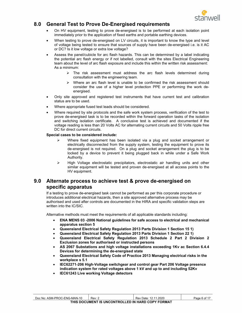
8.0 General Test to Prove De-Energised requirements • On HV equipment, testing to prove de-energised is to be performed at each isolation point
immediately prior to the application of fixed earths and portable earthing devices. • When testing to prove de-energised on LV circuits, it is important to know the type and level
of voltage being tested to ensure that sources of supply have been de-energised i.e. is it AC or DC? Is it low voltage or extra low voltage?
• Assess the panel/cubicle for arc flash hazards. This can be determined by a label indicating the potential arc flash energy or if not labelled, consult with the sites Electrical Engineering team about the level of arc flash exposure and include this within the written risk assessment: As a minimum:
The risk assessment must address the arc flash levels determined during consultation with the engineering team.
Where an arc flash level is unable to be confirmed the risk assessment should consider the use of a higher level protection PPE or performing the work de-energised.
• Only site approved and registered test instruments that have current test and calibration status are to be used.
• Where appropriate fused test leads should be considered. • Where required by site protocols and the safe work system process, verification of the test to
prove de-energised task is to be recorded within the forward operation tasks of the isolation and switching isolation certificate. A conclusive test is achieved and documented if the voltage reading is less than 20 Volts AC for alternating current circuits and 50 Volts ripple free DC for direct current circuits.
Special cases to be considered include: Where fixed equipment has been isolated via a plug and socket arrangement or
electrically disconnected from the supply system, testing the equipment to prove its de-energised is not required. On a plug and socket arrangement the plug is to be locked by a device to prevent it being plugged back in while under a Safe Work Authority.
High Voltage electrostatic precipitators, electrostatic air handling units and other similar equipment will be tested and proven de-energised at all access points to the HV equipment.
9.0 Alternate process to achieve test & prove de-energised on specific apparatus If a testing to prove de-energised task cannot be performed as per this corporate procedure or introduces additional electrical hazards, then a site approved alternative process may be authorised and used after controls are documented in the HIRA and specific validation steps are written into the IC/SIC. Alternative methods must meet the requirements of all applicable standards including:
• ENA MENS 03 -2006 National guidelines for safe access to electrical and mechanical apparatus section 5
• Queensland Electrical Safety Regulation 2013 Parts Division 1 Section 15 1) • Queensland Electrical Safety Regulation 2013 Parts Division 1 Section 22 1) • Queensland Electrical Safety Regulation 2013 Schedule 2 Part 2 Division 2
Exclusion zones for authorised or instructed persons • AS 2067 Substations and high voltage installations exceeding 1Kv ac Section 6.4.4
Devices for determining the de-energised state • Queensland Electrical Safety Code of Practice 2013 Managing electrical risks in the
workplace s 5.1 • IEC62271-206 High-Voltage switchgear and control gear Part 206 Voltage presence
indication system for rated voltages above 1 kV and up to and including 52Kv • IEC61243 Live working Voltage detectors

Doc No: ASM-PROC-ENG-MAN-10 Rev: 2 Rev Date: 12.11.2020 Page 7 of 17 THIS DOCUMENT IS UNCONTROLLED IN HARD COPY FORMAT
To validate that electrical equipment is de-energised and safe to access, each site shall document and approve each alternate process that include:
• Documenting and storing each process for site in TRIM; • Include an approved risk assessment; • Endorsed by the site electrical RPEQ; • Approval by the “Person in Charge of Electrical Equipment (Site Manager); • Communicate approved processes with Isolation / Switching Isolation Implementers; • Include all alternate test to prove de-energised steps in Isolation Certificates and Switching
Isolation Certificates during the planning of the IC/SIC; • Documenting controls within the HIRA / Safe Work Method Statement that relates to the
work task. Alternate methods to validate de-energisation and confirm equipment is safe to access, must include a combination of more than 1 method, including:
• Observation of visual breaks; • The use of panel meter and light indicators wherever installed (only used for additional
confirmation); • Use of audible proximity voltage detection instruments; • Use of fortress interlock key systems wherever installed at time of initial isolation; • Testing for de-energisation at an electrically connected Low Voltage point i.e (voltage
transformer secondaries); • Include sequenced application of Operator Earthing with a fault rated earth with
mechanical interlocking; • Voltage presence indicating system / Live line indicator.
10.0 Equipment Selection • Testing devices and leads are to be CATIII as a minimum level. • Only Test instruments approved for use on SCL sites and registered on a site electrical
equipment register are to be used. • Approved test instruments are to be inspected for damage and calibration and next test due
dates checked prior to each test. • Authorised Non-Electrical Operations Persons (ANEOP) who are trained and authorised to
perform Test and Prove De-energised procedures on low voltage circuits as part of the Safe Work System processes, are restricted to using the Fluke T5–1000 multimeter only. (Suitable for CAT III or CAT IV)
• Authorised Licenced Electrical Workers (ALEW) and Authorised Electrical Persons (AEP) (Engineers and apprentices under instruction) may select testing devices from the approved list as required to perform their job role.
11.0 Test and Prove De-energised Procedures 11.1 LV Test and Prove De-energised Procedures
11.1.1 Fluke T5-1000 (for non electrical personnel) 1. Implement controls as per HIRA or pre-approved energised electrical work SWMS. 2. Inspect the multimeter and leads for damage; check the calibration and next test due dates. Do
not use if it is damaged or past the next test due date. 3. Test DMM function; it is recommended to use a meter proving device to confirm meter function,
before resorting to using an adjacent AC & DC power supply source. 4. Go to cubicle/switchboard; stand on the hinge side of the door, face away and open panel door.
This is so that in the unlikely event of an arc flash you are not exposed. 5. Check that circuit breaker/isolator is open.
Doc No: ASM-PROC-ENG-MAN-10 Rev: 2 Rev Date: 12.11.2020 Page 8 of 17 THIS DOCUMENT IS UNCONTROLLED IN HARD COPY FORMAT
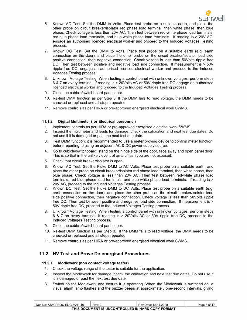
6. Known AC Test: Set the DMM to Volts. Place test probe on a suitable earth, and place the other probe on circuit breaker/isolator red phase load terminal, then white phase, then blue phase. Check voltage is less than 20V AC. Then test between red-white phase load terminals, red-blue phase load terminals, and blue-white phase load terminals. If reading is > 20V AC, engage an authorised licenced electrical worker and proceed to the Induced Voltages Testing process.
7. Known DC Test: Set the DMM to Volts. Place test probe on a suitable earth (e.g. earth connection on the door), and place the other probe on the circuit breaker/isolator load side positive connection, then negative connection. Check voltage is less than 50Volts ripple free DC. Then test between positive and negative load side connection. If measurement is > 50V ripple free DC, engage an authorised licenced electrical worker and proceed to the Induced Voltages Testing process.
8. Unknown Voltage Testing. When testing a control panel with unknown voltages, perform steps 6 & 7 on every terminal. If reading is > 20Volts AC or 50V ripple free DC engage an authorised licenced electrical worker and proceed to the Induced Voltages Testing process.
9. Close the cubicle/switchboard panel door. 10. Re-test DMM function as per Step 3. If the DMM fails to read voltage, the DMM needs to be
checked or replaced and all steps repeated. 11. Remove controls as per HIRA or pre-approved energised electrical work SWMS.
11.1.2 Digital Multimeter (for Electrical personnel) 1. Implement controls as per HIRA or pre-approved energised electrical work SWMS. 2. Inspect the multimeter and leads for damage; check the calibration and next test due dates. Do
not use if it is damaged or past the next test due date. 3. Test DMM function; it is recommended to use a meter proving device to confirm meter function,
before resorting to using an adjacent AC & DC power supply source. 4. Go to cubicle/switchboard; stand on the hinge side of the door, face away and open panel door.
This is so that in the unlikely event of an arc flash you are not exposed. 5. Check that circuit breaker/isolator is open. 6. Known AC Test: Set the Fluke DMM to AC Volts. Place test probe on a suitable earth, and
place the other probe on circuit breaker/isolator red phase load terminal, then white phase, then blue phase. Check voltage is less than 20V AC. Then test between red-white phase load terminals, red-blue phase load terminals, and blue-white phase load terminals. If reading is > 20V AC, proceed to the Induced Voltages Testing process.
7. Known DC Test: Set the Fluke DMM to DC Volts. Place test probe on a suitable earth (e.g. earth connection on the door), and place the other probe on the circuit breaker/isolator load side positive connection, then negative connection. Check voltage is less than 50Volts ripple free DC. Then test between positive and negative load side connection. If measurement is > 50V ripple free DC, proceed to the Induced Voltages Testing process.
8. Unknown Voltage Testing. When testing a control panel with unknown voltages, perform steps 6 & 7 on every terminal. If reading is > 20Volts AC or 50V ripple free DC, proceed to the Induced Voltages Testing process.
9. Close the cubicle/switchboard panel door. 10. Re-test DMM function as per Step 3. If the DMM fails to read voltage, the DMM needs to be
checked or replaced and all steps repeated. 11. Remove controls as per HIRA or pre-approved energised electrical work SWMS.
11.2 HV Test and Prove De-energised Procedures
11.2.1 Modiewark (non contact voltage tester) 1. Check the voltage range of the tester is suitable for the application. 2. Inspect the Modiewark for damage; check the calibration and next test due dates. Do not use if
it is damaged or past the next test due date. 3. Switch on the Modiewark and ensure it is operating. When the Modiewark is switched on, a
visual alarm lamp flashes and the buzzer beeps at approximately one-second intervals, giving

Doc No: ASM-PROC-ENG-MAN-10 Rev: 2 Rev Date: 12.11.2020 Page 9 of 17 THIS DOCUMENT IS UNCONTROLLED IN HARD COPY FORMAT
clear standby indication and that the instrument is operational. Do not use if this indication is not present.
4. When a Modielive is available, prove the tester works by holding the Modielive proving unit test probe near, but not touching the Modiewark. Indication that a circuit is energised occurs if the audible and visual alarms change to continuous operation i.e. a steady light and continuous sounding buzzer. If it doesn’t change the tester needs to be checked or replaced.
5. Implement controls as per HIRA or pre-approved energised electrical work SWMS, including wearing of appropriate arc flash and electric shock PPE.
6. Check that circuit breaker/isolator is open and racked out. 7. Select the correct voltage range for the circuit being tested. 8. Test the circuit by holding the probe close to each phase in turn on the load/circuit side of the
device to be tested. In each case check the tester does not light up or sound the buzzer. If it does, stop and investigate the cause.
9. Repeat step 3 and 4 to retest the tester. If it doesn’t have an audible and visual alarm, the tester needs to be checked or replaced and all steps repeated.
10. Remove controls as per HIRA or pre-approved energised electrical work SWMS.
11.2.2 Taplin Tester 1. Check the voltage range of the tester is suitable for the application. 2. Inspect the Taplin Tester for damage; check the calibration and next test due dates. Do not use
if it is damaged or past the next test due date. 3. Type D100: Connect interconnecting lead between probes. Insert probe with meter into the self
test unit receptacle and the second probe onto the raised contact on the test unit. Push down on the probe with the meter and note deflection on the meter of approximately 20% and that the red test lamp is lit. Do not use if this indication is not present.
4. Type D225/M: Switch the Taplin tester selector switch to “PD’ or self test position. Using bare hands place one hand on the metal of the dial indicator and the other on the test probe of the tester. The dial indicator will deflect between 200 and 370 indicating that the tester is operating. Do not use if this indication is not present.
5. Implement controls as per HIRA or pre-approved energised electrical work SWMS, including wearing of appropriate arc flash and electric shock PPE.
6. Check that circuit breaker/isolator is open and racked out. 7. Select the correct voltage range for the circuit being tested. 8. Touch the probe on each phase in turn on the load/circuit side of the device to be tested. In
each case check the tester does not indicate voltage on the dial indicator. If it does, stop and investigate the cause.
9. Repeat step 3 or 4 to retest the tester. If it doesn’t indicate correctly, the tester needs to be checked or replaced and all steps repeated.
10. Remove controls as per HIRA or pre-approved energised electrical work SWMS.
11.2.3 CATU CC-245-275.330 Voltage Detector 1. Check the voltage range of the tester is suitable for the application. 2. Inspect the CATU Voltage Detector and link sticks for damage; check the calibration and next
test due dates. Do not use if it is damaged or past the next test due date. 3. Press the test button on the voltage detector and ensure it is operating. Correct working of the
detector is indicated by the red diode(s) flashing and an audible buzzer sounding. When the test button is released the red diode(s) go out and the green diode(s) light up for approximately 1-2 minutes, the audible buzzer sound also ceases. Do not use if this indication is not present.
4. Implement controls as per HIRA or pre-approved energised electrical work SWMS, including wearing of appropriate arc flash and electric shock PPE.
5. Check that circuit breaker/isolator is open and racked out. 6. Next touch the probe on each phase in turn on the load/circuit side of the device to be tested. In
each case check the green diode(s) stays on. If the red diode(s) comes on and/or the audible buzzer sounds, stop and investigate the cause.
7. Repeat step 3 and 4. If the red diode(s) and audible buzzer doesn’t activate, the tester needs to be checked or replaced and all steps repeated.

Doc No: ASM-PROC-ENG-MAN-10 Rev: 2 Rev Date: 12.11.2020 Page 10 of 17 THIS DOCUMENT IS UNCONTROLLED IN HARD COPY FORMAT
8. Remove controls as per HIRA or pre-approved energised electrical work SWMS.
11.2.4 Fameca TAG2020 Voltage Detector 1. Check the voltage range of the tester is suitable for the application. 2. Inspect the Fameca Voltage Detector and link sticks for damage; check the calibration and next
test due dates. Do not use if it is damaged or past the next test due date. 3. Press the red test button on the voltage detector and ensure it is operating. When it is switched
on the red diode flashes and there is also an audible signal tone given off. When the test button is released the red diode goes out and the green diode lights up for approximately 2 minutes, the audible tone also ceases. Do not use if this indication is not present.
4. When a Fameca PT-DET tester is available, Confirm operation of Fameca Voltage Detector using the Fameca PT-DET Tester proving unit.
5. Implement controls as per HIRA or pre-approved energised electrical work SWMS, including wearing of appropriate arc flash and electric shock PPE.
6. Check that circuit breaker/isolator is open and racked out. 7. Next touch the probe on each phase in turn on the load/circuit side of the device to be tested. In
each case check the green diode stays on. If the red diode comes on, stop and investigate the cause.
8. Repeat step 3 and 4. If the red diode and audible signal don’t activate, the tester needs to be checked or replaced and all steps repeated.
9. Remove controls as per HIRA or pre-approved energised electrical work SWMS.

Doc No: ASM-PROC-ENG-MAN-10 Rev: 2 Rev Date: 12.11.2020 Page 11 of 17 THIS DOCUMENT IS UNCONTROLLED IN HARD COPY FORMAT
11.3 Induced Voltages Test Procedure NOTE: This procedure is to be performed by an SCL Authorised Licensed Electrical Worker only. The principle behind this test is to determine if a sustained voltage remains present or is an induced voltage. Testing is performed between each phase and earth.
1. This procedure can only be used when the measured voltage is extra low voltage:
i. Less than 50 volts AC; or ii. Less than 120 volts DC.
Note: If the measured voltage is greater than i or ii, refer to the Electrical Engineering team
for further investigation.
2. Connect a resistance of 20 kΩ in parallel with the voltmeter when measuring the voltage.
Note: This is done to place a load in the circuit to check if the source voltage is sustained at this load.
Shunts are commercially available from MRD Rail Technologies Pty Ltd
3. If measuring AC voltage and the sustained voltage is above 20V AC, proceed to Step 5. 4. If measuring DC voltage and the sustained voltage is above 50V DC, proceed to Step 5. 5. If an acceptable test is not obtained then reduce the resistance to 3kΩ and repeat the test.
Note: This places a higher load in the circuit to determine if the source voltage is sustained
at this lower resistance.
6. If the sustained voltage remains above 20V AC or 50V DC then the circuit is to be considered as not proven de-energised – proceed to Step 7.
7. Report any instances of circuits not being able to be proven de-energised to an Electrical
RPEQ immediately so that further investigation can be conducted into the cause.
11.4 Managing Induced Voltages 1. Where induced voltages can not be controlled by other means they will be managed by the
introduction of a grounding strap, connected between all phases of the circuit and earth for the duration of the electrical works. The position of the grounding strap will be as close as practical to the work area. The use of grounding straps will be approved by an Electrical RPEQ.
Note: The grounding strap must be recorded on the Safe Work Authority and removed before the Safe Work Authority is surrendered.
Multimeter
R
Conductor
Doc No: ASM-PROC-ENG-MAN-10 Rev: 2 Rev Date: 12.11.2020 Page 12 of 17 THIS DOCUMENT IS UNCONTROLLED IN HARD COPY FORMAT
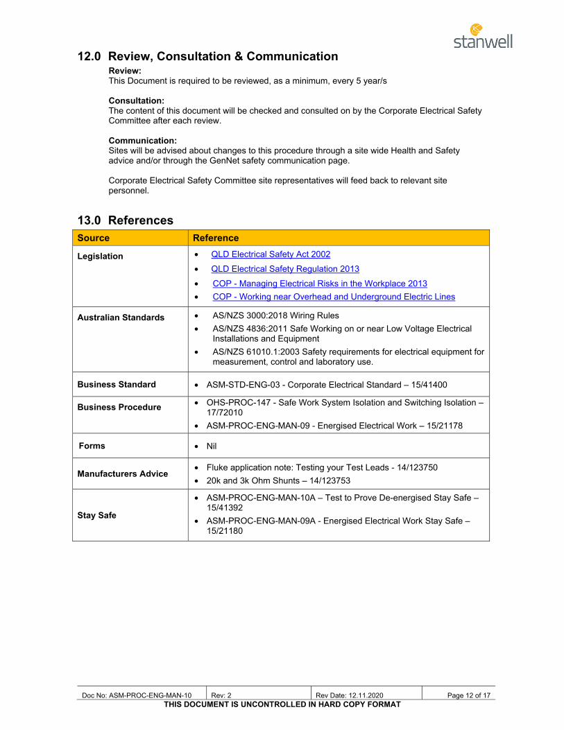
12.0 Review, Consultation & Communication Review: This Document is required to be reviewed, as a minimum, every 5 year/s Consultation: The content of this document will be checked and consulted on by the Corporate Electrical Safety Committee after each review. Communication: Sites will be advised about changes to this procedure through a site wide Health and Safety advice and/or through the GenNet safety communication page. Corporate Electrical Safety Committee site representatives will feed back to relevant site personnel.
13.0 References Source Reference
Legislation • QLD Electrical Safety Act 2002 • QLD Electrical Safety Regulation 2013 • COP - Managing Electrical Risks in the Workplace 2013 • COP - Working near Overhead and Underground Electric Lines
Australian Standards • AS/NZS 3000:2018 Wiring Rules • AS/NZS 4836:2011 Safe Working on or near Low Voltage Electrical
Installations and Equipment • AS/NZS 61010.1:2003 Safety requirements for electrical equipment for
measurement, control and laboratory use.
Business Standard • ASM-STD-ENG-03 - Corporate Electrical Standard – 15/41400
Business Procedure • OHS-PROC-147 - Safe Work System Isolation and Switching Isolation – 17/72010
• ASM-PROC-ENG-MAN-09 - Energised Electrical Work – 15/21178
Forms • Nil
Manufacturers Advice • Fluke application note: Testing your Test Leads - 14/123750 • 20k and 3k Ohm Shunts – 14/123753
Stay Safe
• ASM-PROC-ENG-MAN-10A – Test to Prove De-energised Stay Safe – 15/41392
• ASM-PROC-ENG-MAN-09A - Energised Electrical Work Stay Safe – 15/21180

Doc No: ASM-PROC-ENG-MAN-10 Rev: 2 Rev Date: 12.11.2020 Page 13 of 17 THIS DOCUMENT IS UNCONTROLLED IN HARD COPY FORMAT
14.0 Definitions Term Meaning
Arc Flash
Arc Flash is the result of a rapid release of energy due to an arcing fault between a phase bus bar and another phase bus bar, neutral or a ground. During an arc fault the air is the conductor. As a consequence, a person in proximity to such an arc flash can be injured. This rapid release of energy can be accompanied by a blast.
Arc Flash Protection Boundary
An approach limit at a distance from live parts that are uninsulated or exposed within which a person could receive a second degree burn. (IEEE1584:2002 Clause 3.13).
Arc Rated Clothing Means clothing that has an ATPV rating
ATPV: Means Arc Thermal Performance Value
A reported value from electric arc testing. This value is presented in calories per square centimetre and represents the maximum capability for arc-flash protection of a particular garment, fabric or item of arc flash PPE.
Authorised Electrical Person (AEP)
A person who is not required to hold an electrical licence for the performance of their profession as an Electrical Engineer or calling as an, Electrical Apprentice, Electrical Trainee/Student Authorisation is granted after completion of relevant training (including Electrical Safety Induction, annual resus and LV rescue, and any other necessary training.
Authorised Licensed Electrical Worker (ALEW)
A person who is the holder of a Queensland electrical workers license (or equivalent). SCL authorises Licensed Electrical workers after completion of relevant training (including Electrical Safety Induction, annual Resus and LV rescue, and any other necessary training.
Authorised Non Electrical Person (ANEP)
A person who is not an ALEW or AEP and is required to vary their LV exclusion zone as part of their work. For example Isolating officer, Safe Work Coordinator, Safety observer etc.
Competent Having acquired the knowledge and skills enabling that person to perform the task required, in a safe and effective manner.
DC Direct current
DMM Digital Multimeter
Electrical Equipment
Any apparatus, appliance, cable, conductor, fitting, insulator, material, meter or wire: Used for controlling, generating, supplying, transforming or transmitting
electricity at a voltage greater than extra low voltage: Operated by electricity at a voltage greater than extra low voltage; That is or forms part of, a cathodic protection system.
Energised Electrical Work Guide
Document listing all controls that are required when performing any live electrical work, as required under the Electrical Safety Act 2002
Extra Low Voltage (ELV) Voltage of 50V or less AC RMS, or 120V or less ripple-free DC “(QLD Electrical Act 2002 - Schedule 2)”
Exposed Part is any terminal, connection, conductor or electrical part that can be contacted with a standard test finger
Flame Retardant Clothing
Clothing that has properties which suppress or delay the combustion or propagation of flame.
High Voltage (HV) Voltage exceeding 1000 volts AC or 1500 volts ripple-free DC
Induced Voltage
A voltage due to electromagnetic or capacitive coupling that may be present in an isolated conductor if it is located near to or run in parallel with an energised conductor
Doc No: ASM-PROC-ENG-MAN-10 Rev: 2 Rev Date: 12.11.2020 Page 14 of 17 THIS DOCUMENT IS UNCONTROLLED IN HARD COPY FORMAT
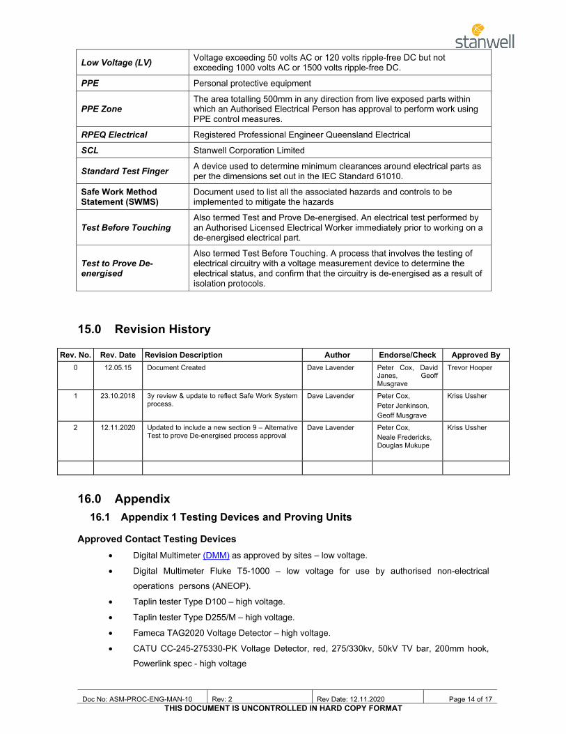
Low Voltage (LV) Voltage exceeding 50 volts AC or 120 volts ripple-free DC but not exceeding 1000 volts AC or 1500 volts ripple-free DC.
PPE Personal protective equipment
PPE Zone The area totalling 500mm in any direction from live exposed parts within which an Authorised Electrical Person has approval to perform work using PPE control measures.
RPEQ Electrical Registered Professional Engineer Queensland Electrical
SCL Stanwell Corporation Limited
Standard Test Finger A device used to determine minimum clearances around electrical parts as per the dimensions set out in the IEC Standard 61010.
Safe Work Method Statement (SWMS)
Document used to list all the associated hazards and controls to be implemented to mitigate the hazards
Test Before Touching Also termed Test and Prove De-energised. An electrical test performed by an Authorised Licensed Electrical Worker immediately prior to working on a de-energised electrical part.
Test to Prove De-energised
Also termed Test Before Touching. A process that involves the testing of electrical circuitry with a voltage measurement device to determine the electrical status, and confirm that the circuitry is de-energised as a result of isolation protocols.
15.0 Revision History
16.0 Appendix 16.1 Appendix 1 Testing Devices and Proving Units
Approved Contact Testing Devices • Digital Multimeter (DMM) as approved by sites – low voltage.
• Digital Multimeter Fluke T5-1000 – low voltage for use by authorised non-electrical
operations persons (ANEOP).
• Taplin tester Type D100 – high voltage.
• Taplin tester Type D255/M – high voltage.
• Fameca TAG2020 Voltage Detector – high voltage.
• CATU CC-245-275330-PK Voltage Detector, red, 275/330kv, 50kV TV bar, 200mm hook,
Powerlink spec - high voltage
Rev. No. Rev. Date Revision Description Author Endorse/Check Approved By 0 12.05.15 Document Created Dave Lavender Peter Cox, David
Janes, Geoff Musgrave
Trevor Hooper
1 23.10.2018 3y review & update to reflect Safe Work System process.
Dave Lavender Peter Cox, Peter Jenkinson, Geoff Musgrave
Kriss Ussher
2 12.11.2020 Updated to include a new section 9 – Alternative Test to prove De-energised process approval
Dave Lavender Peter Cox, Neale Fredericks, Douglas Mukupe
Kriss Ussher

Doc No: ASM-PROC-ENG-MAN-10 Rev: 2 Rev Date: 12.11.2020 Page 15 of 17 THIS DOCUMENT IS UNCONTROLLED IN HARD COPY FORMAT
Approved Non Contact Testing Devices • Modiewark – high voltage
Note: The use of HV testers (non contact type) that detect an electrical field surrounding an energised conductor may not be suitable for cables that are surrounded by a metallic screen or cables carrying direct current. In these cases a contact type tester is to be used.
Devices Not Approved for Testing to Prove De-energised
• Contact testers like Wiggys, Series Test Lamps, Test pencils and similar devices are not to be used as test to prove de-energised devices or for voltage detection.
• Non-contact testers like Volt sticks. Volt alert, Volt sensor and similar devices are not to be used as test to prove de-energised devices. However these devices can be used to assist with fault finding and other tasks as suitable.

Doc No: ASM-PROC-ENG-MAN-10 Rev: 2 Rev Date: 12.11.2020 Page 16 of 17 THIS DOCUMENT IS UNCONTROLLED IN HARD COPY FORMAT
Approved Proving Units (field generators, voltage sources)
• Model: PD690 Voltage Indicator Proving unit (700V AC/DC) Martindale
• Model: PRV240 Fluke meter proving unit (240V AC & DC)
• Model: SP- 200
Socket & See Voltage Indicator Proving unit (50V to 690V) (for low voltage)
• SCL Internally Manufactured Device (for low voltage)
• Model: PD240 Voltage Indicator Proving unit (240V DC only) Martindale

Doc No: ASM-PROC-ENG-MAN-10 Rev: 2 Rev Date: 12.11.2020 Page 17 of 17 THIS DOCUMENT IS UNCONTROLLED IN HARD COPY FORMAT
• Model: PT-DET Fameca TAG Tester (for high voltage)
\
• Model: Modielive Modiewark Non Contact Tester (for high voltage)
• Model: CL-1-05/06 CATU High Voltage Proving Unit