test and evaluation report of the physio control defibrillator
TRANSCRIPT

D-A234 593 USAARL Report No. 91-14
Test and Evaluation Report
of the Physlo Control Defibrillator/MonitorModel LIFEPAK10
By
Jeffrey D. Haun (Project Officer)and
Joseph R. Licina (Project Officer)
Bill Olding (UES, Inc.)
Martin Quattlebaum (UES, Inc.)
Biodynamics Research Division DTICAELECTE •
APR 19 1991'.
March 1991
Approved for public release; distribution unlimited.
91 4 17 088United States Army Aeromedical Research Laboratory
Fort Rucker, Alabama 36362-5292
Qualif ied reauesters
Qualified requesters may obtain copies from the Defense TechnicalInformation Center (DTIC), Cameron Station, Alexandria, Virginia22314. Orders will be expedited if placed through the librarianor other person designated to request documents from DTIC.
Chanae of address
Organizations receiving reports from the U.S. Army AeromedicalResearch Laboratory on automatic mailing lists should confirmcorrect address when corresponding about laboratory reports.
Disposition
Destroy this document when it is no longer needed. Do not returnit to the originator.
Disclaimer
The views, opinions, and/or findings contained in this report arethose of the author(s) and should not be construed as an officialDepartment of the Army position, policy, or decision, unless sodesignated by other official documentation. Citation of tradenames in this report does not constitute an official Departmentof the Army endorsement or approval of the use of such commercialitems.
Reviewed:
DENNIS F. SHANAHANLTC, MC, MFSDirector, Biodynamics
Research Division
Released for publication:
ROJER W. WILEY, O.D., Ph.D. DAVID H. KARNECh irinan, Scientific Colonel, MC, S SReview Committee commanding

UNCLASSIFIEDSECURITY CLASSIFICATION OF THIS PAGE
Form Approved
REPORT DOCUMENTATION PAGE OMB No. 0704-0188
Ia. REPORT SECURITY CLASSIFICATION Ib, RESTRICTIVE MARKINGS
UNCLASSIFIED .....
2a. SECURITY CLASSIFICATION AUTHORITY 3. DISTRIBUTION /AVAILABILITY OF REPORT
_Approved for public release, distribution
2b. DECLASSIFICATION I DOWNGRADING SCHEDULE unlimited
4 PERFORMING ORGANIZATION REPORT NUMBER(S) 5. MONITORING ORGANIZAr:ON REPORT NUMBER(S)
USAARL Report No. 91-14
6a. NAME OF PERFORMING ORGANIZATION 6b. OFFICE SYMBOL 7a. NAME OF MONITORING ORGANIZATION
U.S. Army Aeromedical Research (if applicable) U.S. Army Medical Research and Development
Laboratory SGRD-UAD-IE Command
6c. ADDRESS (City, State, and ZIP Code) 7b. ADDRESS (City, State, and ZIP Code)P.O. Box 577 Fort DetrickFort Rucker, AL 36362-5292 Frederick, MD 21702-5012
Ba. NAME OF FUNDING/ SPONSORING 8b. OFICE SYMBOL 9. PROCUREMENT INSTRUMENT IDENTIFICATION NUMBERORGANIZATION (if applicable)
8c, ADDRESS (City, State, and ZIP Code) 10. SOURCE OF FUNDING NUMBERS
PROGRAM PROJECT TASK WORK UNITELEMENT NO. NO. NO. ACCESSION NO.
0603807A 3M463807D8 6 LC 201
11. TITLE (Include Security Classification)
Test and Evaluation Report of the Physio Control Defibrlllator/Monitor Model LIFEPAKI& 10
12. PERSONAL AUTHOR(S)Jeffrey D. Haun, Joseph R. Licina, Bill Olding, Martin Ouattlebaum
13a. TYPE OF REPORT 13b. TIME COVERED 14. DATE OF REPORT (Year, Month, Day) 15. PAGE COUNTFinal I FROM _ TO _ 1991 March 66
16. SUPPLEMENTARY NOTATION
17. COSATI CODES 18. SUBJECT TERMS (Continue on reverse if necessary and identify by block number)FIELD GROUP SUB-GROUP Electromagnetic compatibility, test and evaluation,
Faeromedical equipment
19. ABSTRACT (Continue on reverse if necessary and identify by block number)
>rhe Physio Control Defibrillator/Monitor Model LIFEPAK® 10 was tested for electromagnetic.interference/compatibility in the UH-60A helicopter under the U.S. Army Program for Testingand Evaluation of Equipment for Aeromedical Operations. The tests were conducted using"current military and industrial standards and procedures for electromagnetic interference/compatibility and human factors. The LIFEPAK® 10 passed the overall evaluation and is
validated as compatible with U.S. Army aeromedic;ail Rircraft. .
20. DISTRIBUTION /AVAILABILITY OF ABSTRACT 21. ABSTRACT SECURITY CLASSIFICATIONSUNCLASSIFIED/UNLIMITED C3 SAME AS RPT. C3 DTIC USERS UNCLASSIFIED
22a. NAME OF RESPONSIBLE INDIVIDUAL 22b TELEPHONE (Include Area Code) 22c. OFFICE SYMBOLChief, Scientific Information Center (205) 255-6907 SGRD-UAX-SI
DD Form 1473, JUN 86 Previous editions are obsolete. SECURITY CLASSIFICATION OF THIS PAGE
U-.)b~r M7 J -
Acknowledgment
The authors would like to acknowledge the invaluable efforts ofDennis F. Shanahan, flight surgeon, USAARL; and Harold D. Moore,research aviator, USAARL, for their contributions to this report.
,• )
Accession forNTIS GRA&IDTIC TABUnannounced
I Justificatlon
ByI Distribution/
Availability CodesS[---Avail and/or;Diat Special" I

Table of contents
SECTION PAGE
1. EXECUTIVE DIGEST
1.1 Test objectives . . . . ............ . . 1-1
1.2 Testing authority ................ 1-2
* 1.3 Scope .............. ........... ........... 1-2
1.4 Material description ......... .............. 1-2
1.5 Summary . ......................... 1-3
1.6 Conclusion .................................. 1-4
2. SUBTESTS
2.1 Initial inspection .............. ............... 2-1
2.2 Battery life evaluation . . . . ........... 2-1
2.3 Electrical safety evaluation ........ .. 2-2
2.4 Human factors evaluation (laboratory) ...... 2-3
2.5 Altitude (low pressure) test ... . . . . . 2-3
2.6 Vibration test ........... ................. .. 2-4
2.7 High temperature test ........ .............. .. 2-6
2.8 Low temperature test .............. ............. 2-8
2.9 Humidity test ............ .................. .. 2-9
2.10 Electromagnetic characteristics test .. ...... .. 2-10
2.11 In-flight human factors evaluation ... ....... .. 2-11
2.12 In-flight EMI/EMC characteristics test . . . . . 2-12
3. SUPPORTING DOCUMENTATION
3.1 Detailed test information ...... ............ .. 3-1
i
Table of contents (Continued)
3.2 Test data .......... .............. ..... . . . 3-3
3.3 Criteria, significant problems, and . . . . . . . 3-41suggested improvements
3.4 References ............... ................. ... 3-44
3.5 Abbreviations . . . . . . . ............. 3-46
3.6 Distribution list ............ ................ .. 3-48
ii

Section 1. Executive digest
The Army program for Test and Evaluation of AeromedicalEquipment uses existing military standards (MIL-STD) and collec-tive professional expertise to test and evaluate selected medicalequipment proposed for use aboard Army aircraft. Equipmentmeeting these standards ensures the safety of the crew, patients,and aircraft by eliminating risks due to: (1) interference bythe medical equipment with aircraft systems/subsystems operation,(2) the aircraft system's interference with the operation of themedical equipment, (3) the medical equipment's susceptibility toenvironmental exposure, or (4) physical and/or functional incom-patibility while in use on board selected rotary-wing aircraft.This program tests both developmental and nondevelopmental (offthe shelf) medical equipment destined for use aboard Army aero-medical aircraft.
1.1 TEST OBJECTIVES
1.1.1 To determine if the medical equipment is complete andoperational per the manufacturer's operating instructions.
1.1.2 To ensure the electrical safety of the medical equipment.
1.1.3 To ensure the equipment will function as designed through-out the rated battery operation time.
1.1.4 To ensure the safety of the operator, the patient, and theaircrew.
1.1.5 To assess design considerations which potentially couldcontribute to an operator error.
1.1.6 To determine if the medical equipment can function asdesigned in a low pressure environment.
1.1.7 To determine the ability of the medical equipment to with-stand the vibrational stresses expected in a rotary-wing flightenvironment without degradation or malfunction.
1.1.8 To determine the ability of the medical equipment to bestored and operated in a high temperature environment.
1.1.9 To determine the ability of the medical equipment to bestored and operated in a low temperature environment.
1.1.10 To determine the ability of the medical equipment tooperate satisfactorily for short periods during exposure tohighly humid conditions.
i-i

1.1.11 To assess the levels of electromagnetic emissions pro-duced by the medical equipment within selected frequency ranges.
1.1.12 To assess the minimum electromagnetic susceptibilitylevels of the medical equipment within selected frequency ranges.
1.1.13 To assess the physical and/or functional compatibility ofthe medical equipment while in use on board the aircraft.
1.1.14 To assess the electromagnetic interference (EMI) andelectromagnetic compatibility (EMC) characteristics of themedical equipment with the host aircraft and its installedsystems.
1.2 TESTING AUTHORITY
Research and Technology Work Unit Summary, dated 5 October1989. Project number 3M4620)7D836, titled, Army Program forTesting and Evaluation of Equipment for Aeromedical Operations.
1.3 SCOPE
1.3.1 This test was conducted at the United States Army Aeromed-ical Research Laboratory (USAARL), Cairns Army Airfield (CAAF),and designated test flight areas in and around Fort Rucker,Alabama.
1.3.2 The USAARL UH-60A aircraft, serial number 88-26069, withsubsystems delineated in paragraph 3.2.2, was configured with thePhysio Control defibrillator/monitor, model LIFEPAKO 10 and usedas the test aircraft for the in-flight evaluation. The in-flightevaluation required 4.3 flight hours.
1.3.3 Laboratory testing was accomplished at USAARL usinggovernment furnished equipment (GFE) by Universal Energy Systems,Inc. (UES), under contract No. DAMD 17-86-C-6215.
1.3.4 Prior to flight testing, the following tests were accom-plished: Acceptance inspection, equipment training, electromag-netic compatibility, human factors and safety, environmentalcompatibility, and in-flight compatibility.
1.3.5 An airworthiness release (AWR) dated 27 December 1990 wasreceived from the U.S. Army Aviation Systems Command (AVSCOM)prior to the in-flight testing of the LIFEPAK* 10.
1.4 MATERIAL DESCRIPTION
The Physio Control LIFEPAK* 10 is a portable defibrillator,monitor, and optional noninvasive pacer. It is battery poweredand contains both a cathode ray tube (CRT) cardioscope, which
1-2

displays real time electrocardiographs (ECG), and two defibril-lator paddles which may discharge any of nine selectable energylevels.
1.5 SUMMARY
1.5.1 Laboratory testinag
1.5.1.1 Battery Life Evaluation: The LIFEPAK° 10 performedlonger than the manufacturer specification of 45 minutes ofoperation with a fully charged battery. Although no rechargetime was specified in the manufacturer's manuals, the batterieswere recharged in 90 minutes in the laboratory.
1.5.1.2 Electrical Safety Evaluation: All measurements werewithin acceptable limits. No unsafe qualities were found in theLIFEPAKO 10. The limits for currents and resistances were inaccordance with the National Fire Prevention Association (NAFP)standards.
1.5.1.3 Human Factors Evaluation: The LIFEPAK* 10 was found tobe unsatisfactory in the conductor criteria. The cables connect-ing the defibrillator paddles interfere with the replacement ofthe paddles in their storage holders. Standards referencedinclude MIL-STD-1472D, McCormick's HFE Guide, and UL-544.
1.5.1.4 Environmental Tests: The LIFEPAKO 10 can be expected toperform in a variety of environmental conditions. Its perfor-mance was found to be satisfactory in all stages of the environ-mental testing. The requirements for environmental tests areestablished in MIL-STD-810D, methods 500.2 (altitude), 514.3(vibration), 501.2 (high temperature), 502.2 (low temperature),and 507.2 (humidity).
1.5.1.5 Radiated Emissions Tests (RE02): The LIFEPAK* 10 may beunsatisfactory for use in certain EMI sensitive environments.Narrowband (NB) and broadband (BB) radiated emissions weredetected in the test frequency ranges. Some narrowband andbroadband emissions exceeded the test limits. Emission limitsare set forth in MIL-STD-461, Notice 4.
1.5.1.6 Radiated Susceptibility Test (RS03): The LIFEPAKO 10was not found to be susceptible to the radiated interferencelevels in this test. Testing was not performed in the frequencyrange 10 kHz to 200 MHz due to the "in repair status" of thetransmitter amplifier used for this range of testing.
1.5.2 In-flicht testinQ
1.5.2.1 During the in-flight human factors evaluation, theLIFEPAKO 10 was found to be satisfactory in all but two cate-
1-3

gories of the evaluation criteria. First, the human factorsdeficiency noted in the laboratory evaluation (paragraph 1.5.1.3)was exacerbated by the cramped quarters in the aircraft. Second,the inability of the flight surgeon to hear the audio alarmswhile wearing the required flight ensemble and the environmentalnoise produced by the aircraft precludes the use of the audioalarms.
1.5.2.2 The aircraft and its subsystems were not adverselyaffected by the operation of the LIFEPAKO 10 in any of the pre-scribed flight test modes.
1.5.2.3 The LIFEPAKO 10 was not affected by the aircraft and itssubsystems during the in-flight testing.
1.6 CONCLUSIONS
Based on the combination of laboratory and in-flight test-ing, the LIFEPAKe 10 is validated as compatible with U.S. Armyaeromedical UH-60A Blackhawk with the subsystems listed inparagraph 3.2.2. The LIFEPAK° 10 must be restricted to batteryuse only.
1-4

SECTION 2. SUBTESTS
2.1 INITIAL INSPECTION
2.1.1 Qkje~tixa
To determine if the LIFEPAK 10 is complete and operationalfor testing per the manufacturer's operating instructions.
2.1.2 Criteria
2.1.2.1 The physical inventory is conducted solely for investi-gation and documentation.
2.1.2.2 The LIFEPAK' 10 will display a consistent and accuratemeasurement of simulated ECG signals within + 2 percent anddeliver the programmed defibrillator energy within 1 percent.
2.1.3 Test procedure
2.1.3.1 A complete physical inventory of the LIFEPAK9 10 wascompleted per the manufacturer's equipment list.
2.1.3.2 An operational validation test of the LIFEPAKO 10 wasconducted per the manufacturer's operating instructions byUSAARL's medical maintenance personnel.
2.1.4 Test findings
2.1.4.1 The LIFEPAKO 10 was inventoried and found to be com-plete.
2.1.4.2 The LIFEPAKO 10 operated as prescribed in the manufac-
turer's operating manual P/N 805057-00. Criteria met.
2.2 BATTERY LIFE EVALUATION (Laboratory)
2.2.1 Objective
To ensure the equipment will function as designed throughoutthe rated battery operation time.
2.2.2 Criterion
Verify manufacturer's specified full power battery lifeexpectancy of 45 minutes during continuous monitoring of asimulated ECG rate of 60 beats per minute (BPM).
2-1

2.2.3 Test procedure
2.2.3.1 Charging and operation cycles were conducted in ambientroom conditions of 23 0 C, 40-60 percent relative humidity (RH).
2.2.3.2 The LIFEPAK* 10 was operated continuously using itsthree nickel-cadium (NiCad) batteries. The ECG simulator was setto 60 BPM and the CRT display was set for a 1.5 cm 'R' wavedisplay. Monitoring was continued until all three batteries weredepleted. Depletion times for individual batteries were noted.
2.2.3 Test findings
The test was conducted using three fully charged batteries.The average operating time in testing was 1 hour and 51 minutesat room temperature (759F and 55 percent RH). This exceedsmanufacturer specification. Although no recharge time wasspecified in the manufacturer's manuals, the batteries wererecharged in 90 minutes in the laboratory. Criterion met.
2.3 ELECTRICAL SAFETY EVALUATION
2.3.1 Objective
To ensure the electrical safety, by evaluation of case-to-ground resistance and case-to-ground current leakage, of theLIFEPAK® 10.
2.3.2 Criterion
The LIFEPAKX 10 shall meet the standards established inNational Fire Protection Association (NFPA) 99 for electricalsafety of medical equipment.
2.3.3 Test procedure
Measurements in the electrical safety evaluation were made,with a Neurodyne-Dempsey model 431F electrical safety analyzer,in accordance with the procedures described in Technical Bulletin(TB) Number 38-750-2. Case-to-ground resistance and variouscase-to-ground leakage currents were measured. Leakage currentswere measured using a 10 by 20 centimeter aluminum foil sheettaped flush to the equipment case. Checks were made for safetyconcerns such as case integrity, breaks in power cord insulation,and connectors.
2.3.4 Test findings
Grounding conductor resistance was 41.3 milliohms andmaximum case leakage current was 11.6 microamperes. Measurementswere taken only on the battery charger unit for the LIFEPAKX 10.
2-2
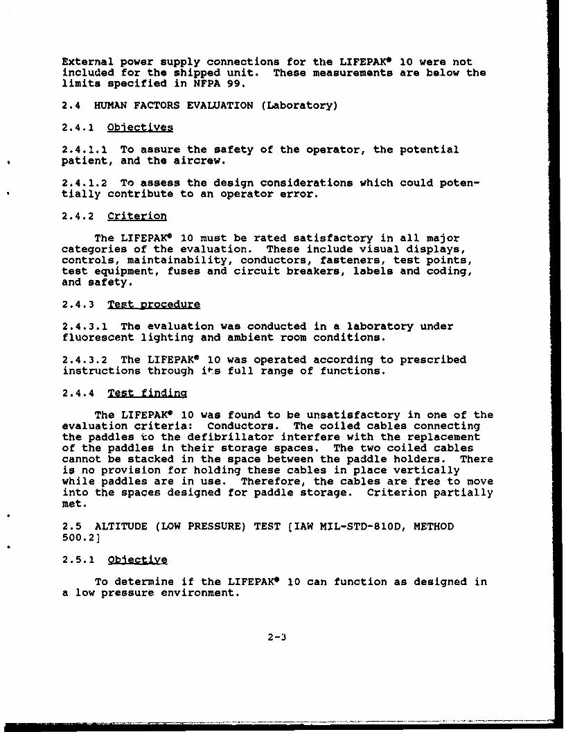
External power supply connections for the LIFEPAKe 10 were notincluded for the shipped unit. These measurements are below thelimits specified in NFPA 99.
2.4 HUMAN FACTORS EVALUATION (Laboratory)
2.4.1 ObJetives
2.4.1.1 To assure the safety of the operator, the potentialpatient, and the aircrew.
2.4.1.2 To assess the design considerations which could poten-tially contribute to an operator error.
2.4.2 Criterion
The LIFEPAKC 10 must be rated satisfactory in all majorcategories of the evaluation. These include visual displays,controls, maintainability, conductors, fasteners, test points,test equipment, fuses and circuit breakers, labels and coding,and safety.
2.4.3 Test procedure
2.4.3.1 The evaluation was conducted in a laboratory underfluorescent lighting and ambient room conditions.
2.4.3.2 The LIFEPAKe 10 was operated according to prescribedinstructions through its full range of functions.
2.4.4 Test finding
The LIFEPAKe 10 was found to be unsatisfactory in one of theevaluation criteria: Conductors. The coiled cables connectingthe paddles to the defibrillator interfere with the replacementof the paddles in their storage spaces. The two coiled cablescannot be stacked in the space between the paddle holders. Thereis no provision for holding these cables in place verticallywhile paddles are in use. Therefore, the cables are free to moveinto the spaces designed for paddle storage. Criterion partiallymet.
2.5 ALTITUDE (LOW PRESSURE) TEST (IAW MIL-STD-810D, METHOD
500.2]
2.5.1 Objective
To determine if the LIFEPAK0 10 can function as designed ina low pressure environment.
2-3

2.5.2 Criterion
The LIFEPAK* 10 will display consistent and accurate mea-surement of simulated ECG signals within ± 2 percent and deliverthe programmed defibrillator energy within 1 percent whileexposed to an altitude equivalency of 15,000 feet above sealevel.
2.5.3 Test procedure
2.5.3.1 A pretest performance check was conducted to ensureproper operation of the LIFEPAK 10.
2.5.3.2 The altitude test was performed in a Tenney Engineeringmodel 64S altitude chamber. This test is based on MIL-STD-810D,Method 500.2. The LIFEPAKX 10 was placed in operation near thecenter of the floor of the chamber. The LIFEPAKO 10 was turnedon by means of an armature through the chamber wall and made tomonitor a signal from an ECG simulator during the test. Thedefibrillator was not discharged during this test because thereare no provisions for operation from outside the chamber.Chamber pressure was decreased to 420 mm Hg (15,000 ft equivalentaltitude) over a 15-minute period, held constant for 60 minutes,then raised, at 1500 fpm, to ambient conditions (760 mm Hg) overa 10-minute period. There are no provisions for the control oftemperature or humidity inside this chamber.
2.5.3.3 A posttest performance check was conducted to ensureproper operation of the LIFEPAK* 10 after the exposure to lowpressure.
2.5.4 Test findinas
2.5.4.1 The pretest performance check met criterion 2.1.2.2.
2.5.4.2 No failures in the performance of the LIFEPAKO 10 werenoted before, during, or after the altitude test. Criterion met,
2.5.4.3 The posttest performance check met criterion 2.1.2.2.
2.6 VIBRATION TEST CIAW MIL-STD-810D, METHOD 514.3]
2.6.1 Qkiye
To determine the ability of the LIFEPAKO 10 to withstand thevibrational stresses expected in a rotary-wing environmentwithout degradation or malfunction.
2-4

2.6.2 riterion
While exposed to vibrational stresses, the LIFEPAK 10 willremain operational and be able to display consistent and accuratemeasurement of simulated ECG signals within ± 2 percent anddeliver the programmed defibrillator energy within 1 percent.
2.6.3 Test Drocedure
2.6.3.1 A pretest performance check was conducted to ensureproper operation of the LIFEPAKO 10.
2.6.3.2 The vibration test was performed using an Unholtz-Dickeymodel TAl15-40/CSTA vibration test system. It is a single-axissystem with an electromagnetic driver unit. The test consistedof sinusoidal vibrations superimposed on random vibrations over afrequency range of 500 Hz, as shown below. These vibrations arederived from measurements taken on the floor under the copilot'sseat in a UH-. helicopter traveling at 120 knots. The referencespectrum breakpoints are from MIL-STD-810D, Method 514.3; refer-ence spectrum levels are based on field measurements with aconservatism factor of 1.5. Independent tests were conducted inthe X, Y, and Z axes.
duration: 60 minutesbroadband intensity: 0.4506 G,.,random vibration: initial slope : 99.00 dB/Hz
5 Hz level: 0.00006210 GQrINz100 Hz level: 0.0006210 G,....,300 Hz level: 0,0006210 G,,,i.,500 Hz level: 0,00006210 G,Q.iHzfinal slope: -99.00 dB/oct
sinusoidal vibration: .5450 G,, at 11.25 Hz.1690 G9, at 22.50 Hz.1200 G,, at 33.75 Hz.0310 Gk• at 45.00 Hz.0530 G, at 56.25 Hz
X and Y axes
duration: 60 minutes eachbroadband intensity: 0.3099 G,o,random vibration: initial slope: 99.00 dB/oct
5 Hz level: 0.00002920 G,r/i.,,100 Hz level: 0.0002920 G .,...300 Hz level: 0.0002920 GsqINZ
500 Hz level: 0.00002920 Gs,,,,zfinal slope: -99.00 dB/oct
2-5
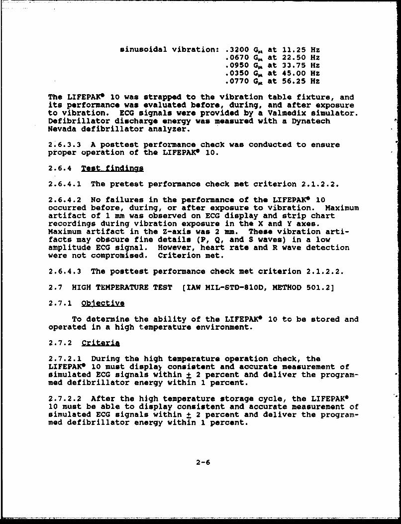
sinusoidal vibration: .3200 Go at 11.25 Hz.0670 Go at 22.50 Hz.0950 Gm at 33.75 Hz.0350 Gm at 45.00 Hz.0770 Gp at 56.25 Hz
The LIFEPAK* 10 was strapped to the vibration table fixture, andits performance was evaluated before, during, and after exposureto vibration. ECG signals were provided by a Valmedix simulator.Defibrillator discharge energy was measured with a DynatechNevada defibrillator analyzer.
2.6.3.3 A posttest performance check was conducted to ensureproper operation of the LIFEPAK* 10.
2.6.4 Test findings
2.6.4.1 The pretest performance check met criterion 2.1.2.2.
2.6.4.2 No failures in the performance of the LIFEPAIW 10occurred before, during, or after exposure to vibration. Maximumartifact of 1 mm was observed on ECG display and strip chartrecordings during vibration exposure in the X and Y axes.Maximum artifact in the Z-axis was 2 mm. These vibration arti-facts may obscure fine details (P, Q, and S waves) in a lowamplitude ECG signal. However, heart rate and R wave detectionwere not compromised. Criterion met.
2.6.4.3 The posttest performance check met criterion 2.1.2.2.
2.7 HIGH TEMPERATURE TEST (IAW MIL-STD-810D, METHOD 501.2]
2.7.1 oeive
To determine the ability of the LIFEPAKe 10 to be stored andoperated in a high temperature environment.
2.7.2 Crteria
2.7.2.1 During the high temperature operation check, theLIFEPAKe 10 must displal consistent and accurate measurement ofsimulated ECG signals within ± 2 percent and deliver the program-med defibrillator energy within 1 percent.
2.7.2.2 After the high temperature storage cycle, the LIFEPAKO10 must be able to display consistent and accurate measurement ofsimulated ECG signals within ± 2 percent and deliver the program-med defibrillator energy within 1 percent.
2-6

2.7.3 Test Drocedure
2.7.3.1 A pretest performance check was conducted to ensureproper operation of the LIFEPAKO 10.
2.7.3.2 The high temperature test was conducted in a TenneyEngineering model ZWUL-101O7D walk-in controlled environmentchamber. This test is based on MIL-STD-810D, Method 501.2. Forthe high temperature operation test, the LIFEPAK* 10 was placedin operation on a wire test stand near the center of theenvironmental chamber. The ECG leads were routed through aportal in the chamber wall to a Valmedix ECG simulator. Defib-rillator energy was measured with a Dynatech Nevada defibrillatoranalyzer. The chamber temperature was raised to 49"C and thehumidity was stabilized at a maximum of 20 percent RH within 15minutes. The environmental control system is capable of regulat-ing temperature within ±2"C and humidity within ±5 percent RH.Temperature and humidity were held constant for 2 hours. At 30-minute intervals, the chamber door was opened briefly to minimizethe change in chamber conditions during performance checks.After the operational test, the LIFEPAKO 10 was allowed to returnto ambient conditions over a 30-minute period.
2.7.3.3 A posttest performance check was conducted to ensureproper operation of the LIFEPAKO 10.
2.7.3.4 The LIFEPAKO 10 was stored (not operated) at tempera-tures of 63*C for 1 hour, 71"C for 4 hours, then again at 630Cfor 1 hour. The ECG cable was coiled and placed on top of thedefibrillator/monitor and the paddles were stored in theirholders. The chamber and LIFEPAKO 10 then were returned toambient conditions over a 30-minute period.
2.7.3.5 A poststorage performance check was conducted to ensureproper performance of the LIFEPAKO 10.
2.7.4 Test findinQs
2.7.4.1 The pretest performance check met criterion 2.1.2.2.
2.7.4.2 No operational failures occurred during the high temper-ature test. Criterion met.
2.7.4.3 The posttest performance check met criterion 2.1.2.2.
2.7.4.4 The LIFEPAKO 10 functioned properly after the hightemperature storage test. Criterion met.
2-7

2.8 LOW TEMPERATURE TEST (IAW MIL-STD-810D, METHOD 502.2]
2.8.1 QbJiect•i
To determine the ability of the LIFEPAKO 10 to be stored andoperated in a low temperature environment.
2.8.2 ri±&ris
2.8.2.1 During the low temperature operation check, the LIFEPAK*10 must display consistent ar.c accurate measurement of simulatedECG signals within ± 2 perceant and deliver the programmed defi-brillator energy within 1 percent.
2.8.2.2 After the low temperature storage cycle, the LIFEPAKG 10must be able to display consistent and accurate measurement ofsimulated ECG signals within ± 2 percent and deliver the pro-grammed defibrillator energy within 1 percent.
2.8.3 Test procedure
2.8.3.1 A pretest performance check was conducted to ensureproper operation of the LIFEPAKO 10.
2.8.3.2 The LIFEPAKO 10 was placed on the floor of the environ-mental chamber and the temperature was lowered to OC within 25minutes. The environmental control system is capable of regulat-ing temperature within 2"C. Humidity cannot be controlled in thechamber at freezing temperatures. The temperature was heldconstant for 2 hours. The chamber door was opened briefly, tominimize the change in chamber conditions, every 30 minutes and aperformance check was conducted. The chamber temperature thenwas raised to ambient temperature within a 30-minute period.
2.8.3.3 A posttest performance check was conducted to ensureproper operation of the LIFEPAK* 10.
2.8.3.4 The LIFEPAKO 10 was "stored" in a nonoperational modewith the power cord coiled and placed on top of the LIFEPAKO 10.The LIFEPAKO 10 was placed on the floor of the environmental testchamber and the temperature was lowered to -46 0C for 6 hours.The chamber then was raised to ambie.it temperature over a 30-minute period.
2.8.3.5 A poststorage perf:rmancc check was conducted to ensureproper operatio,. of tb1. LIFEPAKe 10.
2.8.4 Test findingE
2.8.4.1 The pretest performance check met criterion 2.1.2.2.
2-8

2.8.4.2 No operational failures occurred during the low tempera-
ture test. Criterion met.
2.8.4.3 The posttest performance check met criterion 2.1.2.2.
2.8.4.4 The LIFEPAKO 10 functioned properly after the lowtemperature storage test. Criterion met.
2.9 HUMIDITY TEST (IAW MIL-STD-810D, METHOD 507.2]
2.9.1 Objective
To determine the ability of the LIFEPAK8 10 to operatesatisfactorily for short periods of time during exposure tohighly humid conditions.
2.9.2 Criterion
While exposed to a high humidity environment, the LIFEPAK®10 must display consistent and accurate measurement of simulatedECG signals within + 2 percent and deliver the programmed defi-brillator energy within 1 percent.
2.9.3 Test procedure
2.9.3.1 A pretest performance check was conducted to ensure theproper operation of the LIFEPAK® 10.
2.9.3.2 The humidity test was conducted in a Tenney Engineeringmodel ZWUL-10107D walk-in controlled environment chamber. Thistest is based on MIL-STD-810D, Method 507.2. For the humiditytest, the LIFEPAK® 10 was placed in operation on a wire teststand near the center of the environmental chamber. The ECGleads were routed through a portal in the chamber wall to aValmedix ECG simulator. Defibrillator energy levels weremeasured with a Dynatech Nevada defibrillator analyzer. Thechamber temperature was raised to a temperature of 29.5"C and arelative humidity of 95 percent within 25 minutes. Temperatureand relative humidity were maintained for 4 hours. The environ-mental control system is capable of regulating temperature within±2"C and humidity within ±5 percent RH. At 45-minute intervalsthe defibrillator/monitor performance was checked. The chamberdoor was opened briefly to minimize the change in chamber condi-tions. The chamber and the LIFEPAK® 10 were returned to ambientconditions before the posttest performance validation check wasconducted.
2.9.3.3 A posttest performance check was conducted to ensure theproper operation of the LIFEPAK® 10.
2-9

2.9.4 Test findincs
2.9.4.1 The pretest performance check met criterion 2.1.2.2.
2.9.4.2 No failures were noted in the LIFEPAKO 10 performancechecks conducted during the exposure to the high humidity en-vironment. Criterion met.
2.9.4.3 The posttest performance check met criterion 2.1.2.2.
2.10 ELECTROMAGNETIC CHARACTERISTICS TEST [IAW MIL-STD-461A,Notice 4, MIL-STD-462, Notice 3, and MIL-STD-704C]
2.10.1 Objectives
2.10.1.1 To assess the maximum levels of radiated electromag-netic emissions produced by the LIFEPAKO 10 in the 14 kHz to 1.0GHz frequency range.
2.10.1.2 To assess the tolerances of radiated electromagneticsusceptibility of the LIFEPAK® 10 within the 10 kHz to 10 GHzbroadband electric field and the 14 kHz to 12.4 GHz narrowband.
2.10.2 Criteria
2.10.2.1 The LIFEPAKO 10 shall not produce emissions in excessof the limits set forth in MIL-STD-461A, Notice 4, paragraph6.13.
2.10.2.2 The LIFEPAK6 10 shall not malfunction when it is sub-jected to radiated emissions as specified in MIL-STD-461A, Notice4, paragraph 6.20.
2.10.3 Test-procedure
2.10.3.1 The radiated emissions test was performed according toMIL-STD-462, Notice 3, Method RE02. The LIFEPAKO 10 was posi-tioned on a wooden test stand 1 meter tall, 0.18 meters wide, and0.21 meters long, inside the EMI chamber. The unit was directlyin line with, and at a horizontal distance of 1 meter from thereceiving antennas. The antennas were mounted for both verticaland horizontal polarities and connected to the appropriate EMIreceivers. Electrometrics EMC-25 and EMC-50 receivers were usedfor this test. Their frequency ranges in testing are 14 kHz to 1GHZ and 1 to 12.4 GHz. Broadband and narrowband detectionmethods were used from 14 kHz to 1 GHz. Narrowband detectionmethods were used from 1 GHz to 12.4 GHZ. The monitor operatedcontinuously while displaying ECG signals provided by a ValmedixECG simulator. The defibrillator was charged to 100 joules anddischarged into a Dynatech Nevada defibrillator analyzer at 20-second intervals.
2-10

2.10.3.2 The radiated susceptibility test was performed accord-ing to MIL-STD-462, Notice 3, Method RS03. The LIFEPAK° 10 waspositioned on a wooden test stand I meter tall, 0.18 meters wide,and 0.21 meters long, inside the EMI chamber. The unit wasdirectly in line with, and at a horizontal distance of 1 meterfrom the transmitting antennas. The antennas were mounted forboth vertical and horizontal polarities and connected to radiofrequency (RF) transmitters. The defibrillator/monitor wasexposed to fields of 10 V/m from 200 MHz to 2 GHz, and 5 V/m from2 to 10 GHz. The LIFEPAK 10 was not tested in the frequencyrange 10 kHz to 200 MHz because the transmitter necessary forthese frequencies was out for repair. All RF carrier waves were50 percent amplitude modulated with a 1000 Hz tone. The ECGleads were routed through a wave guide tube through the chamberwall. ECG signals were provided by a Valmedix ECG simulator.The defibrillator was in standby mode during this test.
2.10.4 Test findings
2.10.4.1 During the radiated emissions test, narrowband andbroadband emissions which exceeded specification limits of MIL-STD-461, Notice 4, were detected in the frequency ranges below.
Frequuecy Amount of failure
191 kHz - 3.83 MHz 3.8 - 40.6 dB (NB)7.46 - 829.82 MHz 1.4 - 48.1 dB (NB)
191 kHz - 3.83 MHz 0.9 - 24.5 dB (BB)200 - 875 MHz 1.9 - 39.4 dB (BB)
criterion partially met.
2.10.4.2 The LIFEPAKe 10 was not found to be susceptible to anyfields generated during this test. No abnormalities were noticedin defibrillator/monitor operation as a result of exposure to thetest fields. Criterion met.
2.11 IN-FLIGHT HUMAN FACTORS EVALUATION
2.11.1 Obj..Qivj
To assess the physical and/or functional compatibility ofthe LIFEPAK 10 while in use onboard the aircraft.
2.11.2 Criterion
The flight surgeon shall be able to operate the LIFEPAKO 10without physical or functional restrictions aboard the aircraft.Major areas of concern include: Proper operation, visual dis-plays, controls, maintainability, conductors, fasteners, test
2-11

points, test equipment, fuses and circuit breakers, labels and
coding, and safety.
2.11.3 Test procedure
2.11.3.1 A human factors evaluation was performed in accordancewith MIL-STD-1472D, McCormick's Human Factors Evaluation Guide,and UL-544 to ensure the compatibility of the LIFEPAK° 10 and thein-flight environment. The flight surgeon conducted the testwearing a flight suit, flight gloves, and an SPH-4 flight helmet.An evaluation of the compatibility with the nuclear, biological,and chemical (NBC) protective equipment was not conducted.Due to restrictions of the AWR, testing was conducted duringdaylight hours only.
2.11.3.2 The LIFEPAK° 10 was placed on the top pan of the littercarousel which was configured for four patients. The littercarousel was flown in the "load" position (perpendicular to thelong axis of the helicopter). The LIFEPAK* 10 was tested in boththe defibrillation and monitoring modes in all flight scenariosrequired by the In-Flight Test Operations Procedures (ITOP)(refer to section 3.2).
2.11.4 Tegt fi ndogg
During the in-flight human factors evaluation, the LIFEPAKX10 was found to be satisfactory in all but two categories of theevaluation criteria. First, the deficiency noted in the labora-tory evaluation (paragraph 1.5.1.3) was exacerbated by thecramped quarters in the aircraft. Second, the flight surgeon wasunable to hear the audio alarms while wearing the required flightensemble. However, all audio alarms on the LIFEPAK* 10 arebacked up by visual alarms which are acceptable. Criterionpartially met.
2.12 IN-FLIGHT EMI/EMC CHARACTERISTICS
2.12.1 0
To assess the EMI/EMC characteristics of the LIFEPAKO 10with the host aircraft and its installed systems.
2.12.2 Crit.ria
2.12.2.1 The LIFEPAK* 10 shall not radiate EMI to disrupt orinterfere with other equipment or systems aboard the aircraft.
2.12.2.2 The aircraft shall not radiate EMI to disrupt orinterfere with the LIFEPAK* 10's operation.
2-12

2.12.3 Test procedure
A qualitative EMI/EMC assessment was performed with both theLIFEPAKO 10 and the aircraft operating as source and victim. TheLIFEPAKO 10 and applicable aircraft instruments and systems weremonitored for unusual operation, readings, surges, or poweranomalies for each checklist item (see pages 3-5 through 3-8).
2.12.4 Test findings
2.12.4.1 There were no adverse instances of EMI/EMC noted withthe LIFEPAKO 10 acting as either the source or victim. Criterionmet.
2.12.4.2 There were no adverse instances of EMI/EMC noted withthe aircraft acting as either the source or victim. Criterionmet.
2-13
SECTION 3. SUPPORTING DOCUMENTATION
3.1 DETAILED TEST INFORMATION
3.1.1 General information
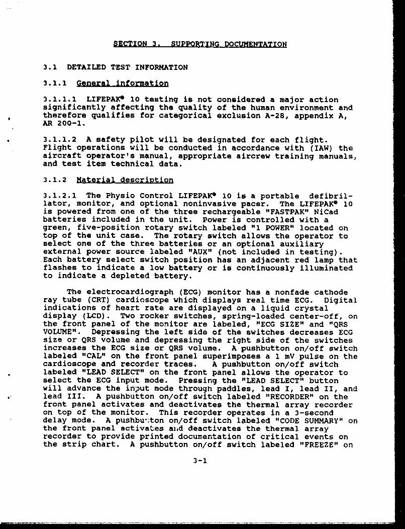
3.1.1.1 LIFEPAK* 10 testing is not considered a major actionsignificantly affecting the quality of the human environment andtherefore qualifies for categorical exclusion A-28, appendix A,AR 200-1.
3.1.1.2 A safety pilot will be designated for each flight.Flight operations will be conducted in accordance with (IAW) theaircraft operator's manual, appropriate aircrew training manuals,and test item technical data.
3.1.2 Material description
3.1.2.1 The Physio Control LIFEPAKC 10 is a portable defibril-lator, monitor, and optional noninvasive pacer. The LIFEPAK* 10is powered from one of the three rechargeable "FASTPAK" NiCadbatteries included in the unit. Power is controlled with agreen, five-position rotary switch labeled "1 POWER" located ontop of the unit case. The rotary switch allows the operator toselect one of the three batteries or an optional auxiliaryexternal power source labeled "AUX" (not included in testing).Each battery select switch position has an adjacent red lamp thatflashes to indicate a low battery or is continuously illuminatedto indicate a depleted battery.
The electrocardiograph (ECG) monitor has a nonfade cathoderay tube (CRT) cardioscope which displays real time ECG. Digitalindications of heart rate are displayed on a liquid crystaldisplay (LCD). Two rocker switches, spring-loaded center-off, onthe front panel of the monitor are labeled, "ECG SIZE" and "QRSVOLUME". Depressing the left side of the switches decreases ECGsize or QRS volume and depressing the right side of the switchesincreases the ECG size or QRS volume. A pushbutton on/off switchlabeled "CAL" on the front panel superimposes a 1 mV pulse on thecardioscope and recorder traces. A pushbutton on/off switchlabeled "LEAD SELECT" on the front panel allows the operator toselect the ECG input mode. Pressing the "LEAD SELECT" buttonwill advance the input mode through paddles, lead I, lead II, andlead III. A pushbutton on/off switch labeled "RECORDER" on thefront panel activates and deactivates the thermal array recorderon top of the monitor. This recorder operates in a 3-seconddelay mode. A pushbu':ton on/off switch labeled "CODE SUMMARY" onthe front panel activates and deactivates the thermal arrayrecorder to provide printed documentation of critical events onthe strip chart. A pushbutton on/off switch labeled "FREEZE" on
3-1

the front panel allows the operator to freeze the trace on thecardioscope as long as the pushbutton is held down. A pushbuttonswitch labeled "SYNC" on the front panel selects the synchronizeddischarge mode of defibrillation and "SYNC" is displayed on theLCD. Patient connection is vade, through a 6-pin Physio Controlpatient cable connector.
The defibrillator paddles a•re stored horizontally in slotson the front panel. Nine energy levels of 0, 5, 10, 20, 50, 100,200, 300, and 360 joules are ,-elected by a rotary switch labeled"2 ENERGY JOULES" located on iche sternum (left hand) paddle. Around, yellow pushbutton switch on the apex (right hand) paddlelabeled "CHARGE" allows the operator to initiate the defibril-lator charge cycle. A round, g-rey pushbutton switch on the apexpaddle labeled "RECORDER" activates the thermal recorder on themonitor. A digital readout: on -the LCD indicates available energywhen the defibrillator is energized. Pound, red pushbuttons onthe front of ea *,Add]e dischararxe the defibrillator when theyare pressed sir., Aeousiy.
3.1.2.2 Method of Operation: The LI1;'EPAK® 10 power switch ener-gizes the monitor and defibrillator. The ECG leads selector willbe set for "LEAD I!" upon startiup. The lead selector mode isdisplayed on the LCD screen below the heart rate readout. Theincoming ECG signal travel.s through the three-lead ECG cable tothe preamp circuitry in the monitor where it is amplified anddigitized. The signal then i•, filtered through the defibril-lator/ECG microcomputer which z -<es the digital ECG waveform tobe displayed on the CRT. Dyste;n integrity is monitored continu-ously by microprocessors which check read only memory (ROM),random access memory (RIAM), and software module check sums. Themonitor is controlled by a main control panel with pushbuttonsthat provide logic signals to an executive microprocessor. Thedefibrillator operates by reading the selected energy settingfrom the rotary dial on the sternum paddle when the charge buttonis pressed. A high voltage capacitor then is charged to theappropriate level. When the selected level has been reached, anaudible tone sounds and the yellow charging light emittingdisplay (LED) on the sternum paddle switches from flashing tocontinuous illumination. When the two round, red dischargebuttons -- located on the front of the paddles -- are pressedsimultaneously, contacts in thr.c transfer relay deliver highvoltage to the paddles. Depressing one discharge button alonewill not activate the transfer relay. Selecting another chargelevel with the rotary dial on t-.he sternum paddle after thecapacitor is charged will cause -the capacitor to dischargeinternally. Energy discharge through both paddles is controlledsolely by the paddle discharge buttons.
REPRODUCED FROMBEST AVAILABLE COPY
4;,

3.2 TEST DATA
3.2.1 Photographic Description
LIFEPAKlO0 with paddles stored.
LIFEPAK010 showing cable interference with paddle replacement.
3-3

3.2.2 Aircraft equipment list
Item No. Nomenclature
1 Receiver radio - R-1496A/ARN-89(automatic direction finder)
2 Displacement gyro - CN-1314/A3 Gyro directional - CN-998/ASN-434 Signal data converter - CV-3338/ASN-1285 Receiver - R-2139/ARN-123
(VOR/LOC/MB/GS)6 Command instrument system processor - 70600-01038-
1017 SAS amplifier - 70901-02908-104
(flight control stability augmentation system)8 Rate gyro - TRU-2A/A9 Amplifier, impedance - AM-4859A/ARN-89
10 Cargo hook - FE-7590-14511 Receiver, radar - RT-1193/ASN-128
(doppler navigation receiver)13 Barometric altimeter - AAU-31/A-i14 Barometric altimeter - AAU-32A15 Receiver/transmitter - RT-1300/ARC-186
(VHF-AM and/or FM radio)16 UHF-AM radio set - RT-1518/ARC-16417 Interphone control - C6533/ARC
(aircraft intercom control)18 Receiver/transmitter - RT-1115D/APN-209
(radar altimeter)19 Indicator altimeter - ID-1917C/APN-209
(radar altimeter)20 Control radio set - C-7392A/ARN-89
(automatic direction finder)21 Comparator signal data - CM-482/ARC-186
(comparator for ARC-186)22 Receiver/transmitter - RT-1296A/APX-100
(transponder with IFF)23 Computer display unit - CP-1252/ASN-128
(ioppler navigation system)24 Compass set controller - C-8021E/ASN7525 Magnetic compass - standby - MS-17983-4
3-4

3.2.3 In-flight test data card
DATA CARD FORMAT
GUIDELINE FOR DATA COLLECTION
IN-FLIGHT SUITABILITY TEST OF MEDICAL ITEMS
1. Installation/removal. Suitable CommentsYes No
a. Weight and balance X(DD Form 365-4, ClearanceForm F).
b. Space/area allocation.
(1) Operational Xrequirements.
(2) Storage requirements. X
c. Interface connections X(safe, positive, secure).
d. Installation/removal X(expedient/easily achieved).
e. Mounting/final config- Xuration (functional/stable).
2. operations and performance. Suitable CommentsYes No
a. Manufacturer's operating Xinstruction.
b. Medical item operation Xbefore aircraft runup.
c. System interface during Xaircraft engine runup andmedical item operation (EMIswitchology checklist).
(1) Aircraft voltage Xoutput.
3-5

(2) Flight control Suitable Commentsfunction (UH-60). Yes No
(3) Stabilator function X(UH-60).
(4) Radio communication
vs medical item operation.
(a) FM x
(b) UHF X
(C) VHF X
(5) Navigation equipmentvs medical item operation.
(a) Transponder X
(b) ADF X
(c) Vo0 x
(d) DOPPLER X
(6) Radar altimeter Xoperation vs medicalitem operation.
d. System interface during air-craft hover and medical itemoperation (EMI switchology check-list).
(1) Voltage output. n/a
(2) Radio communication vsmedical item operation.
(a) FM X
(b) UHF X
(c) VHF X
3-6

(3) Navigation equipment Suitable Commentsoperation vs medical item Yes Nooperation.
(a) Transponder X
(b) ADF X
(c) VOR X
(d) DOPPLER X
e. Flight mission profile vsmedical item operation (EMIswitchology checklist).
(1) Straight and level(1000 ft MSL for 20minutes).
(a) Compatibility of Xflight mode andmedical item operation.
(b) Radio communicationvs medical item opera-tion.
A. FM X
2. UHF X
C. VHF X
(2) NOE (20 minutes). Xcompatibility of flightmode and medical itemoperation.
(3) FM homing (10 minutes). X
(4) DOPPLER navigation vsmedical item operation.
(a) Initialize X
function.
(b) Fix function. X
(c) Update function. X
3-7
, ... .. ... .. .. .. .. . .... . . . . jj . .. . ..- .. . . - • - -l

Suitable CommentsYes No
(5) VOR navigation X7000 ft MSL for 20minutes) vs medicalitem operation.
(6) ILS approach vs Xmedical item operation.
f. Medical item operation Xafter engine shutdown(external power source).
g. Restrictions to the Xmedical item's use (i.e.,electrical connectors).
h. Deviations from the labor-atory test results.
(1) Electrical/ Noneelectronic.
(2) Mechanical Noneenvironment.
(3) Human factors None(user interface, controls,markings, lighting, egress).
(4) Safety. None
3. Deviations from the in-flight test protocol.
a. The VOR navigation portion of the in-flight test con-ducted at 2000 feet MSL due to air traffic control clearance.
3-8

3.2.4 EMI switcholoav checklist
EMI SWITCHOLOGY CHECKLIST UH-60 AIRCRAFT
IN-FLIGHT SUITABILITY OF MEDICAL ITEMS
ENG INSTRUMENTS/CDU No EMI EMI Affected ExplanationAffect Gnd Fit
Fuel quantity XFuel indicator test XXMSN oil temperature XXMSN oil pressure X#1 engine oil temperature X#2 engine oil temperature X#1 engine oil pressure X#2 engine oil pressure X#1 TGT X#2 TGT X#1 Ng speed X#2 Ng speed XCDU digits on/off XCDU instruments dim X
ENG INSTRUMENTS/PLT PDU No EMI EMI Affected ExplanationAffect Gnd Fit
#1 engine RPM X#2 engine RPM XRotor RPM X#1 torque X#2 torque X
ENG INSTRUMENTS/COPLT PDU No EMI EMI Affected ExplanationAffect Gnd Fit
#1 engine RPM X#2 engine RPM XRotor RPM X#1 torque X#2 torque X
3-9

ENG CONTROLS No EMI EMI Affected ExplanationAffect Gnd Fit
#1 overspeed X#2 overspeed XRPM switch X#1 engine anti-ice X#2 engine anti-ice X#1 inlet anti-ice X#2 inlet anti-ice X
RADIO EQUIPMENT No EMI EMI Affected ExplanationAffect Gnd Fit
ICS, C-6533 ARC XVHF-FM, ARC-186/115 XVHF-AM, ARC-186/115 XUHF-AM, ARC-164(V) XCrypto, KY-28 Not installedRadio retransmissions PLN Not installedTransponder, APX-lOO(V) XKIT-lA/TSEC IFF computer Not keyed with code
MISSION EQUIPMENT No EMI EMI Affected ExplanationAffect Gnd Flt
RWR, APR-39(V) Not installedIR CM, ALQ-144 Not installedChaff dispenser, M-130 Not installedCargo hook system X
HYDRAULIC CONTROL SYSTEM No EMI EMI Affected ExplanationAffect Gnd Fit
Backup hydraulic pump XServo off 1st stage/PLT XServo off 2nd stage/PLT XServo off 1st stage/COPLT XServo off 2nd stage/COPLT XHydraulic leak test XTail servo XBoost servos X
3-10
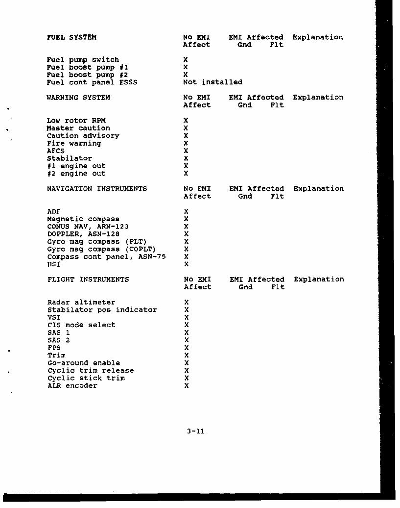
FUEL SYSTEM No EMI EMI Affected ExplanationAffect Gnd Flt
Fuel pump switch XFuel boost pump #1 XFuel boost pump #2 XFuel cont panel ESSS Not installed
WARNING SYSTEM No EMI EMI Affected ExplanationAffect Gnd Flt
Low rotor RPM XMaster caution XCaution advisory XFire warning XAFCS XStabilator X#1 engine out X#2 engine out X
NAVIGATION INSTRUMENTS No EMI EMI Affected ExplanationAffect Gnd Flt
ADF XMagnetic compass XCONUS NAV, ARN-123 XDOPPLER, ASN-128 XGyro mag compass (PLT) XGyro mag compass (COPLT) XCompass cont panel, ASN-75 XHSI X
FLIGHT INSTRUMENTS No EMI EMI Affected ExplanationAffect Gnd Flt
Radar altimeter XStabilator pos indicator XVSI XCIS mode select XSAS 1 XSAS 2 XFPS XTrim XGo-around enable XCyclic trim release XCyclic stick trim XALR encoder X
3-11
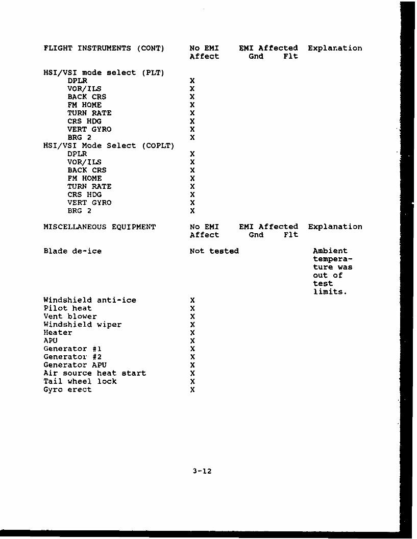
FLIGHT INSTRUMENTS (CONT) No EMI EMI Affected ExplanationAffect Gnd Flt
HSI/VSI mode select (PLT)DPLR XVOR/ILS XBACK CRS XFM HOME XTURN RATE XCRS HDG XVERT GYRO XBRG 2 X
HSI/VSI Mode Select (COPLT)DPLR XVOR/ILS XBACK CRS XFM HOME XTURN RATE XCRS HDG XVERT GYRO XBRG 2 X
MISCELLANEOUS EQUIPMENT No EMI EMI Affected ExplanationAffect Gnd Flt
Blade de-ice Not tested Ambienttempera-ture wasout oftestlimits.
Windshield anti-ice XPilot heat XVent blower XWindshield wiper XHeater XAPU XGenerator #1 XGenerator #2 XGenerator APU XAir source heat start XTail wheel lock XGyro erect X
3-12
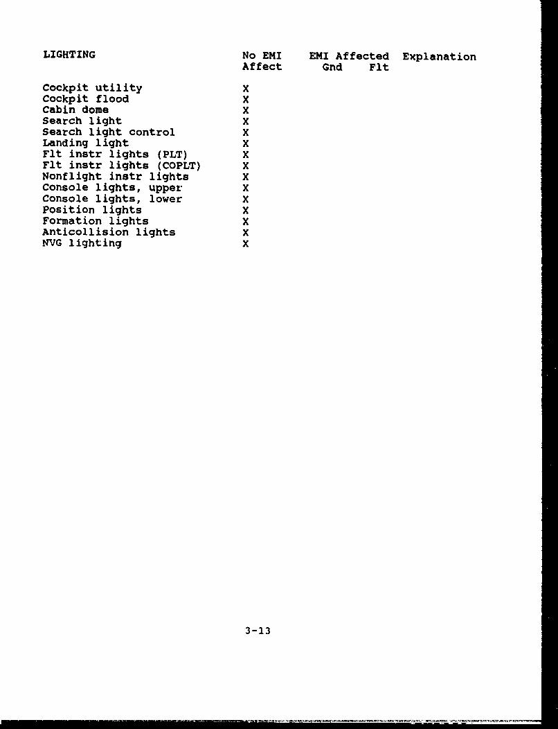
LIGHTING No EMI EMI Affected ExplanationAffect Gnd Flt
Cockpit utility XCockpit flood XCabin dome XSearch light XSearch light control XLanding light XFlt instr lights (PLT) XFlt instr lights (COPLT) XNonflight instr lights XConsole lights, upper XConsole lights, lower XPosition lights XFormation lights XAnticollision lights XNVG lighting X
3-13

3.2.5 Battery life evaluation
Battery Life EvaluationReport Form
Nomenclature: Defibrillator/MonitorManufacturer: Physio ControlModel number: LIFEPAKI 10Serial number: 00004322Military item number: None
Options installed: None
Manufacturer battery life specification:45 minutes in monitor mode
Specified battery recharge time:none; information not provided in manuals
Specified mode of operation under battery power:monitoring of ECG signal at 60 BPM
Overall performance: Pass
Measurements:
Dates of first test: 27 Dec 90Temperature: 22"CHumidity: 50% RHStart times: 0902End times: 1059Operating times: 1 hour 57 minutes
*** ** *** ** * ** * ** **
Total operating time: 1 hour 57 minutesPerformance: Pass
Dates of second test: 27 Dec 90Temperature: 23"CHumidity: 65% RHStart times: 0927End times: 1118Operating times: 1 hour 51 minutes
Total operating time: 1 hour 51 minutesPerformance: Pass
3-14
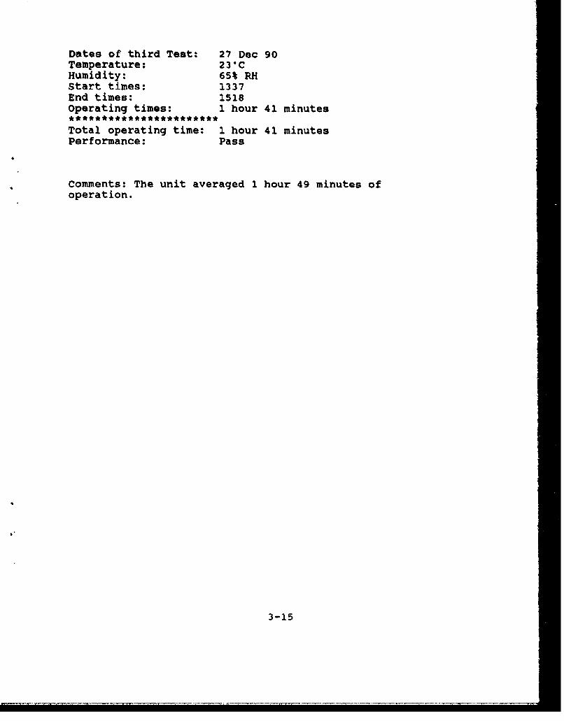
Dates of third Test: 27 Dec 90Temperature: 23"CHumidity: 65% RHStart times: 1337End times: 1518Operating times: 1 hour 41 minutes
Total operating time: 1 hour 41 minutesPerformance: Pass
Comments: The unit averaged 1 hour 49 minutes ofoperation.
3-15

3.2.6 Electrical safety test
Electrical Safety TestReport Form
Nomenclature: Defibrillator/monitorManufacturer: Physio ControlModel number: LIFEPAK* 10Serial number: 00004322Military item number: NoneLine cord identification: Northwire, Inc., 16/3, SJTOptions installed: None
Date of test: 21 Dec 90
Measurements:
Grounding conductor resistance (milliohms): 41.3
Leakage current - Case to ground (microamps):
unit off, grounded, normal polarity N/Aunit off, ungrounded, normal polarity N/Aunit off, ungrounded, reverse polarity N/A
unit on, grounded, normal polarity 5.0unit on, ungrounded, normal polarity 11.6unit on, ungrounded, reverse polarity 6.0
MAXIMUM LIMITS:ground resistance: 150 milliohmscurrent (grounded, type A unit): 10current (ungrounded, type A unit): 100current (grounded, type B unit): 50current (ungrounded, type B unit): 500
Comments on item set-up or checks:
The test was conducted on the battery charger. Thecharger does not have a power switch (always on whenplugged in). The defibrillator/monitor iscompletely battery powered with no external powerconductors.
Comments on test run (including interruptions):
Metal foil was used for leakage current tests on thecharger. It does not have an external groundedmetal surface. The ground conductor resistance wasmeasured at the AC cord connector.
3-16

Comments on other data:
Additional tests for defibrillators
Current to paddles ( ), EUT off: N/A(G, NP) (UG, NP) (UG, RP)
Current to paddles ( ), EUT on: N/A(G, NP) (UG, NP) (UG, RP)
Output energy (watt-seconds):
Control Energy Energysetting indicated delivered (Battery)
10 10 N/A 1020 20 N/A 2050 50 N/A 50
100 100 N/A 101200 200 N/A 196300 300 N/A 296360 360 N/A 354
Maximum time to full charge (seconds), AC: N/A DC: 10Maximum time for synchronized discharge (mS): 27
Comments on item set-up or checks:
Comments on test run (including interruptions):
Comments on other data:
3-17

3.2.7 Human factors evaluation
Human Factors EvaluationReport Form
Nomenclature: Defibrillator/MonitorManufacturer: Physio ControlModel number: LIFEPAK* 10Serial number: 00004322Military item number: None
Options installed: None
Date of test: 27 Dec 90
Item configuration during test:
Prepared for operation, sitting on a countertop.
Checklist for HFE
RESULTS
VISUAL DISPLAYS: Satisfactory
PASS: display type, format, contentPASS: location of displaysPASS: indicator lightsPASS: scalar displaysPASS: color codingPASS: legends and labelsPASS: cathode ray tubesPASS: countersPASS: flags, go/no go, center-null indicators
Comments:
CONTROLS: Satisfactory
PASS: locationPASS: characteristics of controlsPASS: labelingPASS: control - display relationships
3-18
Comments:
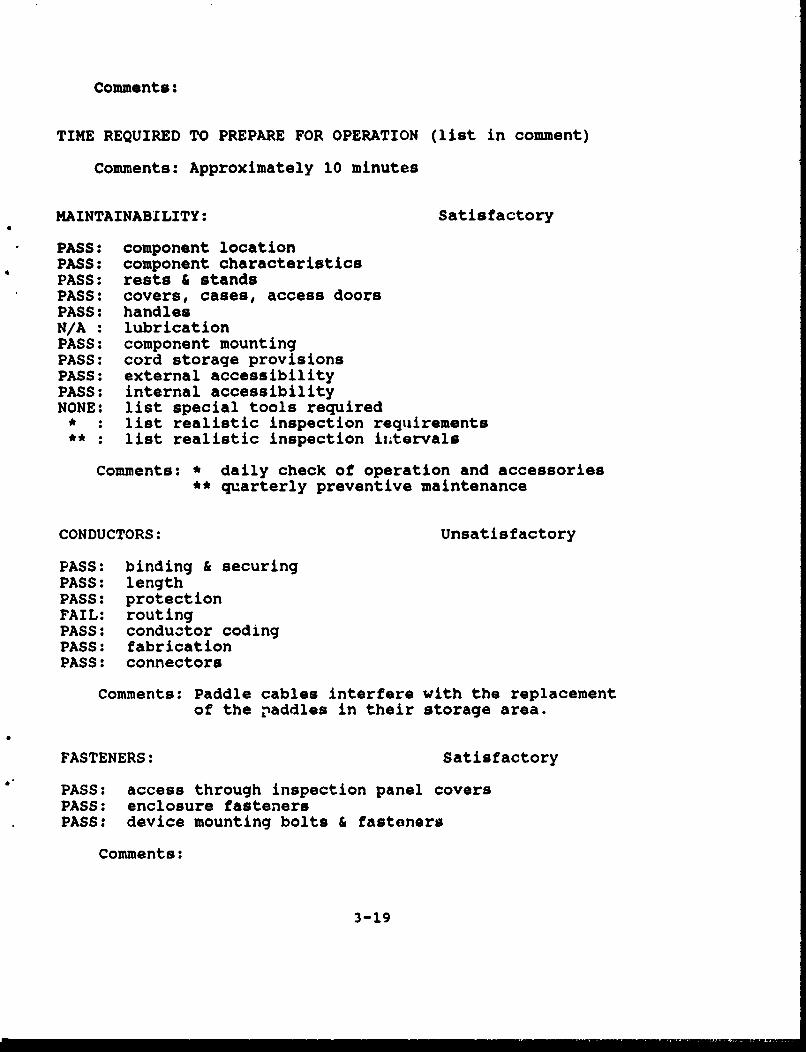
TIME REQUIRED TO PREPARE FOR OPERATION (list in comment)
Comments: Approximately 10 minutes
MAINTAINABILITY: Satisfactory
PASS: component locationPASS: component characteristicsPASS: rests & standsPASS: covers, cases, access doorsPASS: handlesN/A : lubricationPASS: component mountingPASS: cord storage provisionsPASS: external accessibilityPASS: internal accessibilityNONE: list special tools required
* : list realistic inspection requirements** : list realistic inspection izitervals
Comments: * daily check of operation and accessories** quarterly preventive maintenance
CONDUCTORS: Unsatisfactory
PASS: binding & securingPASS: lengthPASS: protectionFAIL: routingPASS: conductor codingPASS: fabricationPASS: connectors
Comments: Paddle cables interfere with the replacement
of the paddles in their storage area.
FASTENERS: Satisfactory
PASS: access through inspection panel coversPASS: enclosure fastenersPASS: device mounting bolts & fasteners
Comments:
3-19

TEST POINTS: N/A
N/A : generalN/A : location & mountingN/A : test point labeling & coding
Comments:
TEST EQUIPMENT: Satisfactory
PASS: generalPASS: equipment self-testPASS: indicators (list in comments)PASS: controlsPASS: positive indication of proper operation
Comments: All segments of the display screen areilluminated during the self-test. Failureis visible if the self-test finds an error.
FUSES & CIRCUIT BREAKERS: Satisfactory
PASS: external accessibilityPASS: easy replacement or reset by operator
Comments: A fuse is accessible on the battery chargeronly; fuses on the defibrillator/monitor areinternal.
LABELS & CODING: Satisfactory
PASS: placed above controls and displaysPASS: near or on the items they identifyPASS: not obscured by other equipment componentsPASS: describe the function of the items they identifyPASZ: readable from normal operating distancePASS: conspicuous placards adjacent to hazardous items
Comments:
3-20

SAFETY: Satisfactory
PASS: manualPASS: materialsPASS: fire & explosive protectionPASS: operator protection from mechanical hazardsPASS: patient protection from mechanical hazardsPASS: electrical safety (operator and patient)
Comments:
3-21

3.2.8 Altitude test
Altitude TestReport Form
Nomenclature: Defibrillator/MonitorManufacturer: Physio ControlModel number: LIFEPAK* 10Serial number: 00004322Military item number: None
Options installed: None
Date of test: 26 Dec 90
Item configuration during test:
Operating on the chamber floor with a simulated ECGsignal of 60 BPM.
Performance test criteria:
Consistent and accurate measurements of simulated ECGsignals and correct delivery of programmed defibrillatorenergy.
Ambient conditions outside chamber:
Temperature 75"FHumidity 50% RHBarometric pressure 1 atm
PRETEST DATA
Pretest performance check:Item functional (based on performance test criteria)
All OK Pass
Installation of item in test facility:list connections to power Nonelist connections to simulators Valmedix ECGlist connections to dummy loads Nonelist unconnected terminals Pace and Aux.
outlets
3-22
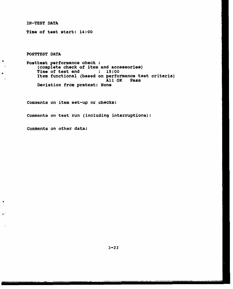
IN-TEST DATA
Time of test start: 14:00
POSTTEST DATA
Posttest performance check :(complete check of item and accessories)Time of test end : 15:00Item functional (based on performance test criteria)
All OK PassDeviation from pretest: None
Com•ents on item set-up or checks:
Comments on test run (including interruptions):
Comments on other data:
3-23

3.2.9 Vibration test
Vibration TestReport Form
Nomenclature: Defibrillator/MonitorManufacturer: Physio ControlModel number: LIFEPAKe 10Serial number: 00004322Military item number: None
Options installed: None
Date of test: 26 Dec 90
Item configuration during test:
Strapped down on vibration table fixture.
Performance test criteria:
Consistent and accurate measurement of simulated ECGsignals and correct delivery of programmeddefibrillator energy.
PRETEST DATA
Pretest pertormance check :Item functional (based on performance test criteria)
All OK Pass
Installation of item in test facility:list connections to power Nonelist connections to simulators Defibrillator
Analyzer, ValmedixECG
list connections to dummy loads Nonelist unconnected terminals Pace and Aux.
outlets
Ambient conditions
Temperature 70"FHumidity 50% RHBarometric pressure 1 atm
3-24

IN-TEST DATA
Data and performance checks during test:
Times and dates of test startX: 12/26/90, 0910 Y: 12/26/90, 1015 Z: 12/26/90, 1233
Time at first check:X: 0920 Y: 1020 Z: 1242Item functional (based on performance test criteria)
All OK PassDeviation from pretest: None
Time at second check:X: 1002 Y: 1107 Z: 1330Item functional (based on performance test criteria)
All OK PassDeviation from pretest: None
POSTTEST DATA
Time at test end:X: 1005 Y: 1115 Z: 1333
Posttest performance check:(complete check of item and accessories)Item functional (based on performance test criteria)
All OK PassItem intact: YesDeviation from pretest: None
Comments on item set-up or checks:
Comments on test run (including interruptions):
Comments on other data:
3-25

3.2.10 HiUh temperature test
High Temperature Test(equipment operating)
Report Form
Nomenclature: Defibrillator/MonitorManufacturer: Physio ControlModel number: LIFEPAK* 10Serial number: 00004322Military item number: None
Options installed: None
Date of test: 22 Dec 90
Item configuration during test:
Operating on wire test stand in the center of thechamber.
Performance test criteria:
Consistent and accurate measurement of simulated ECGsignals and correct delivery of programmeddefibrillator energy.
Ambient conditions outside chamber:
Temperature 23"CHumidity 54% RHBarometric pressure 1 atm
PRETEST DATA
Pretest performance checkItem functional (based on performance test criteria)
All OK Pass
Installation of item in test facility:list connections to power Nonelist connections to simulators Defibrillator
Analyzer, ValmedixECG
list connections to dummy loads Nonelist unconnected terminals Pace and Aux.
outlets
3-26

distance from north wall (meters) 0.57distance from south wall (meters) 0.57distance form east wall (meters) 1.22distance from west wall (meters) 1.38distance from ceiling (meters) 1.50distance from floor (meters) 0.50
Time of test start: 7:55
Performance checks during test:
First cneck:
Time: 8:25Temperature: 49"C ± 14CHumidity: 15% RH ± 1% RHBarometric pressure: 1 atmItem functional (based on performance test criteria)
All OK PassDeviation from pretest: None
Second check:
Time: 8:55Temperature: 49"C ± 1CHumidity: 15% RH ± 1% RHBarometric pressure: 1 atmItem functional (based on performance test criteria)
All OK PassDeviation from pretest: None
Third check:
Time: 9:25Temperature: 49"C ± V°CHumidity: 15% RH ± 1% RHBarometric pressure: 1 atmItem functional (based on performance test criteria)
All OK PassDeviation from pretest: None
3-27

POSTTEST DATA
Posttest performance check:(complete check of item and accessories)Time of test end: 9:55Item functional: (based on performance test criteria)
All OK PassDeviation from pretest: None
Comments on item set-up or checks:
Comments on test run (including interruptions):
Comments on other data:
3-28

3.2.11 High temperature storage test
High Temperature Test(equipment in storage)
Report Form
Nomenclature: Defibrillator/MonitorManufacturer: Physio ControlModel number: LIFEPAKO 10Sexial number: 00004322Military item number: None
Options installed: None
Date of test: 22 Dec 90
Item configuration during test:
Sitting on wire test stand in the center of thechamber. The unit is in storage, not operating.
Performance test criteria:
Consistent and accurate measurement of simulated ECGsignals and correct delivery of programmeddefibrillator energy.
Ambient conditions outside chamber:
Temperature 230CHumidity 54% RHBarometric pressure 1 atm
PRETEST DATA
Pretest performance check:Item functional (based on performance test criteria)
All OK Pass
Installation of item in test facility:list connections to power Nonelist connections to simulators Nonelist connections to dummy loads Nonelist unconnected terminals All (Pace and
Aux.)
3-29

distance from north wall (meters) 0.57distance from south wall (meters) 0.57distance form east wall (meters) 1.22distance from west wall (meters) 1.38distance from ceiling (meters) 1.50distance from floor (meters) 0150
Time of test start: 10:25Midtest time: 13:25Midtest temperature: 49"C ± 16CMidtest humidity: 15% RH ± 1% RH
POSTTEST DATA
Posttest performance check:(complete check of item and accessories)Time of test end: 16:25Item functional (based on performance test criteria)
All OK PassDeviation from pretest: None
Comments on item set-up or checks:
Comments on test run (including interruptions):
Comments on other data:
3-30

3.2.12 Low temperature test
Low Temperature Test(equipment operating)
Report Form
Nomenclature: Defibrillator/MonitorManufacturer: Physio ControlModel number: LIFEPAYK 10Serial number: 00004322Military item number: None
Options installed: None
Date of test: 23 Dec 90
Item configuration during test:
Operating on the wire test stand in the center ofthe chamber.
Performance test criteria:
Consistent and accurate measurement of simulated ECGsignals and correct delivery of programmeddefibrillator energy.
Ambient conditions outside chamber:
Temperature 240CHumidity 58% RHBarometric pressure 1 atm
PRETEST DATA
Pretest performance check:Item functional (based on performance test criteria)
All OK Pass
Installation of item in test facility:list connections to power Nonelist connections to simulators Defibrillator
Analyzer, ValmedixECG
list connections to dummy loads Nonelist unconnected terminals Pace and Aux.
outlets
3-31

distance from north wall (meters) 0.57distance from south wall (meters) 0.57distance form east wall (meters) 1.22distance *rom west wall (meters) 1.38distance •rom ceiling (meters) 1.50distance from floor (meters) 0.50
Time of test start: 7:55
Performance checks during test:
First check:
Time: 8:25Temperature: O.O0C ± 1° CHumidity: n/aBarometric pressure: 1 atmItem functional (based on performance test criteria)
All OK PassDeviation from pretest: None
Second check:
Time: 8:55Temperature: O.O0C ± i'CHumidity: n/aBarometric pressure: 1 atmItem functional (based on performance test criteria)
All OK PassDeviation from pretest: None
Third check:
Time: 9:25Temperature: 0.08C ± 10CHumidity: n/aBarometric pressure: 1 atmItem functional (based on performance test criteria)
All OK PassDeviation from pretest: None
3-32

POSTTEST DATA
Posttest performance check:(complete check of item and accessories)Time of test end: 9:55Item functional (based on performance test criteria)
All OK PassDeviation from pretest: None
Comments on item set-up or checks:
Comments on test run (including interruptions):
Comments on other data:
3-33

3.2.13 Low temperature storage test
Low Temperature Test(equipment in storage)
Report Form
Nomenclature: Defibrillator/MonitorManufacturer: Physio ControlModel number: LIFEPAKO 10Serial number: 00004322Military item number: None
Options installed: None
Date of test: 23 Dec 90
Item configuration during test:
Sitting on wire test stand in the center of thechamber. The unit is in storage, not operating.
Performance test criteria:
Consistent and accurate measurement of simulated ECGsignals and correct delivery of programmeddefibrillator energy.
Ambient conditions outside chamber:
Temperature 24"CHumidity 58% RHBarometric pressure 1 atm
PRETEST DATA
Pretest performance check:Item functional (based on performance test criteria)
All OK Pass
Installation of item in test facility:list connections to power: Nonelist connections to simulators: Nonelist connections to dummy loads Nonelist unconnected terminals All (Pace and
Aux.)
3-34

distance from north wall (meters) 0.57distance from south wall (meters) 0.57distance form east wall (meters) 1.22distance from west wall (meters) 1.38distance from ceiling (meters) 1.50distance from floor (meters) 0.50
Time of test start: 10:30Midtest time: 13:30Midtest temperature: -46"C ± IOC
POSTTEST DATA
Posttest performance check:(complete check of item and accessories)Time of test end: 15:10Item functional (based on performance test criteria)
All OK PassDeviation from pretest: None
Comments on item set-up or checks:
Comments on test run (including interruptions):
Comments on other data:
The EUT was allowed to return to ambient conditionsovernight.
F
3-35

3.2.14 Humidity test
Humidity TestReport Form
Nomenclature: Defibrillator/MonitorManufacturer: Physio ControlModel number: LIFEPAK 10Serial number: 00004322Military item number: None
Options installed: None
Date of test: 24 Dec 90
Item configuration during test:
Operating on the wire test stand in the center ofthe chamber.
Performance test criteria:
consistent and accurate measurement of simulated ECGsignals and correct delivery of programmeddefibrillator energy.
Ambient conditions outside chamber:
Temperature 24"CHumidity 40% RHBarometric pressure 1 atm
PRETEST DATA
Pretest performance check:Item functional (based on performance test criteria)
All OK Pass
Installation of item in test facility:list connections to power Nonelist connections to simulators Defibrillator
Analyzer, ValmedixECG
list connections to dummy loads Nonelist unconnected terminals Pace and Aux.
outlets
3-36

distance from north wall (meters) 0.57distance from south wall (meters) 0.57distance form east wall (meters) 1.22distance from west wall (meters) 1.38distance from ceiling (meters) 1.50distance from floor (meters) 0.50
IN-TEST DATA
Time of test start: 8:10
Performance checks during test:
First check:
Time: 8:55Temperature: 29.50C ± 1°CHumidity: 95% RH ± 1% RHBarometric pressure: 1 atmItem functional (based on performance test criteria)
All OK PassDeviation from pretest: None
Second check:
Time: 9:40Temperature: 29.5°C ± V'CHumidity: 95% RH ± 1% RHBarometric pressure: 1 atmItem functional (based on performance test criteria)
All OK PassDeviation from pretest: None
Third check:
Time: 10:25Temperature: 29.5°C ± I°CHumidity: 95% RH ± 3% RHBarometric pressure: 1 atmItem functional (based on performance test criteria)
All OK PassDeviation from pretest: None
3-37

Fourth check:
Time: 11:10Temperature: 29.59C ± VCHumidity: 95% RH ± 1% RHBarometric pressure: 1 atmItem functional (based on performance test criteria)
All OK PassDeviation from pretest: None
Fifth check:
Time: 11:55Temperature: 29.5"C ± VCHumidity: 95% RH ± 1% RHBarometric pressure: 1 atmItem functional (based on performance test criteria)
All OK PassDeviation from pretest: None
POSTTEST DATA
Posttest performance check:(complete check of item and accessories)Time of test end: 12:25Item functional (based on performance test criteria)
All OK PassDeviation from pretest: None
Comments on item set-up or checks:
Comments on test run (including interruptions):
Comments on other data:
""3
3-38

3.2.15 Eleotromagnetic characteristics Zest
Electromagnetic characteristics testingevaluation of performance
T & E Item Number: 27 Date: 21 Dec 90
Nomenclature: Defibrillator/Monitor Manufacturer: Physio Control
Model number: LIFEPAKe 10 Serial number: 00004322
Military item number: None
Conducted emissions '-ests
CE01 Testing configuration(s): n/aPerformance (pass/fail): n/aComments: The unit has no external power leads.
CE02 Testing configuration(s): n/aPerformance (pass/fail): n/aComments: The unit has no external power leads.
CE04 Testing configuration(s): n/aPerformance (pass/fail): n/aComments: The unit has no external power leads.
Conducted susceptibility tests
CS02 Testing configuration(s): n/aPerformance (pass/fail): n/aComments: The unit has no external power leads.
CS06 Testing configuration(s): n/aPerformance (pass/fail): n/aComments: The unit has no external power leads.
3-39

Radiated emissions tests
RE02 Testing configuration(s): Operating on wooden teststand in the EMC chamber.
Performance (pass/fail): FailComments:
Narrowband failure data dB of failure191 kHz - 3.83 MHz 3.8 - 40.67.46 MHz - 829.82 MHz 1.4 - 48.1
Broadband failure data db of failure191 kHz - 3.83 MHz 0.9 - 24.5200 MHz - 875 MHz 1.9 - 39.4
Radiated susceptibility tests
RS03 Testing configuration(s): Operating on the woodentest stand in the EMC chamber.
Performance (pass/fail): PassComments:The unit was not susceptible to the test fields
between 200 MHz and 10 GHz.
3-40

3.3 CRITERIA, SIGNIFICANT PROBLEMS, AND SUGGESTED IMPROVEMENTS
3.3.1 C
Item
SCriteria (Source) Remarks aubparagraD h
1 The physical inventory is con- N/A 2.1.2.1ducted solely for investigationand documentation.
2 The LIFEPAKO 10 will display a met 2.1.2.2consistent and accurate measure-ment of simulated ECG signalswithin ± 2 percent and deliverthe programmed defibrillator en-ergy within 1 percent.
3 Verify manufacturer's specified met 2.2.2full power battery life expec-tancy of 45 minutes during con-tinuous monitoring of a simu-lated ECG rate of 60 BPM.
4 The LIFEPAK® 10 shall meet the met 2.3.2limits established in NAFP 99for electrical safety of medicalequipment.
5 The LIFEPAK® 10 must be rated par- 2.4.2satisfactory in all major categ- tial-ories of the evaluation. These ly metinclude: Visual displays, con-trols, maintainability, con-ductors, fasteners, test points,test equipment, fuses and cir-cuit breakers, labels and cod-ing, and safety.
6 The LIFEPAK® 10 will display met 2.5.2consistent and accurate measure-ment of simulated ECG signalswithin ± 2 percent and deliverthe programmed defibrillator en-ergy within 1 percent while ex-posed to an altitude equivalencyof 15,000 feet above sea level.
3-41

7 While exposed to vibrational met 2.6.2stresses, the LIFEPAK* 10 willremain operational and be ableto display a consistent andaccurate measurement of simu-lated ECG signals within ± 2percent and deliver the pro-grammed defibrillator energywithin 1 percent.
8 During the high temperature met 2.7.2.1operation check, the LIFEPAKO 10must display consistent andaccurate measurement of simu-lated ECG signals within ± 2percent and deliver the pro-grammed defibrillator energywithin 1 percent.
9 After the high temperature stor- met 2.7.2.2age cycle, the LIFEPAKI 10 mustbe able to display consistentand accurate measurement of sim-ulated ECG signals within ± 2percent deliver the programmeddefibrillator energy within 1percent.
10 During the low temperature oper- met 2.8.2.1ation check, the LIFEPAKO 10must be able to display consis-tent and accurate measurement ofsimulated ECG signals within ± 2percent programmed defibrillatorenergy within 1 percent.
11 After the low temperature stor- met 2.8.2.2age cycle, the LIFEPAK® 10 mustbe able to display consistentand accurate measurement of sim-ulated ECG signals within ± 2percent and deliver the pro-grammed defibrillator energywithin 1 percent.
3-42

12 While exposed to a high humidity met 2.9.2environment, the LIFEPAKe 10must display consistent andaccurate measurement ofsimulated ECG signals within ± 2percent and deliver theprogrammed defibrillator energywithin 1 percent.
13 The LIFEPAKO 10 shall not pro- par- 2.10.2.1duce emissions in excess of the tiallylimits set forth in MIL-STD-461A metNotice 4, paragraph 6.13.
14 The LIFEPAKO 10 shall not mal- met 2.10.2.2function when it is subjected toradiated fields as specified inMIL-STD-461A, Notice 4, para-graph 6.20.
15 The flight surgeon shall be able par- 2.11.2.1to operate the LIFEPAK8 10 tiallywithout physical or functional metrestrictions aboard the air-craft.
16 The LIFEPAKO 10 shall not radi- met 2.12.2.2ate EMI to disrupt or interferewith the other equipment or sys-tems aboard the aircraft.
17 The aircraft shall not radiate met 2.12.2.3EMI to disrupt or interfere withthe LIFEPAKO 10.
3.3.2 Siqnificant problems which require corrective action
None
3.3.3 Suggested improvements Applicable
SuEcqestion Subparagraph
1. A method to channel or contain the 2.3.4 anddefibrillator cables between the paddles 2.10.4needs to be added. This would precludethe cables interference when replacingthe paddles in the LIFEPAKO 10.
3-43

3.4 REFERENCES
3.4.1 Department of Defense. 1971. £k.L __ a n .istics.requirements for eauiDment. Washington, D.C. MIL-STD-461A,Notice 4. February.
3.4.2 Department of Defense. 1971. EMI characteristics.meAsurement of. Washington, D.C. MIL-STD-462, Notice 3.February.
3.4.3 Department of Defense. 1983. Enviropmental test methodsand engineering guidelines. Washington, D.C. MIL-STD-810D.July.
3.A.4 Department of the Army. 1987. Maintenance managementDrocedures for medical eauipment. Washington, D.C. TB 38-750-2.April.
3.4.5 Department of Defense. 1985. Standard general reguire-ments for electronic eauipment. Washington, D.C. MIL-STD-454K.February.
3.4.6 Underwriters Laboratory's, Inc. 1978. Standard forsafety. medical and dental equipment. Chicago, Illinois.UL-544.
3.4.7 Department of Defense. 1989. Human engineering d•qjncriteria for military systems equipment. and facilities.Washington, D.C. MIL-STD-1472D. March.
3.4.8 Association for the Advancement of Medical Instruments.Human factors engineering guidelines and preferred practices forthe design of medical devices. Arlington, Virginia. AAMI-HE-1988. February.
3.4.9 Department of the Army. 1978. Operator's manual. UH-60and EH-60 helicopter. with changes 1-5. Washington, D.C.TM 55-1520-237-10. January.
3.4.10 Department of the Army. 1987. Maintenance managementprocedures for medical eqvipment. Washington, D.C. TB 38-750-2.April.
3.4.11 National Fire Protection Association. 1987. Standarfor health care tacilities. Quincy, Massachusetts. February.
3-44

3.4.12 Physio Control. 1989. Ogerating instructions. LIFEPA1010 defibrillator/monitor. Redmond, Washington.
3.4.13 Mitchell, G. W., and Adams, J. E. 1988. Technical testand evaluation .,fer 4JcLlftraj&MWqunn/ . Fort Rucker, AL: U. S.Army Aeromedical Research Laboratory. USAARL Letter ReportLR-88-16-1-2.
3-45

3.5 ABBREVIATIONS
AVSCOM Army Aviation Systems CommandAEST aeromedical equipment suitability testAWR airworthiness release
BB broadbandBPM beats per minute
CAAF Cairns Army AirfieldCRT cathode ray tube
DC direct current
ECG electrocardiographEMC electromagnetic compatibilityEMI electromagnetic interference
fpm feet per minute
GFE government furnished equipmentGpk gravity, peakG(rms) gravity (root mean square)
Hz hertz
IAW in accordance withITOP in-flight test operating procedureIGE in-ground effect
KHz kilohertzKIAS knots indicated airspeed
LCD liquid crystal displayLED light emitting diodeLIFEPAK* 10 Physio Control defibrillator/ironitor,
model LIFEPAK* 10
MEDEVAC medical evacuationMHz mega hertzMIL-STD military standardml millilitermm millimetermmHg millimeters of MercuryMSL mean sea level
NAFP National Association of Fire PreventionNB nairowbandNBC nuclear, biological ana chemicalNiCad nickel cadmiumNVG night vision goggle
3-46

RAM random access memoryRF radio frequencyRH relative humidityROM read only memory
TB technical bulletinTFT technical feasibility testingT & E test and evaluation
UES Universal Energy Systems, Inc.USAARL U. S. Army Aeromedical Research Laboratory
V/M volts per meter
3-47