tessera led video processing system - brompton...
TRANSCRIPT

Tessera LED Video Processing System

A state of the art video processing system for LED panels delivering industry leading performance
Tessera LED Video Processing System
The Tessera family currently has two processors, with other models available in the near future.
The processors feature powerful front end processing such as broadcast quality scaling and motion adaptive de-interlacing, so there is no need to use an external scaler/scan converter. Each input can be fully configured with contrast, brightness, gamma, hue, saturation, RGB gain, and can be scaled up or down to fit the LED panel configuration as necessary. The inputs can be switched or faded cleanly. By bypassing the scaler and mixer the processor can be used in low latency mode.
Video data is sent to the panels via Gigabit Ethernet over conventional Cat 5e cable, allowing the Tessera system to use conventional Gigabit Ethernet equipment. Each Ethernet output can support up to 500,000 pixels, and by using bilinear interpolation different pixel pitch panels can be used with in the same configuration as well as panel rotation. Each panel is completely synchronised with the other panels in the configuration, and can be synchronised to a source or an external genlock.
Each Tessera compatible LED panel contains a Tessera Panel Controller Board, with input and pass-through connections allowing the video data to daisy chained. Each Panel Controller Board is intelligent and can send back panel status and diagnostic information via the Ethernet connection to the processor, as well as being able receive firmware updates from the processor. As the Panel Controller Boards are fitted with an accelerometer, the panels can also send back real time rotation information to the processor.
The system is configured using the intuitive and powerful Tessera software, either from a remote Mac or Windows PC, or locally, by plugging in a mouse, keyboard and monitor into the processor. Real time previews are available to assist with system setup, and to confirm source status.
Tessera processors can be controlled with DMX512 or eDMX protocols such as Pathport, Streaming ACN or Artnet.
The full range of features available within the Tessera system ensures robust reliable operation with ease of use, even for large, complex layouts or situations demanding superior video performance.
The Brompton Technology Tessera LED Video Processing system combines industry leading performance and functionality with powerful real time control. The system’s ease of use and quick set up makes even complex layouts of LED panels simple to configure, and together with the system’s powerful feature set allows unequalled creative possibilities for shows and events.The Brompton Technology Tessera LED Video Processing system
comprises of 4 distinct components: Tessera LED Video Processor, the Tessera Panel Controller Boards which are fitted to host LED panels, the Tessera Protocol, which allows the processor to communicate with host LED panels fitted with Tessera Panel Controller Boards, and the Tessera Management Software, which can run remotely on a Windows PC or Mac, or locally on the processor itself, by connecting a keyboard, mouse and a monitor.
DVI
Y Pb Pr
3G-SDI
Video
Inputs
Remote Control LocalControl
Real-timeControl
Ethernet-BasedPanel Data
Ethernet Switch
LED Panels
DMX-512
DVI-DVGA
Tessera LED Video Processor

Video InputsThe Tessera M2 Video Processor supports video input in a range of common formats. The DVI-I input is capable of receiving digital (DVI-D) or analog (VGA/RGBHV) signals up to full HD 1080p60 resolution at frame rates from 24Hz to 60Hz. It may also be used to receive standard definition or high definition component video (YPbPr) via a passive DVI to BNC breakout cable.
For applications requiring broadcast-standard digital video input, two SDI inputs are provided, each supporting SD-SDI, HD-SDI and 3G-SDI (both Level A and Level B compatible). These inputs may be combined together to offer a dual-link HD-SDI input if required. All common broadcast resolutions are supported, including 720p50/60, 1080i50/60 and 1080p50/60 and fractional frame rates such as 59.94.
The frame timing may be locked to any of the input signals, or a reference sync input is available to genlock the entire system to an external bi-level or tri-level sync.
All video inputs feature brightness, contrast, saturation and gamma controls, and all video and sync inputs have pass through connectors, allowing for stacking of processors or connection of other equipment.
For times when external video sources are not available, an internal test pattern generator may be used to display a range of static and
animated test patterns specifically designed for LED wall testing.
Front End Video ProcessingTwo video input paths are available to enable processing to be performed on the current input source and the next input source. Any input port may be routed to either input path to provide fully flexible source selection.
Interlaced input signals are fed through a high quality, motion-adaptive deinterlacer to convert them to progressive scan signals as required for inherently progressive displays such as LED walls.A high quality polyphase scaler provides the option to scale incoming video to larger or smaller sizes as required to ensure the desired image is displayed at the correct size on the LED wall. The scaler can also be disabled to ensure 1:1 pixel mapping if required.Both input paths are synchronised and fed through a mixer to provide cut and dissolve transitions from the current source to the next source.
Video is processed internally at up to 12 bit, 4:4:4, ensuring the image quality is maintained at all times.
In situations demanding the lowest possible latency, the video input paths can be bypassed and progressive video is fed directly from an input into the rest of the system. In this mode, no de-interlacing, scaling or mixing is available, but latency is reduced by one frame.This combination of multiple input ports and powerful internal video processing means that the requirement for multiple external format converters, scalers and mixers is reduced or eliminated altogether, resulting in lower overall system cost and complexity.
Gigabit Ethernet for remote managment
DVI-I Video In and through
DMX-512 Input
USB and DisplayPortfor local user interface
Reference In and through
Dual 3G-SDI Video In and through
Tessera Protocol Outputs to LED panels
Autoranging mains input
DisplayPort In and through
In development
3G-SDI B
DVI-D
VGA
YPbPr
3G-SDI A
Input Switch
Deinterlacer
Deinterlacer
Scaler
Scaler
MixerArea
SelectorPanel
Rotator
Tessera Protocol
Tessera Protocol
Front End Processing Panel Extraction Output
Panel ExtractionThe video feed resulting from the video front end is next processed to extract the desired areas of the image for each LED panel connected to the controller. Each panel may be freely located within the full frame area with sub-pixel accuracy. Panels may also be individually rotated to any angle for creative integration into set designs.
Multiple panel types are supported simultaneously, regardless of size, shape, resolution or pixel pitch. Differing pixel pitches are handled using bilinear interpolation to maintain image quality.Panel extraction can also operate in a 1:1 pixel mapping mode to ensure perfect 1:1 mapping of input pixels to LEDs on panels.
OutputsFour Tessera Protocol outputs are available on Neutrik etherCON locking connectors. These are backwards compatible with standard RJ45 plugs to support off-the-shelf Cat 5e cables if preferred.Each output supports 500,000 pixels at 24 bits per pixel and 60 Hz. LED panels may be connected to either output with no restrictions on the panel type or the panel’s location within the screen. All outputs are synchronised together, matching the timing of the video or sync input selected as the system timing reference.
Colour ManagementEnd-to-end colour management is supported to ensure colours are faithfully reproduced, even when combining sources operating in
different colour spaces, such as standard definition video in Rec. 601 format and high definition video in Rec. 709 format. Colours may also be manually adjusted for situations requiring further control.
ControlFull control of all features is available without requiring an external computer. A DisplayPort or DVI monitor (via a low cost DisplayPort to DVI adaptor) may be connected, along with a USB keyboard and mouse to provide access to the local user interface, detailed overleaf.
Remote configuration and control is also supported from a PC or Mac connected to the remote management port via Ethernet, offering the same user interface as is available locally. Neither local nor remote user interfaces are required for operation - once configured the system can be used ‘headless’ for fixed installations, with status LEDs on the front panel confirming system operation.
For seamless integration with a lighting control system, channels from a DMX512 input signal or DMX-over-Ethernet such as Artnet or streaming ACN can be configured to control a wide range of parameters including input port selection, panel positioning, RGB gains and screen luminance. These may be updated at the full refresh rate offered by DMX, enabling real-time dynamic control.
Tessera Management Software
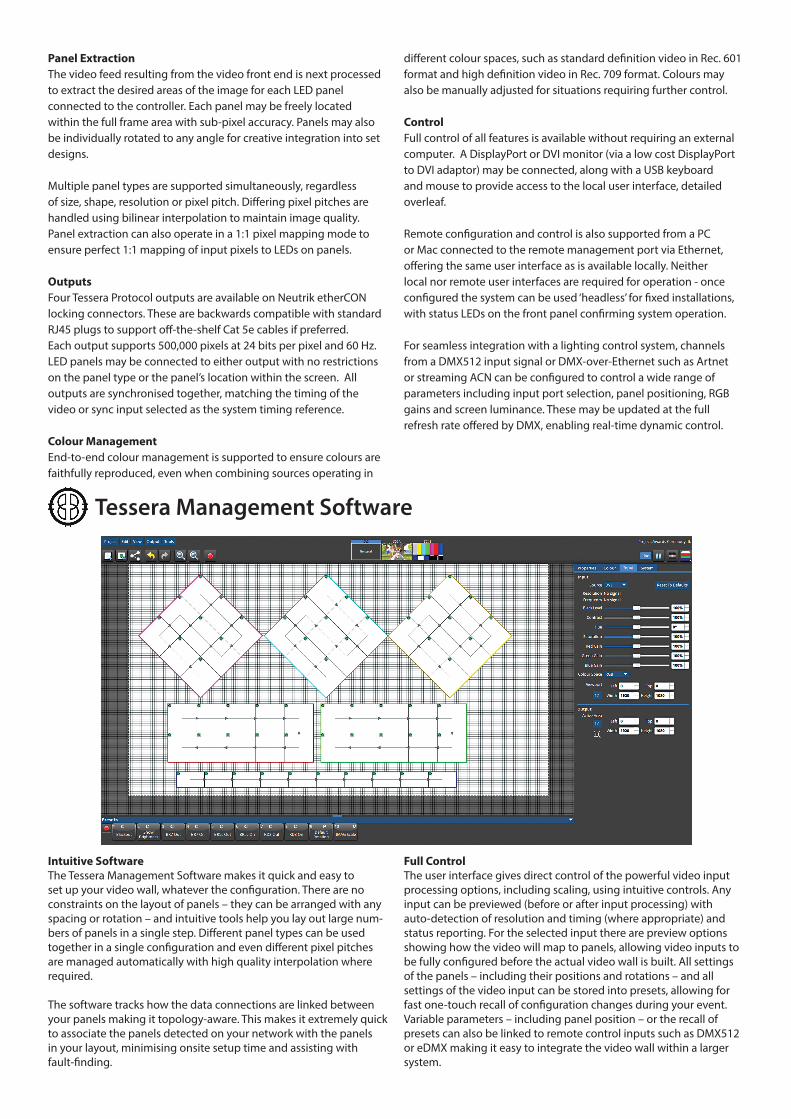
Intuitive SoftwareThe Tessera Management Software makes it quick and easy to set up your video wall, whatever the configuration. There are no constraints on the layout of panels – they can be arranged with any spacing or rotation – and intuitive tools help you lay out large num-bers of panels in a single step. Different panel types can be used together in a single configuration and even different pixel pitches are managed automatically with high quality interpolation where required.
The software tracks how the data connections are linked between your panels making it topology-aware. This makes it extremely quick to associate the panels detected on your network with the panels in your layout, minimising onsite setup time and assisting with fault-finding.
Full ControlThe user interface gives direct control of the powerful video input processing options, including scaling, using intuitive controls. Any input can be previewed (before or after input processing) with auto-detection of resolution and timing (where appropriate) and status reporting. For the selected input there are preview options showing how the video will map to panels, allowing video inputs to be fully configured before the actual video wall is built. All settings of the panels – including their positions and rotations – and all settings of the video input can be stored into presets, allowing for fast one-touch recall of configuration changes during your event. Variable parameters – including panel position – or the recall of presets can also be linked to remote control inputs such as DMX512 or eDMX making it easy to integrate the video wall within a larger system.
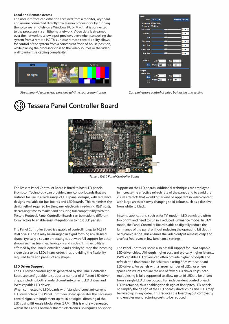
Local and Remote AccessThe user interface can either be accessed from a monitor, keyboard and mouse connected directly to a Tessera processor or by running the software remotely on a Windows PC or Mac that is connected to the processor via an Ethernet network. Video data is streamed over the network to allow input previews even when controlling the system from a remote PC. This unique remote control ability allows for control of the system from a convenient front-of-house position, while placing the processor close to the video sources or the video wall to minimise cabling complexity.
Comprehensive control of video balancing and scalingStreaming video previews provide real-time source monitoring
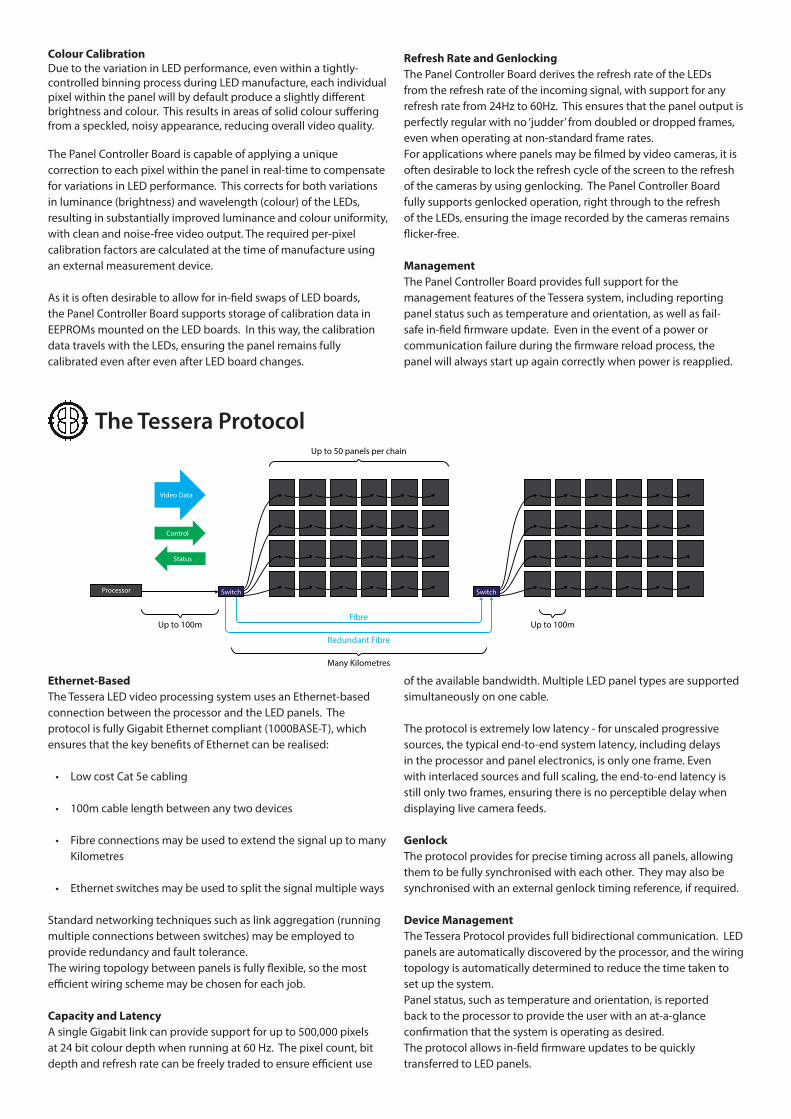
The Tessera Panel Controller Board is fitted to host LED panels. Brompton Technology can provide panel control boards that are suitable for use in a wide range of LED panel designs, with reference designs available for bus boards and LED boards. This minimises the design effort required for the panel electronics, reducing R&D costs, decreasing time to market and ensuring full compatibility with the Tessera Protocol. Panel Controller Boards can be made to different form factors to enable easy integration in to host LED panels
The Panel Controller Board is capable of controlling up to 16,384 RGB pixels. These may be arranged in a grid forming any desired shape, typically a square or rectangle, but with full support for other shapes such as triangles, hexagons and circles. This flexibility is afforded by the Panel Controller Board’s ability to map the incoming video data to the LEDs in any order, thus providing the flexibility required to design panels of any shape.
LED Driver SupportThe LED driver control signals generated by the Panel Controller Board are configurable to support a number of different LED driver chips, including both standard constant-current LED drivers and PWM capable LED drivers.When connected to LED boards with ‘standard’ constant-current LED driver chips, the Panel Controller Board generates the necessary control signals to implement up to 16 bit digital dimming of the LEDs using Bit Angle Modulation (BAM). This is entirely generated within the Panel Controller Board’s electronics, so requires no special
support on the LED boards. Additional techniques are employed to increase the effective refresh rate of the panel, and to avoid the visual artefacts that would otherwise be apparent in video content with large areas of slowly changing solid colour, such as a dissolve from white to black.
In some applications, such as for TV, modern LED panels are often too bright and need to run in a reduced luminance mode. In BAM mode, the Panel Controller Board is able to digitally reduce the luminance of the panel without reducing the operating bit depth or dynamic range. This ensures the video output remains crisp and artefact free, even at low luminance settings.
The Panel Controller Board also has full support for PWM capable LED driver chips. Although higher cost and typically higher latency, PWM capable LED drivers can often provide higher bit depth and refresh rate than would be achievable using BAM with standard LED drivers. For panels with a larger number of LEDs, or where space constraints require the use of fewer LED driver chips, scan multiplexing is fully supported to allow up to 16 LEDs to be driven from a single LED driver output. Full independent control of each LED is retained, thus enabling the design of finer pitch LED panels.To simplify the design of the LED boards, driver chips and LEDs may be wired up in any order. This reduces the board layout complexity and enables manufacturing costs to be reduced.
Tessera Panel Controller Board
Tessera RA16 Panel Controller Board
Colour CalibrationDue to the variation in LED performance, even within a tightly-controlled binning process during LED manufacture, each individual pixel within the panel will by default produce a slightly different brightness and colour. This results in areas of solid colour suffering from a speckled, noisy appearance, reducing overall video quality.
The Panel Controller Board is capable of applying a unique correction to each pixel within the panel in real-time to compensate for variations in LED performance. This corrects for both variations in luminance (brightness) and wavelength (colour) of the LEDs, resulting in substantially improved luminance and colour uniformity, with clean and noise-free video output. The required per-pixel calibration factors are calculated at the time of manufacture using an external measurement device.
As it is often desirable to allow for in-field swaps of LED boards, the Panel Controller Board supports storage of calibration data in EEPROMs mounted on the LED boards. In this way, the calibration data travels with the LEDs, ensuring the panel remains fully calibrated even after even after LED board changes.
Refresh Rate and GenlockingThe Panel Controller Board derives the refresh rate of the LEDs from the refresh rate of the incoming signal, with support for any refresh rate from 24Hz to 60Hz. This ensures that the panel output is perfectly regular with no ‘judder’ from doubled or dropped frames, even when operating at non-standard frame rates.For applications where panels may be filmed by video cameras, it is often desirable to lock the refresh cycle of the screen to the refresh of the cameras by using genlocking. The Panel Controller Board fully supports genlocked operation, right through to the refresh of the LEDs, ensuring the image recorded by the cameras remains flicker-free.
ManagementThe Panel Controller Board provides full support for the management features of the Tessera system, including reporting panel status such as temperature and orientation, as well as fail-safe in-field firmware update. Even in the event of a power or communication failure during the firmware reload process, the panel will always start up again correctly when power is reapplied.
The Tessera Protocol
Ethernet-BasedThe Tessera LED video processing system uses an Ethernet-based connection between the processor and the LED panels. The protocol is fully Gigabit Ethernet compliant (1000BASE-T), which ensures that the key benefits of Ethernet can be realised:
• Low cost Cat 5e cabling
• 100m cable length between any two devices
• Fibre connections may be used to extend the signal up to many Kilometres
• Ethernet switches may be used to split the signal multiple ways
Standard networking techniques such as link aggregation (running multiple connections between switches) may be employed to provide redundancy and fault tolerance.The wiring topology between panels is fully flexible, so the most efficient wiring scheme may be chosen for each job.
Capacity and LatencyA single Gigabit link can provide support for up to 500,000 pixels at 24 bit colour depth when running at 60 Hz. The pixel count, bit depth and refresh rate can be freely traded to ensure efficient use
of the available bandwidth. Multiple LED panel types are supported simultaneously on one cable.
The protocol is extremely low latency - for unscaled progressive sources, the typical end-to-end system latency, including delays in the processor and panel electronics, is only one frame. Even with interlaced sources and full scaling, the end-to-end latency is still only two frames, ensuring there is no perceptible delay when displaying live camera feeds.
GenlockThe protocol provides for precise timing across all panels, allowing them to be fully synchronised with each other. They may also be synchronised with an external genlock timing reference, if required.
Device ManagementThe Tessera Protocol provides full bidirectional communication. LED panels are automatically discovered by the processor, and the wiring topology is automatically determined to reduce the time taken to set up the system.Panel status, such as temperature and orientation, is reported back to the processor to provide the user with an at-a-glance confirmation that the system is operating as desired.The protocol allows in-field firmware updates to be quickly transferred to LED panels.
Video Data
Control
Status
Processor
Up to 100m Up to 100m
Up to 50 panels per chain
Switch
Many Kilometres
Fibre
Redundant Fibre
Switch

Tessera M1 and M2 Processors• Solid State electronics in a custom designed, rugged, tour-
friendly 2U rackmount enclosure
• Reliable embedded electronics - not a PC
• DVI-I support for resolutions up to 1080p60
• Support for analog component video (YPbPr) at standard defintion and high definition
• SDI inputs supporting HD SDI, Dual Link and 3G SDI
• Pass through connections on all inputs for easy stacking of equipment
• Auto detection of incoming video resolutions
• EDID management of VGA and DVI sources
• Timing can be locked to any input signal or a dedicated sync input for bi-level and tri-level genlock
• Brightness, contrast, RGB gain and gamma controls on all video inputs
• Test Pattern generator specifically designed for LED panel set up
• Broadcast quality scaling and motion-adaptive deinterlacing
• Built in mixer allows transitions and fades between sources
• Can bypass scaler for low latency mode
• Individual panels can be rotated with sub-pixel accuracy or rotated to any angle
• Different pixel pitches can be used together with bilinear interpolation to maintain quality
• 1:1 pixel mapping mode
• End-to-end colour management even when combining sources with different colour spaces
• Gigabit Ethernet compliant protocol allows use of Cat 5e cable and conventional Gigabit switches
• Each data output supports 500,000 pixels at 24 bits per pixel and 60Hz
• Output video data processed at up to 36 bits per pixel
• Synchronisation timing is maintained across the network connections to the panels
• DMX512 or eDMX control
Tessera Panel Controller • Support for panels of any shape
• Support for a variety of LED driver chips including constant current and PWM drivers
• Bit Angle Modulation at up to 16 bit per colour and high effective refresh rates
• Intelligent techniques for maintaining bit depth during low brightness operation, such as indoor applications
• Scan multiplexing up to 16:1
• Fully flexible driver chip and LED routing topology
• Per pixel calibration corrects LED for both luminance and colour variation
• All panels are synchronised together, right through to LED refresh
• Automatic discovery and network topology detection over Gigabit Ethernet
• Built in accelerometer for panel orientation detection
• Integrated temperature sensor
• Support for a local user interface if required
• Remote panel management and status reporting
• Fail-safe firmware upload
Tessera Management Software
• Configure and manage system from local user interface or remotely from a Windows PC or Mac
• User-friendly and intuitive software makes it easy to set up and configure even large and complex set ups
• Ability to edit your layout off-line
• Support for different panel types and pixel pitches within the same layout
• Quickly detect connected panels and associate with panels in your layout
• Control of sources, video balancing and positioning of panels with sub-pixel accuracy
• Preview of video inputs before or after processing, which is streamed over network when using remote software
• Store and recall any combination of settings with presets
Key Features

Information and Further Details:Brompton Technology Ltd, Studio G20, Rockley Road, Shepherds Building, London, W14 0DA, UK
Telephone: +44 (0)207 471 9244 Fax: +44 (0)207 471 9241web: http://www.bromptontech.com email: [email protected]
Company Registered In England and Wales No. 07756396
Physical:Unboxed (WxHxL):431.8mm (19”) x 88.9mm (3.5”) x 508.0mm (20”)Rear width: 482.6mm (17”) Boxed:571.5mm (22.5”) x 215.9mm (8.5”) x 647.7 (25.5”)
Electrical:100 - 240V AC, 47Hz - 60Hz, 1 - 0.5AAutoranging power supply.
Weight:Gross: 12Kg (26.5lbs)Net: 9Kg (20lbs)
Inputs:DVI-I: up to 1920 x 1080 @ 60HzSupport for RGB and YCbCrDVI-D DVI-AVGA/RGBHVYPbPr
HDMI support with suitable adapterNo HDCP support
With loop through
SDI:2 Inputs:SD-SDI - SMPTE 259M-C:576i50 4:2:2 10 bit YCbCr 486i59.94 4:2:2 10 bit YCbCr
HD-SDI - SMPTE 292M720p23.98/24/25/29.97/3050/59.94/60 10 bit YCbCr1080i50/59.94/60 4:2:2 10 bit YCbCr1080p23.98/24/25/29.97/30 4:2:2 10 bit YCbCr
3G-SDI - SMPTE 425M-A/B1080p50/59.94/60 Level A 4:2:2 10 bit YCbCr1080p50/59.94/60 Level B DL 4:2:2 10 bit YbCr
2 inputs can be used together to supportDual Link SDI - SMPTE 372M1080p50/59.94/60 4:2:2 10 bit YCbCr
With reclocked loop throughs
Outputs:M2 Processor: 4 Gigabit Ethernet Outputs, 0.5 Megapixels per outputM1 Processor: 2 Gigabit Ethernet Outputs, 0.5 Megapixels per output
GenlockBilevel and Trilevel Sync SupportedLock To Source Supported
Remote ControlGigabit Ethernet port supports network connection from Windows PC or Mac OS using Tessera Management Software
Remote ApplicationMac OS X compatible Windows XP, Windows Vista, Windows 7 compatible
Support for eDMX protocols: Art-Net, Pathport, sACN, Streaming RDM
DMX512A input
I/O:2 x USB2.0 ports on front2 x USB2.0 ports on rear1 x DisplayPort DP++ port
Processor Specifications