terrormouse - a midi synthesizer - columbia university
TRANSCRIPT

Figure 1: Melvin
TerrorMouse - A MIDI Synthesizer
Gabriel [email protected]
Scott [email protected]
May 11, 2004
1

Contents
I Project Proposal 3
1 Introduction 4
2 Implementation Challenges 4
II Project Design 4
3 Overall Architecture 4
4 MIDI to RS-232 Adapter 64.1 The MIDI Receiver . . . . . . . . . . . . . . . . . . . . . . . . 64.2 The MAX232 Level Shifter . . . . . . . . . . . . . . . . . . . 74.3 Power Supply . . . . . . . . . . . . . . . . . . . . . . . . . . . 7
5 MIDI UART 95.1 Examples of RS-232 Converted MIDI Signals . . . . . . . . . 9
6 Computer Software 11
7 Integration with the Microblaze CPU 12
8 Digital Waveguide Sound Synthesis 148.1 Overview . . . . . . . . . . . . . . . . . . . . . . . . . . . . . 148.2 Definitions . . . . . . . . . . . . . . . . . . . . . . . . . . . . . 148.3 MATLAB Code . . . . . . . . . . . . . . . . . . . . . . . . . . 148.4 Implementation . . . . . . . . . . . . . . . . . . . . . . . . . . 15
9 FM Synthesis 169.1 Mathematical Basis . . . . . . . . . . . . . . . . . . . . . . . . 179.2 Implementation . . . . . . . . . . . . . . . . . . . . . . . . . . 179.3 Computational Complexity and Polyphony . . . . . . . . . . 17
10 Audio Output Module 1810.1 General Description . . . . . . . . . . . . . . . . . . . . . . . 1810.2 Implementation . . . . . . . . . . . . . . . . . . . . . . . . . . 18
11 Example Instrument Waveforms 19
III Conclusions 23
2

12 Who Did What? 23
13 Lessons Learned 2313.1 Scott . . . . . . . . . . . . . . . . . . . . . . . . . . . . . . . . 2313.2 Gabe . . . . . . . . . . . . . . . . . . . . . . . . . . . . . . . . 2313.3 Ron . . . . . . . . . . . . . . . . . . . . . . . . . . . . . . . . 24
14 Future Work 24
IV Code Listings 25
15 Configuration Files 2515.1 system.mss . . . . . . . . . . . . . . . . . . . . . . . . . . . . 2515.2 system.mhs . . . . . . . . . . . . . . . . . . . . . . . . . . . . 2615.3 system.ucf . . . . . . . . . . . . . . . . . . . . . . . . . . . . . 2915.4 Makefile . . . . . . . . . . . . . . . . . . . . . . . . . . . . . . 30
16 C Code 3516.1 hello.c . . . . . . . . . . . . . . . . . . . . . . . . . . . . . . . 3516.2 synth.h . . . . . . . . . . . . . . . . . . . . . . . . . . . . . . 4016.3 fmlookup.h . . . . . . . . . . . . . . . . . . . . . . . . . . . . 4116.4 wglookup.h . . . . . . . . . . . . . . . . . . . . . . . . . . . . 42
17 OPB Synth Peripheral 4217.1 Configuration Files . . . . . . . . . . . . . . . . . . . . . . . . 42
17.1.1 opb synth v2 0 0.pao . . . . . . . . . . . . . . . . . . . 4217.1.2 opb synth v2 0 0.mpd . . . . . . . . . . . . . . . . . . 43
17.2 VHDL Code . . . . . . . . . . . . . . . . . . . . . . . . . . . . 4417.2.1 opb synth.vhd . . . . . . . . . . . . . . . . . . . . . . 4417.2.2 waveguide.vhd . . . . . . . . . . . . . . . . . . . . . . 5217.2.3 delayline.vhd . . . . . . . . . . . . . . . . . . . . . . . 5717.2.4 fm synth.vhd . . . . . . . . . . . . . . . . . . . . . . . 5817.2.5 cosine of theta.vhd . . . . . . . . . . . . . . . . . . . . 7617.2.6 audio out.vhd . . . . . . . . . . . . . . . . . . . . . . . 82
3

Part I
Project Proposal
1 Introduction
We propose to build a MIDI synthesizer using the XESS XSB-300E. We willrequire an external MIDI controller1. We plan to convert MIDI signals toRS-232 via a customized MIDI to serial cable, which we will build ourselves.We plan on synthesizing the actual sounds in hardware, which will thenbe outputted through the DAC to analog stereo output. We are currentlyexploring several ideas for sound synthesis. The two main options are 1)Simple FM synthesis, and 2) Physical modeling of a musical instrument usingdigital waveguides. The former would require research into FM synthesistechniques. The latter has already been implemented in software.2 Whilephysical modeling would be more interesting than FM synthesis, we suspectit will be more complex, especially if we plan on implementing it in hardware.
2 Implementation Challenges
• Building a MIDI to RS-232 adapter – We have studied several schemat-ics available online. We expect this to be relatively simple.
• Implementing the MIDI protocol
• Implementing sound synthesis algorithms. Ideally we would like tobuild a rudimentary DSP supporting addition, multiplication, and de-lays of fixed point numbers using VHDL. However, if this proves to betoo difficult we will utilize the Microblaze processor and implement itin software instead.
Part II
Project Design
3 Overall Architecture
Our project is designed to utilize both hardware and software elements. Theelements include: A MIDI to serial converter circuit, a UART that receives
1The StudioLogic (by Fatar) CMK-137 is an affordable controller and is available atwww.samash.com
2Weiss, Ron and Steven Sanders “Synthesizing a Guitar Using Physical Modeling Tech-niques” http://www1.cs.columbia.edu/ ronw/dsp/
4

Figure 2: Overall Architecture of TerrorMouse
5

MIDI signals from the serial port into a FIFO, a C program that interpretsthat interprets the MIDI signals, and an OPB synth peripheral (containingsix waveguide modules, a six-voice FM synthesis module, and an audio outmodule).
The converter circuit is designed to convert the current-loop MIDI signalto an RS-232 compatible voltage signal. The RS-232 data is then collectedin a FIFO with the UART, which is accessed by the C program. The Cprogram contains all the logic pertaining to the interpretation and controlof the MIDI signals and sound synthesis. It reads in one byte at a time fromthe FIFO and relays note on/off signals, as well as program change signals,to the synthesis modules.
The OPB synth peripheral contains the actual sound synthesis modules,which all output samples to a multiplexer which is also controlled by thememory mapped registers. The sample output of the multiplexer is con-nected to the input of the audio out module which connects to the onboardaudio codec (the AK4565).
The FPGA master clock frequency is 50MHz, and the audio out moduleexpects samples at a rate of 24.414 KHz. This means that our synthesismodules should be creating samples every 2048 cycles of the FPGA clock(24.414 KHz = 50
2048 MHz). This is critical computational limit imposed onour synthesizers.
Over the course of TerrorMouse’s development, each module was devel-oped individually and tested extensively before being integrated together.This allowed us to be confident that we would have little trouble puttingthe entire system together.
4 MIDI to RS-232 Adapter
Although MIDI is a serial protocol, unfortunately it is not RS-232 compati-ble. However, conversion from MIDI signals to RS-232 signal is accomplishedusing a specialized electronic circuit. The circuit, shown here schematically,consists of the receiver circuit suggested by the MIDI specification3, anda MAX232 level shifter to convert the TTL voltages at the output of thereceiver to RS-232 voltages.
4.1 The MIDI Receiver
MIDI signals are current loops rather than voltages. A logical 1 is definedas 0mA of current, and a logical 0 is defined as 5mA of current. Since thesecurrents are provided without any known ground reference, the receiver cir-cuit requires an optical isolator. The MIDI controller now sees a completedloop once the isolator is inserted, with a photodiode and series resistance
3MIDI 1.0 Detailed Specification, The International MIDI Association, 1990
6

at the isolator’s input. The Sharp PC-900 optical isolator is recommendedfor this purpose by the International MIDI association because the approx-imately 1µs response time is much shorter than the 32µs period of 1 bitof MIDI data. A transistor-resistor inverter at the output of the opticalisolator circuit provides an output of VCC when the MIDI signal is 0mA(logic 1) and and VCE,SAT when the MIDI signal is 5mA (logic 0). Thus,the optical isolator provides conversion from MIDI signals to TTL signals.In our circuit, VCC is 5V, and VCE,SAT is .2V.
4.2 The MAX232 Level Shifter
The MAX232 level shifter is a very useful integrated circuit which convertsTTL levels to RS-232 levels using only a single 5V supply. The MAX chiprequires several large external capacitors for its proper operation. Sincethe MAX chip is deigned for serial baud rate level shifts, it has no troublecoping with the 31,250 MIDI baud rate. A TTL level of 5V is converted toapproximately -7.5V, and a TTL level of .2V is converted to approximately7.5V. From this, we see that MIDI signals are converted accurately to RS-232signals.
4.3 Power Supply
Power is supplied from a generic AC/DC converter which produces about10V DC. A 7805 voltage regulator chip produces a reliable 5V supply topower the optical isolator and level shifter chips.
Figure 3: MIDI to RS-232 Converter, actual circuit
7

Table 1: Circuit DescriptionLabel Part
A MIDI Input
B Optical Isolator
C Level Shifter
D RS-232 Output
E Voltage Regulator
F Input Voltage 7-25V DC
Figure 4: MIDI to RS-232 Converter
Table 2: ProgramsProgram Name FM Modulation Frequency
0 Acoustic Guitar Karplus-Strong model1 Sine ωm = 02 Weird ωm = 89 Hz3 Too Much Vibrato ωm = ωc
256
4 Trumpet ωm = ωc
5 Electric Guitar I ωm = 1.5ωc
6 Clarinet ωm = 2ωc
7 Electric Guitar II ωm = 2.5ωc
8 Cello ωm = 3ωc
9 Metallic Organ ωm = 3.5ωc
10 Carnival ωm = 4ωc
8
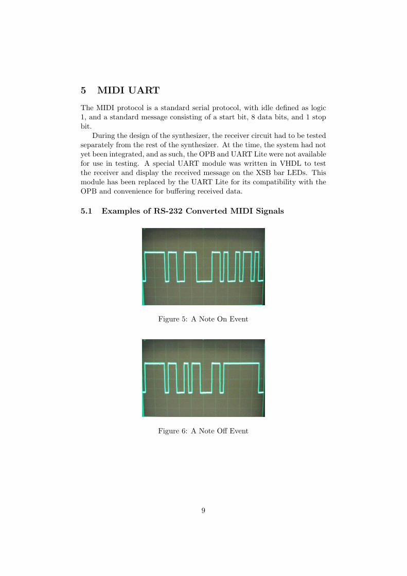
5 MIDI UART
The MIDI protocol is a standard serial protocol, with idle defined as logic1, and a standard message consisting of a start bit, 8 data bits, and 1 stopbit.
During the design of the synthesizer, the receiver circuit had to be testedseparately from the rest of the synthesizer. At the time, the system had notyet been integrated, and as such, the OPB and UART Lite were not availablefor use in testing. A special UART module was written in VHDL to testthe receiver and display the received message on the XSB bar LEDs. Thismodule has been replaced by the UART Lite for its compatibility with theOPB and convenience for buffering received data.
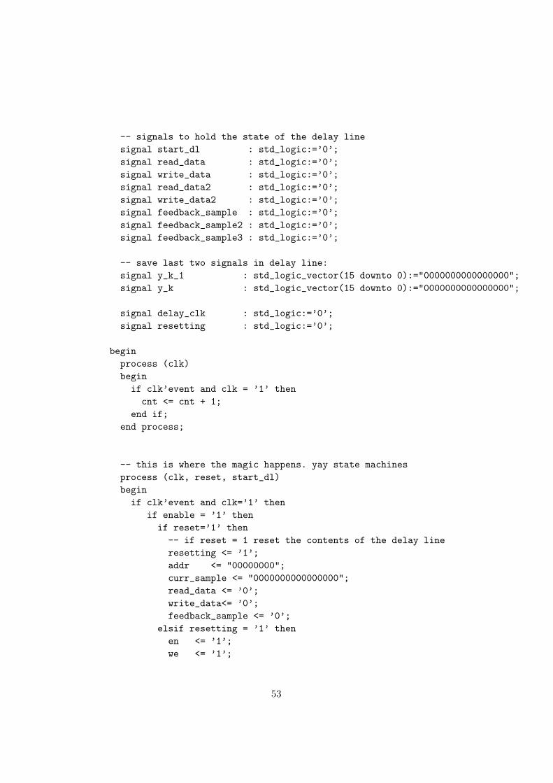
5.1 Examples of RS-232 Converted MIDI Signals
Figure 5: A Note On Event
Figure 6: A Note Off Event
9

Figure 7: A Program Change Event
10

Table 3: MIDI events handled by our synthesizerEvent Type Status Byte Data Byte 1 Data Byte 2
Note On 1001nnnn 0kkkkkkk 0vvvvvvvNote Off 1001nnnn 0kkkkkkk 00000000
Program Change 1100nnnn 0ppppppp
6 Computer Software
This module acts as the bridge between the MIDI interface and our hard-ware synthesizers. It interprets the MIDI signals and translates them intocommands for the FM and waveguide synthesizers. This accomplished insidean infinite loop in which the UART Lite is polled to check if there is a newbyte of MIDI data available in the receive FIFO. We were able to get awaywith polling the UART instead of using interrupts because the UART Liteperipheral includes a 16 byte receive FIFO which is a large enough buffer toallow the loop to poll it fast enough and not miss incoming data.
Each MIDI message consists of a status byte, followed by 1 or two databytes. In our synthesizer, we are only interested in processing three MIDImessages: Note On and Note Off, which carry 2 data bytes, and ProgramChange, which contains only 1 data byte.
In the above chart, n denotes the MIDI channel, which defaults to 0for our keyboard. k denotes the number of the key. On our keyboard, thelowest note, a C, is number 36, and the highest note, also a C, only 5 octaves(61 keys) higher is 96. v is the velocity which is always constant since ourkeyboard is not velocity sensitive. This byte is effectively ignored by oursynthesizer. p is the number of the new program. Our synthesizer has 11programs, numbered 0 through 10. Any other program change is ignored.Note that in MIDI, there are two ways to turn off a note: A Note On eventwith velocity zero, or with a different status byte which indicates a Note Offevent.
Once the correct number of data bytes are received the message is in-terpreted and translated into commands for the FM and waveguide synthe-sizers. This is accomplished by writing to memory mapped registers insidethe opb synth peripheral we created. The computer software module is alsoresponsible for keeping track of the number of active notes since there area limited number of voices available (6) to the FM synth and the digitalwaveguide.
Whenever a note on message is received, the controlling software assignsthe note to the next available voice. If none are available, the event isignored. Similarly, when a note off event is received the voice correspondingto that key is turned off (it is assumed that a note off will only come if a noteon message for the same key came sometime earlier). Lookup tables for thetwo different synthesizers were created to facilitate quick translation from
11

key number to delay line length for the waveguide or ωc for the FM synth.Finally, program change messages control which synthesizer is in use andwhich FM patch is selected. As recommended by the MIDI specification4,all active notes are turned off when a program change event is received.
7 Integration with the Microblaze CPU
In order to have the C code running on the Microblaze control the hardwaresynthesizers we created an OPB peripheral, called opb synth, containingmemory mapped registers that are mapped to the control signals for thedifferent synthesizers. This peripheral includes the audio out modules aswell as six waveguide modules and the fm synth module (which also supportssix voices). The output of each waveguide is summed with an appropriatelylarge accumulator (19 bits) to mix all six signals. The FM modules doesthe mixing internally. In addition to control signals for the voices of the twosynthesizers, a synthesizer select signal is made available to the software toensure that only one synthesizer is in use at one time.
4MIDI 1.0 Detailed Specification, The International MIDI Association, 1990
12

Address Bits Name Description0xFEFF0310 0 WG1 EN enable signal for waveguide 10xFEFF0311 0 WG1 RST reset signal for waveguide 10xFEFF0312 0-7 WG1 LEN delay line length for waveguide 10xFEFF0320 0 WG2 EN enable signal for waveguide 20xFEFF0321 0 WG2 RST reset signal for waveguide 20xFEFF0322 0-7 WG2 LEN delay line length for waveguide 20xFEFF0330 0 WG3 EN enable signal for waveguide 30xFEFF0331 0 WG3 RST reset signal for waveguide 30xFEFF0332 0-7 WG3 LEN delay line length for waveguide 30xFEFF0340 0 WG4 EN enable signal for waveguide 40xFEFF0341 0 WG4 RST reset signal for waveguide 40xFEFF0342 0-7 WG4 LEN delay line length for waveguide 40xFEFF0350 0 WG5 EN enable signal for waveguide 50xFEFF0351 0 WG5 RST reset signal for waveguide 50xFEFF0352 0-7 WG5 LEN delay line length for waveguide 50xFEFF0360 0 WG6 EN enable signal for waveguide 60xFEFF0361 0 WG6 RST reset signal for waveguide 60xFEFF0362 0-7 WG6 LEN delay line length for waveguide 60xFEFF0370 0 FM1 EN enable signal for FM voice 10xFEFF0372 0-31 FM1 THETA theta for FM voice 10xFEFF0380 0 FM2 EN enable signal for FM voice 20xFEFF0382 0-31 FM2 THETA theta for FM voice 20xFEFF0390 0 FM3 EN enable signal for FM voice 30xFEFF0392 0-31 FM3 THETA theta for FM voice 30xFEFF03A0 0 FM4 EN enable signal for FM voice 40xFEFF03A2 0-31 FM4 THETA theta for FM voice 40xFEFF03B0 0 FM5 EN enable signal for FM voice 50xFEFF03B2 0-31 FM5 THETA theta for FM voice 50xFEFF03C0 0 FM6 EN enable signal for FM voice 60xFEFF03C2 0-31 FM6 THETA theta for FM voice 60xFEFF03F0 0-3 FM MOD selects type of FM modulation0xFEFF03FF 0 SYNTH SEL selects synthesizer - 0 for FM synth, 1 for waveguide
Table 4: Memory mapped registers in OPB synth peripheral
13

8 Digital Waveguide Sound Synthesis
Figure 8: Digital Waveguide
8.1 Overview
The Karplus Strong algorithm5 simulates the motion of a standing waveon a rigidly terminated string. This is implemented as a digital waveguidewhich consists of a delay line whose output is filtered and fed back to theinput. The length of the delay line, N , determines the length of the ’string’,and thus the output frequency. With the correct loop filter, H(z), andappropriate input, the basic string sound can be augmented to sound like aspecific stringed instrument.
8.2 Definitions
N = fs
desiredfrequency . This needs to be varied depending on the desired note.H(z) - Loop filter that shapes the waveform over time, providing frequencydependent damping and shaping the note’s harmonics to mimic those of aspecific stringed instrument.
X(z) - Waveguide input - corresponds to the string excitation (eg. the’attack’ on the string). Early digital waveguides used white noise at theinput which provides a very generic string sound.
8.3 MATLAB Code
The following MATLAB code implements the Karplus Strong plucked stringsynthesis algorithm, implemented as the following filter:
Y (z) =z−N
1−H(z)z−N=
z−N
−.5z−N − .5z−N−1
function Y = ks(f, fs, length)%Karplus-Strong plucked string model% ks(f, fs, length)
5Smith, Julius O. “The Karplus Strong Algorithm”, http://www-ccrma.stanford.edu/˜jos/waveguide/Karplus Strong Algorithm.html
14

% f = frequency% fs = sampling frequency% length = time (seconds)
%length of delay line must be an integer:N = fix(fs/f);
b1 = [zeros(1, N) 1];a1 = [1 zeros(1, N-1) -.5 -.5];
Zi = rand(1, max(max(size(a1)), max(size(b1))) - 1);
Y = filter(b1, a1, X, Zi);
8.4 Implementation
We adapted the above MATLAB code into a state machine in VHDL uti-lizing a large RAM for the delay line. As with the rest of the project, eachsample is 16 bits wide. The delay line RAM is 256 x 16 bits. This gives usa minimum frequency of fs
256 ≈ 95 Hz (F2), comparable to the frequency ofthe lowest note on a guitar (E2 is 82 Hz). This uses up one of the blockRAMs available on the Xilinx FPGA.
When the waveguide is enabled (and not resetting), the state machinecycles through the delay line, shifting each sample down and performs feed-back at the end. This process takes about 1200 clock cycles per sample inthe worst case (for a delay line of length 256) which meets the requirementsof the system’s 24.414 kHz sampling rate. The only input needed for thismodule will be the length of the delay line, as well as enable and reset (usedto reinitialize the delay line) signals.
To reduce complexity and eliminate the need for multipliers, we decidedto use a simple low pass filter for H(z):
H(z) = −.5 ∗ (1 + z−1)
This filter will pass low frequencies (fc = fs/4 = 6103.5 Hz) with slight at-tenuation, so high frequency harmonics will be attenuated quickly. The re-sulting frequency dependent dampening effect also results in high frequencynotes decaying faster than low frequency notes, as with a real instrument.The problem with this H(z) is that for frequencies less than about 1 kHzthe gain is very close to unity. So while a note’s higher order harmonicswill die away realistically, the fundamental for notes in lower octaves willdie away very slowly.
We also had to take some shortcuts in choosing an appropriate excitationsignal. In order to accurately model an acoustic guitar, as was our initial
15

intention, the length of this signal would need to be many thousand sampleslong6. Due to the limited resources available on the FPGA (each block RAMcan only hold 256 16 bit samples) it proved to be impossible to include alookup table for the excitation signal in our design. Instead we used a shorterwhite noise excitation signal that consumes fewer resources.
Since we were unable to use the more complex waveguide documentedin our design document, we implemented the Karplus-Strong plucked stringsynthesis algorithm, based on a simple low pass loop filter and a white noiseexcitation signal.
The final shortcoming of the waveguide is that it is not perfectly in tunefor very high frequencies. This is because the fundamental frequency ofthe waveguide’s output is inversely proportional to the length of the delayline (N) and N is rarely an integer. So for high frequency notes, whichrequire short delay lines, the fractional part of N becomes very significant.In order to ensure that each note is in tune, we would need to implement afractional delay corresponding to a noninteger N . To do this we would needto use an interpolation filter, who’s coefficients also vary with N . Given thelimited space on the FPGA and the complexity of doing complex arithmeticin hardware, we decided that it would be too difficult to compute thesecoefficients on the fly. Therefore, we only support integer valued N , so somenotes are slightly out of tune. This and our maximum delay line lengthof 256 required us to only support a subset of notes available in the MIDIspecification with the waveguide synthesizer. To ensure that we only playnotes that are in tune, we ignore any MIDI events on keys greater than 94and less than 43. This corresponds to the 5 lowest and the 2 highest keyson the MIDI controller we are using.
While we had to take some shortcuts to reduce complexity and keep thedesign small enough, overall the sound is satisfactory and in tune. While itsounds slightly artificial, it still has a realistic sounding attack and decay.
9 FM Synthesis
FM Synthesis is a technique for generating sounds with rich harmonic con-tent with relatively low computational expense. With the right choice ofcarrier and modulating signals, different musical sounds and tones can becreated to great effect. We have implemented several different modulationschemes to produce 10 different FM sounds.
6Weiss, Ron and Steven Sanders“Synthesizing a Guitar Using Physical Modeling Tech-niques” http://www1.cs.columbia.edu/˜ronw/dsp/
16

9.1 Mathematical Basis
The basic FM equation is:
x(t) = A(t) cos(
ωct + I(t) cos(ωmt + φm) + φc
)A(t) is the amplitude envelope, and in the simplest case may be set toa constant. I(t) controls the depth of the modulation. It may also beconstant, and its exact value is not critical. A higher value produces a widermodulation range which creates a much more dramatic sweep in frequency.ωc and ωm are the carrier and modulating frequencies, respectively. It isthe ratio of those two quantities that determines the ‘flavor’ of the sound.Adjusting this ratio can generate musical sounds that range in type fromtrumpets and brass, to woodwinds, and more.
9.2 Implementation
In our project, we use a VHDL hardware module to perform the aforemen-tioned computations. Sine waves of different frequencies will be generatedfrom ROM containing the value of cos(x) for many values of x. The ROMcontains 256 samples corresponding to a full cosine period, which was exper-imentally determined to be mostly adequate for our purposes. It producesadequate fidelity sound, and easily fits on the FPGA. The same ROM canbe used to generate sinusoids of arbitrary frequency by indexing the ROMat position floor(f ∗ x), where f is the normalized frequency, representedas a fixed point two’s complement number. The decimal truncation is re-quired due to the finite size of the cosine ROM. The quantization of the sinefunction produces high frequency noise, but it inaudible.
9.3 Computational Complexity and Polyphony
Any good synthesizer has the ability to produce multiple tones simultane-ously. To see if this is possible with our system, we must discuss timing.As discussed earlier, a new sample of audio output must be prepared foroutput once every 2048 cycles. In our preliminary tests, we found that gen-erating the next sample of a simple sine wave could be done in as few astwo clock cycles, and that adding additional sinusoids to the mix requiredan additional 3 clock cycles per sinusoid. For FM synthesis, more steps areinvolved. These include multiple accesses of the cosine ROM per voice, aswell as adding correct multiples of the cosine values to the carrier frequency.
To generate a sample, the cosine ROM must be accessed six times pervoice in every 2048 clock cycles. The first three cycles access ROM for themodulation frequency and set the next value of x for that wave. The secondthree cycles access the ROM for the carrier frequency (which is offset, basedon the value of the modulation frequency). The value of the sample is then
17

stored and the value for x for the voice is incremented. Once every 2048cycles, all the voice samples are added and output to the audio out module.
The values for x of each voice’s modulation and carrier are incrementedeach iteration by constants that determines the frequencies. This works be-cause the constant determines how ’fast’ we step through the cosine ROM,which in effect stretches or shrinks the cosine wave to achieve different fre-quency waves. The constants are stored as fixed point decimal numbers,and as they are used to increment the running sum for x, the integer partis used to index the ROM, allowing us to step through the ROM at arbi-trary frequencies (although as the frequencies get very high, the relativelylow resolution of the ROM begins to become apparent. This only happensat very high frequencies though, toward the last 2 or 3 keys on the our 61key keyboard.) The constants for the carrier waves are directly determinedfrom the frequency (in Hz) and fed into the module as inputs, which in turndetermine the modulation constants. The carrier frequencies determine themodulation frequency constants in conjunction with the CToM input of thefm synth module. This input is used to select a carrier to modulation ra-tio so that we can choose different instrument types by changing the inputvalue.
The fm synth module currently has support for six simultaneous voices,each of which is controlled by its own state machine. The state machinesare controlled by individual voice enables which are in turn controlled bythe MIDI control program through the UART.
10 Audio Output Module
10.1 General Description
This module reads a 16 bit sample from its input, and outputs it one bitat a time to the onboard DAC. The onboard DAC expects stereo audio intwo channels. To produce a mono signal, we must output the 16 bit sampletwo consecutive times - once for the left and once for the right. The DACalso expects sound samples to arrive at 48.8kHz. We have chosen to supportaudio at 24.4kHz to give adequate signal processing time in between samplesas demanded by the digital waveguide algorithm. We therefore repeat eachsample an additional two times, or four times total, in order to halve thesampling frequency and produce mono sound.
10.2 Implementation
The DAC requires 3 clock signals.MCLK is a 12.5 MHz ’master clock.’BCLK is a 1.5625 MHz clock (this is the serial clock, which determines
how fast the sample bits are output to the DAC).
18

LRCK is derived by dividing down the BCLK, to obtain a 48.828 khzclock. (1.5625
25 MHz = 48.828 kHz)This is used by the DAC to time between individual left and right audio
signals. However we will generating monoaural sound, so we will be produc-ing 24 samples per second by holding each sample for twice as long in theshift register. Every 16 cycles of BCLK, LRCK shifts to indicate that a new
Figure 9: Timing for the Audio Codec
sample is being output. The STDI line represents how the highest order bitof each sample is output first, followed by the next 15, one at each BLCKcycle.
11 Example Instrument Waveforms
The following figures try to show what a typical waveform for each instru-ment (program) looks like on our synthesizer. The figures are intended toprovide a general shape of the waveform for each instrument, and do notsuggest anything about the amplitude or frequency of the sound. The signalwas conditioned prior to viewing on the oscilloscope with a first order seriesRC lowpass filter to attenuate noise at the frequency of the DAC, which is24.414 kHz. This frequency is not audible by our ears, and is consequentlynot part of the sound.
Figure 10: A Karplus Strong Waveform
19

Figure 11: A Pure Sine Waveform
Figure 12: A Weird Waveform
Figure 13: A Too Much Vibrato Waveform
Figure 14: A Trumpet Waveform
20

Figure 15: An Electric Guitar I Waveform
Figure 16: A Clarinet Waveform
Figure 17: An Electric Guitar II Waveform
Figure 18: A Cello Waveform
21

Figure 19: A Metallic Organ Waveform
Figure 20: A Carnival Waveform
22

Part III
Conclusions
12 Who Did What?
• Audio Out Module - Gabriel Glaser
• Waveguide - Ron Weiss, Gabriel Glaser
• FM Synthesizer - Scott Arfin, Gabriel Glaser
• MIDI RS-232 Adapter/Test UART - Scott Arfin
• OPB Peripheral - Ron Weiss
• C Code - Ron Weiss
13 Lessons Learned
13.1 Scott
I learned about the design and integration of a large system. In my trainingin analog circuits courses, I frequently had to analyze and design circuitsthat did tasks that we take for granted in an embedded system. I reliedon device equations and circuits analysis techniques to gain intuition andunderstanding at a very low level. TerrorMouse has been the largest andmost complicated project I have ever worked on during my studies, and Ilearned that on a large project, I cannot always achieve understanding at thelowest possible level, or reinvent the wheel every time I need to add the nextfunction or feature. It’s a different style of designing from what I am usedto, and getting used to this kind of black box, interface based abstraction inorder to put a large system with several parts together has been an importantlearning experience for me. I have also come to understand the beauty of theembedded system as a concept. With the flexibility of designing in hardwareand software, a designer can achieve a best of both worlds solution. I feel weaccomplished this in TerrorMouse, with modules requiring excellent timingaccuracy and speed, such as the FM and Waveguide synthesizers and MIDIreceiver in hardware, and the overall control system in software. Because ofthe way our design is integrated, many modifications to our design can bemade quickly and easily in the software rather than the hardware.
13.2 Gabe
Large consideration should put into sheer amount and complexity of logicfrom the very beginning stages of a project in embedded system, as we ran
23

into significant issues as we began to fill the board to capacity. This intro-duced very unpredictable behavior, probably due to the increased difficultythat the FPGA algorithm encounters at very high usage levels.
It is important not to think of VHDL as a language of programming, butas a language of design. It is far easier to efficiently design in VHDL withthe mindset that you are ’describing’ a circuit, and not coding an algorithm,per say.
Simulation is key to effectively debugging VHDL code quickly. whiletrial and error is possible, and LED indicators help, it is very useful to seeindividual signals as they change while trying to examine circuit behavior.
13.3 Ron
While working on this project I learned to appreciate the value of gooddocumentation more than ever. The only way we were able to create an OPBperipheral to integrate our hardware with C code running on the Microblazewas by reading other people’s code and the Xilinx documentation on theclass website. The code from the early labs was essential to this. Similarlyaccess to the MIDI spec was key to allowing us to talk to the keyboard.Open standards are good.
Even though its utility was downplayed in class, one thing that reallyhelped in VHDL development was the use of a simulator for debugging pur-poses. Given our limited exposure to HDLs before this class it was sometimesdifficult for us to write code that synthesized the way we expected. We usedthe Sonata VHDL compiler/simulator (http://www.symphonyeda.com/) tohelp debug the more complex state machines used in the different synthe-sizers.
Finally, as with all other projects, they key to success lies in startingearly. Our group began work on the project almost immediately. I hadbasic VHDL code for the waveguide written during spring break. It is onlyby starting early and steadily working on TerrorMouse that we were able tofinish it about two weeks before it was due, thus avoiding sleepless nights inthe lab with the rest of the class.
14 Future Work
There are a number of areas in which we could improve TerrorMouse in thefuture:
• Interrupts - To ensure that the synthesizer never missed any incomingmessages, it is important to properly buffer whatever comes into theUART Lite. As it stands now, our C code is just an infinite loop thatconstantly polls the UART’s receive FIFO for new data. While thishas worked for us in practice, a better solution would be to implement
24

interrupts and have a specialized interrupt handler that buffers anyincoming data. This way we do not have to rely on the limited size ofthe UART Lite’s FIFO and can better ensure that we do not miss anydata during processing. This becomes especially important if we wantto support additional MIDI messages which would further increaseprocessing time.
• Waveguide Synthesizer - We decided to implement a simplified versionof our original design for the waveguide synth. An improved versioncould implement the acoustic guitar model describe in http://www.cs.columbia.edu/˜ronw/dsp/.This includes implementing a more complex loop filter and using thecorrect excitation signal for the instrument.
• FM Synthesizer - While we were able to create many different soundsusing this algorithm, we barely scratched the surface in terms of themany different kinds of modulation. Specifically, we did not allow fortime-varying I(t), which would open up many new sonic possibilities.In addition, the different FM patches are currently hardcoded into theVHDL code. It would be better if there was a way to allow the specificparameters to be passed in via software to allow maximal customiz-ability without having to deal with VHDL and long recompile timesfor hardware.
• MIDI Controller - Unfortunately, the only MIDI controller we wereable to procure for this project was not velocity sensitive, so we es-sentially ignored the velocity data. It would be good to modify oursynthesis algorithms to respond to the key velocity, to allow for moremusical expression in terms of dynamics.
Part IV
Code Listings
15 Configuration Files
15.1 system.mss
PARAMETER VERSION = 2.0.0PARAMETER HW_SPEC_FILE = system.mhs
BEGIN PROCESSORPARAMETER HW_INSTANCE = mymicroblazePARAMETER DRIVER_NAME = cpuPARAMETER DRIVER_VER = 1.00.a
25

PARAMETER EXECUTABLE = hello_world.elfPARAMETER COMPILER = microblaze-gccPARAMETER ARCHIVER = microblaze-arPARAMETER DEFAULT_INIT = EXECUTABLEPARAMETER STDIN = myuartPARAMETER STDOUT = myuartEND
BEGIN DRIVERPARAMETER HW_INSTANCE = lmb_lmb_bram_if_cntlr_0PARAMETER DRIVER_NAME = genericPARAMETER DRIVER_VER = 1.00.aEND
15.2 system.mhs
# ParametersPARAMETER VERSION = 2.0.0
# Global Ports
PORT FPGA_CLK1 = FPGA_CLK1, DIR = INPORT RS232_TD = RS232_TD, DIR=OUTPORT RS232_RD = RS232_RD, DIR=IN
PORT RIGHT_LED = RIGHT_LED, DIR = OUT, VEC = [7:0]PORT LEFT_LED = LEFT_LED, DIR = OUT, VEC = [7:0]PORT BAR_LED = BAR_LED, DIR = OUT, VEC = [9:0]
PORT AU_CSN_N = AU_CSN_N, DIR=OUTPORT AU_BCLK = AU_BCLK, DIR=OUTPORT AU_MCLK = AU_MCLK, DIR=OUTPORT AU_LRCK = AU_LRCK, DIR=OUTPORT AU_SDTI = AU_SDTI, DIR=OUTPORT AU_SDTO0 = AU_SDTO0, DIR=IN
# Sub Components
BEGIN microblazePARAMETER INSTANCE = mymicroblazePARAMETER HW_VER = 2.00.aPARAMETER C_USE_BARREL = 1PARAMETER C_USE_ICACHE = 0
26

PORT Clk = sys_clkPORT Reset = fpga_reset# PORT Interrupt = intrBUS_INTERFACE DLMB = d_lmbBUS_INTERFACE ILMB = i_lmbBUS_INTERFACE DOPB = myopb_busBUS_INTERFACE IOPB = myopb_busEND
BEGIN bram_blockPARAMETER INSTANCE = bramPARAMETER HW_VER = 1.00.aBUS_INTERFACE PORTA = conn_0BUS_INTERFACE PORTB = conn_1END
BEGIN clkgenPARAMETER INSTANCE = clkgen_0PARAMETER HW_VER = 1.00.aPORT FPGA_CLK1 = FPGA_CLK1PORT sys_clk = sys_clkPORT pixel_clock = pixel_clockPORT fpga_reset = fpga_resetEND
BEGIN lmb_lmb_bram_if_cntlrPARAMETER INSTANCE = lmb_lmb_bram_if_cntlr_0PARAMETER HW_VER = 1.00.aPARAMETER C_BASEADDR = 0x00000000PARAMETER C_HIGHADDR = 0x00000FFFBUS_INTERFACE DLMB = d_lmbBUS_INTERFACE ILMB = i_lmbBUS_INTERFACE PORTA = conn_0BUS_INTERFACE PORTB = conn_1END
BEGIN opb_v20PARAMETER INSTANCE = myopb_busPARAMETER HW_VER = 1.10.aPARAMETER C_DYNAM_PRIORITY = 0PARAMETER C_REG_GRANTS = 0PARAMETER C_PARK = 0PARAMETER C_PROC_INTRFCE = 0PARAMETER C_DEV_BLK_ID = 0
27

PARAMETER C_DEV_MIR_ENABLE = 0PARAMETER C_BASEADDR = 0x0fff1000PARAMETER C_HIGHADDR = 0x0fff10ffPORT SYS_Rst = fpga_resetPORT OPB_Clk = sys_clkEND
BEGIN lmb_v10PARAMETER INSTANCE = d_lmbPARAMETER HW_VER = 1.00.aPORT LMB_Clk = sys_clkPORT SYS_Rst = fpga_resetEND
BEGIN lmb_v10PARAMETER INSTANCE = i_lmbPARAMETER HW_VER = 1.00.aPORT LMB_Clk = sys_clkPORT SYS_Rst = fpga_resetEND
BEGIN opb_synthPARAMETER INSTANCE = mysynthPARAMETER HW_VER = 1.00.aPARAMETER C_BASEADDR = 0xFEFF0300PARAMETER C_HIGHADDR = 0xFEFF03ffPORT OPB_Clk = sys_clkBUS_INTERFACE SOPB = myopb_busPORT FPGA_clk = sys_clkEND
BEGIN opb_uartlitePARAMETER INSTANCE = myuartPARAMETER HW_VER = 1.00.bPARAMETER C_CLK_FREQ = 50_000_000PARAMETER C_USE_PARITY = 0PARAMETER C_BAUDRATE = 31_250PARAMETER C_DATA_BITS = 8PARAMETER C_BASEADDR = 0xFEFF0100PARAMETER C_HIGHADDR = 0xFEFF01FFPORT OPB_Clk = sys_clkBUS_INTERFACE SOPB = myopb_busPORT RX=RS232_RDPORT TX=RS232_TD
28

END
BEGIN opb_xsbledsPARAMETER INSTANCE = ledsPARAMETER HW_VER = 1.00.aPARAMETER C_BASEADDR = 0xFEFF0200PARAMETER C_HIGHADDR = 0xFEFF02ffPORT OPB_Clk = sys_clkBUS_INTERFACE SOPB = myopb_busPORT RIGHT_LED = RIGHT_LEDPORT LEFT_LED = LEFT_LEDPORT BAR_LED = BAR_LEDEND
15.3 system.ucf
#net sys_clk period = 18.000;
net FPGA_CLK1 loc="p77";
net RS232_TD loc="p71";net RS232_RD loc="p73";
net LEFT_LED<0> loc="p153";net LEFT_LED<1> loc="p145";net LEFT_LED<2> loc="p141";net LEFT_LED<3> loc="p135";net LEFT_LED<4> loc="p126";net LEFT_LED<5> loc="p120";net LEFT_LED<6> loc="p116";net LEFT_LED<7> loc="p108";
net RIGHT_LED<0> loc="p127";net RIGHT_LED<1> loc="p129";net RIGHT_LED<2> loc="p132";net RIGHT_LED<3> loc="p133";net RIGHT_LED<4> loc="p134";net RIGHT_LED<5> loc="p136";net RIGHT_LED<6> loc="p138";net RIGHT_LED<7> loc="p139";
net BAR_LED<0> loc="p83";net BAR_LED<1> loc="p84";
29

net BAR_LED<2> loc="p86";net BAR_LED<3> loc="p87";net BAR_LED<4> loc="p88";net BAR_LED<5> loc="p89";net BAR_LED<6> loc="p93";net BAR_LED<7> loc="p94";net BAR_LED<8> loc="p140";net BAR_LED<9> loc="p146";
net AU_CSN_N loc="p165";net AU_BCLK loc="p166";net AU_MCLK loc="p167";net AU_LRCK loc="p168";net AU_SDTI loc="p169";net AU_SDTO0 loc="p173";
15.4 Makefile
SYSTEM = system
MHSFILE = system.mhs
MSSFILE = system.mss
MVSFILE = system.mvs
FPGA_ARCH = spartan2e
DEVICE = xc2s300epq208-6
LANGUAGE = verilog
PLATGEN_OPTIONS = -p $(FPGA_ARCH) -lang $(LANGUAGE)
LIBGEN_OPTIONS = -p $(FPGA_ARCH) $(MYMICROBLAZE_LIBG_OPT)
# Paths
XILINX = /usr/cad/xilinx/ise6.1iISEBINDIR = $(XILINX)/bin/linISEENVCMDS = LD_LIBRARY_PATH=$(ISEBINDIR) XILINX=$(XILINX) PATH=$(ISEBINDIR)
XILINX_EDK = /usr/cad/xilinx/edk3.2
30

MICROBLAZE = /usr/cad/xilinx/gnuMBBINDIR = $(MICROBLAZE)/binXESSBINDIR = /usr/cad/xess/bin
# Executables
XST = $(ISEENVCMDS) $(ISEBINDIR)/xstXFLOW = $(ISEENVCMDS) $(ISEBINDIR)/xflowBITGEN = $(ISEENVCMDS) $(ISEBINDIR)/bitgenXSLOAD = $(XESSBINDIR)/xsloadXESS_BOARD = XSB-300E
MYMICROBLAZE_CC = $(MBBINDIR)/microblaze-gccMYMICROBLAZE_CC_SIZE = $(MBBINDIR)/microblaze-size
SIM_COMP_SCRIPT = simulation/$(SYSTEM)_comp.do
SIM_INIT_SCRIPT = simulation/$(SYSTEM)_init.do
SIMGEN_OPTIONS = -p $(FPGA_ARCH) -lang $(LANGUAGE)
MYMICROBLAZE_OUTPUT = hello_world.elf
LIBRARIES = mymicroblaze/lib/libxil.a
# External Targets
all:@echo "Makefile to build a Microprocessor system :"@echo "Run make with any of the following targets"@echo " make libs : Configures the sw libraries for this system"@echo " make program : Compiles the program sources for all the processor instances"@echo " make netlist : Generates the netlist for this system ($(SYSTEM))"@echo " make bits : Runs Implementation tools to generate the bitstream"@echo " make init_bram: Initializes bitstream with BRAM data"@echo " make download : Downloads the bitstream onto the board"@echo " make sim : Generates simulation models and runs simulator"@echo " make netlistclean: Deletes netlist"@echo " make hwclean : Deletes implementation dir"@echo " make libsclean: Deletes sw libraries"@echo " make programclean: Deletes compiled ELF files"@echo " make simclean : Deletes simulation dir"@echo " make clean : Deletes all generated files/directories"@echo " "
31

@echo " make <target> : (Default)"@echo " Creates a Microprocessor system using default initializations"@echo " specified for each processor in MSS file"
bits: implementation/$(SYSTEM).bit
ace: implementation/$(SYSTEM).ace
netlist: implementation/$(SYSTEM).ngc
libs: $(LIBRARIES)
program:: $(MYMICROBLAZE_OUTPUT)
download: implementation/download.bit dummy@echo "*********************************************"@echo "Downloading Bitstream onto the target board"@echo "*********************************************"$(XSLOAD) -fpga -b $(XESS_BOARD) implementation/download.bit
init_bram: implementation/download.bit
clean: hwclean libsclean programclean simcleanrm -f bram_init.shrm -f _impact.cmd
hwclean: netlistcleanrm -rf implementation synthesis xst hdlrm -rf xst.srp $(SYSTEM).srp
netlistclean:rm -f implementation/$(SYSTEM).bit implementation/$(SYSTEM).ncd implementation/$(SYSTEM)_bd.bmm
simclean:rm -rf simulation
libsclean: MYMICROBLAZE_LIBSCLEAN
programclean: MYMICROBLAZE_PROGRAMCLEAN
################################################################## TARGETS/MACROS FOR PROCESSOR MYMICROBLAZE#################################################################
32

#MYMICROBLAZE_SOURCES=c_source_files/bintree#MYMICROBLAZE_CSRC=patsubst(%, %.c, $(MYMICROBLAZE_SOURCES)#MYMICROBLAZE_OBJS=patsubst(%, %.o, $(MYMICROBLAZE_SOURCES))
#MYMICROBLAZE_CSRC=c_source_files/bintree.cMYMICROBLAZE_OBJS=c_source_files/hello.o
MYMICROBLAZE_MODE = executable
# CC1MYMICROBLAZE_CC_CFLAGS =MYMICROBLAZE_CC_OPT = -O3 #-mxl-gp-optMYMICROBLAZE_CC_DEBUG_FLAG =# -gstabsMYMICROBLAZE_INCLUDES = -I./mymicroblaze/include/ # -IMYMICROBLAZE_CFLAGS = \$(MYMICROBLAZE_CC_CFLAGS)\-mxl-barrel-shift \$(MYMICROBLAZE_CC_OPT) \$(MYMICROBLAZE_CC_DEBUG_FLAG) \$(MYMICROBLAZE_INCLUDES)
# LDMYMICROBLAZE_LD_FLAGS =# -Wl,-M#MYMICROBLAZE_LINKER_SCRIPT = -Wl,-T -Wl,mylinkscriptMYMICROBLAZE_LINKER_SCRIPT =MYMICROBLAZE_LIBPATH = -L./mymicroblaze/lib/ # -LMYMICROBLAZE_CC_START_ADDR_FLAG= -Wl,-defsym -Wl,_TEXT_START_ADDR=0x00000000MYMICROBLAZE_CC_STACK_SIZE_FLAG= -Wl,-defsym -Wl,_STACK_SIZE=0x200MYMICROBLAZE_LFLAGS = \-xl-mode-$(MYMICROBLAZE_MODE) \$(MYMICROBLAZE_LD_FLAGS) \$(MYMICROBLAZE_LINKER_SCRIPT) \$(MYMICROBLAZE_LIBPATH) \$(MYMICROBLAZE_CC_START_ADDR_FLAG) \$(MYMICROBLAZE_CC_STACK_SIZE_FLAG)
#here is the compilation$(MYMICROBLAZE_OBJS) : %.o : %.cecho $<PATH=$(MBBINDIR) $(MYMICROBLAZE_CC) $(MYMICROBLAZE_CFLAGS) -c $< -o $@
#here is the linking
33

$(MYMICROBLAZE_OUTPUT) : $(LIBRARIES) $(MYMICROBLAZE_OBJS)PATH=$(MBBINDIR) $(MYMICROBLAZE_CC) $(MYMICROBLAZE_LFLAGS) \$(MYMICROBLAZE_OBJS) -o $(MYMICROBLAZE_OUTPUT)
$(MYMICROBLAZE_CC_SIZE) $(MYMICROBLAZE_OUTPUT)
MYMICROBLAZE_LIBSCLEAN:rm -rf mymicroblaze/lib/
MYMICROBLAZE_PROGRAMCLEAN:rm -f $(MYMICROBLAZE_OUTPUT)
################################################################## TARGETS/MACROS FOR XILINX IMPLEMENTATION FLOW#################################################################
implementation/download.bit: implementation/$(SYSTEM).bit $(MYMICROBLAZE_OUTPUT)@cp -f implementation/$(SYSTEM)_bd.bmm .@echo "*********************************************"@echo "Initializing BRAM contents of the bitstream"@echo "*********************************************"$(ISEENVCMDS) ./bram_init.sh@rm -f $(SYSTEM)_bd.bmm
implementation/$(SYSTEM).bit: implementation/$(SYSTEM).ngc etc/fast_runtime.opt etc/bitgen.ut data/$(SYSTEM).ucf@echo "Copying Xilinx Implementation tool scripts.."@cp -f etc/bitgen.ut implementation/@cp -f etc/fast_runtime.opt implementation/@cp -f data/$(SYSTEM).ucf implementation/$(SYSTEM).ucf@echo "*********************************************"@echo "Running Xilinx Implementation tools.."@echo "*********************************************"$(XFLOW) -wd implementation -p $(DEVICE) -implement fast_runtime.opt $(SYSTEM).ngccd implementation; $(BITGEN) -f bitgen.ut $(SYSTEM)
implementation/$(SYSTEM).ngc: $(MHSFILE)@echo "*********************************************"@echo "Creating system netlist for hardware specification.."@echo "*********************************************"XILINX=$(XILINX) XILINX_EDK=$(XILINX_EDK) perl -I $(XILINX_EDK)/bin/nt/perl5lib $(XILINX_EDK)/bin/nt/platgen.pl $(PLATGEN_OPTIONS) -st xst $(MHSFILE)echo "Running iSE XST..."perl synth_modules.pl <synthesis/xst.scr >xst.scr$(XST) -ifn xst.scr
34

rm -r xst xst.scr$(XST) -ifn synthesis/$(SYSTEM).scr
$(LIBRARIES): $(MHSFILE) $(MSSFILE)@echo "*********************************************"@echo "Creating software libraries..."@echo "*********************************************"PATH=$$PATH:$(MBBINDIR) XILINX=$(XILINX) XILINX_EDK=$(XILINX_EDK) perl -I $(XILINX_EDK)/bin/nt/perl5lib $(XILINX_EDK)/bin/nt/libgen.pl $(LIBGEN_OPTIONS) $(MSSFILE)
$(SIM_INIT_SCRIPT) : $(SIM_COMP_SCRIPT) $(MYMICROBLAZE_OUTPUT)@echo "*********************************************"@echo "Initializing simulation models..."@echo "*********************************************"simgen $(SIMGEN_OPTIONS) -i $(MVSFILE)
$(SIM_COMP_SCRIPT) : simulation/$(SYSTEM)_sim.bmm $(MVSFILE) __xps/simgen.opt@echo "*********************************************"@echo "Creating simulation models..."@echo "*********************************************"simgen $(SIMGEN_OPTIONS) $(MVSFILE)
simulation/$(SYSTEM)_sim.bmm: implementation/$(SYSTEM).bitplatgen -bmm $(PLATGEN_OPTIONS) -st xst $(SYSTEM).mhs
dummy:@echo ""
16 C Code
16.1 hello.c
//EE4840 - TerrorMouse MIDI Synthesizer - main program//by Ron Weiss
#include "xbasic_types.h"#include "xio.h"//#include "xintc_l.h"//#include "xparameters.h"
#include "synth.h"#include "wglookup.h"#include "fmlookup.h"
35

#define UART_ADDR 0xFEFF0100#define UART_RXFIFO 0xFEFF0100#define UART_TXFIFO 0xFEFF0104#define UART_STATUS 0xFEFF0108#define UART_CTRL 0xFEFF010C
main(){
unsigned int x;unsigned char byte = 0;unsigned char status = 0, databytes = 0;unsigned char data[2] = {0, 0};unsigned char key = 0, vel = 0;unsigned char synth_sel = 0, fm_mod = 0, fm_octave = 0;
unsigned char wgs[WG_VOICES] = {0, 0, 0, 0, 0, 0};unsigned char fms[FM_VOICES] = {0, 0, 0, 0, 0, 0};
/** Initialization*/
//shut off LEDSfor(x = 0; x < 256; x += 4)
XIo_Out32(LED_ADDR+x, 0);
//zero synth inputsfor(x = 0; x < 256; x += 4)
XIo_Out32(SYNTH_ADDR+x, 0);
//turn on waveguide by defaultsynth_sel = SEL_WG;XIo_Out8(SYNTH_SEL, synth_sel);
//set up uartlite - disable interrupts/reset FIFOsXIo_Out32(UART_CTRL, 0);
/** The main loop - where the magic happens*/
for(;;)
36

{//wait for new byte in UART_RXFIFOif(XIo_In32(UART_STATUS) & 0x01){
byte = XIo_In32(UART_RXFIFO);
//first bit of status message is 1if(byte >> 7){
status = byte >> 4;data[0] = 0;data[1] = 0;databytes = 0;
}else{
data[databytes] = byte;databytes++;
}
//show something on the leds (key number or program number for our//purposes)XIo_Out8(LED_ADDR+8, data[0]);
if(databytes == 2) //2 data byte messages{
key = data[0];vel = data[1];
switch(synth_sel){case SEL_FM:
switch(status){case MIDI_NOTEOFF:
//turn off FM voice corresponding to keyfor(x=0; x <= FM_VOICES-1; x++){
if(fms[x] == key){
fms[x] = 0;fm_off(x);break;
}
37

}break;
case MIDI_NOTEON:if(vel != 0) //note on{
//find unused fm voicefor(x=0; x <= FM_VOICES-1; x++){
if(fms[x] == 0){
fms[x] = key;fm_on(x, fm_notes[key - fm_octave]);break;
}}
}else //note off if we get note on message with vel=0{
//turn off fm voice corresponding to keyfor(x=0; x <= FM_VOICES-1; x++){
if(fms[x] == key){
fms[x] = 0;fm_off(x);break;
}}
}break;
} //switch statusbreak;
case SEL_WG:switch(status){case MIDI_NOTEOFF:
//turn off waveguide corresponding to keyfor(x=0; x <= WG_VOICES-1; x++){
if(wgs[x] == key){
wgs[x] = 0;wg_off(x);break;
38

}}break;
case MIDI_NOTEON:if(vel != 0 && key > 43 && key < 95) //note on{
//find empty waveguidefor(x=0; x <= WG_VOICES-1; x++){
if(wgs[x] == 0){
wgs[x] = key;wg_on(x, wg_notes[key]);break;
}}
}else //note off if we get note on message with velocity of zero{
//turn off waveguide corresponding to keyfor(x=0; x <= WG_VOICES-1; x++){
if(wgs[x] == key){
wgs[x] = 0;wg_off(x);break;
}}
}break;
} //switch status} //switch synth_sel
//reset registers and wait for next messagedatabytes = 0;
}//we’re only interpretting one message with only 1 data byteelse if(status == MIDI_PROG && databytes == 1){
if(data[0] == 0) //select waveguidesynth_sel = SEL_WG;
else if(data[0] <= FM_PATCHES){
39

synth_sel = SEL_FM;fm_mod = data[0] - 1;
//compensate for patches with large modulating frequency - shift down an octaveif(data[0] == 4 || data[0] == 6 || data[0] == 8 || data[0] == 10)
fm_octave = 12;else
fm_octave = 0;}XIo_Out8(SYNTH_SEL, synth_sel);XIo_Out8(FM_MOD, fm_mod);
//turn off stuck notes:for(x = 0; x <= 5; x++){
wgs[x] = 0;wg_off(x);fms[x] = 0;fm_off(x);
}
//reset registers and wait for next messagedatabytes = 0;
}} //if new byte ready
} //for}
16.2 synth.h
#define LED_ADDR 0xFEFF0200#define SYNTH_ADDR 0xFEFF0300
//synth control#define SYNTH_SEL 0xFEFF03FF //0 for fm, 1 for waveguide#define SEL_FM 0#define SEL_WG 1
//waveguides#define WG_VOICES 6#define WG_ADDR 0xFEFF0310#define WG_EN 0xFEFF0310#define WG_RST 0xFEFF0311#define WG_LEN 0xFEFF0312
40

#define wg_on(num, len) XIo_Out8(WG_LEN+((num)<<4),(len)); XIo_Out8(WG_EN+((num)<<4),1); XIo_Out8(WG_RST+((num)<<4),1); XIo_Out8(WG_RST+((num)<<4),0);#define wg_off(num) XIo_Out8(WG_EN+((num)<<4), 0);
//fm synths#define FM_PATCHES 10#define FM_VOICES 6#define FM_ADDR 0xFEFF0370#define FM_EN 0xFEFF0370#define FM_THETA 0xFEFF0372#define FM_MOD 0xFEFF03F0#define fm_on(num, theta) XIo_Out32(FM_THETA+((num)<<4), (theta)); XIo_Out8(FM_EN+((num)<<4), 1);#define fm_off(num) XIo_Out8(FM_EN+((num)<<4), 0);
//midi#define MIDI_NOTEOFF 0x8#define MIDI_NOTEON 0x9#define MIDI_PROG 0xc //program change
16.3 fmlookup.h
static unsigned int fm_notes[128] = {702, 744, 788,835, 884, 937, 993, 1052, 1114,1181, 1251, 1325, 1404, 1488, 1576,1670, 1769, 1874, 1986, 2104, 2229,2362, 2502, 2651, 2809, 2976, 3153,3340, 3539, 3749, 3972, 4209, 4459,4724, 5005, 5303, 5618, 5952, 6306,6681, 7078, 7499, 7945, 8418, 8918,9448, 10010, 10606, 11236, 11904, 12612,13362, 14157, 14999, 15891, 16836, 17837,18897, 20021, 21212, 22473, 23809, 25225,26725, 28314, 29998, 31782, 33672, 35674,37795, 40043, 42424, 44946, 47619, 50451,53451, 56629, 59996, 63564, 67344, 71348,75591, 80086, 84848, 89893, 95239, 100902,106902, 113259, 119993, 127129, 134688, 142697,151182, 160172, 169697, 179787, 190478, 201804,213804, 226518, 239987, 254258, 269377, 285395,302365, 320345, 339394, 359575, 380956, 403609,427609, 453036, 479975, 508516, 538754, 570790,604731, 640690, 678788, 719150, 761913, 807219,855219, 906073, 959951, 1017032, 1077508};
41

16.4 wglookup.h
//length = 56 (key 69) = A 440unsigned charwg_notes[128]={ 255, 255, 2830, 2670, 2520, 2380, 2240, 2120, //7
2000, 1890, 1780, 1680, 1570, 1500, 1410, 1330, //151259, 1188, 1212, 1059, 999, 943, 890, 840, //23793, 749, 707, 667, 629, 594, 561, 529, //31500, 472, 445, 420, 397, 374, 353, 333, //39315, 297, 265, 250, 236, 223, 210, 198, //47187, 177, 167, 157, 149, 140, 132, 125, //55118, 111, 105, 99, 94, 88, 83, 79, //6374, 70, 66, 62, 59, 56, 53, 50, //7147, 44, 42, 39, 37, 35, 33, 31, //7929, 28, 26, 25, 24, 22, 21, 20, //8719, 18, 17, 16, 15, 14, 13, 12, //9512, 11, 10, 9, 9, 8, 8, 7, //1037, 7, 6, 6, 6, 5, 5, 5, //1114, 4, 4, 4, 3, 3, 3, 3, //1193, 3, 2, 2, 2, 2}; //127
17 OPB Synth Peripheral
17.1 Configuration Files
17.1.1 opb synth v2 0 0.pao
################################################################# opb_core_ssp0 pao file################################################################
#lib proc_common_v1_00_b proc_common_pkg#lib proc_common_v1_00_b pselect#lib proc_common_v1_00_b or_muxcy#lib ipif_common_v1_00_a ipif_pkg#lib ipif_common_v1_00_a ipif_steer#lib opb_bus_attach_v1_00_a reset_mir#lib opb_bus_attach_v1_00_a opb_bus_attach#lib opb_ipif_ssp0_v1_00_a opb_ipif_ssp0
# --USER-- add all user core source files and change the following source to# your top level core name and library
42

lib opb_synth_v1_00_a opb_synthlib opb_synth_v1_00_a audio_outlib opb_synth_v1_00_a fm_synthlib opb_synth_v1_00_a cosine_of_thetalib opb_synth_v1_00_a waveguidelib opb_synth_v1_00_a delayline
17.1.2 opb synth v2 0 0.mpd
####################################################################### Microprocessor Peripheral Definition : generated by psfutil#####################################################################
BEGIN opb_synth, IPTYPE = PERIPHERAL, EDIF=TRUE # --USER-- change core name
BUS_INTERFACE BUS = SOPB, BUS_STD = OPB, BUS_TYPE = SLAVE
## Generics for VHDL or Parameters for VerilogPARAMETER c_baseaddr = 0xFFFFFFFF, DT = std_logic_vector, MIN_SIZE = 0xFFPARAMETER c_highaddr = 0x00000000, DT = std_logic_vector#PARAMETER c_mir_baseaddr = 0xFFFFFFFF, DT = std_logic_vector, MIN_SIZE = 0xFF#PARAMETER c_mir_highaddr = 0x00000000, DT = std_logic_vector#PARAMETER c_user_id_code = 3, DT = integer#PARAMETER c_include_mir = 0, DT = integerPARAMETER c_opb_awidth = 32, DT = integerPARAMETER c_opb_dwidth = 32, DT = integerPARAMETER c_family = spartan2e, DT = string# --USER-- Add user core parameters
## PortsPORT opb_abus = OPB_ABus, DIR = IN, VEC = [0:(c_opb_awidth-1)], BUS = SOPBPORT opb_be = OPB_BE, DIR = IN, VEC = [0:((c_opb_dwidth/8)-1)], BUS = SOPBPORT opb_clk = "", DIR = IN, BUS = SOPBPORT opb_dbus = OPB_DBus, DIR = IN, VEC = [0:(c_opb_dwidth-1)], BUS = SOPBPORT opb_rnw = OPB_RNW, DIR = IN, BUS = SOPBPORT opb_rst = OPB_Rst, DIR = IN, BUS = SOPBPORT opb_select = OPB_select, DIR = IN, BUS = SOPBPORT opb_seqaddr = OPB_seqAddr, DIR = IN, BUS = SOPBPORT sln_dbus = Sl_DBus, DIR = OUT, VEC = [0:(c_opb_dwidth-1)], BUS = SOPBPORT sln_errack = Sl_errAck, DIR = OUT, BUS = SOPB
43

PORT sln_retry = Sl_retry, DIR = OUT, BUS = SOPBPORT sln_toutsup = Sl_toutSup, DIR = OUT, BUS = SOPBPORT sln_xferack = Sl_xferAck, DIR = OUT, BUS = SOPB
# --USER-- change to user core ports--PORT led = "", DIR = OUT, VEC = [0:3]PORT FPGA_clk = FPGA_clk, DIR = IN, BUS = SOPB, SIGIS = CLK
PORT AU_CSN_N = AU_CSN_N, DIR = OUTPORT AU_BCLK = AU_BCLK, DIR = OUTPORT AU_MCLK = AU_MCLK, DIR = OUTPORT AU_LRCK = AU_LRCK, DIR = OUTPORT AU_SDTI = AU_SDTI, DIR = OUT
END
17.2 VHDL Code
17.2.1 opb synth.vhd
-- CSEEE4830 - TerrorMouse-- by Ron Weisslibrary ieee;use ieee.std_logic_1164.all;use IEEE.STD_LOGIC_ARITH.all;use IEEE.STD_LOGIC_SIGNED.all;
--------------------------------------------------------------------------------- entity-------------------------------------------------------------------------------
entity OPB_synth is --USER-- change entity namegeneric(C_BASEADDR : std_logic_vector(0 to 31) := X"FFFFFFFF";C_HIGHADDR : std_logic_vector(0 to 31) := X"00000000";C_OPB_AWIDTH : integer := 32;C_OPB_DWIDTH : integer := 32;C_FAMILY : string := "spartan2e"
);port(--Required OPB bus ports, do not add to or deleteOPB_ABus : in std_logic_vector(0 to C_OPB_AWIDTH-1);
44

OPB_BE : in std_logic_vector(0 to C_OPB_DWIDTH/8-1);OPB_Clk : in std_logic;OPB_DBus : in std_logic_vector(0 to C_OPB_DWIDTH-1);OPB_RNW : in std_logic;OPB_Rst : in std_logic;OPB_select : in std_logic;OPB_seqAddr : in std_logic;Sln_DBus : out std_logic_vector(0 to C_OPB_DWIDTH-1);Sln_errAck : out std_logic;Sln_retry : out std_logic;Sln_toutSup : out std_logic;Sln_xferAck : out std_logic;
--USER-- add user I/Os to port listFPGA_clk : in std_logic; -- FPGA clockAU_CSN_N : out std_logic;AU_BCLK : out std_logic;AU_MCLK : out std_logic;AU_LRCK : out std_logic;AU_SDTI : out std_logic
);end entity OPB_synth; --USER-- change entity name
--------------------------------------------------------------------------------- architecture-------------------------------------------------------------------------------
architecture imp of OPB_synth is --USER-- change entity name
component audio_outport (clk : in std_logic;rst : in std_logic;
sample_in : in std_logic_vector(15 downto 0);
AU_CSN_N : out std_logic;AU_BCLK : out std_logic;AU_MCLK : out std_logic;AU_LRCK : out std_logic;AU_SDTI : out std_logic);
end component;
45

component fm_synthport (
clk : in std_logic;sample_out : out std_logic_vector(15 downto 0);reset : in std_logic;
--offset inputstheta1_bres_in : in std_logic_vector(31 downto 0);theta2_bres_in : in std_logic_vector(31 downto 0);theta3_bres_in : in std_logic_vector(31 downto 0);theta4_bres_in : in std_logic_vector(31 downto 0);theta5_bres_in : in std_logic_vector(31 downto 0);theta6_bres_in : in std_logic_vector(31 downto 0);
--enablestheta1_en : in std_logic;theta2_en : in std_logic;theta3_en : in std_logic;theta4_en : in std_logic;theta5_en : in std_logic;theta6_en : in std_logic;
--c/m ratio inputcToM : in std_logic_vector(7 downto 0));
end component;
component waveguideport (
clk : in std_logic;enable : in std_logic;reset : in std_logic;length : in std_logic_vector(7 downto 0); -- length of delay linesample_out : out std_logic_vector(15 downto 0)
);end component;
signal addr : std_logic_vector(0 to 7); -- local addresssignal wdata : std_logic_vector(0 to 7);signal rnw : std_logic;signal cs, xfer : std_logic;
signal byte_data : std_logic_vector(7 downto 0);signal word_data : std_logic_vector(31 downto 0);
46

-- waveguide synth signals (6 voices)signal wg1_en : std_logic := ’1’;signal wg1_rst : std_logic := ’0’;signal wg1_len : std_logic_vector(7 downto 0) := "00000000";signal wg1_out : std_logic_vector(15 downto 0) := "0000000000000000";signal wg2_en : std_logic := ’1’;signal wg2_rst : std_logic := ’0’;signal wg2_len : std_logic_vector(7 downto 0) := "00000000";signal wg2_out : std_logic_vector(15 downto 0) := "0000000000000000";signal wg3_en : std_logic := ’1’;signal wg3_rst : std_logic := ’0’;signal wg3_len : std_logic_vector(7 downto 0) := "00000000";signal wg3_out : std_logic_vector(15 downto 0) := "0000000000000000";signal wg4_en : std_logic := ’1’;signal wg4_rst : std_logic := ’0’;signal wg4_len : std_logic_vector(7 downto 0) := "00000000";signal wg4_out : std_logic_vector(15 downto 0) := "0000000000000000";signal wg5_en : std_logic := ’1’;signal wg5_rst : std_logic := ’0’;signal wg5_len : std_logic_vector(7 downto 0) := "00000000";signal wg5_out : std_logic_vector(15 downto 0) := "0000000000000000";signal wg6_en : std_logic := ’1’;signal wg6_rst : std_logic := ’0’;signal wg6_len : std_logic_vector(7 downto 0) := "00000000";signal wg6_out : std_logic_vector(15 downto 0) := "0000000000000000";signal wg_out : std_logic_vector(18 downto 0) := "0000000000000000000";
-- fm synth signalssignal fm1_en : std_logic := ’0’;signal fm1_theta : std_logic_vector(31 downto 0);signal fm2_en : std_logic := ’0’;signal fm2_theta : std_logic_vector(31 downto 0);signal fm3_en : std_logic := ’0’;signal fm3_theta : std_logic_vector(31 downto 0);signal fm4_en : std_logic := ’0’;signal fm4_theta : std_logic_vector(31 downto 0);signal fm5_en : std_logic := ’0’;signal fm5_theta : std_logic_vector(31 downto 0);signal fm6_en : std_logic := ’0’;signal fm6_theta : std_logic_vector(31 downto 0);signal fm_mod : std_logic_vector(7 downto 0); -- which FM patchsignal fm_out : std_logic_vector(15 downto 0);
47

signal synth_sel : std_logic := ’0’; -- synth selector (0 = fm, 1 = wg);signal synth_out : std_logic_vector(15 downto 0);
beginprocess (OPB_select, OPB_ABus)beginif(OPB_select=’1’ and OPB_ABus(0 to 23)=C_BASEADDR(0 to 23)) thencs <= ’1’;
elsecs <= ’0’;
end if;end process;
-- swap bit order of databyte_data(7 downto 0) <= wdata(0 to 7);
process (OPB_Clk)beginif OPB_Clk’event and OPB_Clk = ’1’ then
rnw <= OPB_RNW;addr <= OPB_ABus(24 to 31);wdata <= OPB_DBus(0 to 7);xfer <= cs and not xfer;
word_data(31 downto 0) <= OPB_DBus(0 to 31);
if(xfer=’1’ and rnw=’0’) thencase addr is
when X"10" => wg1_en <= word_data(0);when X"11" => wg1_rst <= word_data(0);when X"12" => wg1_len <= byte_data;when X"20" => wg2_en <= byte_data(0);when X"21" => wg2_rst <= byte_data(0);when X"22" => wg2_len <= byte_data;when X"30" => wg3_en <= byte_data(0);when X"31" => wg3_rst <= byte_data(0);when X"32" => wg3_len <= byte_data;when X"40" => wg4_en <= byte_data(0);when X"41" => wg4_rst <= byte_data(0);when X"42" => wg4_len <= byte_data;when X"50" => wg5_en <= byte_data(0);when X"51" => wg5_rst <= byte_data(0);when X"52" => wg5_len <= byte_data;when X"60" => wg6_en <= byte_data(0);
48

when X"61" => wg6_rst <= byte_data(0);when X"62" => wg6_len <= byte_data;when X"70" => fm1_en <= byte_data(0);when X"72" => fm1_theta <= word_data;when X"80" => fm2_en <= word_data(0);when X"82" => fm2_theta <= word_data;when X"90" => fm3_en <= word_data(0);when X"92" => fm3_theta <= word_data;when X"a0" => fm4_en <= word_data(0);when X"a2" => fm4_theta <= word_data;when X"b0" => fm5_en <= word_data(0);when X"b2" => fm5_theta <= word_data;when X"c0" => fm6_en <= word_data(0);when X"c2" => fm6_theta <= word_data;when X"f0" => fm_mod <= byte_data;when X"ff" => synth_sel <= byte_data(0);when others => null;
end case;end if;
end if;end process;
Sln_xferAck <= xfer;
-- which synth are we using?process(OPB_Clk)beginif OPB_Clk’event and OPB_Clk = ’1’ then
if synth_sel =’0’ thensynth_out <= fm_out;
elsewg_out <= conv_std_logic_vector((conv_integer(wg1_out) + conv_integer(wg2_out) +conv_integer(wg3_out) + conv_integer(wg4_out) +conv_integer(wg5_out) + conv_integer(wg6_out)), 19);
synth_out <= wg_out(18 downto 3);end if;
end if;end process;
fm : fm_synthport map (
clk => FPGA_clk,
49

sample_out => fm_out,reset => ’0’,
theta1_bres_in => fm1_theta,theta2_bres_in => fm2_theta,theta3_bres_in => fm3_theta,theta4_bres_in => fm4_theta,theta5_bres_in => fm5_theta,theta6_bres_in => fm6_theta,
theta1_en => fm1_en,theta2_en => fm2_en,theta3_en => fm3_en,theta4_en => fm4_en,theta5_en => fm5_en,theta6_en => fm6_en,
cToM => fm_mod);
wg1 : waveguideport map (clk => FPGA_clk,enable => wg1_en,reset => wg1_rst,length => wg1_len,sample_out => wg1_out);
wg2 : waveguideport map (clk => FPGA_clk,enable => wg2_en,reset => wg2_rst,length => wg2_len,sample_out => wg2_out);
wg3 : waveguideport map (clk => FPGA_clk,enable => wg3_en,reset => wg3_rst,length => wg3_len,
50

sample_out => wg3_out);
wg4 : waveguideport map (clk => FPGA_clk,enable => wg4_en,reset => wg4_rst,length => wg4_len,sample_out => wg4_out);
wg5 : waveguideport map (clk => FPGA_clk,enable => wg5_en,reset => wg5_rst,length => wg5_len,sample_out => wg5_out);
wg6 : waveguideport map (clk => FPGA_clk,enable => wg6_en,reset => wg6_rst,length => wg6_len,sample_out => wg6_out);
audo : audio_outport map (CLK => FPGA_clk,RST => OPB_Rst,sample_in => synth_out,
AU_CSN_N => AU_CSN_N,AU_BCLK => AU_BCLK,AU_MCLK => AU_MCLK,AU_LRCK => AU_LRCK,AU_SDTI => AU_SDTI
);end architecture imp;
51

17.2.2 waveguide.vhd
-- CSEEE4830 - TerrorMouse-- by Ron Weiss
--basic digital waveguide. . .library IEEE;use IEEE.STD_LOGIC_1164.all;use IEEE.STD_LOGIC_ARITH.all;use IEEE.STD_LOGIC_UNSIGNED.all;
entity waveguide isport (clk : in std_logic := ’0’;reset : in std_logic := ’0’;enable : in std_logic := ’0’;-- length of delay line (max 256 samples => min freq of 93 Hz)length : in std_logic_vector(7 downto 0):= "11111111";sample_out : out std_logic_vector(15 downto 0));
end waveguide;
architecture karplus_strong of waveguide iscomponent delaylineport (
clk : in std_logic;we : in std_logic; -- write enableen : in std_logic; -- read enableaddr : in std_logic_vector(7 downto 0);data_in : in std_logic_vector(15 downto 0);data_out : out std_logic_vector(15 downto 0)
);end component;
signal cnt : std_logic_vector(10 downto 0):="00000000000";
signal curr_sample : std_logic_vector(15 downto 0):="0000000000000000";
-- delayline RAM control signalssignal we : std_logic := ’0’;signal en : std_logic := ’0’;signal addr : std_logic_vector(7 downto 0) := "00000000";signal data_in : std_logic_vector(15 downto 0) := "0000000000000000";signal data_out : std_logic_vector(15 downto 0) := "0000000000000000";
52
-- signals to hold the state of the delay linesignal start_dl : std_logic:=’0’;signal read_data : std_logic:=’0’;signal write_data : std_logic:=’0’;signal read_data2 : std_logic:=’0’;signal write_data2 : std_logic:=’0’;signal feedback_sample : std_logic:=’0’;signal feedback_sample2 : std_logic:=’0’;signal feedback_sample3 : std_logic:=’0’;
-- save last two signals in delay line:signal y_k_1 : std_logic_vector(15 downto 0):="0000000000000000";signal y_k : std_logic_vector(15 downto 0):="0000000000000000";
signal delay_clk : std_logic:=’0’;signal resetting : std_logic:=’0’;
beginprocess (clk)beginif clk’event and clk = ’1’ then
cnt <= cnt + 1;end if;
end process;
-- this is where the magic happens. yay state machinesprocess (clk, reset, start_dl)beginif clk’event and clk=’1’ then
if enable = ’1’ thenif reset=’1’ then-- if reset = 1 reset the contents of the delay lineresetting <= ’1’;addr <= "00000000";curr_sample <= "0000000000000000";read_data <= ’0’;write_data<= ’0’;feedback_sample <= ’0’;
elsif resetting = ’1’ thenen <= ’1’;we <= ’1’;
53

--some random numbers to set the initial state of the delay lineif addr = 0 then
data_in <= "1111111111100110";elsif addr = 1 then
data_in <= "0000000001000010";elsif addr = 2 then
data_in <= "0000000000111100";elsif addr = 4 then
data_in <= "0000100000100100";elsif addr = 5 then
data_in <= "1111111000100001";elsif addr = 6 then
data_in <= "1111111000100111";elsif addr = 7 then
data_in <= "0111111000100001";elsif addr = 10 then
data_in <= "0000000010000000";elsif addr = 15 then
data_in <= "0000010010001100";elsif addr = 17 then
data_in <= "1111000010000000";elsif addr = 20 then
data_in <= "1111000010000000";elsif addr = 30 then
data_in <= "1111000000000000";elsif addr = 50 then
data_in <= "1111000010000000";else
data_in <= "0000000000000000";end if;
addr <= addr + 1;
if addr = length thenresetting <= ’0’;start_dl <= ’1’;
end if;elsif start_dl = ’1’ or cnt = 0 thenaddr <= length - 1;read_data <= ’1’;start_dl <= ’0’;we <= ’0’;
elsif read_data= ’1’ thenen <= ’1’;
54

we <= ’0’;
read_data <= ’0’;read_data2 <= ’1’;
elsif read_data2 = ’1’ thenread_data2<=’0’;write_data<=’1’;addr <= addr + 1;
elsif write_data = ’1’ thenen <= ’1’;we <= ’1’;
data_in <= data_out;
if addr = length - 1 theny_k_1 <= data_out;
end if;
write_data <= ’0’;write_data2<= ’1’;
elsif write_data2 = ’1’ thenwe <= ’0’;write_data2 <= ’0’;-- is this the end of the delay line?if addr = 0 then
feedback_sample <= ’1’;addr <= "00000000";
elseread_data <= ’1’;addr <= addr - 2;
end if;elsif feedback_sample = ’1’ thenen <= ’1’;we <= ’0’;
addr <= length;
feedback_sample <= ’0’;feedback_sample2 <= ’1’;
elsif feedback_sample2 = ’1’ thenfeedback_sample2 <= ’0’;feedback_sample3 <= ’1’;
elsif feedback_sample3 = ’1’ theny_k <= data_out;
55

-- loop filter:-- ks loop filter H(z) = -.5*(1-z^-1)-- karplus strong loop filter: out = .-5*(y(k) + y(k-1))curr_sample <= ((’1’ & (not data_out(15 downto 1)
+ not y_k_1(15 downto 1))) + 1);
-- data to write into delay line (same as curr_sample)data_in <= ((’1’ & (not data_out(15 downto 1)
+ not y_k_1(15 downto 1))) + 1);
-- loop filter designed in DSP:-- 0.8995 + 0.1087z^-1-- Hl(z) = --------------------- 1 + 0.0136z^-1
-- feed curr_sample back to beginning of delay lineen <= ’1’;we <= ’1’;addr <= "00000000";
feedback_sample3 <= ’0’;elseen <= ’0’;
end if;else
curr_sample <= "0000000000000000";end if;
end if;end process;
sample_out(15 downto 0) <= curr_sample;
dl : delaylineport map (clk => clk,we => we,en => en,addr => addr,data_in => data_in,data_out => data_out
);
end karplus_strong;
56
17.2.3 delayline.vhd
-- CSEEE4830 - TerrorMouse-- by Ron Weiss
-- delay line implemented as a RAM for use in waveguide.vhd-- 256 x 16 bit ramlibrary ieee;use ieee.std_logic_1164.all;use ieee.std_logic_unsigned.all;
entity delayline isport (clk : in std_logic :=’0’;we : in std_logic :=’0’; -- write enableen : in std_logic :=’0’; -- read enableaddr : in std_logic_vector(7 downto 0):="00000000";data_in : in std_logic_vector(15 downto 0):="0000000000000000";data_out : out std_logic_vector(15 downto 0):="0000000000000000");
end delayline;
architecture imp of delayline istype ram_type is array(255 downto 0) of std_logic_vector(15 downto 0);signal RAM : ram_type;signal read_a : std_logic_vector(7 downto 0):="00000000";
beginprocess(clk)beginif clk’event and clk = ’1’ then
if en = ’1’ thenif we = ’1’ then
RAM(conv_integer(addr)) <= data_in;end if;
read_a <= addr;end if;
end if;end process;
data_out <= RAM(conv_integer(read_a));
57

end imp;
17.2.4 fm synth.vhd
library IEEE;use IEEE.STD_LOGIC_1164.all;use IEEE.STD_LOGIC_ARITH.all;use IEEE.STD_LOGIC_UNSIGNED.all;
entity fm_synth isport (clk : in std_logic; -- 50 MHz clockreset : in std_logic;sample_out : out std_logic_vector(15 downto 0);
--offset inputstheta1_bres_in : in std_logic_vector(31 downto 0);theta2_bres_in : in std_logic_vector(31 downto 0);theta3_bres_in : in std_logic_vector(31 downto 0);theta4_bres_in : in std_logic_vector(31 downto 0);theta5_bres_in : in std_logic_vector(31 downto 0);theta6_bres_in : in std_logic_vector(31 downto 0);
--enablestheta1_en : in std_logic;theta2_en : in std_logic;theta3_en : in std_logic;theta4_en : in std_logic;theta5_en : in std_logic;theta6_en : in std_logic;
--c/m ratio inputcToM : in std_logic_vector(7 downto 0) := "00000000"
);end fm_synth;
architecture space_invaders of fm_synth iscomponent cosine_of_thetaport (
clk : in std_logic;
58

en : in std_logic; -- read enabletheta : in std_logic_vector(7 downto 0);cosine : out std_logic_vector(15 downto 0)
);end component;
signal cnt : std_logic_vector(10 downto 0);signal cnt2 : std_logic_vector(16 downto 0);
signal cnt2c : std_logic;signal cnt_cla : std_logic;
signal cnt2_8 : std_logic_vector(3 downto 0):="1000";signal delay_clk : std_logic;
signal curr_sample1 : std_logic_vector(15 downto 0);signal curr_sample2 : std_logic_vector(15 downto 0);signal curr_sample3 : std_logic_vector(15 downto 0);signal curr_sample4 : std_logic_vector(15 downto 0);signal curr_sample5 : std_logic_vector(15 downto 0);signal curr_sample6 : std_logic_vector(15 downto 0);
-- cosine table controlssignal en : std_logic;
signal theta : std_logic_vector(7 downto 0);
signal theta1 : std_logic_vector(31 downto 0);signal theta2 : std_logic_vector(31 downto 0);signal theta3 : std_logic_vector(31 downto 0);signal theta4 : std_logic_vector(31 downto 0);signal theta5 : std_logic_vector(31 downto 0);signal theta6 : std_logic_vector(31 downto 0);
signal theta1_Omega: std_logic_vector(31 downto 0);signal theta2_Omega: std_logic_vector(31 downto 0);signal theta3_Omega: std_logic_vector(31 downto 0);signal theta4_Omega: std_logic_vector(31 downto 0);signal theta5_Omega: std_logic_vector(31 downto 0);signal theta6_Omega: std_logic_vector(31 downto 0);
signal theta1_env_counter_sig : std_logic_vector(3 downto 0);signal theta2_env_counter_sig : std_logic_vector(3 downto 0);signal theta3_env_counter_sig : std_logic_vector(3 downto 0);
59

signal theta4_env_counter_sig : std_logic_vector(3 downto 0);signal theta5_env_counter_sig : std_logic_vector(3 downto 0);signal theta6_env_counter_sig : std_logic_vector(3 downto 0);
signal voice1_state : std_logic_vector(1 downto 0):="00";signal voice2_state : std_logic_vector(1 downto 0):="00";signal voice3_state : std_logic_vector(1 downto 0):="00";signal voice4_state : std_logic_vector(1 downto 0):="00";signal voice5_state : std_logic_vector(1 downto 0):="00";signal voice6_state : std_logic_vector(1 downto 0):="00";
signal sum : std_logic_vector(18 downto 0);-------------------||-----------
signal theta1_Omega_bres: std_logic_vector(31 downto 0):="00000000000000000000010010010000";signal theta2_Omega_bres: std_logic_vector(31 downto 0):="00000000000000000000010010010000";signal theta3_Omega_bres: std_logic_vector(31 downto 0):="00000000000000000000010010010000";signal theta4_Omega_bres: std_logic_vector(31 downto 0):="00000000000000000000010010010000";signal theta5_Omega_bres: std_logic_vector(31 downto 0):="00000000000000000000010010010000";signal theta6_Omega_bres: std_logic_vector(31 downto 0):="00000000000000000000010010010000";
signal pad1 : std_logic_vector(3 downto 0);signal pad2 : std_logic_vector(3 downto 0);signal pad3 : std_logic_vector(3 downto 0);signal pad4 : std_logic_vector(3 downto 0);signal pad5 : std_logic_vector(3 downto 0);signal pad6 : std_logic_vector(3 downto 0);
signal cos : std_logic_vector(15 downto 0);signal cos_extended : std_logic_vector(19 downto 0);signal cosTemp : std_logic_vector(15 downto 0);
begin
cnt2c <=cnt2(13);cnt_cla<=cnt2(10);
theta1_omega_bres <= X"00000000"when cToM = 0 else
X"00000F00"when cToM = 1 else
"00000000" & theta1_bres_in(31 downto 8)when cToM = 2 else
60

theta1_bres_inwhen cToM = 3 else
theta1_bres_in +("0"&theta1_bres_in(31 downto 1))when cToM = 4 else
theta1_bres_in +theta1_bres_inwhen cToM = 5 else
theta1_bres_in +theta1_bres_in +("0"&theta1_bres_in(31 downto 1))when cToM = 6 else
theta1_bres_in + theta1_bres_in +theta1_bres_inwhen cToM = 7 else
theta1_bres_in + theta1_bres_in +theta1_bres_in + ("0"&theta1_bres_in(31 downto 1))when cToM = 8 else
theta1_bres_in + theta1_bres_in +theta1_bres_in + theta1_bres_inwhen cToM = 9;
theta2_omega_bres <= X"00000000"when cToM = 0 else
X"00000F00"when cToM = 1 else
"0000000" & theta2_bres_in(31 downto 7)when cToM = 2 else
theta2_bres_inwhen cToM = 3 else
theta2_bres_in + ("0"&theta2_bres_in(31 downto 1))when cToM = 4 else
theta2_bres_in + theta2_bres_inwhen cToM = 5 else
61

theta2_bres_in + theta2_bres_in +("0"&theta2_bres_in(31 downto 1))when cToM = 6 else
theta2_bres_in + theta2_bres_in +theta2_bres_inwhen cToM = 7 else
theta2_bres_in + theta2_bres_in +theta2_bres_in + ("0"&theta2_bres_in(31 downto 1))when cToM = 8 else
theta2_bres_in + theta2_bres_in +theta2_bres_in + theta2_bres_inwhen cToM = 9;
theta3_omega_bres <= X"00000000"when cToM = 0 else
X"00000F00"when cToM = 1 else
"0000000" & theta3_bres_in(31 downto 7)when cToM = 2 else
theta3_bres_inwhen cToM = 3 else
theta3_bres_in + ("0"&theta3_bres_in(31 downto 1))when cToM = 4 else
theta3_bres_in + theta3_bres_inwhen cToM = 5 else
theta3_bres_in + theta3_bres_in +("0"&theta3_bres_in(31 downto 1))when cToM = 6 else
theta3_bres_in + theta3_bres_in +theta3_bres_inwhen cToM = 7 else
theta3_bres_in + theta3_bres_in +
62

theta3_bres_in + ("0"&theta3_bres_in(31 downto 1))when cToM = 8 else
theta3_bres_in + theta3_bres_in +theta3_bres_in + theta3_bres_inwhen cToM = 9;
theta4_omega_bres <= X"00000000"when cToM = 0 else
X"00000F00"when cToM = 1 else
"0000000" & theta4_bres_in(31 downto 7)when cToM = 2 else
theta4_bres_inwhen cToM = 3 else
theta4_bres_in + ("0"&theta4_bres_in(31 downto 1))when cToM = 4 else
theta4_bres_in + theta4_bres_inwhen cToM = 5 else
theta4_bres_in + theta4_bres_in +("0"&theta4_bres_in(31 downto 1))when cToM = 6 else
theta4_bres_in + theta4_bres_in +theta4_bres_inwhen cToM = 7 else
theta4_bres_in + theta4_bres_in +theta4_bres_in + ("0"&theta4_bres_in(31 downto 1))when cToM = 8 else
theta4_bres_in + theta4_bres_in +theta4_bres_in + theta4_bres_inwhen cToM = 9;
theta5_omega_bres <= X"00000000"when cToM = 0 else
63

X"00000F00"when cToM = 1 else
"0000000" & theta5_bres_in(31 downto 7)when cToM = 2 else
theta5_bres_inwhen cToM = 3 else
theta5_bres_in + ("0"&theta5_bres_in(31 downto 1))when cToM = 4 else
theta5_bres_in + theta5_bres_inwhen cToM = 5 else
theta5_bres_in + theta5_bres_in +("0"&theta5_bres_in(31 downto 1))when cToM = 6 else
theta5_bres_in + theta5_bres_in +theta5_bres_inwhen cToM = 7 else
theta5_bres_in + theta5_bres_in +theta5_bres_in + ("0"&theta5_bres_in(31 downto 1))when cToM = 8 else
theta5_bres_in + theta5_bres_in +theta5_bres_in + theta5_bres_inwhen cToM = 9;
theta6_omega_bres <= X"00000000"when cToM = 0 else
X"00000F00"when cToM = 1 else
"0000000" & theta6_bres_in(31 downto 7)when cToM = 2 else
theta6_bres_inwhen cToM = 3 else
theta6_bres_in + ("0"&theta1_bres_in(31 downto 1))
64

when cToM = 4 else
theta6_bres_in + theta6_bres_inwhen cToM = 5 else
theta6_bres_in + theta6_bres_in +("0"&theta6_bres_in(31 downto 1))when cToM = 6 else
theta6_bres_in + theta6_bres_in +theta6_bres_inwhen cToM = 7 else
theta6_bres_in + theta6_bres_in +theta6_bres_in + ("0"&theta6_bres_in(31 downto 1))when cToM = 8 else
theta6_bres_in + theta6_bres_in +theta6_bres_in + theta6_bres_inwhen cToM = 9;
------------------------------------------------------------------------------voice state machines----------------------------------------------------------------------------
--voice 1
process(theta1_en, voice1_state)begin
if theta1_en=’1’ and voice1_state="00" thenvoice1_state<="01";
elsif theta1_en=’0’ and voice1_state=1 thenvoice1_state<="00";
elsif voice1_state=2 and theta1_env_counter_sig="0000" thenvoice1_state<="00";
end if;end process;
--voice 2
process(theta2_en, voice2_state)begin
if theta2_en=’1’ and voice2_state="00" then
65

voice2_state<="01";elsif theta2_en=’0’ and voice2_state=1 thenvoice2_state<="00";
elsif voice2_state=2 and theta2_env_counter_sig="0000" thenvoice2_state<="00";
end if;end process;
--voice 3
process(theta3_en, voice3_state)begin
if theta3_en=’1’ and voice3_state="00" thenvoice3_state<="01";
elsif theta3_en=’0’ and voice3_state=1 thenvoice3_state<="00";
elsif voice3_state=2 and theta3_env_counter_sig="0000" thenvoice3_state<="00";
end if;end process;
--voice 4
process(theta4_en, voice4_state)begin
if theta4_en=’1’ and voice4_state="00" thenvoice4_state<="01";
elsif theta4_en=’0’ and voice4_state=1 thenvoice4_state<="00";
elsif voice4_state=2 and theta4_env_counter_sig="0000" thenvoice4_state<="00";
end if;end process;
--voice 5
process(theta5_en, voice5_state)begin
if theta5_en=’1’ and voice5_state="00" thenvoice5_state<="01";
elsif theta5_en=’0’ and voice5_state=1 thenvoice5_state<="00";
elsif voice5_state=2 and theta5_env_counter_sig="0000" thenvoice5_state<="00";
66

end if;end process;
--voice 6
process(theta6_en, voice6_state)begin
if theta6_en=’1’ and voice6_state="00" thenvoice6_state<="01";
elsif theta6_en=’0’ and voice6_state=1 thenvoice6_state<="00";
elsif voice6_state=2 and theta6_env_counter_sig="0000" thenvoice6_state<="00";
end if;end process;
--controls the modulation envelope counter for all voices--based on the state of each voice
process (cnt_cla)begin
if cnt_cla’event and cnt_cla=’0’ then
if voice1_state=0 thentheta1_env_counter_sig<="0000";
elsif voice1_state=1 thenif theta1_env_counter_sig<"1111" then
theta1_env_counter_sig<=theta1_env_counter_sig+1;end if;
elsif voice1_state=2 thenif theta1_env_counter_sig>"0000" then
theta1_env_counter_sig<=theta1_env_counter_sig-1;end if;
end if;
if voice2_state=0 thentheta2_env_counter_sig<="0000";
elsif voice2_state=1 thenif theta2_env_counter_sig<"1111" then
theta2_env_counter_sig<=theta2_env_counter_sig+1;end if;
elsif voice2_state=2 thenif theta2_env_counter_sig>"0000" then
67

theta2_env_counter_sig<=theta2_env_counter_sig-1;end if;
end if;
if voice3_state=0 thentheta3_env_counter_sig<="0000";
elsif voice3_state=1 thenif theta3_env_counter_sig<"1111" then
theta3_env_counter_sig<=theta3_env_counter_sig+1;end if;
elsif voice3_state=2 thenif theta3_env_counter_sig>"0000" then
theta3_env_counter_sig<=theta3_env_counter_sig-1;end if;
end if;
if voice4_state=0 thentheta4_env_counter_sig<="0000";
elsif voice4_state=1 thenif theta4_env_counter_sig<"1111" then
theta4_env_counter_sig<=theta4_env_counter_sig+1;end if;
elsif voice4_state=2 thenif theta4_env_counter_sig>"0000" then
theta4_env_counter_sig<=theta4_env_counter_sig-1;end if;
end if;
if voice5_state=0 thentheta5_env_counter_sig<="0000";
elsif voice5_state=1 thenif theta5_env_counter_sig<"1111" then
theta5_env_counter_sig<=theta5_env_counter_sig+1;end if;
elsif voice5_state=2 thenif theta5_env_counter_sig>"0000" then
theta5_env_counter_sig<=theta5_env_counter_sig-1;end if;
end if;
if voice6_state=0 thentheta6_env_counter_sig<="0000";
elsif voice6_state=1 thenif theta6_env_counter_sig<"1111" then
68
theta6_env_counter_sig<=theta6_env_counter_sig+1;end if;
elsif voice6_state=2 thenif theta6_env_counter_sig>"0000" then
theta6_env_counter_sig<=theta6_env_counter_sig-1;end if;
end if;end if;
end process;
process (clk,reset )begin
if (reset=’1’) thencnt <= "00000000000";cnt2 <= "00000000000000000";delay_clk <= ’0’;
curr_sample1 <= "0000000000000000";curr_sample2 <= "0000000000000000";curr_sample3 <= "0000000000000000";curr_sample4 <= "0000000000000000";curr_sample5 <= "0000000000000000";curr_sample6 <= "0000000000000000";
-- cosine table controlstheta <= "00000000";
theta1 <= X"00000000";theta2 <= X"00000000";theta3 <= X"00000000";theta4 <= X"00000000";theta5 <= X"00000000";theta6 <= X"00000000";
theta1_Omega <= X"00000000";theta2_Omega <= X"00000000";theta3_Omega <= X"00000000";theta4_Omega <= X"00000000";theta5_Omega <= X"00000000";theta6_Omega <= X"00000000";
sum <= "0000000000000000000";
pad1 <= "0000";
69

pad2 <= "0000";pad3 <= "0000";pad4 <= "0000";pad5 <= "0000";pad6 <= "0000";
cos_extended <= "00000000000000000000";
elsif clk’event and clk = ’1’ thencnt <= cnt + 1;
if cnt = 0 thencnt2 <= cnt2 + 1;
end if;
---------------------------------------------------------------------------begin voice 1
if cnt = 0 thendelay_clk <= ’1’;en <= ’1’;theta <=theta1_Omega(19 downto 12);
elsif cnt = 1 thenif cos(15)=’1’ then
cos_extended <= "1111" & cos;else
cos_extended <= "0000" & cos;end if;
elsif cnt = 2 thenen <= ’0’;theta1_Omega <= theta1_omega_bres + theta1_Omega;
elsif cnt = 3 thendelay_clk <= ’1’;en <= ’1’;theta <= theta1(19 downto 12) + cos_extended(15 downto 8);
elsif cnt = 4 then --cycle 1if voice1_state=1 or voice1_state=2 thencurr_sample1 <= cos;
elsecurr_sample1 <= "0000000000000000";
end if;elsif cnt = 5 then --cycle 2
en <= ’0’;theta1 <= theta1 + theta1_bres_in;
70

if curr_sample1(15) = ’1’ thenpad1 <= "1111";
elsepad1 <= "0000";
end if;
delay_clk <= ’0’;
--end voice 1---------------------------------------------------------------------------begin voice 2
elsif cnt = 6 thendelay_clk <= ’1’;en <= ’1’;--theta <= theta + 1;theta <=theta2_Omega(19 downto 12);
elsif cnt = 7 thenif cos(15)=’1’ then
cos_extended <= "1111" & cos;else
cos_extended <= "0000" & cos;end if;
elsif cnt = 8 thenen <= ’0’;theta2_Omega <= theta2_omega_bres + theta2_Omega;
elsif cnt = 9 then --cycle 3delay_clk <= ’1’;en <= ’1’;theta <= theta2(19 downto 12) + cos_extended(15 downto 8);
elsif cnt = 10 then --cycle 4if voice2_state=1 or voice2_state=2 then
curr_sample2 <= cos;else
curr_sample2 <= "0000000000000000";end if;
elsif cnt = 11 then --cycle 5en <= ’0’;theta2 <= theta2 + theta2_bres_in;
delay_clk <= ’0’;
if curr_sample2(15) = ’1’ then
71

pad2 <= "1111";else
pad2 <= "0000";end if;
--end voice 2--------------------------------------------------------------------------------------------------------------------------------------------------begin voice 3
elsif cnt = 12 thendelay_clk <= ’1’;en <= ’1’;--theta <= theta + 1;theta <=theta3_Omega(19 downto 12);
elsif cnt = 13 thenif cos(15)=’1’ then
cos_extended <= "1111" & cos;else
cos_extended <= "0000" & cos;end if;
elsif cnt = 14 thenen <= ’0’;theta3_Omega <= theta3_omega_bres + theta3_Omega;
elsif cnt = 15 thendelay_clk <= ’1’;en <= ’1’;theta <= theta3(19 downto 12) + cos_extended(15 downto 8);
elsif cnt = 16 then --cycle 1if voice3_state=1 or voice3_state=2 then
curr_sample3 <= cos;else
curr_sample3 <= "0000000000000000";end if;
elsif cnt = 17 then --cycle 2en <= ’0’;theta3 <= theta3 + theta3_bres_in;if curr_sample3(15) = ’1’ then
pad3 <= "1111";else
pad3 <= "0000";end if;delay_clk <= ’0’;
72

--end voice 3---------------------------------------------------------------------------begin voice 4
elsif cnt = 18 thendelay_clk <= ’1’;en <= ’1’;
theta <=theta4_Omega(19 downto 12);elsif cnt = 19 thenif cos(15)=’1’ then
cos_extended <= "1111" & cos;else
cos_extended <= "0000" & cos;end if;
elsif cnt = 20 thenen <= ’0’;theta4_Omega <= theta4_omega_bres + theta4_Omega;
elsif cnt = 21 then --cycle 3delay_clk <= ’1’;en <= ’1’;theta <=theta4(19 downto 12)+cos_extended(15 downto 8);
elsif cnt = 22 then --cycle 4if voice4_state=1 or voice4_state=2 then
curr_sample4 <= cos;else
curr_sample4 <= "0000000000000000";end if;
elsif cnt = 23 then --cycle 5en <= ’0’;theta4 <= theta4 + theta4_bres_in;
delay_clk <= ’0’;
if curr_sample4(15) = ’1’ thenpad4 <= "1111";
elsepad4 <= "0000";
end if;
--end voice 4-----------------------------------------------------------------------------begin voice 5
73

elsif cnt = 24 thendelay_clk <= ’1’;en <= ’1’;theta <=theta5_Omega(19 downto 12);
elsif cnt = 25 thenif cos(15)=’1’ then
cos_extended <= "1111" & cos;else
cos_extended <= "0000" & cos;end if;
elsif cnt = 26 thenen <= ’0’;theta5_Omega <= theta5_omega_bres + theta5_Omega;
elsif cnt = 27 thendelay_clk <= ’1’;en <= ’1’;theta <= theta5(19 downto 12) + cos_extended(15 downto 8);
elsif cnt = 28 then --cycle 1if voice5_state=1 or voice5_state=2 then
curr_sample5 <= cos;else
curr_sample5 <= "0000000000000000";end if;
elsif cnt = 29 then --cycle 2en <= ’0’;theta5 <= theta5 + theta5_bres_in;if curr_sample5(15) = ’1’ then
pad5 <= "1111";else
pad5 <= "0000";end if;delay_clk <= ’0’;
--end voice 5---------------------------------------------------------------------------begin voice 6
elsif cnt = 30 thendelay_clk <= ’1’;en <= ’1’;--theta <= theta + 1;theta <=theta6_Omega(19 downto 12);
elsif cnt = 31 thenif cos(15)=’1’ then
74

cos_extended <= "1111" & cos;else
cos_extended <= "0000" & cos;end if;
elsif cnt = 32 thenen <= ’0’;theta6_Omega <= theta6_omega_bres + theta6_Omega;
elsif cnt = 33 then --cycle 3delay_clk <= ’1’;en <= ’1’;theta <= theta6(19 downto 12)+cos_extended(15 downto 8);
elsif cnt = 34 then --cycle 4if voice6_state=1 or voice6_state=2 then
curr_sample6 <= cos;else
curr_sample6 <= "0000000000000000";end if;
elsif cnt = 35 then --cycle 5en <= ’0’;theta6 <= theta6 + theta6_bres_in;
delay_clk <= ’0’;
if curr_sample6(15) = ’1’ thenpad6 <= "1111";
elsepad6 <= "0000";
end if;elsif cnt = 1900 thensum <= (pad1 & curr_sample1)
+ (pad2 & curr_sample2)+ (pad3 & curr_sample3)+ (pad4 & curr_sample4)+ (pad5 & curr_sample5)+ (pad6 & curr_sample6);
elsif cnt = 1902 thensample_out <= sum(18 downto 3);
end if;end if;
end process;
cos_table : cosine_of_thetaport map (
clk => delay_clk,
75

en => en,theta => theta,cosine => cos);
end space_invaders;
17.2.5 cosine of theta.vhd
library ieee;use ieee.std_logic_1164.all;use ieee.std_logic_unsigned.all;use IEEE.STD_LOGIC_ARITH.all;
entity cosine_of_theta isport (clk : in std_logic;en : in std_logic;theta : in std_logic_vector(7 downto 0);cosine : out std_logic_vector(15 downto 0));
end cosine_of_theta;
architecture imp of cosine_of_theta istype rom_type is array (0 to 255) of std_logic_vector(15 downto 0);
constant ROM : rom_type :=(
"0111111111110101","0111111111010111","0111111110100110","0111111101100001","0111111100001000","0111111010011100","0111111000011100","0111110110001001","0111110011100010","0111110000101001","0111101101011100","0111101001111100","0111100110001001","0111100010000011","0111011101101011","0111011001000000",
76

"0111010100000011","0111001110110101","0111001001010100","0111000011100001","0110111101011110","0110110111001001","0110110000100011","0110101001101100","0110100010100101","0110011011001110","0110010011100111","0110001011110001","0110000011101011","0101111011010110","0101110010110011","0101101010000001","0101100001000010","0101010111110100","0101001110011010","0101000100110011","0100111010111111","0100110000111111","0100100110110011","0100011100011100","0100010001111010","0100000111001101","0011111100010110","0011110001010110","0011100110001100","0011011010111001","0011001111011110","0011000011111011","0010111000010000","0010101100011110","0010100000100110","0010010100100111","0010001000100011","0001111100011001","0001110000001011","0001100011111000","0001010111100001","0001001011000111","0000111110101011","0000110010001011",
77

"0000100101101010","0000011001000111","0000001100100100","0000000000000000","1111110011011100","1111100110111001","1111011010010110","1111001101110101","1111000001010101","1110110100111001","1110101000011111","1110011100001000","1110001111110101","1110000011100111","1101110111011101","1101101011011001","1101011111011010","1101010011100010","1101000111110000","1100111100000101","1100110000100010","1100100101000111","1100011001110100","1100001110101010","1100000011101010","1011111000110011","1011101110000110","1011100011100100","1011011001001101","1011001111000001","1011000101000001","1010111011001101","1010110001100110","1010101000001100","1010011110111110","1010010101111111","1010001101001101","1010000100101010","1001111100010101","1001110100001111","1001101100011001","1001100100110010","1001011101011011","1001010110010100",
78

"1001001111011101","1001001000110111","1001000010100010","1000111100011111","1000110110101100","1000110001001011","1000101011111101","1000100111000000","1000100010010101","1000011101111101","1000011001110111","1000010110000100","1000010010100100","1000001111010111","1000001100011110","1000001001110111","1000000111100100","1000000101100100","1000000011111000","1000000010011111","1000000001011010","1000000000101001","1000000000001011","1000000000000001","1000000000001011","1000000000101001","1000000001011010","1000000010011111","1000000011111000","1000000101100100","1000000111100100","1000001001110111","1000001100011110","1000001111010111","1000010010100100","1000010110000100","1000011001110111","1000011101111101","1000100010010101","1000100111000000","1000101011111101","1000110001001011","1000110110101100","1000111100011111",
79

"1001000010100010","1001001000110111","1001001111011101","1001010110010100","1001011101011011","1001100100110010","1001101100011001","1001110100001111","1001111100010101","1010000100101010","1010001101001101","1010010101111111","1010011110111110","1010101000001100","1010110001100110","1010111011001101","1011000101000001","1011001111000001","1011011001001101","1011100011100100","1011101110000110","1011111000110011","1100000011101010","1100001110101010","1100011001110100","1100100101000111","1100110000100010","1100111100000101","1101000111110000","1101010011100010","1101011111011010","1101101011011001","1101110111011101","1110000011100111","1110001111110101","1110011100001000","1110101000011111","1110110100111001","1111000001010101","1111001101110101","1111011010010110","1111100110111001","1111110011011100","0000000000000000",
80

"0000001100100100","0000011001000111","0000100101101010","0000110010001011","0000111110101011","0001001011000111","0001010111100001","0001100011111000","0001110000001011","0001111100011001","0010001000100011","0010010100100111","0010100000100110","0010101100011110","0010111000010000","0011000011111011","0011001111011110","0011011010111001","0011100110001100","0011110001010110","0011111100010110","0100000111001101","0100010001111010","0100011100011100","0100100110110011","0100110000111111","0100111010111111","0101000100110011","0101001110011010","0101010111110100","0101100001000010","0101101010000001","0101110010110011","0101111011010110","0110000011101011","0110001011110001","0110010011100111","0110011011001110","0110100010100101","0110101001101100","0110110000100011","0110110111001001","0110111101011110","0111000011100001",
81

"0111001001010100","0111001110110101","0111010100000011","0111011001000000","0111011101101011","0111100010000011","0111100110001001","0111101001111100","0111101101011100","0111110000101001","0111110011100010","0111110110001001","0111111000011100","0111111010011100","0111111100001000","0111111101100001","0111111110100110","0111111111010111","0111111111110101","0111111111110101"--"0111111111111111"
);
beginprocess(clk)
beginif (clk=’1’) thenif (en = ’1’) then
cosine <= ROM(conv_integer(theta));end if;
end if;end process;
end imp;
17.2.6 audio out.vhd
library IEEE;use IEEE.STD_LOGIC_1164.ALL;use IEEE.STD_LOGIC_ARITH.ALL;use IEEE.STD_LOGIC_UNSIGNED.ALL;
library UNISIM;
82

use UNISIM.VComponents.all;
entity audio_out isport (
CLK : in std_logic;RST : in std_logic;
sample_in : in std_logic_vector(15 downto 0);
AU_CSN_N : out std_logic;AU_BCLK : out std_logic;AU_MCLK : out std_logic;AU_LRCK : out std_logic;AU_SDTI : out std_logic);
end audio_out;
architecture Behavioral of audio_out is
signal dir : std_logic;signal div : std_logic_vector(2 downto 0);
signal sampleClock : std_logic_vector(3 downto 0);signal sample : std_logic_vector(15 downto 0);signal clkcnt : std_logic_vector(30 downto 0);signal audiocnt_dac, audiocnt_adc : std_logic_vector(11 downto 0);
signal audio_clk : std_logic;signal lrck : std_logic;
begin
AU_CSN_N <= ’1’; -- no chip select as we don’t write the ctrl regs
-- generate the 3 clocks: master, serial, frameprocess(CLK, RST)beginif rst = ’1’ then
clkcnt <= "0000000000000000000000000000000";elsif clk’event and clk=’1’ then
clkcnt <= clkcnt + 1;
end if;
83
end process;
AU_MCLK <= clkcnt(1); -- master clock, 12.5 MHzaudio_clk <= clkcnt(4); -- this is the serial clock, 1.5625 MhzAU_BCLK <= not audio_clk; -- dont’t ask but read AK4565 specs
-- this process was alreqdy here, so i left it here.process(audio_clk, RST)beginif rst = ’1’ then
audiocnt_dac <= "000000000000";audiocnt_adc <= "111111111111";lrck <= ’0’;
elsif audio_clk’event and audio_clk=’1’ thenaudiocnt_dac <= audiocnt_dac + 1;audiocnt_adc <= audiocnt_adc + 1;lrck <= not audiocnt_dac(4);
end if;end process;
AU_LRCK <= lrck; -- audio clock, 48.828 kHz
process(audio_clk, sampleclock)beginif audio_clk’event and audio_clk=’1’ then
AU_SDTI <= sample(15);sample <= sample(14 downto 0) & ’0’;sampleClock <= sampleClock + 1;
end if;
if sampleClock="0000" thensample <= sample_in;
end if;end process;
end architecture;
84