terra nova calcium nitrate storage tanksbruneau/teaching/8700project/archive/classof2013... ·...
TRANSCRIPT

Terra Nova Calcium Nitrate Storage Tank
Prepared for:
Tim Matthews, P. Eng., Wood Group PSN
Completed by:
Stephen Lundrigan
Helena Greene
Bradley Burton
Sarah Mapplebeck
April 3, 2013
Engineering 8700: Civil Engineering Project
Justin Skinner, P. Eng
Amgad Hussein, P. Eng.
Stephen Bruneau, P. Eng.

BHS Consultants
Faculty of Engineering and Applied Science
Memorial University of Newfoundland
St. John’s, NL
A1B 3X5
Wednesday April 3, 2013
Tim Matthews, P. Eng.
Wood Group PSN
227-281 Water Street
St. John’s, NL
A1C 6L3
Subject: Terra Nova Calcium Nitrate Module Design
Dear Mr. Matthews,
BHS Consultants is pleased to present the enclosed design report for the Terra Nova calcium nitrate
module. This report displays the design of the calcium nitrate storage tank and supporting platform
design. This report is also a requirement for the Engineering 8700 project course.
The enclosed report presents the detailed design of the structures, including modelling images and
calculations as completed by BHS Consultants. As part of the project, the design for seafastening
during transportation and lifting onto the Terra Nova FPSO is also included. Finally, this report
displays the cost estimate that was completed for the structures.
If you have any questions or concerns regarding this design report, we would be glad to discuss
them with you at your convenience.
Sincerely,
BHS Consultants
Stephen Lundrigan Helena Greene
Bradley Burton Sarah Mapplebeck
Executive Summary
The Terra Nova FPSO is located southeast of Newfoundland in the Terra Nova oil field. In 2010
hydrogen sulfide was encountered in the field slowing production. After consideration it was
decided that nitrate injection into the field would be used to counter the effects of the sulfide. To do
this, a tank must be designed to store aqueous calcium nitrate solution on board the Terra Nova
deck. This project was undertaken by BHS Consultants.
The objective of this project was to create an efficient, safe and economical design for a tank
capable of storing 100 cubic meters of calcium nitrate solution to be located at Module Four,
starboard. The design process began with preliminary designs in order to complete load
calculations. The models for the platform and tank were then completed and optimized.
Various materials were investigated for the tank. 316L stainless steel was chosen based on life
expectancy and cost. The tank was designed as a rectangle to facilitate simpler connection design
and maintenance. The design loads that were considered to act on the tank included self weight,
hydrostatic force due to fluid in the tank, vessel acceleration due to wave action on the tank and
fluid, and blast force on the tank. The forces were calculated and factored according to ISO 19902
Offshore Code. The tank was modeled using Abaqus Finite Element Analysis software. In this
program the loads were applied appropriately as distributed forces on the inside walls of the tank.
Stiffeners were added to reinforce the tank walls and to minimize thickness requirements.
Bulkheads were modeled inside the tank, splitting it into four compartments, to minimize the effects
of fluid sloshing inside the tank. The final tank design is 5 x 5 x 4 m, with a wall thickness of 8 mm.
The stiffeners are 8 mm thick, tube members, spaced at 750 mm intervals and extend around the
tank in the x, y, and z directions.
The platform was designed to support the full tank and all loads applied to both the tank and the
platform. Restrictions on the platform included the existing equipment at Module Four that dictated
where the columns and bracing would be located. The loads that were considered to act on the
platform were self weight, a full tank, personnel, wind, snow, ice, waves and blast loading. The
platform was modeled using S-Frame. The loads were applied and structural members were chosen.
The platform was optimized to create the most economical and functional structure. The final design
employs hollow sections for the columns and cross bracing, and W sections for the beams. The
platform is equipped with a steel deck walkway, two exits with ladders, and hand railing all around.
Bolted connections were designed to connect the tank to the platform and the platform to the
primary steel of the FPSO. It was found that the tank would be bolted through the stiffeners to the
platform beams in six locations using one M36 high strength A325M bolt. The platform was
designed to connect to the primary steel of the deck through a plate using eight M36 high strength
A325M bolts. The primary steel was also checked to ensure its integrity to carry the new structures.
The platform and tank will be transported to the Terra Nova on a supply boat, and therefore required
a seafastening design to secure these structures to the boat. The design resulted in the tank and
platform being equipped with eight chains for a total resistance of 16 tons during shipment. To
transfer the platform and tank onto the Terra Nova a lifting design was completed. The lifting
assembly consists of slings shackled through padeyes that are attached in four locations on top of
both the platform and the tank. Both are lifted using an existing crane on the Terra Nova.
A cost estimate was done using RS Means and researched data. It resulted in a total cost of
$261,600.21 for the tank, and $181,638.31 for the platform.
The storage tank and supporting platform were designed in an efficient, safe and economical
manner and are capable of successful implementation offshore on the Terra Nova FPSO.

Terra Nova Calcium Nitrate Storage Tank i
Table of Contents
1.0 Project Description.................................................................................................................... 1
2.0 Background ............................................................................................................................... 2
2.1 The Terra Nova ..................................................................................................................... 2
2.2 Environmental Concern......................................................................................................... 3
2.3 Fatigue ................................................................................................................................... 3
3.0 Methodology ............................................................................................................................. 4
4.0 Tank Design .............................................................................................................................. 5
4.1 Material Selection ................................................................................................................. 5
4.2 Preliminary Design ................................................................................................................ 5
4.3 Design Loads ......................................................................................................................... 6
4.4 Abaqus Model ....................................................................................................................... 9
4.4.1 Application of Loads ....................................................................................................... 10
4.4.2 Tank Optimization ........................................................................................................... 11
4.5 Tank Design Summary ........................................................................................................ 11
5.0 Platform Design ...................................................................................................................... 13
5.1 Preliminary Design .............................................................................................................. 13
5.2 Design Loads ....................................................................................................................... 13
5.2.1 Dead Loads ...................................................................................................................... 13
5.2.2 Live Loads ....................................................................................................................... 14
5.2.3 Environmental Loads ....................................................................................................... 14
5.2.3.1 Wind ................................................................................................................................ 14
5.2.3.2 Ice .................................................................................................................................... 15
5.2.3.3 Snow ................................................................................................................................ 15
5.2.3.4 Waves .............................................................................................................................. 16
5.2.3.5 Blast Loading ................................................................................................................... 17
5.2.4 Load Combinations.......................................................................................................... 17
5.3 S-Frame Model .................................................................................................................... 20
5.3.1 Application of Loads ....................................................................................................... 20
5.3.2 Platform Optimization ..................................................................................................... 21
5.4 Platform Design Summary .................................................................................................. 22
6.0 Bolted Connections ................................................................................................................. 23
6.1 Tank to Platform.................................................................................................................. 23
6.2 Platform to Primary Steel .................................................................................................... 24
6.2.1 Bearing, Shear and Tensile Resistance of Bolts .............................................................. 24

Terra Nova Calcium Nitrate Storage Tank ii
6.2.2 Primary Steel Integrity..................................................................................................... 25
7.0 Seafastening Design ................................................................................................................ 30
8.0 Lifting Design ......................................................................................................................... 31
8.1 Tank Lifting Design ............................................................................................................ 31
8.2 Platform Lifting Design ...................................................................................................... 35
9.0 Cost ......................................................................................................................................... 39
10.0 Project Summary ..................................................................................................................... 40
List of Tables
Table 4.1: Factored tank load cases ..................................................................................................... 6
Table 4.2: Tank dimensions ............................................................................................................... 11
Table 5.1: Wind loads components .................................................................................................... 15
Table 5.2: Consequent vessel accelerations due to wave conditions ................................................. 16
Table 5.3: Forces on the platform, tank and fluid resulting from the vessel accelerations ............... 17
Table 5.4: Load combination factors ................................................................................................. 18
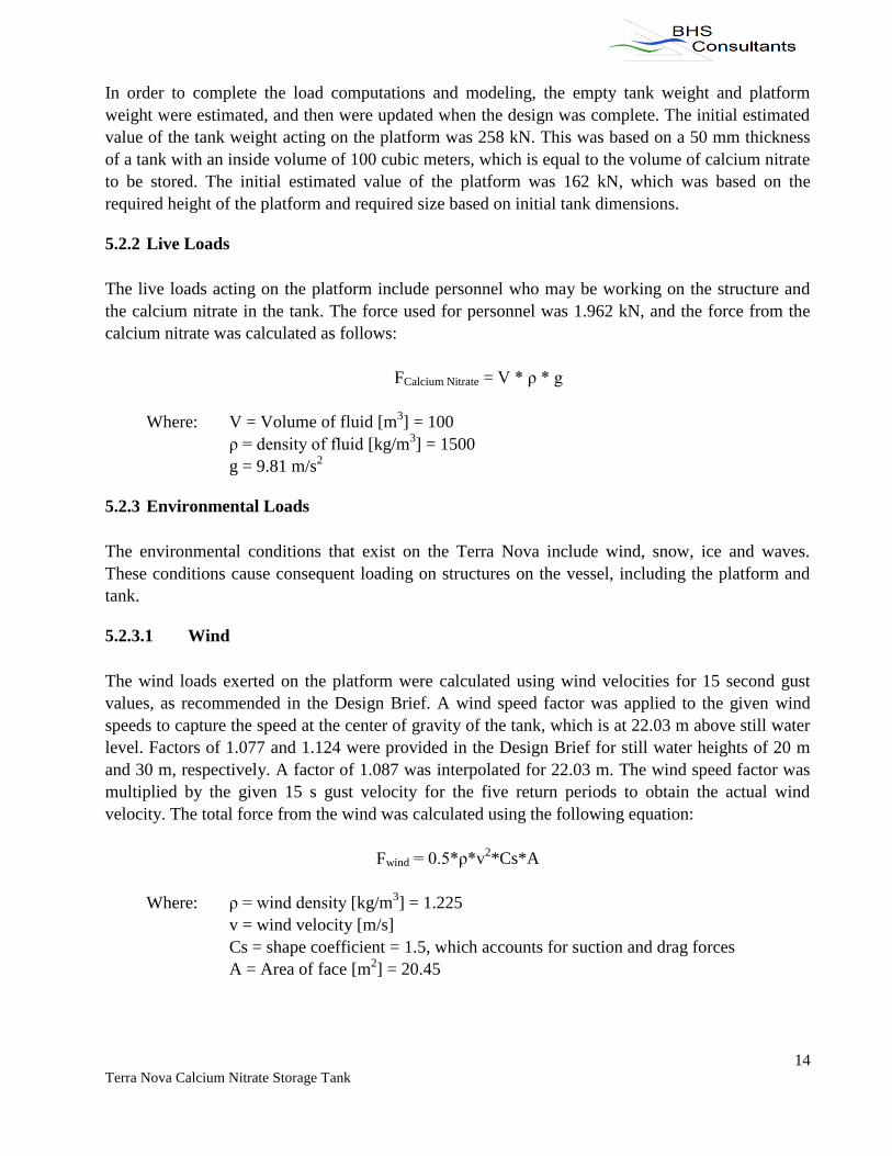
Table 5.5: Load combinations ............................................................................................................ 19
Table 5.6: Platform sections and utilizations ..................................................................................... 21
Table 6.1: Maximum forces and moments on the platform as obtained from the S-Frame model ... 24
Table 8.1: Minimum Working Load Limits for slings, shackles and master link for the tank lifting
system and component selection ........................................................................................................ 32
Table 8.2: Padeye design dimensions for tank lifting system ............................................................ 35
Table 8.3: Minimum Working Load Limits for slings, shackles and master link for the platform
lifting system and component selection ............................................................................................. 36
Table 8.4: Sling lengths for platform lifting system .......................................................................... 37
Table 8.5: Padeye design dimensions for tank lifting system ............................................................ 38
Table 9.1: Tank cost breakdown ........................................................................................................ 39
Table 9.2: Platform cost breakdown .................................................................................................. 39

Terra Nova Calcium Nitrate Storage Tank iii
List of Figures
Figure 1.1 Terra Nova FPSO Deck Drawing ....................................................................................... 1
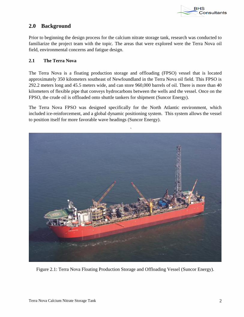
Figure 2.1: Terra Nova Floating Production Storage and Offloading Vessel (Suncor Energy). ......... 2
Figure 4.1: Hydrostatic pressure distribution along walls and bottom of tank .................................... 7
Figure 4.2: Pressure distribution along different surfaces of the tank caused by vessel acceleration
on the calcium nitrate fluid .................................................................................................................. 8
Figure 4.3: Outside view of tank from Abaqus .................................................................................... 9
Figure 4.4: Bulkheads inside tank from Abaqus ................................................................................ 10
Figure 4.5: Outside view of tank and stiffeners from Abaqus model ................................................ 10
Figure 4.6: Stress distribution on final tank design from Abaqus ..................................................... 11
Figure 4.7: Autocad Drawing of the Tank (See next page) ............................................................... 11
Figure 5.1: Platform model in S-Frame ............................................................................................. 20
Figure 5.2: Tank load representation on platform ............................................................................. 21
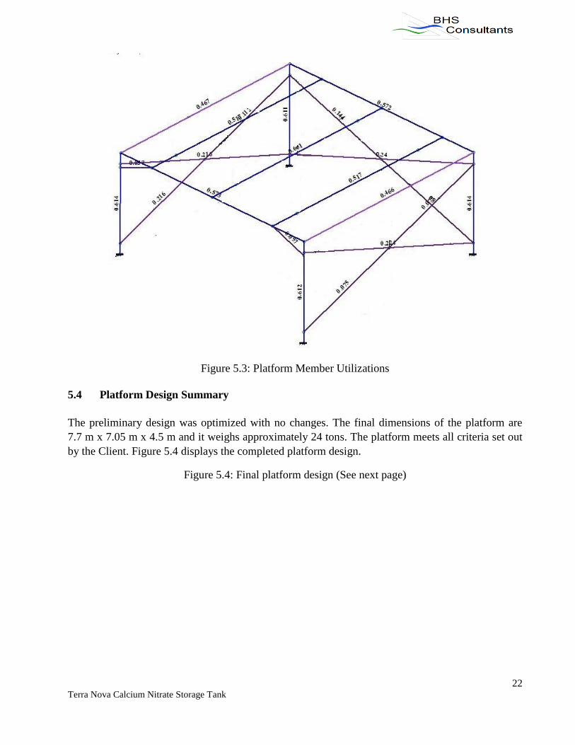
Figure 5.3: Platform Member Utilizations ......................................................................................... 22
Figure 5.4: Final platform design (See next page) ............................................................................. 22
Figure 6.1: Diagram of column and base plate showing bolt reactions ............................................. 26
Figure 6.2: Primary steel beam as bolted to secure the platform ....................................................... 28
Figure 6.3: Bolt locations in the base plate ........................................................................................ 29
Figure 7.1: Tank and platform seafastening design ........................................................................... 30
Figure 8.1: Typical four-point wire sling lifting assembly (Det Norske Veritas 39) ........................ 31
Figure 8.2: Padeye dimension diagram .............................................................................................. 35
Figure 8.3: Platform diagram showing liftpoints, center of gravity and geometric center ................ 36

Terra Nova Calcium Nitrate Storage Tank 1
1.0 Project Description
This project involved the design of a storage tank to hold and dispense aqueous calcium nitrate
solution from the Terra Nova FPSO. The tank must store 100 cubic meters of fluid, and must be
located at Module Four (MO4), starboard, which is approximately in the middle of the vessel. A
drawing of MO4 on the Terra Nova deck is displayed in Figure 1.1, as taken from the Terra Nova
Alliance Topsides Structural Design Brief (Design Brief). The tank must be equipped with a ladder
and nozzles for maintenance and use. Due to the location of the tank, a platform is required to hold
the tank approximately 4.5 meters above the deck surface to clear existing equipment. The platform
must be equipped with two exit ladders and railings and walkways around the tank for maintenance.
The equipment under the platform will affect the position of structural columns and bracing.
Figure 1.1 Terra Nova FPSO Deck Drawing
Terra Nova Calcium Nitrate Storage Tank 2
2.0 Background
Prior to beginning the design process for the calcium nitrate storage tank, research was conducted to
familiarize the project team with the topic. The areas that were explored were the Terra Nova oil
field, environmental concerns and fatigue design.
2.1 The Terra Nova
The Terra Nova is a floating production storage and offloading (FPSO) vessel that is located
approximately 350 kilometers southeast of Newfoundland in the Terra Nova oil field. This FPSO is
292.2 meters long and 45.5 meters wide, and can store 960,000 barrels of oil. There is more than 40
kilometers of flexible pipe that conveys hydrocarbons between the wells and the vessel. Once on the
FPSO, the crude oil is offloaded onto shuttle tankers for shipment (Suncor Energy).
The Terra Nova FPSO was designed specifically for the North Atlantic environment, which
included ice-reinforcement, and a global dynamic positioning system. This system allows the vessel
to position itself for more favorable wave headings (Suncor Energy).
`
Figure 2.1: Terra Nova Floating Production Storage and Offloading Vessel (Suncor Energy).
Terra Nova Calcium Nitrate Storage Tank 3
In 2010 hydrogen sulfide gas was detected in the Terra Nova field, slowing production. Hydrogen
sulfide is a flammable gas that occurs due to the decay of substances containing protein resulting
from bacterial reduction of sulfates in rocks. It can result when water is injected into a reservoir due
to microbial populations mixing with nutrients. Hydrogen sulfide is dangerous due to its toxicity
upon contact and flammability. This chemical is also extremely corrosive to all equipment,
including safety equipment, and can cause “sulfide stress cracking” and failure (Pinheiro).
Solutions for hydrogen sulfide presence in oil fields include biocide treatment or microbiological
competition. After consideration, the solution proposed for the Terra Nova field was the injection of
calcium nitrate into the field. This process encourages nitrate reduction thereby reducing sulfate
reduction (Statoil).
2.2 Environmental Concern
As part of the duty of an engineer, environmental concern with regards to design and practice is of
the utmost importance to BHS Consultants. Keeping with this, BHS Consultants is energy and waste
efficient with respect to our day to day activities, and our engineering practice. For the calcium
nitrate storage tank and platform design, BHS Consultants has completed the design using methods
and materials that we believe are sustainable and economical. Research was completed when
choosing structural materials in order to minimize resources and maximize economics and
sustainability.
2.3 Fatigue
Fatigue is mechanical failure that is caused by the repeated loading of time varying stresses on the
structure, or cyclic loading. For offshore structures, National Standard of Canada ISO 19902-09
(ISO 19902) states that this action is predominantly caused by waves hitting the structure. ISO
19902 also describes the importance of stress range (S) and the number of cycles (N) relating to
fatigue. The storage tank and supporting platform were designed for a minimum wave return period
of one year. Over the twenty year design life, that would cause approximately twenty cycles. In ISO
19902, cycles for fatigue design are of the order of 105 or greater, which is significantly higher than
the expected number of cycles for the structures. Furthermore, the load combination factors
decrease the stress range, which in turn lessons the effects of fatigue. Therefore, fatigue failure of
the storage tank and platform will not be considered as part of the module design (ISO 19902).
Terra Nova Calcium Nitrate Storage Tank 4
3.0 Methodology
The purpose of this project was to create an efficient, safe and economical design for a tank capable
of storing 100 cubic meters of calcium nitrate solution, and a platform that can support the tank.
Both will be installed offshore on the deck of the Terra Nova FPSO.
The design had to take into account a number of constraints. It had to accommodate a number of
vessel deck obstructions, which affected the height of the platform and position of the columns and
bracings of the platform. It also had to consider challenging offshore loading conditions. The
corrosive nature of calcium nitrate influenced tank material selection. Furthermore, safety
considerations, such as multiple exits routes from the platform, played a role in the design.
Preliminary designs were completed in order to begin load calculations. These designs were based
on the required inside volume of the storage tank, and support required of the platform. These
preliminary designs were used to compute dead load forces of the two structures. Next, the load
calculations were completed for both the tank and the platform. Individual load cases considered
dead loads, live loads, environmental loads and blast loads. These individual load cases were
factored and combined to generate a number of load combinations that were to be used for
modeling. The tank and the platform were modeled in S-Frame and Abaqus, respectively, and the
loads were applied. Then, the models were used to optimize the size of the structures and obtain a
final design.
After the structures were fully designed, seafasting and lifting designs were completed for the
transportation onto the Terra Nova deck. As hot work on the operating Terra Nova FPSO was
unacceptable, the structures would have to be bolted in place. These connections were completed
using the Handbook of Steel Construction.
Finally, a cost estimate was completed for the construction of the two structures. This estimate was
done using RS Means and research.

Terra Nova Calcium Nitrate Storage Tank 5
4.0 Tank Design
The storage tank is required to hold 100 cubic meters of calcium nitrate and will be refilled
approximately every two weeks. The tank will be constructed of stainless steel, and will be designed
in accordance with ISO 19902. A ladder will be provided to reach the top of the tank for calcium
nitrate loading and maintenance purposes. The loading events on the tank were computed based on
the requirements set out in the standards, and are described in detail in section 4.3. The tank was
modeled using Abaqus Finite Element Analysis. The lifting, seafastening and bolted connection
designs were completed in accordance with DNV Standard for Certification, No. 2.7-1, Offshore
Containers and the Steel Code, CSA-S16.
4.1 Material Selection
Various materials were investigated for the storage tank. This tank is required to be resistant to
corrosion. First, exotic steels were ruled out due to cost and availability. Next, carbon steel was
investigated. It was found that it would need corrosion protection inside the tank. Through contact
with Construction System Supply, it was found that the life of a corrosion liner is seven years. From
this information it was concluded that carbon steel with the corrosion liner would not be feasible for
the tank for two main reasons. First, the design life of the tank is to be twenty years, and therefore
would require shut downs in order to reapply the corrosion coating, and second, the combined cost
of the carbon steel material and the corrosion liner would be greater than that of stainless steel. It
was concluded that 316L stainless steel would be used for the tank.
4.2 Preliminary Design
In the preliminary stages of the tank design two options were considered, keeping in mind the
minimization of overall load effects. One option was a vertical cylindrical tank, and the second was
a rectangular tank.
Considering the design criteria, various conclusions were drawn with respect to the two frame
shapes. First, a rectangular frame creates a more manageable design process with regards to load
calculations and load application during the modeling stage. The connection of the tank to the
platform and maintenance of the tank during its lifetime would be simpler for a rectangular tank. It
was also considered that fabrication of a circular tank with stiffeners and interior bulkheads could
pose more difficulty than that of a rectangular tank, potentially adding cost. Considering these
conclusions, a rectangular frame was chosen to proceed in the design phase.
The preliminary design of the stainless steel rectangular tank was chosen to have inside dimensions
of 5 m long, by 5 m wide, by 4 m high. The wall thickness was set at 50 mm. The overestimation of
wall thickness was justified because the stiffeners and bulkheads were not considered and it was
deemed conservative to overdesign and then use the models to optimize. The tank has rectangular
stiffeners that extend around the tank in all directions to reinforce the tank and to minimize wall
thickness requirements. The size and spacing of these stiffeners was set to 10 mm and 500 mm

Terra Nova Calcium Nitrate Storage Tank 6
respectively. Bulkheads were placed inside the tank, dividing the tank into four compartments to
reduce the effect of fluid sloshing.
4.3 Design Loads
The calcium nitrate storage tank was designed to resist the various loads that will act on it during its
operation. Waves acting on the Terra Nova cause an acceleration of the structures on board of the
vessel. For the tank this includes the stainless steel structure, as well as the calcium nitrate fluid
inside. The acceleration of the fluid will cause pressures on the inside walls of the tank. These, as
well as the hydrostatic fluid pressures are the most extreme loads that the tank will experience.
Environmental loads including wind, snow and ice, and live loads such as personnel will not be
considered in the load cases for the tank. The rationale for this is that the hydrostatic forces act out
from the inside of tank, meaning that the environmental and live loads would counter these forces.
Therefore the only forces modeled on the tank are:
hydrostatic force due to the calcium nitrate fluid,
vessel acceleration on the tank caused by the wave action,
vessel acceleration on the calcium nitrate fluid caused by the wave action, and
blast force
It is important to note that the self-weight of the tank does not have to be included as a force. The
density of the stainless steel tank is modeled, which accounts for the self-weight. The forces
discussed are factored based on their wave conditions. This is done because the modeling program,
Abaqus, uses individual factored load cases to make combinations of loads that will act
simultaneously. The factors that are used are the same as those used for the calculation of the
platform load combinations. A summary of the tank load cases can be seen in Table 4.1.
Table 4.1: Factored tank load cases
Load Cases Load Factor
Load (kN)
x (long.) y (trans.) z (heave)
Hydrostatic force due to fluid (kN)
Unfactored 0.0596 0.0596 0.0596
Wave 1 (10 yr) 1.5 0.0894 0.0894 0.0894
Wave 2 (100 yr) 1.1 0.0656 0.0656 0.0656
Wave 3 (1 yr all yr) 1.1 0.0656 0.0656 0.0656
Wave 4 (1 yr all yr) 1 0.0596 0.0596 0.0596
Wave 5 (1 yr all yr) 1 0.0596 0.0596 0.0596
Vessel acceleration on tank (kN)
Wave 1 (10 yr) 1.215 26.8066 38.6331 37.5818
Wave 2 (100 yr) 1.35 30.2231 49.6711 43.8893
Wave 3 (1 yr all yr) 1.35 11.8264 135.6100 90.4066
Wave 4 (1 yr all yr) 1 30.7488 144.2827 43.3636
Wave 5 (1 yr all yr) 1 16.2942 202.3637 90.4066

Terra Nova Calcium Nitrate Storage Tank 7
Vessel acceleration on fluid (Pressure, MPa)
Wave 1 (10 yr) 1.215 0.0094 0.0135 0.0132
Wave 2 (100 yr) 1.35 0.0118 0.0193 0.0171
Wave 3 (1 yr all yr) 1.35 0.0046 0.0528 0.0352
Wave 4 (1 yr all yr) 1 0.0089 0.0416 0.0125
Wave 5 (1 yr all yr) 1 0.0047 0.0583 0.0261
Blast Force (kN)
Blast in x direction 1431.68 0.00 0.00
Blast in y direction 0.00 1431.68 0.00
The pressure that the fluid exerts on the tank due to the force of gravity is the hydrostatic pressure.
This pressure on the side of tank increases proportionately with depth from zero at the fluid surface
to a maximum pressure at the tank bottom, as a result of the increased weight of the fluid. There is
also a constant hydrostatic pressure exerted on the bottom surface of the tank that is equal to this
maximum pressure. Figure 4.1 shows the pressure distributions. The maximum hydrostatic pressure
was calculated as follows:
Phydrostatic = gh
Where: Phydrostatic = hydrostatic pressure [MPa]
= density of the fluid [kg/m3] = 1500
g = force of gravity [m/s2] = 9.81
h = height of the fluid [m] = 4.05
Figure 4.1: Hydrostatic pressure distribution along walls and bottom of tank

Terra Nova Calcium Nitrate Storage Tank 8
Vessel accelerations cause directional forces on the tank. Each wave causes a vessel acceleration in
the x, y and z directions, therefore a force on the tank was calculated for each of these directions for
each wave as follows:
Ftank, vessel acceleration = avessel * mtank
Where: Ftank, vessel acceleration = force caused by vessel accelerations on the tank [kN]
avessel = vessel acceleration, which is wave and directional dependant [m/s2]
mtank = mass of tank [kg] = 26,281
There is a pressure caused by the vessel accelerations on the fluid. Each wave causes a vessel
acceleration in the x, y and z directions, which results in a pressure exerted by the fluid. As a wave
causes the fluid to accelerate toward a particular surface, several different pressure distributions are
generated. The pressure increases proportionately with distance from zero to a maximum at the
surface the fluid is accelerating toward. There is also a constant pressure exerted on the surface that
the fluid is accelerating toward. Figure 4.2 shows the pressure distributions. Both the distributed
pressure maximum and the constant pressure were calculated as:
Pfluid, vessel acceleration = * avessel * h
Where: Pfluid, vessel acceleration = pressure cause by the vessel accelerations on the tank [MPa]
= density of the fluid [kg/m3] = 1500
avessel = vessel acceleration, which is wave and directional dependant [m/s2]
h = height of the fluid, which is dependent on the direction of fluid acceleration
[m]
Figure 4.2: Pressure distribution along different surfaces of the tank caused by vessel acceleration
on the calcium nitrate fluid
Terra Nova Calcium Nitrate Storage Tank 9
Blast loading is also considered as a force on the tank. This is the load that is exerted on the tank in
the event of a blast or explosion. The force on the tank as a result of blast loading is calculated as
follows:
Fblast = Pblast * A
Where: Fblast = force caused by blast loading [kN] = 1431.68
Pblast = pressure caused by blast [kPa] = 70 (Hamdan, pg.1, 2006)
A = projected area [m2] = 20.45
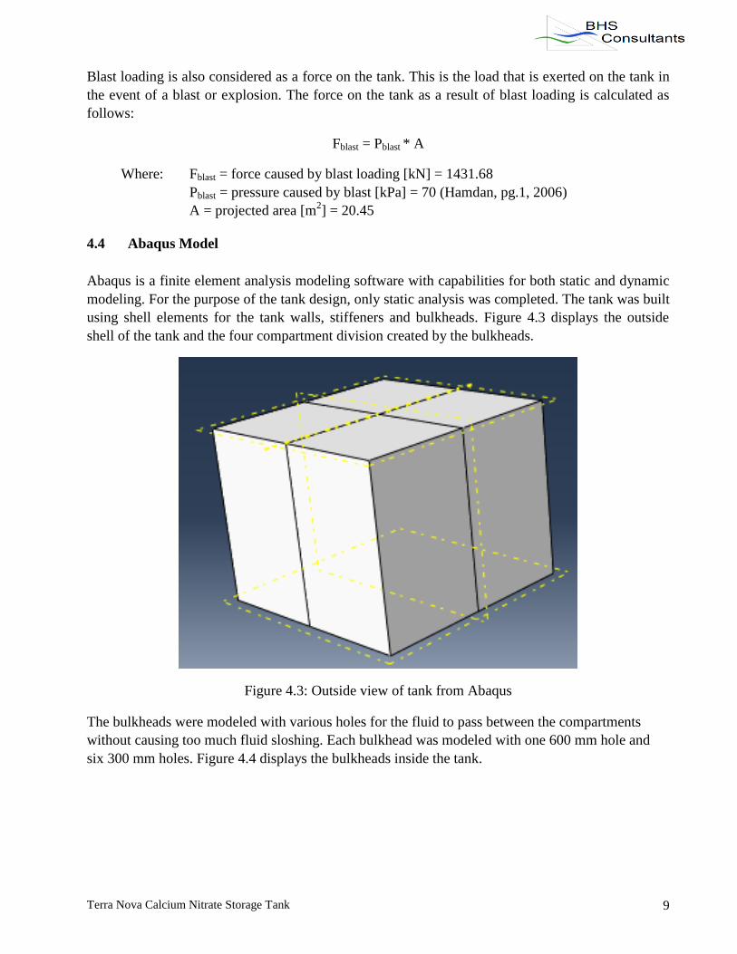
4.4 Abaqus Model
Abaqus is a finite element analysis modeling software with capabilities for both static and dynamic
modeling. For the purpose of the tank design, only static analysis was completed. The tank was built
using shell elements for the tank walls, stiffeners and bulkheads. Figure 4.3 displays the outside
shell of the tank and the four compartment division created by the bulkheads.
Figure 4.3: Outside view of tank from Abaqus
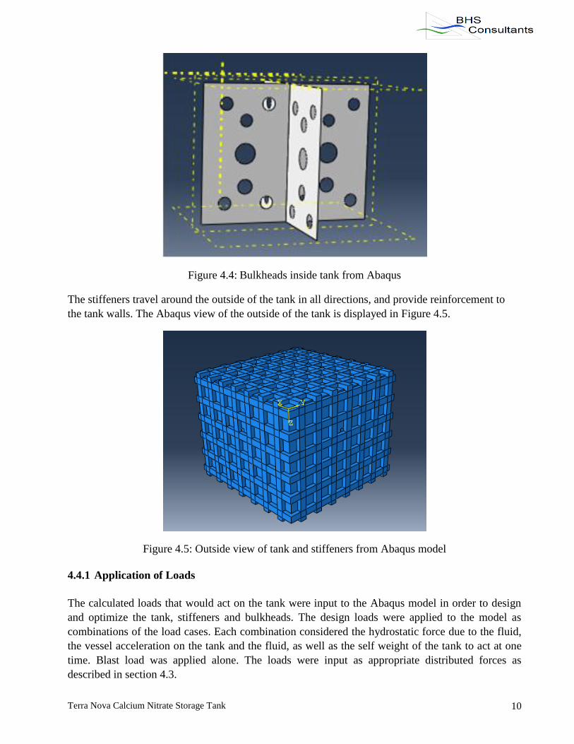
The bulkheads were modeled with various holes for the fluid to pass between the compartments
without causing too much fluid sloshing. Each bulkhead was modeled with one 600 mm hole and
six 300 mm holes. Figure 4.4 displays the bulkheads inside the tank.
Terra Nova Calcium Nitrate Storage Tank 10
Figure 4.4: Bulkheads inside tank from Abaqus
The stiffeners travel around the outside of the tank in all directions, and provide reinforcement to
the tank walls. The Abaqus view of the outside of the tank is displayed in Figure 4.5.
Figure 4.5: Outside view of tank and stiffeners from Abaqus model
4.4.1 Application of Loads
The calculated loads that would act on the tank were input to the Abaqus model in order to design
and optimize the tank, stiffeners and bulkheads. The design loads were applied to the model as
combinations of the load cases. Each combination considered the hydrostatic force due to the fluid,
the vessel acceleration on the tank and the fluid, as well as the self weight of the tank to act at one
time. Blast load was applied alone. The loads were input as appropriate distributed forces as
described in section 4.3.

Terra Nova Calcium Nitrate Storage Tank 11
4.4.2 Tank Optimization
After applying the loads it was concluded that the preliminary tank was overdesigned, and the wall
thickness could be reduced. Optimization of the tank was completed to create an economical and
functional design. By reducing the wall thickness and stiffener spacing and re-running the software,
the wall thickness was finalized at 8 mm. The stiffener thickness was 8 mm, and they were placed at
750 mm intervals in all directions around the tank. Figure 4.6 displays the stress distribution on the
final tank design. The colors signify the stress intensity throughout the tank, where dark blue is very
low stress, yellow/green is medium stress, and red shows the high stress areas. It is important to note
that these colors do not signify failure of the tank in any location. The mix of colors does display
that the tank is not completely over or under designed.
Figure 4.6: Stress distribution on final tank design from Abaqus
4.5 Tank Design Summary
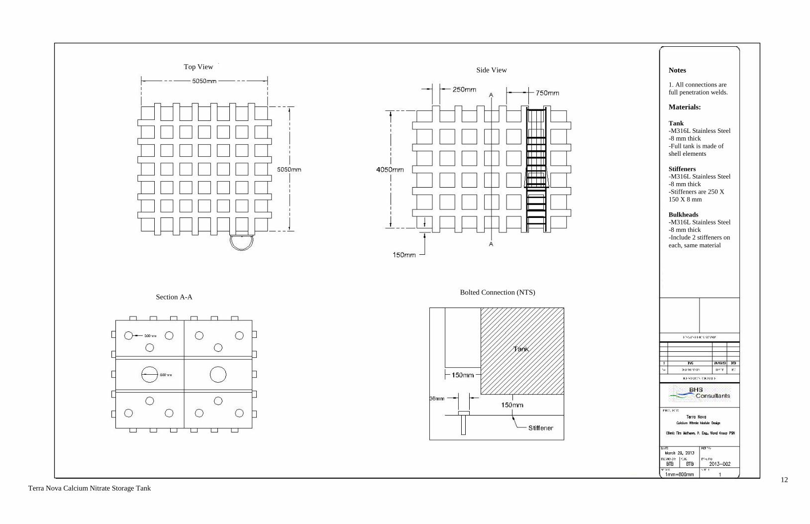
After completing the tank model in Abaqus, the final stainless steel tank design had dimensions as
displayed in Table 4.2. Figure 4.7 displays the drawing that was completed for the tank design.
Table 4.2: Tank dimensions
Parameter Measurement
Inside Width/Length 5000 mm
Inside Height 4000 mm
Wall Thickness 8.0 mm
Stiffener Thickness 8.0 mm
Stiffener Spacing 750 mm
Bulkhead Hole Diameter 1 – 600 mm, 6 – 300 mm
Total Weight 17, 139 kg
Figure 4.7: AutoCAD Drawing of the Tank (See next page)
12
Terra Nova Calcium Nitrate Storage Tank
Top View Side View
Section A-A Bolted Connection (NTS)
Notes
1. All connections are
full penetration welds.
Materials:
Tank
-M316L Stainless Steel
-8 mm thick
-Full tank is made of
shell elements
Stiffeners
-M316L Stainless Steel
-8 mm thick
-Stiffeners are 250 X
150 X 8 mm
Bulkheads -M316L Stainless Steel
-8 mm thick
-Include 2 stiffeners on
each, same material
13 Terra Nova Calcium Nitrate Storage Tank
5.0 Platform Design
The platform will be constructed of steel with a yield strength of 350 MPa and it is required to hold
the storage tank filled with 100 cubic meters of calcium nitrate solution. It will be located on MO4,
which is a fully operating section of the Terra Nova FPSO. Therefore it was necessary for the
platform to be designed around the existing topside infrastructure. The platform will be erected on
MO4, starboard, which has multiple restrictions to overcome. The platform needed to be at least 4.5
m high. Therefore, there were only four appropriate positions for the columns and the stern side of
the platform could not be fully braced due to underlying pipes.
The platform was designed in accordance with ISO 19902, and also the Steel Code, CSA-S16. The
platform will be equipped with a walkway and railing, as well as two exits with ladders, to allow
access for maintenance. The design process began with a preliminary outline.
5.1 Preliminary Design
The preliminary design of the platform was rectangular, with dimensions of 7.7 m (starboard-port) x
7.05 m (bow-stern) . At each corner there is a square hollow column extending 4.5 m in height. The
columns will be connected together by W sections at the top inside faces and square hollow cross
bracing connected 0.5 m and 3.85 m above the deck. However, the connections at the side closest to
the stern will be connected by W sections at the top inside faces and corner bracing at 3.85 m above
the deck due to the aforementioned restrictions. The platform will also be equipped with a steel
mesh deck, two ladders on the stern side and hand railing around the full perimeter of the topside.
5.2 Design Loads
The platform is designed to resist the various loads that could potentially act on the structure during
its design life. The loading calculations were done in accordance with ISO 19902. The platform was
designed to resist dead loads, such as self weight, and the weight of the tank; live loads, such as
personnel and the calcium nitrate; environmental loads, such as wind, ice, snow and waves; and
blast loads.
5.2.1 Dead Loads
The dead loads acting on the platform include the weight of the tank and the platform self weight.
The weight of both the empty tank and the platform were calculated as:
FDL = Vsteel * ρ * g
Where: Vsteel = Volume of steel in the tank [m3] = 2.15
ρ = density of steel [kg/m3] = 8000 for stainless steel, and 7850 for steel
g = 9.81 m/s2
14 Terra Nova Calcium Nitrate Storage Tank
In order to complete the load computations and modeling, the empty tank weight and platform
weight were estimated, and then were updated when the design was complete. The initial estimated
value of the tank weight acting on the platform was 258 kN. This was based on a 50 mm thickness
of a tank with an inside volume of 100 cubic meters, which is equal to the volume of calcium nitrate
to be stored. The initial estimated value of the platform was 162 kN, which was based on the
required height of the platform and required size based on initial tank dimensions.
5.2.2 Live Loads
The live loads acting on the platform include personnel who may be working on the structure and
the calcium nitrate in the tank. The force used for personnel was 1.962 kN, and the force from the
calcium nitrate was calculated as follows:
FCalcium Nitrate = V * ρ * g
Where: V = Volume of fluid [m3] = 100
ρ = density of fluid [kg/m3] = 1500
g = 9.81 m/s2
5.2.3 Environmental Loads
The environmental conditions that exist on the Terra Nova include wind, snow, ice and waves.
These conditions cause consequent loading on structures on the vessel, including the platform and
tank.
5.2.3.1 Wind
The wind loads exerted on the platform were calculated using wind velocities for 15 second gust
values, as recommended in the Design Brief. A wind speed factor was applied to the given wind
speeds to capture the speed at the center of gravity of the tank, which is at 22.03 m above still water
level. Factors of 1.077 and 1.124 were provided in the Design Brief for still water heights of 20 m
and 30 m, respectively. A factor of 1.087 was interpolated for 22.03 m. The wind speed factor was
multiplied by the given 15 s gust velocity for the five return periods to obtain the actual wind
velocity. The total force from the wind was calculated using the following equation:
Fwind = 0.5*ρ*v2*Cs*A
Where: ρ = wind density [kg/m3] = 1.225
v = wind velocity [m/s]
Cs = shape coefficient = 1.5, which accounts for suction and drag forces
A = Area of face [m2] = 20.45

15 Terra Nova Calcium Nitrate Storage Tank
Table 5.1 displays the results of this calculation for the various return periods. The total wind force
was broken into x and y components. It was assumed that the headwind acted at 20 degrees to the
bow of the vessel because the Terra Nova spins to optimize conditions.
Table 5.1: Wind loads components
Fwind (kN)
Total x component y component
1 yr ice 17.39 7.10 15.88
1 yr all yr 29.72 12.13 27.13
10 yr 35.85 14.63 32.73
50 yr 50.47 20.60 46.08
100 yr 57.25 23.36 52.26
5.2.3.2 Ice
The forces that result from ice accumulation were calculated for the tank and for the platform, as
they will both contribute to the load on the platform. The Design Brief describes the effects of sea
spray icing, but because the height of the tank is greater than 25 meters above water level, the effect
of sea spray will not be considered. It is important to note that an additional volume of ice would
accumulate at the corners of the tank and this is accounted for in the force calculation. The force due
to ice accumulation on the platform and the tank was calculated using the following formula:
Fice = ρ * t * A * g
Where: ρ = density of ice [kg/m3] = 900
t = thickness of ice [m] = 0.01
A = surface area of tank or platform [m2] = 132.815 or 24.2, respectively
Therefore, the total force due to ice acting on both the tank and the platform are as follows:
Fice tank = 11.762 kN
Fice platform = 2.137 kN
5.2.3.3 Snow
The force on the platform and tank due to snow accumulation was calculated using the pressure of
snow given in the Design Brief, section 3.3.6. This force was calculated as follows:
Fsnow = P * A
Where: P = pressure of snow from the Design Brief [kg/m2]= 204
A = top surface area of tank or platform [m2] = 25.50 or 24.2, respectively

16 Terra Nova Calcium Nitrate Storage Tank
Therefore, the total force on the tank and platform due to snow are:
Fsnow tank = 51.037 kN
Fsnow platform = 48.43 kN
5.2.3.4 Waves
Sea conditions involving waves cause different accelerations of the Terra Nova, hereafter referred to
as vessel accelerations. These accelerations are given in Table 5.2.
Table 5.2: Consequent vessel accelerations due to wave conditions
Design Condition Sea State Unit Function
Max single amplitude acceleration
x, long y, trans z, vert
m/s2 m/s
2 m/s
2
1, Operating 10 bow year Running 1.02 1.47 11.24
2, Survival Bow 100 bow year Stopped 1.15 1.89 11.48
3, Survival Beam 1 year beam Stopped 0.45 5.16 13.25
4, Vessel Damaged 1 year oblique Stopped 1.17 5.49 11.46
5, Vessel Damaged 1 year beam Stopped 0.62 7.7 13.25
The vessel accelerations cause accelerations and subsequent forces on the platform, tank and
calcium nitrate fluid in the x, y and z direction. Roll forces are caused in the x or longitudinal
direction; pitch forces are caused in the y or transverse direction; and heave forces are caused in the
z or vertical direction. The equation used to convert the vessel accelerations into forces on the
platform, tank and fluid is as follows:
Fwave = m * a
Where: m = mass of the tank, fluid or platform [kg]
a = given vessel acceleration [m/s2], as seen in Table 5.2
Table 5.3 displays the resulting forces that were considered to act on the tank, platform and fluid as
a result of the vessel accelerations.

17 Terra Nova Calcium Nitrate Storage Tank
Table 5.3: Forces on the platform, tank and fluid resulting from the vessel accelerations
Design condition Sea state Forces on tank
[kN]
Forces on platform
[kN]
Forces on fluid
[kN]
x y z x y z x y z
Operating 10 bow year 27 39 38 17 24 24 153 221 215
Survival Bow 100 bow year 30 50 44 19 31 28 173 284 251
Survival Beam 1 year beam 12 136 90 7 85 57 68 774 516
Vessel Damaged 1 year oblique 31 144 43 19 91 27 176 824 248
Vessel Damaged 1 year beam 16 202 90 10 127 57 93 1155 516
5.2.3.5 Blast Loading
Blast loading on a vessel includes explosions caused by hydrocarbon fires and acts of violence. ISO
19902, section 10.4 states that generally steel framed structures on vessels are not designed against
explosion. However, on request of the Client, a blast pressure of 0.7 bar was modeled on all sides of
the tank. The resulting force from a blast was found as follows:
Fblast = A * Pblast
Where: A = projected area of tank [m2] = 24.4525
Pblast = pressure of the design blast [kPa] = 70 (Hamdan 1)
This calculation resulted in a blast force of 1431.675 kN in both the x and y directions, on the side
of the tank.
5.2.4 Load Combinations
The calculation of the individual dead loads, live loads, environmental loads and blast loads are
referred to as load cases. These load cases are combined to create a number of load combinations
that consider appropriate cases to be acting simultaneously. Therefore, each load combination has a
single x, y and z force component. Load combination factors specific to the individual load cases
were found in ISO 19902, section 9, and were applied to the load case forces when they were added
together to calculate the load combination forces. The combination factors for the different cases are
based on the specific conditions under which loading occurred. This depends on whether the vessel
was in operating, survival, damaged or still water mode, the return rate of the wave, and where the
force was acting. Table 5.4 is a summary of the combination factors that were used.

18 Terra Nova Calcium Nitrate Storage Tank
Table 5.4: Load combination factors
Load Combination Factors
DL LL Wave Wind Snow Ice
Wave 1 Compression 1.3 1.5 1.215 1.215 1.215 1.215
Uplift 1.1 1.1 1.215 1.215 0 0
Wave 2 Compression 1.1 1.1 1.35 1.35 1.35 1.35
Uplift 0.9 0.8 1.35 1.35 0 0
Wave 3 Compression 1.1 1.1 1.35 1.35 1.35 1.35
Uplift 0.9 0.8 1.35 1.35 0 0
Wave 4 Compression 1 1 1 1 1 1
Uplift 1 1 1 1 0 0
Wave 5 Compression 1 1 1 1 1 1
Uplift 1 1 1 1 0 0
Still 1.3 1.5 0 1.35 1.5 1.5
Blast 1 1 1 1 1 1
For each of the five waves there were four compression and four uplift load combinations.
Compression combinations accounted for the maximum downward force, and therefore considered a
full tank, the platform, all live loads, and wave, wind, snow and ice forces. The heave force, which
is the vertical wave component, was considered to be working downward in a negative direction.
Conversely, uplift combinations accounted for the maximum upward force, and considered only an
empty tank, the platform, wave and wind forces. In this case, the heave force was considered to be
working upwards in a positive direction. All other forces were not considered as they act downward
and would minimize uplift. To maximize the x and y components of the force for each load
combination, wave and wind loads were always assumed to act in the same direction when they
were both present. Still water combinations and blast loading combinations were also considered. It
is important to note that the wind return period used in each combination was equal to that of the
wave return period. In total, there are forty load combinations for the different waves, five for still
water and two for blasting. The total load acting on the platform for each combination was
calculated by adding the appropriate load cases in the x, y, and z directions. Table 5.5 displays all
forty-seven load combinations that were modeled on the platform in order to design the structure.
19 Terra Nova Calcium Nitrate Storage Tank
Table 5.5: Load combinations Load Type Load Case Fx [kN] Fy [kN] Fz [kN]
Wave 1,
Operating,
10 Year Bow
Max Compression 1 1001 257 384 -3324
Max Compression 2 1002 257 -384 -3324
Max Compression 3 1003 -257 384 -3324
Max Compression 4 1004 -257 -384 -3324
Max Uplift 1 1005 71 76 -468
Max Uplift 2 1006 71 -76 -468
Max Uplift 3 1007 -71 76 -468
Max Uplift 4 1008 -71 -76 -468
Wave 2,
Survival Bow,
100 Year Bow
Max Compression 1 2001 331 562 -2751
Max Compression 2 2002 331 -562 -2751
Max Compression 3 2003 -331 562 -2751
Max Compression 4 2004 -331 -562 -2751
Max Uplift 1 2005 98 180 -347
Max Uplift 2 2006 98 -180 -347
Max Uplift 3 2007 -98 180 -347
Max Uplift 4 2008 -98 -180 -347
Wave 3, Survival
Beam,
1 Year Bow
Max Compression 1 3001 129 1,370 -3212
Max Compression 2 3002 129 -1,370 -3212
Max Compression 3 3003 -129 1,370 -3212
Max Compression 4 3004 -129 -1,370 -3212
Max Uplift 1 3005 38 325 -245
Max Uplift 2 3006 38 -325 -245
Max Uplift 3 3007 -38 325 -245
Max Uplift 4 3008 -38 -325 -245
Wave 4, Vessel
Damaged,
1 Year Oblique
Max Compression 1 4001 238 1,085 -2398
Max Compression 2 4002 238 -1,085 -2398
Max Compression 3 4003 -238 1,085 -2398
Max Compression 4 4004 -238 -1,085 -2398
Max Uplift 1 4005 62 235 -423
Max Uplift 2 4006 62 -235 -423
Max Uplift 3 4007 -62 235 -423
Max Uplift 4 4008 -62 -235 -423
Wave 5, Vessel
Damaged, 1 Year
Beam
Max Compression 1 5001 132 1,512 -2743
Max Compression 2 5002 132 -1,512 -2743
Max Compression 3 5003 -132 1,512 -2743
Max Compression 4 5004 -132 -1,512 -2743
Max Uplift 1 5005 39 329 -346
Max Uplift 2 5006 39 -329 -346
Max Uplift 3 5007 -39 329 -346
Max Uplift 4 5008 -39 -329 -346
Still Water
Still Water 1 6001 9.58 21.43 -3021
Still Water 2 6002 16.37 36.62 -3021
Still Water 3 6003 19.75 44.18 -3021
Still Water 4 6004 27.81 62.21 -3021
Still Water 5 6005 31.54 70.55 -3021
Blast
Blast Loading 1 7001 1431.675 0 -1967
Blast Loading 2 7002 0 1431.675 -1967
20 Terra Nova Calcium Nitrate Storage Tank
5.3 S-Frame Model
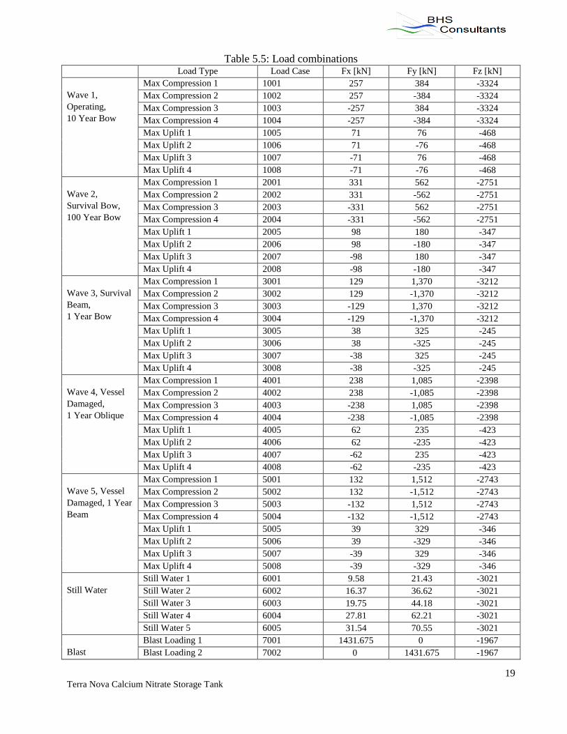
S-Frame and S-Steel were chosen as the computer software to model and optimize the preliminary
design of the platform. The primary steel of MO4 was included in the modeled version of the
platform to ensure that the loads caused from the platform and the tank did not cause the primary
steel to fail. Figure 5.1 displays the platform in S-Frame.
Figure 5.1: Platform model in S-Frame
5.3.1 Application of Loads
The platform had to be analyzed for the environmental, dead and live loads acting on the members,
which were direct loads, as well as the loads created by and acting on the calcium nitrate tank,
which were indirect loads.
For the direct loads, the platform was analyzed by applying uniform distributed loads (UDL) on
each cross bracing, corner bracing, column and on the top deck. The UDLs consisted of horizontal
wind forces and vertical snow and ice forces.
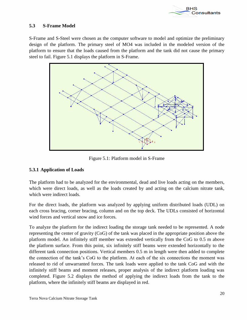
To analyze the platform for the indirect loading the storage tank needed to be represented. A node
representing the center of gravity (CoG) of the tank was placed in the appropriate position above the
platform model. An infinitely stiff member was extended vertically from the CoG to 0.5 m above
the platform surface. From this point, six infinitely stiff beams were extended horizontally to the
different tank connection positions. Vertical members 0.5 m in length were then added to complete
the connection of the tank’s CoG to the platform. At each of the six connections the moment was
released to rid of unwarranted forces. The tank loads were applied to the tank CoG and with the
infinitely stiff beams and moment releases, proper analysis of the indirect platform loading was
completed. Figure 5.2 displays the method of applying the indirect loads from the tank to the
platform, where the infinitely stiff beams are displayed in red.
21 Terra Nova Calcium Nitrate Storage Tank
Figure 5.2: Tank load representation on platform
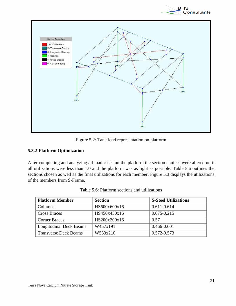
5.3.2 Platform Optimization
After completing and analyzing all load cases on the platform the section choices were altered until
all utilizations were less than 1.0 and the platform was as light as possible. Table 5.6 outlines the
sections chosen as well as the final utilizations for each member. Figure 5.3 displays the utilizations
of the members from S-Frame.
Table 5.6: Platform sections and utilizations
Platform Member Section S-Steel Utilizations
Columns HS600x600x16 0.611-0.614
Cross Braces HS450x450x16 0.075-0.215
Corner Braces HS200x200x16 0.57
Longitudinal Deck Beams W457x191 0.466-0.601
Transverse Deck Beams W533x210 0.572-0.573
22 Terra Nova Calcium Nitrate Storage Tank
Figure 5.3: Platform Member Utilizations
5.4 Platform Design Summary
The preliminary design was optimized with no changes. The final dimensions of the platform are
7.7 m x 7.05 m x 4.5 m and it weighs approximately 24 tons. The platform meets all criteria set out
by the Client. Figure 5.4 displays the completed platform design.
Figure 5.4: Final platform design (See next page)

22 Terra Nova Calcium Nitrate Storage Tank
23 Terra Nova Calcium Nitrate Storage Tank
6.0 Bolted Connections
Bolted connections must be designed to connect the tank to the platform, and the platform to the
primary steel that exists under the deck on the vessel. The following subsections complete the
design of these connections, as well as check the structural integrity of the primary steel beams.
High strength A325 bolts are to be used since A490 bolts often fail in fatigue. The design of bolted
connections follows the Handbook of Steel Construction, 10th
Edition by the Canadian Institute of
Steel Construction (CISC). All clauses referred to throughout this section are from this handbook.
6.1 Tank to Platform
The tank is to be bolted at six locations through the stiffeners to the platform deck. The maximum
shear at the platform connections was determined to be 395 kN from the S-Frame model. The shear
resistance is calculated according to clause 13.12.1.2.c of the handbook to ensure it is greater than
the applied shear force.
Vr = 0.60ΦbnmAbFu
Where: Vr = shear capacity [kN] = 405.57
Φb = 0.8
n = number of bolts = 1
m = number of shear planes = 1
Ab = area of bolt [mm2] = 1018
Fu = specified minimum tensile strength [MPa] = 830
Using only one M36 high strength A325 bolt for each of the six connections, the shear capacity is
405.57 kN, which is greater than the maximum applied shear force of 395 kN.
The maximum uplift (tension force) experienced is compared to the calculated tensile resistance to
determine whether the selected bolt type is sufficient. According to clause 12.12.1.3 of the
handbook, the tensile resistance is:
Tr = 0.75ΦbAbFu
Where: Tr = tension capacity [kN] = 506.96
Φb = 0.8
Ab = area of bolt [mm2] = 1018
Fu = specified minimum tensile strength [MPa] = 830
The calculated tensile resistance of 506.96 kN is far greater than the maximum tension force of 53
kN, so the selected bolt design is acceptable.
The tank will be bolted to the platform deck through the stiffeners using one M36 high strength
A325 bolt at each of the six connection locations.
24 Terra Nova Calcium Nitrate Storage Tank
6.2 Platform to Primary Steel
Bolted connections must be designed to connect the platform to the vessel deck at the four columns.
For the design of the column’s bolted connections, the maximum forces and moments are
determined from the S-Frame model. They are summarized in Table 6.1.
Table 6.1: Maximum forces and moments on the platform as obtained from the S-Frame model
Maximum Forces and Moments (S-Frame)
Largest x force [kN] 88.6
Largest y force [kN] 376.1
Largest z force, compression [kN] 135
Largest z force, tension [kN] 135
Largest Moment [kN m] 1203
6.2.1 Bearing, Shear and Tensile Resistance of Bolts
The bearing, shear and tensile resistances must be calculated and compared to the values from the
platform model. The bolt number and size, as well as the base plate dimensions, are selected based
on these resistance checks.
The bearing resistance is calculated according to clause 13.12.1.2.a of the handbook. To choose the
number of bolts and the plate thickness, the applied bearing force was set to be half that of the
applied shear force. Then a number of bolts were assumed to calculate the required plate thickness,
and a plate thickness was assumed to calculate the required number of bolts.
Br = 3ΦbrntdFu
Where: Br = bearing capacity [kN] = 193.2
Φbr = 0.8
n = number of bolts
t = thickness of plate [mm]
d = bolt diameter [mm] = 36
Fu = specified minimum tensile strength [MPa] = 450
Assuming n = 8, t = 1.11 mm
Assuming t = 10 mm, n = 0.89
An initial bolt diameter of 36 mm was assumed for the above calculations. Since the calculated
number of bolts and plate thickness were quite small, larger values were assumed. These values will
be decreased later if after all the checks show the resistances are much greater than the applied
forces. The M36 A325M bolts have a diameter of 36 mm, an area of 1018 mm2, and a specified
minimum tensile strength of 830 MPa. The bolt parameters were used to determine both shear and
tensile resistance.

25 Terra Nova Calcium Nitrate Storage Tank
The shear resistance was calculated according to clause 13.12.1.2.c of the handbook.
Vr = 0.60ΦbnmAbFu
Where: Vr = shear capacity [kN] = 3244.57
Φb = 0.8
n = number of bolts = 8
m = number of shear planes = 1
Ab = area of bolt [mm2] = 1018
Fu = specified minimum tensile strength [MPa] = 830
The shear capacity of 3244.57 kN was larger than the applied shear force of 386.4 kN. Therefore,
the selected number and size of bolts is sufficient.
The tensile resistance was calculated next. It was compared to the maximum tension in each bolt
which is calculated when checking the primary steel in section 6.2.2. According to clause 12.12.1.3
of the handbook, tensile resistance is determined.
Tr = 0.75ΦbAbFu
Where: Tr = tension capacity [kN] = 506.96
Φb = 0.8
Ab = area of bolt [mm2] = 1018
Fu = specified minimum tensile strength [MPa] = 830
6.2.2 Primary Steel Integrity
The platform and tank will be located on an operating section of the vessel. Therefore it was
required to determine if the existing structural members that will be supporting the designed tank
and platform would be able to handle the additional load. Both the web bearing and the flange
bending were checked for the compression and tension cases, respectively. The web bearing
resistance is the smaller of the two resistances calculated according to clause 14.3.2.a.
Br,1 = Φbw(N+10t)Fy
Br,2 = Φbiw2√(FyE)
Where: Br,1 = bearing capacity [kN] = 5600.00
Br,2 = bearing capacity [kN] = 3822.10
Φb, Φbi = 0.80
w = thickness of web [mm] = 20
N = length of plate [mm] = 700
t = thickness of flange [mm] = 30
Fy = specified minimum yield stress [MPa] = 350
E = modulus of elasticity [MPa] = 200,000

26 Terra Nova Calcium Nitrate Storage Tank
The applied bearing of 135 kN is far less than the bearing resistance of 3822.10 kN, therefore the
design is acceptable.
The flange bending is checked assuming a pattern of circular yielding for a pair of bolts separated
by a web in a flange. The effective length of the yielding zone was then calculated and used to
calculate the moment resistance of the flange.
Leff = 2m
z = Lefft2 / 4
Where: Leff = effective length [mm] = 439.82
m = distance from web edge to center of bolt hole [mm] = 70
z = [mm3] = 98,960
t = thickness of flange [mm] = 30
Mr = ΦzFy
Where: Mr = moment resistance calculated as [kN m] = 31.17
Φ = 0.9
Fy = specified minimum yield stress [MPa] = 350
Now the factored moment applied to the flange can be calculated to ensure it is less than the
moment resistance of the flange. Figure 6.1 shows the column and the base plate along with the
location of the bolt holes on the base plate. The reactions at the bolts that cause consequent reactions
on the flange of the primary steel beam are shown.
Figure 6.1: Diagram of column and base plate showing bolt reactions

27 Terra Nova Calcium Nitrate Storage Tank
The applied moment to the column is known and relates to the bolt reactions as follows.
Mapplied = 2Rbolt1dbolt1 + 2Rbolt2dbolt2
Where: Mapplied = applied moment to column [kN m] = 1203
Rbolt1 = reaction at bolt 1 [kN]
Rbolt2 = reaction at bolt 2 [kN]
Using ratios, Rbolt1 and Rbolt2 were calculated as 450.64 kN and 396.71 kN respectively.
The maximum tension force in a bolt must be determined next, which will be the bolt with the
largest reaction force. The tension force in the column, divided by the number of bolts, is added to
the bolt reaction force to find the maximum tension.
Tf = Tcolumn/n + Rbolt1
Where: Tf = maximum tension in bolt calculated as [kN] = 467.51
Tcolumn = largest z force (tension) applied to column [kN] = 135
n = number of bolts = 8
Returning briefly to the tensile resistance check in section 6.2.1, the tensile resistance of 567.72 kN
is larger than the applied tension force of 467.6 kN. The tension capacity is not much larger than the
applied tension force, so the bolted connections are not overdesigned and the choice of 8 M36 high
strength A325M bolts was reasonable.
It is also necessary to ensure that the bolts are acceptable under combined shear and tension
conditions. The check from Clause 13.12.1.3 must be satisfied. The values for shear resistance
(assuming threads intercepted to be conservative) and tensile resistance are from Table 3-4 of the
handbook.
(Vf/Vr)2 + (Tf/Tr)
2 = 0.88 < 1
Where: Vf = factored shear for one bolt [kN] = 48.30
Vr = shear resistance [kN] = 284
Tf = maximum tension in bolt [kN] = 467.51
Tr = tensile resistance [kN] = 507
Because the calculated value was found to be less than 1, this check is satisfied.
Finally, the factored moment applied to the flange can be calculated and compared to the moment
resistance. To do this, the required distance from the center of the web to the center of the bolt hole
must be found. The required diameter of a plain circular washer for a M36 bolt is 72 mm according
to a table on p. 6.64 of the handbook. Figure 6.2 shows the location of the bolt in relation to the web
of the primary steel. Here, the minimum distance is represented by emin and using the required weld
and washer size it was found to equal 60 mm.

28 Terra Nova Calcium Nitrate Storage Tank
Figure 6.2: Primary steel beam as bolted to secure the platform
The factored moment was calculated using the distance and the maximum tension in the bolt as
follows:
Mf = Tf * e
Where: Mf = factored moment calculated as [kNm] = 28.05
e = distance from web edge to center of bolt hole [mm] = 60
The factored moment of 28.05 kN m is less than the moment resistance of 31.17 kN m that was
found above, and the web bearing is sufficient. Therefore, the primary steel capacity is adequate to
support the designed platform, tank and connections.
6.2.3 Base Plate Bending
The bending of the base plate under the platform column must be checked to ensure it does not fail
due to applied loads. The base plate is only bolted to the primary steel in the plane of the primary
steel web. Therefore, the base plate in the direction perpendicular to the primary steel web is only
required to be sized to accommodate the full penetration weld between the platform column and the
plate. A size of 700 mm was selected.
In the direction of the primary steel beam web the base plate must be sized to accommodate the
bolts as well. A size of 1050 mm is chosen based on calculation of the minimum size required in
this direction, which is:
Lengthmin = Lengthcolumn + 2dweb edge to bolt1 + 2dbolt1 to bolt2 + 2(edge distance)
Where: Lengthmin = required length of base plate calculated as [mm] = 1048, use 1050
Lengthcolumn = length of column [mm] = 600
dweb edge to bolt1 = distance from web edge to center of bolt 1 [mm] = 70
dweb edge to bolt2 = center to center distance between bolt 1 and 2 [mm] = 90
edge distance [mm] = 64, required for M36 bolts according to clause 22.3.2, Table
6
29 Terra Nova Calcium Nitrate Storage Tank
The factored moment was then determined as follows:
Mf = (2Rbolt1dbolt1 + 2Rbolt2dbolt2)(dweb to bolt2)
Where: Mf = factored moment calculated as [kN m] = 194.89
Rbolt1 = reaction at bolt 1 [kN] = 450.64
dbolt1 = distance from far column edge to center of bolt 1 [mm] = 752
Rbolt2 = reaction at bolt 2 [kN] = 396.71
dbolt2 = distance from far column edge to center of bolt 2 [mm] = 662
dweb to bolt2 = distance from web edge to center of bolt hole 2 [mm] = 115
By setting the factored moment equal to the moment resistance, the following two equations were
used to solve for z, and then for the required pate thickness.
Mr = Mf = ΦzFy
Where: Φ = 0.9
z = [mm3] = 618,696.46
Fy = specified minimum yield stress [MPa] = 350
z = bt2 / 4
Where: b = length of plate [mm] = 700
t = thickness of plate, calculated as [mm] = 29.73, use 35
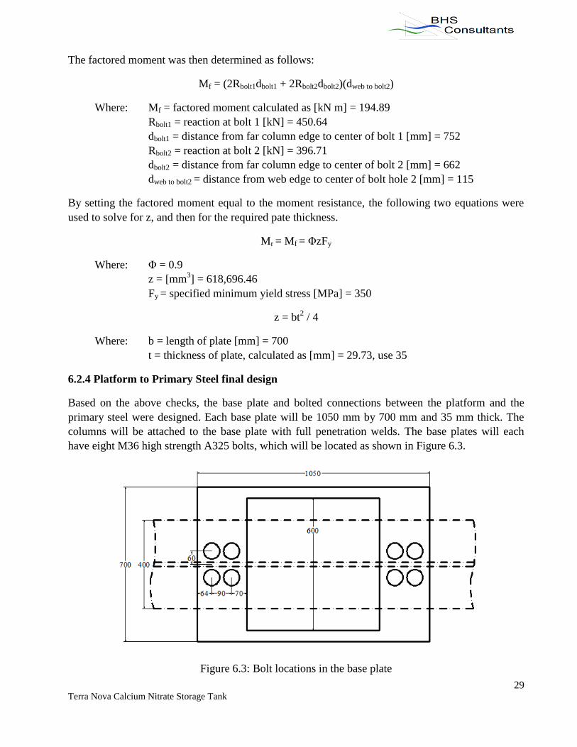
6.2.4 Platform to Primary Steel final design
Based on the above checks, the base plate and bolted connections between the platform and the
primary steel were designed. Each base plate will be 1050 mm by 700 mm and 35 mm thick. The
columns will be attached to the base plate with full penetration welds. The base plates will each
have eight M36 high strength A325 bolts, which will be located as shown in Figure 6.3.
Figure 6.3: Bolt locations in the base plate

30 Terra Nova Calcium Nitrate Storage Tank
7.0 Seafastening Design
Seafastening is the act of securing objects that are being transported on a vessel so that they are not
subject to movement. Movement during transportation is undesirable because it could cause
instability of the vessel and potentially damage the object, the vessel, and endanger the lives of the
crew. The design of seafastening is object and vessel specific based on vessel accelerations and
available padeye capacities.
Both the tank and the platform will have an individual seafastening design. The Maersk Nascopie
supply boat was used for the seasfastening design, as it will be shipping the tank and the platform to
the Terra Nova FPSO. The supply boat is equipped with attachment padeyes, or lugs, on framelines
every 5 m. Each lug can carry 2 tons of horizontal force.
It is assumed that the supply boat will be subject to a 0.5 g acceleration, which causes a 12 ton
horizontal force on both the tank and the platform based on their respective masses. The tank and
the platform will be equipped with eight chains for a total support of 16 tons during its transport to
the Terra Nova FPSO. The connection layouts are shown in Figure 7.1.
Figure 7.1: Tank and platform seafastening design

31 Terra Nova Calcium Nitrate Storage Tank
8.0 Lifting Design
Lifting assemblies are designed for the lift and transfer of the tank and platform from a supply
vessel to the Terra Nova FPSO. A lift assembly is used for the safe and efficient transfer of objects
offshore. The assembly consists of slings, master link, shackles and padeyes, and the design of all
these components is called the lifting design. The lift system is named for the number of padeyes,
and therefore liftpoints, on the object. Both the tank and the platform have four-point lift systems. A
typical four-point wire sling lifting assembly is shown in Figure 8.1.
Figure 8.1: Typical four-point wire sling lifting assembly (Det Norske Veritas 39)
8.1 Tank Lifting Design
The proof load is calculated to determine the Working Load Limit (WLL) of the slings, master link
and shackles for the purpose of their selection and the design of the lifting assembly. Two codes are
used for the lifting design. For the design of the sling assembly, including slings, shackles and
master link, Lloyd’s Register Code for Lifting Appliances in a Marine Environment (July 2008) was
used. The padeye design used DNV Standard for Certification No. 2.7-1 Offshore Containers (April
2006).
For the purpose of the proof load calculation, the Safe Working Load (SWL) is defined as the mass
(in metric tons) of the object being lifted.
32 Terra Nova Calcium Nitrate Storage Tank
SWLtank = mtank = 17.14 t
According to Table 9.1.1 of the Lloyd’s Register Code, the proof load is calculated as follows for 10
< SWL < 160 t:
Proof Loadtank = (1.04 * SWL) + 9.6 = 27.42 t
Based on note 4 from the same table, the proof load must be increased by the ratio of Fh/1.6 because
the lift occurs offshore, where Fh is the hoisting factor. The sea state number was found to be 5-6
based on the significant wave height for the SWL obtained from the Terra Nova FPSO crane access
drawing. The sea state number is used for Table 3.3.1 to determine the value of Fw as 21.7, where
Fw is the wave factor dependant on the design operational sea condition. Then Fh is calculated as
follows:
Fh = 0.83 + Fw * √(K/L1) = 2.07
Where: Fh = hoisting factor
Fw = wave factor
K = the crane system stiffness [N/mm]
L1 = live load [N]
√(K/L1) = 0.057 as given in the Lloyd’s code.
Once the factor of Fh/1.6 is applied to the proof loads, the new proof load for the tank becomes
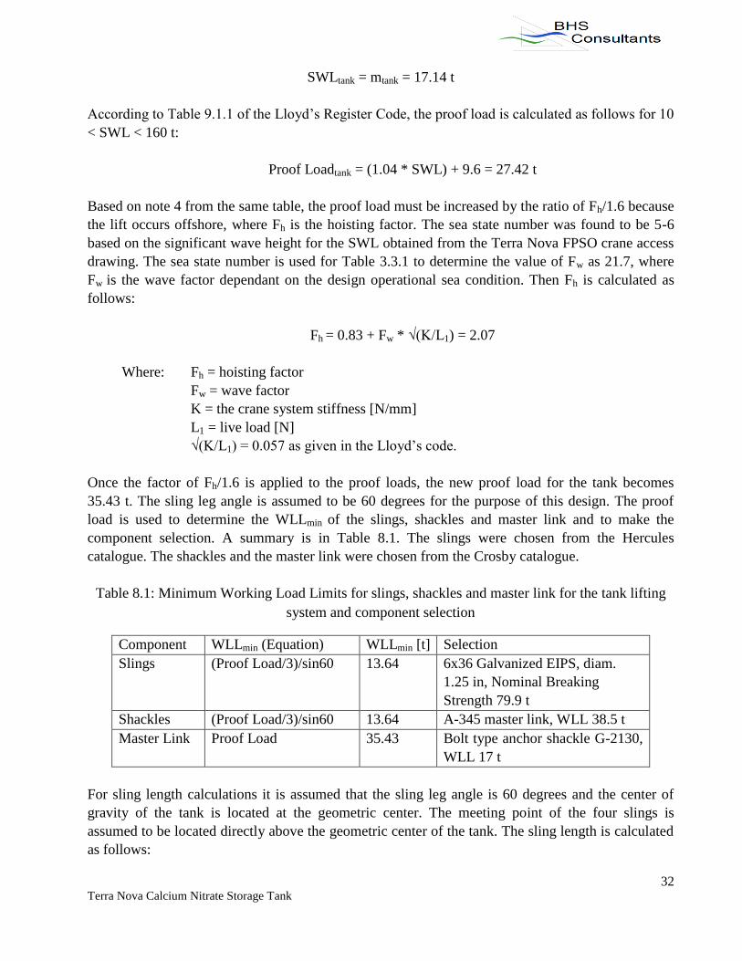
35.43 t. The sling leg angle is assumed to be 60 degrees for the purpose of this design. The proof
load is used to determine the WLLmin of the slings, shackles and master link and to make the
component selection. A summary is in Table 8.1. The slings were chosen from the Hercules
catalogue. The shackles and the master link were chosen from the Crosby catalogue.
Table 8.1: Minimum Working Load Limits for slings, shackles and master link for the tank lifting
system and component selection
Component WLLmin (Equation) WLLmin [t] Selection
Slings (Proof Load/3)/sin60 13.64 6x36 Galvanized EIPS, diam.
1.25 in, Nominal Breaking
Strength 79.9 t
Shackles (Proof Load/3)/sin60 13.64 A-345 master link, WLL 38.5 t
Master Link Proof Load 35.43 Bolt type anchor shackle G-2130,
WLL 17 t
For sling length calculations it is assumed that the sling leg angle is 60 degrees and the center of
gravity of the tank is located at the geometric center. The meeting point of the four slings is
assumed to be located directly above the geometric center of the tank. The sling length is calculated
as follows:

33 Terra Nova Calcium Nitrate Storage Tank
dLP to CoG = 0.5(widthtank) = 0.5(lengthtank) = 2525 mm
Where: dLP to CoG = distance from any liftpoint to the center of gravity [mm]
widthtank = lengthtank = 5050 mm
Lsling = (dLP to CoG) / cos(sling leg angle) = 5050 mm
Where: Lsling = length of sling at any liftpoint [mm]
dLP to CoG = distance from any liftpoint to the center of gravity [mm] = 2525
Sling leg angle [degrees] = 60
Finally, the padeyes located at each of the four lift points are designed. The padeye material is
350WT carbon steel, with a minimum yield strength of 350 MPa. The padeye dimensions were
chosen, and both the tear out stress and the contact stress were checked.
Tear out stress: Re ≥ ( 3 RSL ) / ( 2Ht –DHt )
Contact stress: Re ≥ 23.7 / √( RSL / DHt )
Where: Re = minimum specified yield strength of padeye material [N/mm2]
RSL = resulting sling load [N] = 133,769.24
H = shortest distance from bolt hole center to padeye edge [mm] = 100.00
DH = bolt hole diameter [mm] = 40.00
t = padeye thickness [mm] = 50.00
The tear out and contact stress checks were satisfied so the proposed design is acceptable.
The tension at the weld is calculated to determine the design length. The tensile resistance is set
equal to the tension force and the nominal area of the fusion face normal to the tensile force is
found. Then the area is used to determine the minimum length of the padeye.
Tr = ΦxAnFu = RSL
Where: Tr = factored tensile resistance [kN] = 133.77
Φx = 0.67
An = nominal area of fusion face normal to tensile force [mm2] = 570.44
Fu = specified minimum tensile strength [MPa] = 350
An = t * L
Where: An = nominal area of fusion face normal to tensile force [mm2] = 570.44
t = thickness of padeye [mm] = 50.00
L = minimum length of padeye [mm] = 11.41
34 Terra Nova Calcium Nitrate Storage Tank
The minimum length of the padeye is far too small to be the actual length. Therefore, a reasonable
assumption is made that the length is equal to twice the shortest distance from bolt hole center to
padeye edge, which is 200 mm.
The moment resistance of the padeye was calculated to determine the height to the center of the
padeye:
Mr = (1/SF)(bt2/6)Fy = 9.72 kN m
Where: Mr = moment resistance [kN m]
SF = safety factor = 3
b = length of the padeye [mm] = 200.00
t = thickness of padeye [mm] = 50.00
Fy = yield stress [MPa] = 350
Assuming the applied moment is equal to the moment resistance, the height to the center of the
padeye is determined as follows.
Mapplied = FH * x,
x = Hc + 0.5DH + (100 – DH/2) /2, and
Hc = 110 mm, use 105 mm
Where: Mapplied = applied moment [kN m] = Mr = 9.72
FH = horizontal component of RSL [kN] = 66.88
x = moment arm [mm] = 160.00
Hc = height to center of padeye [mm]
DH = bolt hole diameter [mm] = 40.00
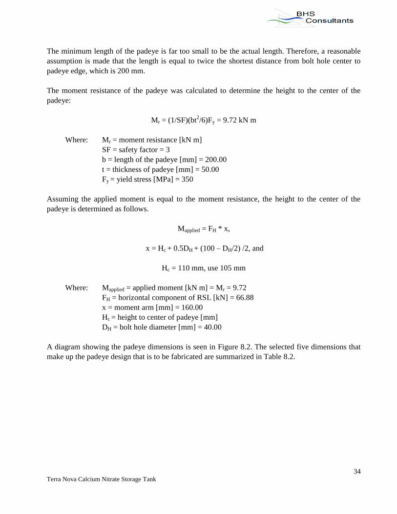
A diagram showing the padeye dimensions is seen in Figure 8.2. The selected five dimensions that
make up the padeye design that is to be fabricated are summarized in Table 8.2.

35 Terra Nova Calcium Nitrate Storage Tank
Figure 8.2: Padeye dimension diagram
Table 8.2: Padeye design dimensions for tank lifting system
Shortest distance from bolt hole center to padeye edge, H [mm] 100
Bolt hole diameter, DH [mm] 40
Padeye thickness, t [mm] 50
Height to center of padeye, Hc [mm] 105
Length of padeye, L [mm] 200
8.2 Platform Lifting Design
The lifting design for the platform follows the same procedure as above. The following values are
calculated.
SWLplatform = mplatform = 24 t
Proof Loadplatform = (1.04 * SWL) + 9.6 = 34.56 t
Fh = 0.83 + Fw * √(K/L1) = 2.07
Where: Fh = hoisting factor
Fw = wave factor
K = the crane system stiffness [N/mm]
L1 = live load [N]
Assuming √(K/L1) = 0.057 as given in the Lloyd’s code
Proof Loadplatform = (34.56 t)(Fh/1.6) = 44.65 t

36 Terra Nova Calcium Nitrate Storage Tank
Table 8.3: Minimum Working Load Limits for slings, shackles and master link for the platform
lifting system and component selection
Component WLLmin (Equation) WLLmin [t] Selection
Slings (Proof Load/3)/sin60 17.18 6x36 Galvanized EIPS, diam.
1.375 in, Nominal Breaking
Strength 96 t
Shackles (Proof Load/3)/sin60 17.18 A-345 master link, WLL 46.5 t
Master Link Proof Load 44.65 Bolt type anchor shackle G-
2130, WLL 25 t
For sling length calculations it is assumed that the sling leg angle is 60 degrees. The platform was
modeled in S-Frame to find the center of gravity and the sling lengths that will yield the proper sling
leg angle. The x and y coordinates of the center of gravity were found to be 4300 mm and 3850 mm,
respectively, as seen in Figure 8.3.
Figure 8.3: Platform diagram showing liftpoints, center of gravity and geometric center
Next, the distance from each liftpoint to the center of gravity was determined. Then sling lengths
were calculated as follows:
Lsling = (dLP to sling) / cos60

37 Terra Nova Calcium Nitrate Storage Tank
The distances from the liftpoints to the center of gravity and the sling lengths are summarized in
Table 8.4.
Table 8.4: Sling lengths for platform lifting system
Liftpoint (LP) Distance from LP to CoG, dLP to sling (mm) Sling Length, Lsling (mm)
1 3927.23 7854.46
2 2750.00 5500.00
3 3927.23 7854.46
4 4300.00 8600.00
Finally, the padeyes that were designed for the tank are used for the platform as well. Once again,
the padeye material is 350WT carbon steel, with a minimum yield strength of 350 MPa. The padeye
dimensions were chosen, and both the tear out stress and the contact stress were checked.
Tear out stress: Re ≥ ( 3 RSL ) / ( 2Ht –DHt )
Contact stress: Re ≥ 23.7 / √( RSL / DHt )
Where: Re = minimum specified yield strength of padeye material [N/mm2]
RSL = resulting sling load [N] = 180,139.94
H = shortest distance from bolt hole center to padeye edge [mm] = 100.00
DH = bolt hole diameter [mm] = 45.00
t = padeye thickness [mm] = 55.00
The tear out and contact stress checks were satisfied so the proposed design is acceptable.
The tension at the weld is calculated to determine the design length. The tensile resistance is set
equal to the tension force and the nominal area of the fusion face normal to the tensile force is
found. Then the area is used to determine the minimum length of the padeye.
Tr = ΦxAnFu = RSL
Where: Tr = factored tensile resistance [kN] = 180.14
Φx = 0.67
An = nominal area of fusion face normal to tensile force [mm2] = 768.19
Fu = specified minimum tensile strength [MPa] = 350
An = t * L
Where: An = nominal area of fusion face normal to tensile force [mm2] = 768.19
t = thickness of padeye [mm] = 55.00
L = minimum length of padeye [mm] = 13.97

38 Terra Nova Calcium Nitrate Storage Tank
The minimum length of the padeye is far too small to be the actual length. Therefore, a reasonable
assumption is made that the length is equal to twice the shortest distance from bolt hole center to
padeye edge, which is 200 mm.
The moment resistance of the padeye was calculated to determine the height to the center of the
padeye:
Mr = (1/SF)(bt2/6)Fy = 11.76 kN m
Where: Mr = moment resistance [kN m]
SF = safety factor = 3
b = length of the padeye [mm] = 200.00
t = thickness of padeye [mm] = 55.00
Fy = yield stress [MPa] = 350
Assuming the applied moment is equal to the moment resistance, the height to the center of the
padeye is determined as follows.
Mapplied = FH * x,
x = Hc + 0.5DH + (100 – DH/2) /2, and
Hc = 69.36 mm, use 65 mm
Where: Mapplied = applied moment [kN m] = Mr = 11.76
FH = horizontal component of RSL [kN] = 90.07
x = moment arm [mm] = 130.61
Hc = height to center of padeye [mm]
DH = bolt hole diameter [mm] = 45.00
A diagram showing the padeye dimensions is seen in Figure 8.2. The selected five dimensions that
make up the padeye design that is to be fabricated are summarized in Table 8.5.
Table 8.5: Padeye design dimensions for tank lifting system
Shortest distance from bolt hole center to padeye edge, H [mm] 100
Bolt hole diameter, DH [mm] 45
Padeye thickness, t [mm] 55
Height to center of padeye, Hc [mm] 65
Length of padeye, L [mm] 200

39 Terra Nova Calcium Nitrate Storage Tank
9.0 Cost
A cost estimate was completed for the tank and platform structures using RS Means, as well as
researched data. The various members for the structures will be fabricated as designed, so steel unit
weight was used to estimate the cost of the steel. In order to estimate the cost of 316L stainless steel,
a unit cost was found as $4.9/kg, and the unit cost of steel was found to be $0.6/kg. Therefore the
cost for steel bare material in RS Means was multiplied by a factor of eight (metal prices). The cost
estimate for the tank resulted in a total cost of $261,600.61 and the breakdown is displayed in Table
9.1. The cost estimate for the platform resulted in a total cost of $181,638.31, and the breakdown is
displayed in Table 9.2.
Table 9.1: Tank cost breakdown
Description Unit Quantity Cost
316L Stainless steel kg 17139 $ 78,668.01
Welding m 200 $ 102,070.00
E-3A Crew days 15 $ 80,862.60
Total $ 261,600.61
Table 9.2: Platform cost breakdown
Description Unit Quantity Cost
Structural tubing, heavy section,
including fabrication labour, shop
primer, cap and base plate, and bolts
kg 24013.81 $ 86,209.58
Welding m 53.3 $ 5,615.16
Railing, pipe, steel, primed, 31 mm dia,
shop fabricated m 26 $ 2,585.44
Ladder, shop fabricated, steel, including
cage m 9 $ 3,846.60
High strength bolt, , including washer &
nut Each 32 $ 344.64
Metal floor steel decking m2 49 $ 2,346.61
E-3A Crew days 2 $ 80,862.60
Total $ 181,638.31

40 Terra Nova Calcium Nitrate Storage Tank
10.0 Project Summary
Throughout the design of the calcium nitrate storage tank and the supporting platform the project
constraints were considered and accommodated. All project deliverables were met.
Abaqus, which is a finite element analysis modeling software, was used to model the storage tank.
The preliminary design was optimized to be most economical. The tank design included tank walls,
stiffeners and bulkheads. The final wall thickness was 8 mm. The stiffener thickness was 8 mm, and
they were placed at 750 mm intervals in all directions around the tank. The tank was designed to be
5.05 m by 5.05 m by 4.05 m. It has a weight of 17, 139 tons and a cost of $261,600.61 .
The platform was modeled in S-Frame and the preliminary design was optimized to meet all project criteria
and to be most cost-efficient. The columns, cross-bracing and corner-bracing are hollow sections, and the
deck is comprised of W sections. The design included the bolted connections through to the primary steel of
the Terra Nova FPSO. The final platform dimensions were 7.7 m by 7.05 m by 4.5 m. The final platform has
a weight of approximately 24 tons and a cost of $181,638.31.
The storage tank and supporting platform were designed in an efficient, safe and economical
manner and are capable of successful implementation offshore on the Terra Nova FPSO.

I Terra Nova Calcium Nitrate Storage Tank
References
Suncor Energy. (n.d.). Terra Nova. Retrieved from http://www.suncor.com/en/about/4001.aspx
Pinheiro, Angelo. (2011). “How to ensure H2S safety on offshore rigs.” Drilling Contractor.
Marathon Oil. Retreived on March 4, 2013 from http://www.drillingcontractor.org/how-to-
ensure-h2s-safety-on-offshore-rigs-8267
Statoil. (2011). “Offshore Fields in Production.” Annual Report 2011. Retrieved on March 4, 2013
from http://www.statoil.com/annualreport2011/en/ouroperations/businessareas/development
andproductioninternational(dpi)/internationalfields/pages/canada.aspx
Hamdan, Fadi. (2006). Structural strengthening of offshore topsides structures as part of explosion risk
reduction methods. Retrieved on Feb. 13, 2013 from http://www.hse.gov.uk/research/rrpdf/rr489.pdf.
Metal Prices. (2012). “Metal Prices”. Retrieved on March 26, 2013 from
http://www.metalprices.com/metal/stainless-steel/stainless-steel-flat-rolled-coil-316
Det Norske Veritas. (2006). Standard for certification no. 2.7-1: Offshore containers.
Lloyd's Register. (2008). Code for lifting appliances in a marine environment. London, UK: Lloyd's
Register.
Canadian Standards Association. (2007). National Standard of Canada CAN/CSA-Z19902-09:
Petroleum and natural gas industries - fixed steel offshore structures.