terminal d410 - scale service d410 terminal d410 advanced user manual code 813717 edition march 2004
TRANSCRIPT
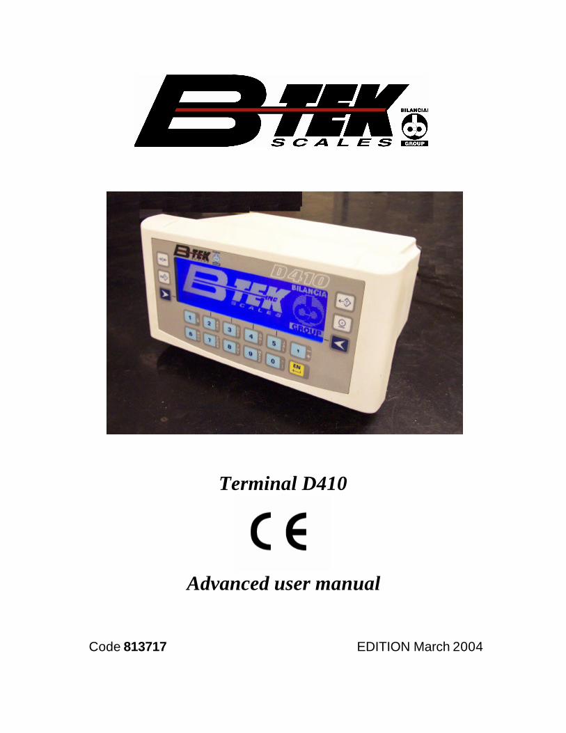
Terminal D410
Terminal D410
Advanced user manual
Code 813717 EDITION March 2004


Index9. FOREWORD TO THE ADVANCED USER MANUAL 2-7
10. PROGRAMMING OF SERIAL LINE COMMUNICATION 2-910.1 Symbols used 2-910.2 Strings 2-10
10.2.1 Cb (or Bilanciai) string 2-1010.2.2 Extended string 2-1110.2.3 Extraction string 2-1310.2.4 Visual string 2-1410.2.5 Idea string 2-1510.2.6 Cma 2-1510.2.7 On request with address 2-1510.2.8 Customized string 2-16
10.3 Protocols for cyclic strings 2-1710.3.1 ACK-NAK protocol 2-1710.3.2 Cyclic protocol 2-1710.3.3 On request protocol 2-17
10.4 Remote commands protocol 2-1810.4.1 Reply to an incorrect command 2-1810.4.2 Reply to a correct command 2-1910.4.3 Suspension of cyclic transmission 2-1910.4.4 Resumption of cyclic transmission 2-1910.4.5 Request for gross weight 2-1910.4.6 Request for net weight 2-1910.4.7 Request transmission of tare 2-2010.4.8 Request transmission of scale status 2-2010.4.9 Request transmission of scale status (version EV2001) 2-2210.4.10 Scale zeroing 2-2210.4.11 Tare acquisition 2-2210.4.12 Tare entering 2-2210.4.13 Cancellation of an entered tare 2-2310.4.14 Request transmission of general data table 2-2310.4.15 Request for general data item "n" 2-2310.4.16 Request to enter the value "y" in the general data item "n" 2-2310.4.17 Request for transmission of the net weight and the scale status
2-2310.4.18 Request for transmission of net weight and scale status with 6 bytes
2-2510.4.19 Request for transmission of the net weight, tare and scale statuswith 6 bytes 2-2610.4.20 Print request 2-2610.4.21 Read last weight acquired 2-2610.4.22 Cancel last acquired weight 2-2610.4.23 Request division value 2-2610.4.24 Request for net weight in high resolution 2-2710.4.25 Request for maximum capacity value 2-2710.4.26 Request for net weight without unit of measurement 2-2710.4.27 Lock keypad and display 2-2710.4.28 Unlock keypad and display 2-27
D410
2-3

10.4.29 Lock keypad 2-2810.4.30 Unlock keypad 2-2810.4.31 Remote commands with checksum 2-2810.4.32 Remote commands with addressing 2-29
10.5 Remote commands for Input/Output management 2-3010.5.1 How to set a single output 2-3010.5.2 How to zero-set a single output 2-3110.5.3 How to test a single output 2-3210.5.4 How to test a single input 2-3310.5.5 How to test all the outputs 2-3410.5.6 How to change the status of all the outputs 2-3610.5.7 How to test all the inputs 2-37
10.6 Remote commands for digital cells 2-3810.6.1 Request for cell points 2-3810.6.2 Request for cell temperature 2-3810.6.3 Request for version and release of cell software 2-3810.6.4 Request for power supply 2-3910.6.5 Request for cell serial numbers 2-3910.6.6 Request for angle calibration coefficient 2-3910.6.7 Request for number of cells in system 2-4010.6.8 Request for cell status 2-4010.6.9 Request for digital scale status 2-42
10.7 Communication in MPP operation 2-4410.7.1 Operation 2-4410.7.2 Weighing request from keypad with data transmission on completionof operation 2-4510.7.3 Weighing request from serial command with transmission oncompletion of operation 2-4810.7.4 Weighing request from keypad and transmission request from serialcommand 2-4810.7.5 Weighing and transmission request from serial command 2-4910.7.6 MP and MC remote commands with checksum 2-49
11. PERSONALIZATION 2-5111.1 Foreword 2-5111.2 Accessing the parameter configuration function 2-5111.3 Language 2-5111.4 Setup menu 2-52
11.4.1 Conditioned menu 2-5211.4.2 Entering numeric data 2-5211.4.3 Entering alphanumeric data 2-5211.4.4 Validating input data 2-5211.4.5 NOT MODIFIABLE parameter or menu 2-5311.4.6 NOT AVAILABLE parameter or menu 2-53
11.5 Overview of the menu tree 2-5311.6 Descriptions of the main menus and parameters 2-56
11.6.1 Setup Menu/Scale/Configurations/Metrological 2-5611.6.2 Setup Menu/Scale/Configurations/General menu 2-5711.6.3 Setup Menu/ANALOGUE scale/Analogue scale parameters 2-5811.6.4 Setup Menu/DIGITAL scale/Digital scale parameters 2-5811.6.5 Setup Menu/Scale/Calibration/Display data 2-5811.6.6 Setup Menu/Scale/Test 2-59
D410
2-4

11.6.7 Setup Menu/Personalizations/Operating modes 2-6111.6.8 Setup Menu/Personalizations/Operating modes /Printer/ Model 2-6311.6.9 Setup Menu/Personalizations/Operating modes /Printer/ Port 2-6711.6.10 Setup Menu/Personalizations/Operating modes/ Printer / Prints
2-6811.6.11 Setup Menu/Personalizations/Operating modes/MPP operation
2-7011.6.12 Setup Menu/Personalizations/Operating modes/Traffic light 2-7111.6.13 Setup Menu/Personalizations/Outputs/Serial/Com xy 2-7211.6.14 Setup Menu / Personalizations / Outputs / Serial / String /.../ Com xyconfiguration 2-7411.6.15 Setup Menu/Personalizations/Outputs/Input-Output 2-7511.6.16 Setup Menu/Personalizations/Outputs/Analogue output 2-7811.6.17 Setup Menu/Personalizations/Outputs/BCD 2-7811.6.18 Setup Menu/Personalizations/Messages 2-7911.6.19 List of modifiable messages 2-8011.6.20 Setup Menu/Personalizations/Shortcut keys 2-8311.6.21 Setup Menu/Personalizations/Texts 2-8511.6.22 Setup Menu/Personalizations/Files 2-8611.6.23 Setup Menu/Personalizations/Prints-Customized transmis.memorized 2-8711.6.24 Setup Menu/Personalizations/Backup-Restore 2-88
11.7 Test procedures 2-9111.7.1 Terminal Tests/Serial Ports 2-9111.7.2 Terminal Tests/Inputs-Outputs 2-9111.7.3 Terminal Tests/Keypad 2-9111.7.4 Terminal Tests/Terminal Configuration Report 2-9211.7.5 Terminal Tests/Analogue output 2-9211.7.6 Terminal Tests/Battery 2-92
11.8 Repeater scale 2-9311.8.1 Setup Menu/Repeater scale/Repeater scale parameters/Serialport/Com xy 2-9311.8.2 Setup Menu/Repeater scale/Repeater scale parameters/String 2-94
D410
2-5

D410
2-6
9. FOREWORD TO THE ADVANCED USERMANUALThis manual describes the procedures for terminal personalization inorder to adapt it to the specific weighing system in which it is installed.It contains the software commands used to interface the terminal with aPC, PLC and host computers in general.
WARNING The personalization operations described herein do not inany way influence weighing functions but, unless correctlyperformed, they may compromise the operation of thesystem as a whole. The operations described in this sectionof the manual should only be entrusted to qualifiedtechnicians with specialised experience in this field.
D410
2-7

D410
2-8

10. PROGRAMMING OF SERIAL LINECOMMUNICATION
10.1 Symbols usedThe following conventions are used to denote the characters used inserial line communication.
✔ Normal characters are indicated with their usual symbols.✔ Control characters appear in brackets and are written in uppercase.
For example:<CR> indicates the carriage return character.<SP> indicates the space character.
✔ Where necessary, the hexadecimal value of the character is given innumbers and uppercase letters.For example: <CR>(0DH) o $(24H).
✔ Variables are written in lower case between brackets.For example:<um>= unit of measurement.This may assume the following values:kg = kilogrammes<SP>g = grammeslb = pounds<SP>t = tonnes
✔ Numeric fields are indicated with n and y, and may include initialspaces, a decimal point and a minus sign.
D410
2-9

10.2 StringsThe terminal has two serial output ports which may be used for theconnection of external devices, such as printers, personal computers,PLCs, etc.. The user can choose the type of transmission protocol to beused from among those already present on the terminal. The user mayalso personalize the serial transmission parameters using the specificmenu (see par. 11.6.14 on page 2-74 ).
10.2.1 Cb (or Bilanciai) string
$(24H) start string character1st character
<s>2nd character s=stabilitys=0 weight stables=1 weight not stables=3 weight not valid (negative oroverload)
net weight3rd-7th
character if the weight consists of more than 5digits, the least significant digits willnot be transmitted;
<CR>(ODH) end string character8th character
The following protocols are available: Cyclic (see par. 10.3.2 on page2-17 ), On request (see par. 10.3.3 on page 2-17 ), ACK-NAK (see par. 10.3.1 on page 2-17 ).
D410
2-10
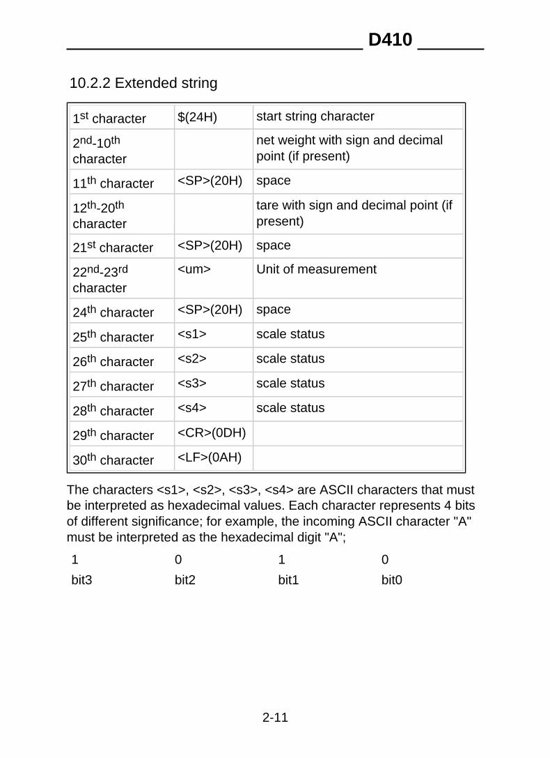
10.2.2 Extended string
$(24H) start string character1st character
net weight with sign and decimalpoint (if present)
2nd-10th
character
<SP>(20H) space11th character
tare with sign and decimal point (ifpresent)
12th-20th
character
<SP>(20H) space21st character
<um> Unit of measurement22nd-23rd
character
<SP>(20H) space24th character
<s1> scale status25th character
<s2> scale status26th character
<s3> scale status27th character
<s4> scale status28th character
<CR>(0DH)29th character
<LF>(0AH)30th character
The characters <s1>, <s2>, <s3>, <s4> are ASCII characters that mustbe interpreted as hexadecimal values. Each character represents 4 bitsof different significance; for example, the incoming ASCII character "A"must be interpreted as the hexadecimal digit "A";
01 0 1
bit0bit3 bit2 bit1
D410
2-11

When a bit assumes the value "1" the corresponding signal is "true"; thesignificance of the signals is as follows:
<s1> bit 0 minimum weighment signal
bit 1 tare locked signal
bit 2 tare preset(1)/self-weighed (0) entered signal
bit 3 centre zero signal
<s2> bit 0 LSB weighing extension signal (ME only)
bit 1 weight stable signal
bit 2 overload signal
bit 3 MSB weighing extension signal (ME only)
<s3> bit 0 tare entered signal
bit 1 tare locked cancelled signal (ME only)
bit 2 weight not valid
bit 3 printing in progress
<s4> bit 0 approved instrument
bit 1 converter fault
bit 2 scale configuration parameters error
bit 3 not utilised
The following protocols are available: Cyclic (see par. 10.3.2 on page2-17 ), On request (see par. 10.3.3 on page 2-17 ), ACK-NAK (see par. 10.3.1 on page 2-17 ), Remote commands (see par. 10.4 on page2-18 ).
D410
2-12

10.2.3 Extraction stringIn the case of loading or unloading extraction operation, the net weight
and tare (2nd to 10th characters and 12th to 20th characters in theExtended string) are replaced respectively by the extracted weight andgross weight characters.
$(24H) start string character1st character
0(30H) extracted weight with sign anddecimal point (if present)
2nd-10th
character
<SP>(20H) space11th character
gross weight with sign and decimalpoint (if present)
12th-20th
character
<SP>(20H) space21st character
<um> Unit of measurement22nd-23rd
character
<SP>(20H) space24th character
<s1> scale status (see note)25th character
<s2> scale status (see note)26th character
<s3> scale status (see note)27th character
<s4> scale status (see note)28th character
<CR>(0DH)29th character
<LF>(0AH)30th character
D410
2-13

10.2.4 Visual string
$(24H) start string character1st character
0(30H) fixed zero character2nd character
<s>3rd character s=stabilitys=0 weight stables=1 weight not stables=3 weight not valid (negative oroverload)
net weight with sign;4th-8th
character if the weight consists of more than 5digits, the least significant digits willnot be transmitted;if the value includes a decimal point,the length of the string will beincreased by 1 character
<CR>(0DH) end string character9th character
D410
2-14
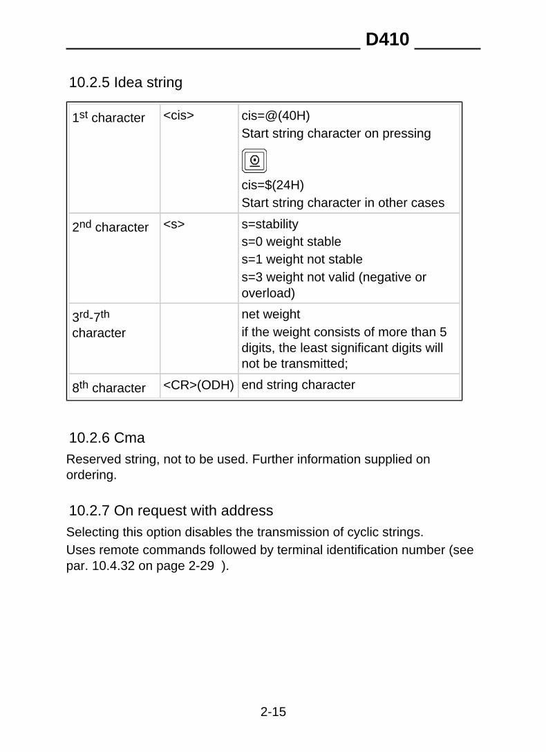
10.2.5 Idea string
<cis>1st character cis=@(40H)Start string character on pressing
cis=$(24H)Start string character in other cases
<s>2nd character s=stabilitys=0 weight stables=1 weight not stables=3 weight not valid (negative oroverload)
net weight3rd-7th
character if the weight consists of more than 5digits, the least significant digits willnot be transmitted;
<CR>(ODH) end string character8th character
10.2.6 CmaReserved string, not to be used. Further information supplied onordering.
10.2.7 On request with addressSelecting this option disables the transmission of cyclic strings.Uses remote commands followed by terminal identification number (see par. 10.4.32 on page 2-29 ).
D410
2-15
10.2.8 Customized stringThe string format may be customized using the program "Dialogic".For further information contact the Manufacturer.
D410
2-16

10.3 Protocols for cyclic strings
10.3.1 ACK-NAK protocolThe string is only sent on request of the user via the request
transmission key or from an external input (see par. 11.6.15 onpage 2-75 ). After transmission of the weight, the terminal behaves asfollows:
✔ if it receives the "ACK" character (06H) , it awaits a new transmissionrequest;
✔ if it receives the "NAK" character (15H), it sends the string againbecause the previous transmission was not completed successfully;
✔ if it receives three "NAK" characters in succession, the terminaldisplays the "NO ACK" message (transmission error).
10.3.2 Cyclic protocolThe selected string (see par. 10.2 on page 2-10 ) is transmittedcyclically at a rate of 3 times per second.
10.3.3 On request protocolThe selected string is transmitted:
✔ either on pressing the request transmission key ;✔ or on the activation of an input (see par. 11.6.15 on page 2-75 ).
D410
2-17

10.4 Remote commands protocolThere are a number of serial line commands with which variousoperations can be commanded from a remote device (PC, PLC etc.).
WARNING Remote commands are only enabled if the extended stringformat was selected during terminal configuration (see par.10.2.2 on page 2-11 ).
WARNING Remote commands are not executed if cyclic serialtransmission is in progress; in this case cyclic transmissionmust be suspended with the command "EX<CR>" beforegiving any other remote commands.
WARNING Insert a delay of a few ms between the reply to a commandand the next command.
10.4.1 Reply to an incorrect command??<CR><LF>This reply string is sent:
✔ if the command syntax is incorrect;✔ if the command cannot be executed.
D410
2-18
10.4.2 Reply to a correct commandIn the case of the command being accepted, if the command requeststhe transmission of information, the reply will consist of the transmissionof the requested data item; in other cases the reply will consist of thefollowing string:OK<CR><LF>
10.4.3 Suspension of cyclic transmissionThis command is not available with the RS485 protocol, in whichtransmission is on request onlyEX<CR>
10.4.4 Resumption of cyclic transmissionThis command is not available with the RS485 protocol, in whichtransmission is on request onlySX<CR>
10.4.5 Request for gross weightXB<CR>The terminal responds with the following string:n<SP><um><SP>B<CR><LF>
10.4.6 Request for net weightXN<CR>The terminal responds with the following string:n<SP><um><SP>NT<CR><LF>
D410
2-19

10.4.7 Request transmission of tareXT<CR>The terminal responds with the following string:n<SP><um><SP>TE<CR><LF>if the tare has been entered manually;n<SP><um><SP>TR<CR><LF>if the tare has been acquired.
10.4.8 Request transmission of scale statusXZ<CR>The terminal responds with the following string:<s1><s2><s3><s4><CR><LF>The characters s1, s2, s3 and s4 are ASCII characters which must beinterpreted as hexadecimal values. Each character represents 4 bits ofdifferent significance; for example, the incoming ASCII character "A"must be interpreted as the hexadecimal digit "A";
01 0 1
bit0bit3 bit2 bit1
D410
2-20

When a bit assumes the value "1" the corresponding signal is "true"; thesignificance of the signals is as follows:
<s1> bit 0 minimum weighment signal
bit 1 tare locked signal
bit 2 tare preset(1)/self-weighed (0) entered signal
bit 3 centre zero signal
<s2> bit 0 LSB weighing extension signal (ME only)
bit 1 weight stable signal
bit 2 overload signal
bit 3 MSB weighing extension signal (ME only)
<s3> bit 0 tare entered signal
bit 1 tare locked cancelled signal (ME only)
bit 2 weight not valid
bit 3 printing in progress
<s4> bit 0 approved instrument
bit 1 converter fault
bit 2 scale configuration parameters error
bit 3 not utilised
D410
2-21

10.4.9 Request transmission of scale status (version EV2001)XS<CR>In the case of a positive reply, the terminal responds with the followingstring:<s1><s2><CR><LF>The characters s1 and s2 are ASCII characters that must be interpretedas hexadecimal values.The bits indicate the scale status as follows.
<s1> bit 0 in range
bit 1 weight stable
bit 2 centre zero
bit 3 displayed net weight
<s2> bit 0 not utilised
bit 1 not utilised
bit 2 not utilised
bit 3 print request: the print key has been pressed orinput n° 3 is activated.
10.4.10 Scale zeroingAZ<CR>
10.4.11 Tare acquisitionAT<CR>
10.4.12 Tare enteringnAT<CR>The command AT must be preceded by a weight expressed in amaximum of 7 characters comprising the decimal point, if present.
D410
2-22

10.4.13 Cancellation of an entered tareCT<CR>This command cancels any tare value in memory.
10.4.14 Request transmission of general data tableND<CR>The terminal responds to this command with a sequence of stringsterminating in <CR><LF> each containing the number of the data itemand its description; the following is an example data table:1 Date2 Time3 Extracted4 Gross5 Tare6 Net7 Status
10.4.15 Request for general data item "n"Xln<CR>With this command it is possible to read the current value of any of thegeneral data.
10.4.16 Request to enter the value "y" in the general data item"n"yXln<CR>where "y" is the value you wish to assign to the data item "n". Obviouslythe value to be entered must conform to the format of the data item.Values for some of the general data cannot be entered (e.g. grossweight, net weight, scale status, etc).
D410
2-23

10.4.17 Request for transmission of the net weight and thescale statusXn<CR>N.B.: the command sent is comprised of an uppercase X and lowercasen (not to be confused with generic significance assigned to thelowercase n described in par. 10.1 on page 2-9 ).In the case of a positive reply, the terminal responds with the followingstring:n<SP><um><SP><s1><s2><s3><s4><CR><LF>The characters s1, s2, s3 and s4 are ASCII characters the meaning ofwhich is explained in par. 10.4.8 on page 2-20 .
D410
2-24

10.4.18 Request for transmission of net weight and scalestatus with 6 bytesYS<CR>
When the command is received, the terminal replies with the followingstring:
n<SP><um><SP><s1><s2><s3><s4><s5><s6><CR><LF>
The meaning of the <s1>, <s2>, <s3> and <s4> bits is described in par.10.4.8 on page 2-20 .The meaning of the <s5> and <s6> bits is as follows:
<s5> bit 0 not utilised
bit 1 not utilised
bit 2 battery low indication
bit 3 Print made, weight acquired
<s6> bit 0 tare changed
bit 1 not utilised
bit 2 not utilised
bit 3 not utilised
The bit2 of <s5> is zero-set immediately after the 6 byte statustransmission.The bit3 of <s5> is zero-set immediately after the CP remote commandhas been received ( par. 10.4.22 on page 2-26 ). You can read the lastweight acquired by means of the PA command ( par. 10.4.21 on page2-26 ).The bit0 of <s6> is zero-set after the response has been transmitted toremote command XT ( par. 10.4.7 on page 2-20 ) or YT ( par. 10.4.19on page 2-26 ).Remember that in multi-expansion terminals, the tare is rounded off tothe extension change but the changed tare bit is not altered (theoperator must ask for the tare whenever the extension changes; thischange can be checked through bit0 and bit3 of <s2>).
D410
2-25

10.4.19 Request for transmission of the net weight, tare andscale status with 6 bytesYT<CR>
When the command is received, the terminal replies with the followingstring:
n<SP><um>y<SP><um><SP><s1><s2><s3><s4><s5><s6><CR><LF>
where:n = net weighty = tare
The meaning of the <s1>, <s2>, <s3>, <s4>, <s5> and <s6> bits hasbeen described previously ( par. 10.4.18 on page 2-25 and par. 10.4.8on page 2-20 ).
10.4.20 Print requestPR<CR>Any "printing not performed" message will be signalled only on thedisplay.
10.4.21 Read last weight acquiredPA<CR>The terminal responds by sending the last net weight to be acquired bypressing the print key or in response to the remote command PR; thereply string is as follows:n<SP><um><SP>PA<CR><LF>
10.4.22 Cancel last acquired weightCP<CR>
10.4.23 Request division valueXe<CR>The terminal responds with the string:e= n<SP><um><CR><LF>
D410
2-26

10.4.24 Request for net weight in high resolutionYN<CR>The reply string is:n<SP>y<SP><um><SP><s1><s2><s3><s4><CR><LF>n= net weighty= net weight in high resolutions1,s2,s3,s4=see STATUS in extended string ( par. 10.2.2 on page 2-11).
10.4.25 Request for maximum capacity valueXM<CR>The reply string is:Max= n<SP><um><CR><LF>
10.4.26 Request for net weight without unit of measurementYP<CR>The reply string is:n<CR><LF>where:n= significant digits of weight onlyThis string does not include the unit of measurement and insignificantleading zeroes are not transmitted.
10.4.27 Lock keypad and displayLD<CR>The message "DISPLOCK" is displayed in place of the weight and allkeys are disabled.
10.4.28 Unlock keypad and displayUD<CR>The keypad and display are re-enabled.
D410
2-27
10.4.29 Lock keypadLK<CR>Only the keypad is locked and the terminal displays the message"KEYLOCK ".
10.4.30 Unlock keypadUK<CR>The keypad is unlocked.
10.4.31 Remote commands with checksumManagement of remote commands with checksum can be enabledduring the installation phase ( par. 11.6.13 on page 2-72 ).Checksum mode increases security when the terminal and PC dialoguewith each other since the following precautions are taken:
✔ each remote command transmitted to the terminal must contain twochecksum characters in a dedicated position;
✔ each reply with data that the terminal transmits to the PC after aremote command must contain two checksum characters in adedicated position.
The position of the two checksum characters is immediately prior to the<CR> character..Checksum calculation involves making the XOR (exclusive OR) of all thecharacters in the string up to the first checksum character excluded. Theresult is expressed by two hexadecimal characters.An example of a gross weight transmission with checksum is givenbelow:
XB chk1chk2 <CR>
where, supposing that value 1A is obtained from XOR:chk1 is the first checksum character ("1" or rather 31H)chk2 is the second checksum character ("A" or rather 41H).
The terminal replies with the following string:
n<SP><um><SP>B chk1chk2 <CR><LF>
D410
2-28
10.4.32 Remote commands with addressingWhen using the string "On request with address" or if the RS485communication interface is selected, the remote commands described in par. 10.4 on page 2-18 will also have to include the number of theterminal to be interrogated..The system is comprised of one Master terminal (e.g. a PC) and anumber of Slave terminals (e.g. weighing terminals).Each weighing terminal is identified by a unique "terminal number" (see par. 11.6.13 on page 2-72 ).In this way you can create a network of weighing terminals that can beinterrogated by the Master terminal.The syntax of the remote commands has to be modified by the additionof the two characters of the terminal number.For example, the gross weight transmission command XB <CR>becomes XB 01 <CR> to indicate that the request from the Masterterminal is addressed to the terminal number 01.Similarly, in checksum mode the gross weight transmission commandbecomes XB01 chk1 chk2 <CR>.No reply will be sent by the terminal if there are checksum errors.
D410
2-29

10.5 Remote commands for Input/Output management
10.5.1 How to set a single outputOutput n2 of slot n1 can be set by means of the following command:
SO n1 n2 <CR>
where:
n1 is 1 hexadecimal character that defines the slot position of the output;n2 is 1 hexadecimal character that defines the number of the output onslot n1.
n1 = 0 (30H) output on the terminaln1 = 1 (31H) output on slot 1n1 = 2 (32H) output on slot 2
n2 = 1 (31H) output number 1n2 = 2 (32H) output number 2n2 = 3 (33H) output number 3n2 = 4 (34H) output number 4
D410
2-30
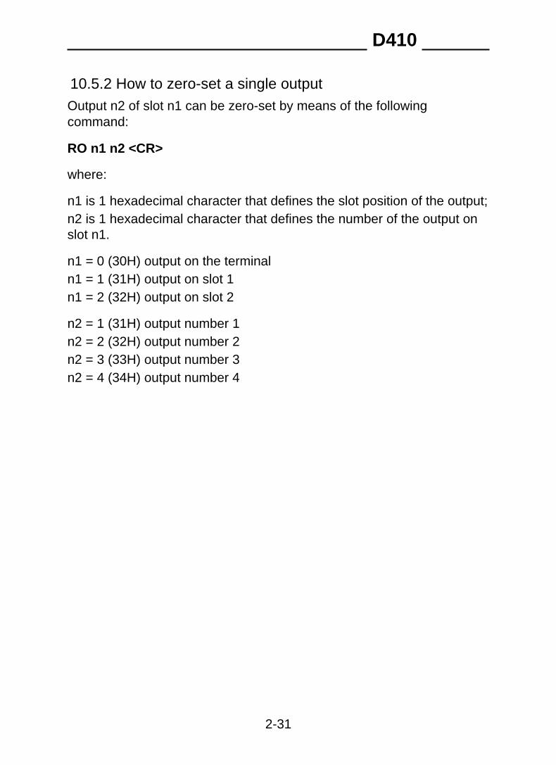
10.5.2 How to zero-set a single outputOutput n2 of slot n1 can be zero-set by means of the followingcommand:
RO n1 n2 <CR>
where:
n1 is 1 hexadecimal character that defines the slot position of the output;n2 is 1 hexadecimal character that defines the number of the output onslot n1.
n1 = 0 (30H) output on the terminaln1 = 1 (31H) output on slot 1n1 = 2 (32H) output on slot 2
n2 = 1 (31H) output number 1n2 = 2 (32H) output number 2n2 = 3 (33H) output number 3n2 = 4 (34H) output number 4
D410
2-31

10.5.3 How to test a single outputThe status of each output can be requested by means of the followingcommand:
TO n1 n2 <CR>
where:
n1 is 1 hexadecimal character that defines the slot position of the output;n2 is 1 hexadecimal character that defines the number of the output onslot n1.
n1 = 0 (30H) output on the terminaln1 = 1 (31H) output on slot 1n1 = 2 (32H) output on slot 2
n2 = 1 (31H) output number 1n2 = 2 (32H) output number 2n2 = 3 (33H) output number 3n2 = 4 (34H) output number 4
The terminal replies with one of the following messages:
✔ 1<CR><LF> if the output is activated;✔ 0<CR><LF> if the output is not activated;✔ -<CR><LF> if there is no slot.
D410
2-32

10.5.4 How to test a single inputThe status of each input can be requested by means of the followingcommand:
TI n1 n2 <CR>
where:
n1 is 1 hexadecimal character that defines the slot position of the input;n2 is 1 hexadecimal character that defines the number of the input onslot n1.
n1 = 0 (30H) input on the terminaln1 = 1 (31H) input on slot 1n1 = 2 (32H) input on slot 2
n2 = 1 (31H) input number 1n2 = 2 (32H) input number 2n2 = 3 (33H) input number 3n2 = 4 (34H) input number 4
The terminal replies with one of the following messages:
✔ 1<CR><LF> if the input is activated;✔ 0<CR><LF> if the input is not activated;✔ -<CR><LF> if there is no slot.
D410
2-33

10.5.5 How to test all the outputsThe status of all the slot outputs can be requested by means of thefollowing command:
LO<CR>
The terminal replies with the following string:
n1n2n3<CR><LF>
where:
n1 is 1 character that is the logic combination of the status (0 or 1) of theoutputs (max. 2) on the terminal. Its values can be 0 0 (30H) to 3 (33H).
n2 is 1 character that is the logic combination of the status (0 or 1) of theoutputs (max. 4) on slot 1. Its values can be 0 (30H) to F (46H). If thereis no slot 1, the value of n2 will be " - " (2DH).
n3 is a character that is the logic combination of the status (0 or 1) of theoutputs (max. 4) on slot 2. Its values can be 0 (30H) to F (46H). If thereis no slot 1, the value of n2 will be " - " (2DH).
The lines will be arranged in the following way:
bit0bit3 bit2 bit1
line 1line 4 line 3 line 2
where the values of the lines are 0 or 1.
For example, if the following command is received:
184<CR><LF>
1 8 4
01 1000 0100
D410
2-34

where:
01 lines on slot 1: line 1 activated (bit 0 = 1), line 2 (bit 1 = 0) notactivated;1000 lines on terminal: line 1 (bit 0 = 0), 2 (bit 1 = 0), 3 (bit 2 = 0) notactivated, line 4 (bit = 1) activated;0100 lines on slot 2: line 1 (bit 0 = 0), 2 (bit 1 = 0), 4 (bit 3 = 0) notactivated, line 3 (bit 2 = 1) activated.
D410
2-35

10.5.6 How to change the status of all the outputsThe status of all the slot outputs can be changed by means of thefollowing command:
n1n2n3WO<CR>
where:
n1 is 1 character that is the logic combination of the status (0 or 1) of theoutputs (max. 2) on the terminal. Its values can be 0 (30H) to 3 (33H).
n2 is 1 character that is the logic combination of the status (0 or 1) of theoutputs (max. 4) on slot 1. Its values can be 0 (30H) to F (46H).
n3 is a character that is the logic combination of the status (0 or 1) of theoutputs (max. 4) on slot 2. Its values can be 0 (30H) to F (46H).
D410
2-36

10.5.7 How to test all the inputsThe status of all the slot inputs can be requested by means of thefollowing command:
LI<CR>
The terminal replies with the following string:
n1n2n3<CR><LF>
where:
n1 is 1 character that is the logic combination of the status (0 or 1) of theinputs (max. 2) on the terminal. Its values can be 0 (30H) to 3 (33H).
n2 is 1 character that is the logic combination of the status (0 or 1) of theinputs (max. 4) on slot 1. Its values can be 0 (30H) to F (46H). If there isno slot 1, the value of n2 will be " - " (2DH).
n3 is a character that is the logic combination of the status (0 or 1) of theinputs (max. 4) on slot 2. Its values can be 0 (30H) to F (46H). If there isno slot 1, the value of n2 will be " - " (2DH).
D410
2-37

10.6 Remote commands for digital cellsThe following conventions will now be used besides the symbols alreadygiven in par. 10.1 on page 2-9 :
✔ c number that identifies the digital cell;✔ n and m indicate numerical fields with possible spaces at the
beginning, decimal separator, - sign and + sign.
10.6.1 Request for cell pointsDPc<CR>
The terminal replies with this string:
n<CR><LF>
n = number of points (0 to 200000)
10.6.2 Request for cell temperatureDTc<CR>
The terminal replies with this string:
n<CR><LF>
n = cell temperature in °C (- 40.0 to 100.0)
10.6.3 Request for version and release of cell softwareDVc<CR>
The terminal replies with this string:
n<SP>m<CR><LF>
n = cell software versionm = cell software release
D410
2-38

10.6.4 Request for power supplyDAc<CR>
The terminal replies with this string:
n<SP>m<CR><LF>
n = cell power supply voltage rating;m = strain gauge power supply voltage rating.
10.6.5 Request for cell serial numbersDMc<CR>
The terminal replies with this string:
n<SP>m<CR><LF>
n = cell serial number recorded on the cellm = cell serial number recorded on the terminal
10.6.6 Request for angle calibration coefficientDCc<CR>
The terminal replies with this string:
n<SP>m<CR><LF>
n = angle calibration coefficient loaded in cellm = angle calibration coefficient loaded in terminal
n and m can also take on the exponential format in this case.
D410
2-39

10.6.7 Request for number of cells in systemDN<CR>
The terminal replies with this string:
n<CR><LF>
n = number of cells that form the system
10.6.8 Request for cell statusDSc<CR>
The terminal replies with this string:
<s1><s2><s3><s4><CR><LF>
Characters s1, s2, s3, s4 are ASCII characters that must be interpretedas hexadecimal value. Each character represents 4 bits with differentmeanings. For example, the ASCII "A" character on the input must beinterpreted as hexadecimal figure "A":
01 0 1
bit0bit3 bit2 bit1
D410
2-40

When the value of a bit is "1", this means that the corresponding signalis in the true status. The meaning of the signals is as follows:
<s1> bit 0 temperature error
bit 1 not utilised
bit 2 not utilised
bit 3 not utilised
<s2> bit 0 cell not connected
bit 1 cell not configured
bit 2 serial number error
bit 3 voltage error
<s3> bit 0 reserved
bit 1 reserved
bit 2 not utilised
bit 3 cell in warm up status
<s4> bit 0 offset
bit 1 temperature reading phase
bit 2 voltage reading phase
bit 3 calibration reading phase
D410
2-41

10.6.9 Request for digital scale statusDB<CR>
The terminal replies with this string:
<s1><s2><s3><s4><CR><LF>
Characters s1, s2, s3, s4 are ASCII characters that must be interpretedas hexadecimal value. Each character represents 4 bits with differentmeanings. For example, the ASCII "A" character on the input must beinterpreted as hexadecimal figure "A":
01 0 1
bit0bit3 bit2 bit1
D410
2-42

When the value of a bit is "1", this means that the corresponding signalis in the true status. The meaning of the signals is as follows:
<s1> bit 0 not utilised
bit 1 not utilised
bit 2 not utilised
bit 3 not utilised
<s2> bit 0 voltage error in a cell
bit 1 not utilised
bit 2 not utilised
bit 3 not utilised
<s3> bit 0 at least one cell with temperature value off-range
bit 1 new system
bit 2 scale board replaced
bit 3 one single cell in multiple cell system replaced
<s4> bit 0 at least one cell not connected
bit 1 at least one cell not configured
bit 2 at least one cell with serial number error
bit 3 cell power supply voltage error
D410
2-43

10.7 Communication in MPP operation
10.7.1 OperationTerminals equipped with the MPP option can operate in the four differentmodes described in the following paragraphs.The operating mode used for MPP memory operation is selected duringinstallation ( par. 11.6.11 on page 2-70 ).
D410
2-44

10.7.2 Weighing request from keypad with data transmissionon completion of operationAfter having enabled the MPP memory (consult the Options chapter ofthe user manual), load the weight onto the scale, wait for weight stable
signal, then press .The terminal will save the weight data in memory and then transmitthem.If the Standard item has been selected in the Setup Menu ( par.11.6.11 on page 2-70 ), the data transmitted are:
$(24H)1st character
M(4DH)2nd character
P(50H)3rd character
MPP identification code or scalestatus indications:
4th-10th
characterNO<SP>STAB weight not stableNO<SP>VAL<SP> weight not validERRMEM<SP> weightmemorisation error
Weight with sign and decimal point,if present
11th-18th
character
<um> Unit of measurement19th-20th
character
<CRC>21st-22nd
characterString check field; calculated byperforming an XOR operation(exclusive OR) of all the precedingcharacters. The value calculated isexpressed in two hexadecimalcharacters, e.g. if the result is 62H,the two checksum characters are"6" (36H) and "2" (32H).
D410
2-45
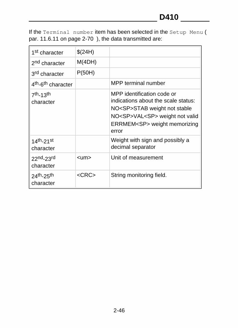
If the Terminal number item has been selected in the Setup Menu (par. 11.6.11 on page 2-70 ), the data transmitted are:
$(24H)1st character
M(4DH)2nd character
P(50H)3rd character
MPP terminal number4th-6th character
MPP identification code orindications about the scale status:
7th-13th
characterNO<SP>STAB weight not stableNO<SP>VAL<SP> weight not validERRMEM<SP> weight memorizingerror
Weight with sign and possibly adecimal separator
14th-21st
character
<um> Unit of measurement22nd-23rd
character
<CRC> String monitoring field.24th-25th
character
D410
2-46

If the Serial Number item has been selected in the Setup Menu (par. 11.6.11 on page 2-70 ), the data transmitted are:
$(24H)1st character
M(4DH)2nd character
P(50H)3rd character
Serial number4th-11th
character
MPP identification code orindications about the scale status:
12th-18th
characterNO<SP>STAB weight not stableNO<SP>VAL<SP> weight not validERRMEM<SP> weight memorizingerror
Weight with sign and possibly adecimal separator
19th-26th
character
<um> Unit of measurement27th-28th
character
<CRC> String monitoring field.29th-30th
character
The computer replies with:
✔ <ACK> if the string has arrived correctly;✔ <NAK> if the string has not arrived correctly; in which case the
terminal retransmits the data packet. After three negative replies orno reply, the terminal displays an error message.
Any characters other than <ACK> and <NAK> are interpreted as<NAK>.
WARNING The ACK/NACK protocol (see par. 10.3.1 on page 2-17 ) isautomatically enabled in MPP operation.
D410
2-47

10.7.3 Weighing request from serial command withtransmission on completion of operationAfter having loaded the weight on the scale, send the memorise weightand data request command via the computer:MP<CR>If the response is affirmative, the terminal will transmit one of the stringsdescribed in par. 10.7.2 on page 2-45 in the same mode, dependingon the item selected in the Setup menu (Standard, Terminal number,Serial number).
10.7.4 Weighing request from keypad and transmissionrequest from serial commandAfter loading the weight on the scale, wait for the weight stable indication
and then press ; the terminal will memorise the data.The computer may request the weight data from the terminal with thecommand:MP<CR>The weighing terminal replies:
✔ with one of the strings described in par. 10.7.2 on page 2-45 ;✔ NP<CR><LF>
if no weight has been memorised;The data may requested more than once with the command MP<CR>.At the end of the operation, the computer must transmit the command toenable the terminal to carry out a new weighing operation:MC<CR>
D410
2-48

10.7.5 Weighing and transmission request from serialcommandAfter loading the weight on the scale, send the memorise weightcommand from the computer:MP<CR>
Once the weight validity conditions are satisfied, the terminal memorisesthe data.The external computer must then transmit the data request command:MP<CR>The terminal responds with the string described in par. 10.7.2 on page2-45 .
10.7.6 MP and MC remote commands with checksumRemote commands MP and MC modify their structure for entry of thechecksum characters. Their format becomes the one below:MP 1 D <CR>MC 0 E <CR>
D410
2-49

D410
2-50

11. PERSONALIZATION
11.1 Foreword
WARNING Personalization procedures are strictly reserved forspecialised personnel only.However, the user is permitted to modify certain of theterminal operating parameters.We recommend that extreme care is taken when modifyingthese parameters to prevent possible malfunctions causedby incorrect settings.The only parameters that may be modified are those directlyrelated to the program installed on the terminal.
11.2 Accessing the parameter configuration functionTo access non-metrological parameters only:
✔ press on switching on the terminal.
11.3 LanguageOn entering setup, you can select the language in which you want themenu to be displayed.After selecting the setup menu language, the following information isbriefly displayed:
✔ program code✔ version✔ serial number of terminal (if other than zero, it will match the s/n
(serial number) on the data plate).
D410
2-51

11.4 Setup menuThe personalization parameters menu is a tree structure which can befollowed from the roots to the branches using the navigation keysdescribed in the Use of the terminal chapter of the user manual.
11.4.1 Conditioned menuDuring the parameter personalization procedure, the menu adaptsaccording to the selections made. Some parameters will therefore not bedisplayed as they are not required in the selected configuration.
11.4.2 Entering numeric dataSee the Use of the terminal chapter of the user manual.
11.4.3 Entering alphanumeric dataSee the Use of the terminal chapter of the user manual.
11.4.4 Validating input dataAll data entered are validated and if they do not fall within the permittedranges, an error message is displayed and you are asked to enter thedata again.
D410
2-52
11.4.5 NOT MODIFIABLE parameter or menuThe message "not modifiable" indicates that the parameter displayedcannot be modified if the setup menu was accessed by pressing therelative key on power up.
11.4.6 NOT AVAILABLE parameter or menuThe message "not available" indicates that the parameter will only beavailable in future versions.
11.5 Overview of the menu treeThe menu tree expanded to the third level is reported below. For details,refer to the specific paragraphs in this section or the installation sectionof the manual.
D410
2-53
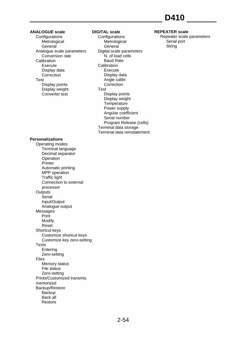
REPEATER scaleANALOGUE scale DIGITAL scaleConfigurations Repeater scale parametersConfigurations
Serial portMetrological MetrologicalGeneralGeneral String
Analogue scale parameters Digital scale parametersN. of load cellsConversion rateBaud RateCalibration
CalibrationExecuteExecuteDisplay dataDisplay dataCorrectionAngle calibr.TestCorrectionDisplay points
TestDisplay weightDisplay pointsConverter testDisplay weightTemperaturePower supplyAngular coefficientSerial numberProgram Release (cells)
Terminal data storageTerminal data reinstatement
PersonalizationsOperating modes
Terminal languageDecimal separatorOperationPrinterAutomatic printingMPP operationTraffic lightConnection to externalprocessor
OutputsSerialInput/OutputAnalogue output
MessagesPrintModifyReset
Shortcut keysCustomize shortcut keysCustomize key zero-setting
TextsEnteringZero-setting
FilesMemory statusFile statusZero-setting
Prints/Customized transmis.memorizedBackup/Restore
BackupBack allRestore
D410
2-54

Terminal testSerial ports
Serial communication portsCom01Com02
Inputs/outputsManualAutomatic
KeypadTerminal configuration portAnalogue output
Voltage calibr.Current calibr.Complete calibr.
BatteryUpgrade
Serial lineMaintenance
Serial numberInizializationCancel MPP BoardInizialize MPP codesTest reportCopy programme on boardCell emergency routineReserved
D410
2-55

11.6 Descriptions of the main menus and parametersUnless specified differently, the description of the parameters given inthe following paragraphs is valid for both analogue and digital scales.
11.6.1 Setup Menu/Scale/Configurations/MetrologicalThe metrological parameters entered during the installation phase canbe displayed (but not modified).
D410
2-56
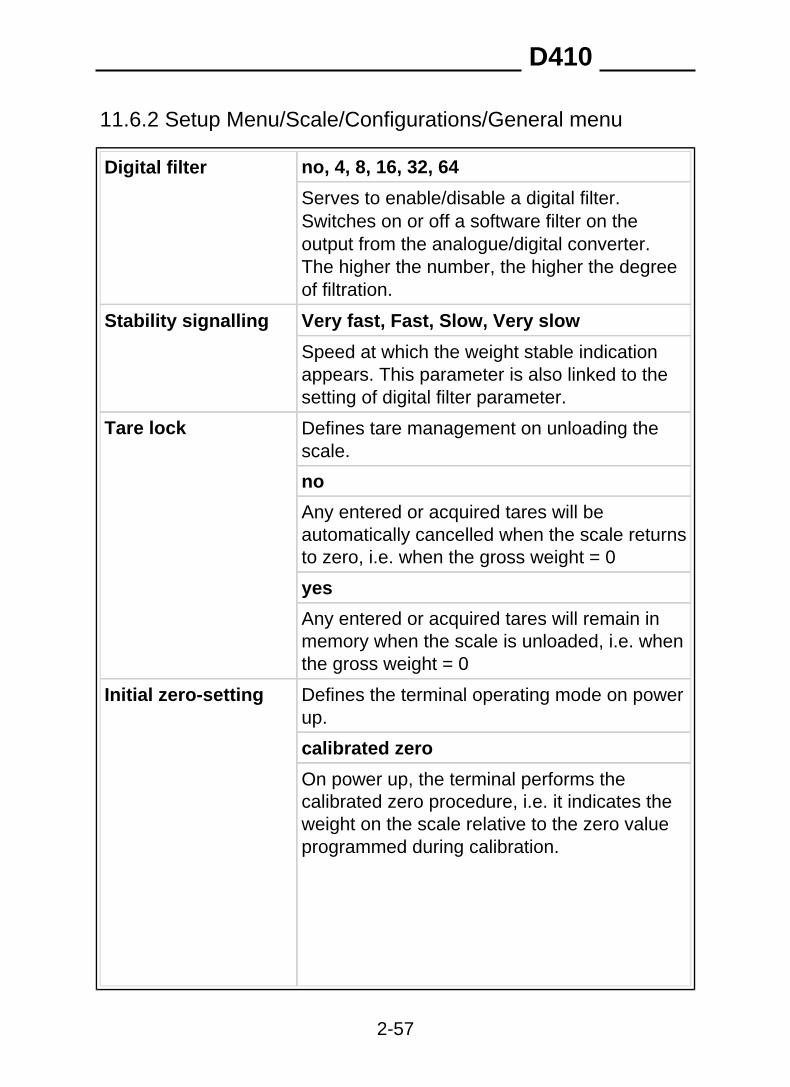
11.6.2 Setup Menu/Scale/Configurations/General menu
no, 4, 8, 16, 32, 64Digital filter
Serves to enable/disable a digital filter.Switches on or off a software filter on theoutput from the analogue/digital converter.The higher the number, the higher the degreeof filtration.
Very fast, Fast, Slow, Very slowStability signalling
Speed at which the weight stable indicationappears. This parameter is also linked to thesetting of digital filter parameter.
Tare lock Defines tare management on unloading thescale.
no
Any entered or acquired tares will beautomatically cancelled when the scale returnsto zero, i.e. when the gross weight = 0
yes
Any entered or acquired tares will remain inmemory when the scale is unloaded, i.e. whenthe gross weight = 0
Initial zero-setting Defines the terminal operating mode on powerup.
calibrated zero
On power up, the terminal performs thecalibrated zero procedure, i.e. it indicates theweight on the scale relative to the zero valueprogrammed during calibration.
D410
2-57
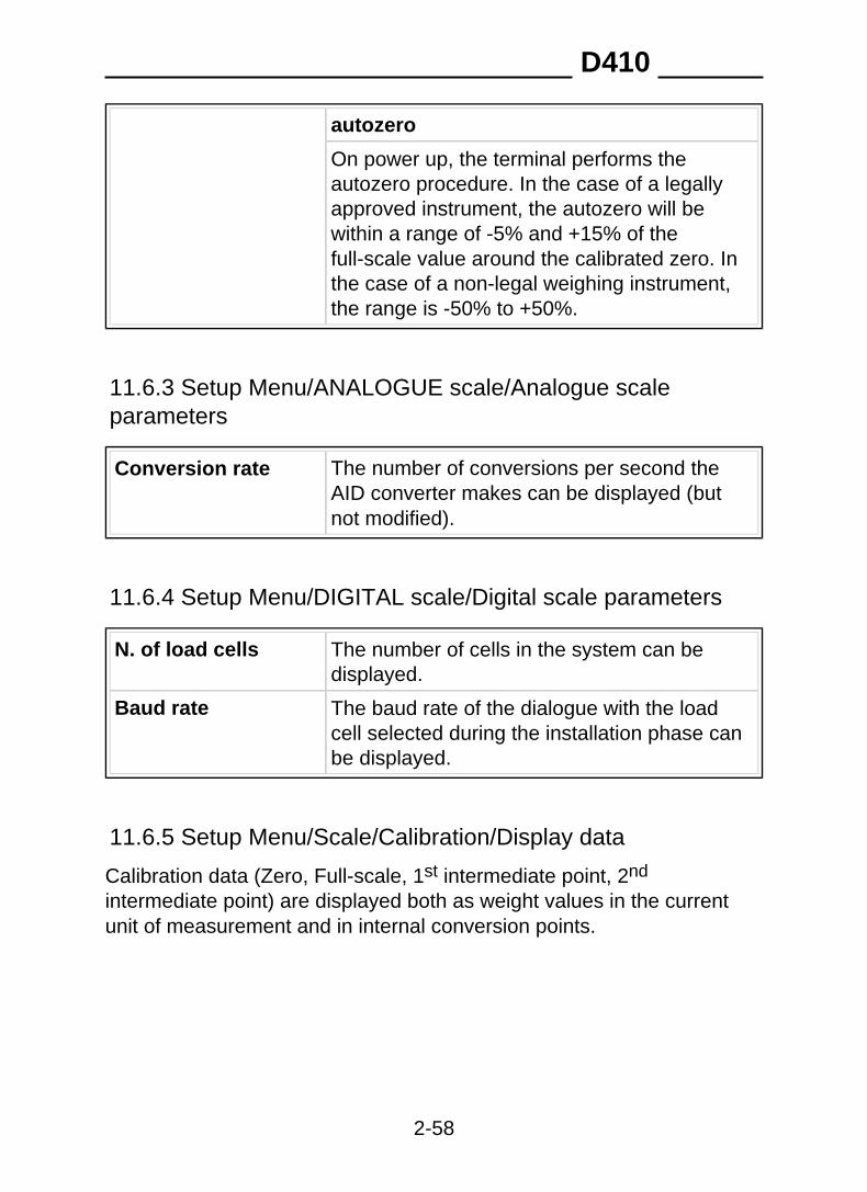
autozero
On power up, the terminal performs theautozero procedure. In the case of a legallyapproved instrument, the autozero will bewithin a range of -5% and +15% of thefull-scale value around the calibrated zero. Inthe case of a non-legal weighing instrument,the range is -50% to +50%.
11.6.3 Setup Menu/ANALOGUE scale/Analogue scaleparameters
Conversion rate The number of conversions per second theAID converter makes can be displayed (butnot modified).
11.6.4 Setup Menu/DIGITAL scale/Digital scale parameters
N. of load cells The number of cells in the system can bedisplayed.
Baud rate The baud rate of the dialogue with the loadcell selected during the installation phase canbe displayed.
11.6.5 Setup Menu/Scale/Calibration/Display data
Calibration data (Zero, Full-scale, 1st intermediate point, 2nd
intermediate point) are displayed both as weight values in the currentunit of measurement and in internal conversion points.
D410
2-58

11.6.6 Setup Menu/Scale/Test
Display points ✔ The number of points in the converter canbe displayed if the scale is the analoguetype.
✔ If the scale is the digital type, the number ofoutput points of each individual scale (scale0-200.000) can be displayed along with thenumber of points of the entire system,obtained by calculating the average of thepoints of all the cells. Each cell is identifiedby a number.
Display weight Displays the weight currently present on thescale. On pressing the High Res. key, thedisplay switches to high resolution for 5seconds. Cyclic transmission of the stringcontaining the weight in high resolution isenabled on Com 2 with the protocol 96008-N-1.
Converter test (*) on inserting the optional accessory board404031, the test 0..20000div. is performed
Temperature (**) The operating temperature is indicatedalongside the identification number of eachcell. The message err. will appear if theoperating temperature is not within the (-40 to+100) °C range.
Power supply (**) The following information is indicatedalongside the identification number of eachcell:
✔ the power supply voltage rating of the cell;✔ the power supply voltage rating of the strain
gauge in the cell.
D410
2-59

The following information is indicatedalongside the identification number of eachcell:
Angular coefficient(**)
✔ the correction made by means of angularcell calibration recorded in the cell;
✔ the same correction recorded in theterminal.
Serial number (**) The following information is indicatedalongside the identification number of eachcell:
✔ the serial number of the cell recorded in thecell itself;
✔ the serial number of the cell recorded in theterminal;
✔ the cell reply address.
This latter is represented by a whole numberbelonging to the (1 to 128) range. However, ifthis reply number is strictly higher than 32, itmeans that the cell is not addressed.
The following information is indicatedalongside the identification number of eachcell:
Program Release(cells) (**)
✔ the software program of the cell;✔ the cell release;✔ the response address of the cell.
(*) Only with analogue cell.(**) Only with digital cell.
D410
2-60

11.6.7 Setup Menu/Personalizations/Operating modes
Terminal language Italian, English, Français, Deutsch,Español, Portugues
The language used during normal operation(may differ from the menu display language)
Decimal separator Point, Comma
Single Weightoperation
Standard, Sum weighing, Unloadingextraction, Loading extraction (see Use of theterminal chapter of the user manual)
Printer see par. 11.6.8 on page 2-63 , par. 11.6.9on page 2-67 , par. 11.6.10 on page 2-68
Automatic printing NO, YES
MPP operation See the Options chapter of the user manualand par. 11.6.11 on page 2-70
Traffic Light See par. 11.6.12 on page 2-71
Connection toexternal processor
This function is to be used in conjunction withthe personalization program supplied by theManufacturer. This program enables you to:
✔ select which of the data managed by theterminal are to be transmitted or printed;
✔ select the position which the data are to beprinted on the printout;
✔ insert characters in any position of theserial transmission string.
D410
2-61
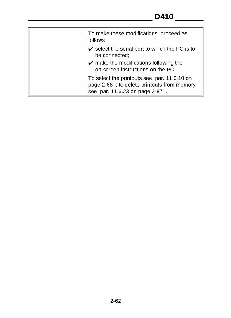
To make these modifications, proceed asfollows
✔ select the serial port to which the PC is tobe connected;
✔ make the modifications following theon-screen instructions on the PC.
To select the printouts see par. 11.6.10 onpage 2-68 ; to delete printouts from memorysee par. 11.6.23 on page 2-87 .
D410
2-62
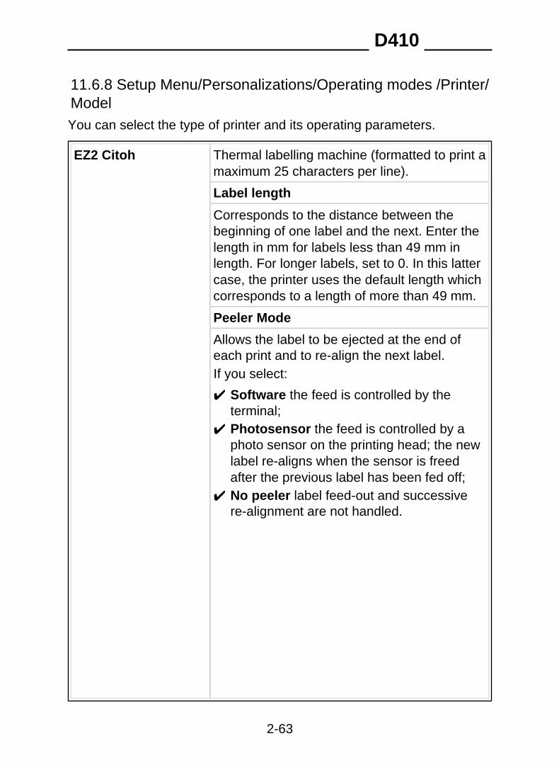
11.6.8 Setup Menu/Personalizations/Operating modes /Printer/ModelYou can select the type of printer and its operating parameters.
EZ2 Citoh Thermal labelling machine (formatted to print amaximum 25 characters per line).
Label length
Corresponds to the distance between thebeginning of one label and the next. Enter thelength in mm for labels less than 49 mm inlength. For longer labels, set to 0. In this lattercase, the printer uses the default length whichcorresponds to a length of more than 49 mm.
Peeler Mode
Allows the label to be ejected at the end ofeach print and to re-align the next label.If you select:
✔ Software the feed is controlled by theterminal;
✔ Photosensor the feed is controlled by aphoto sensor on the printing head; the newlabel re-aligns when the sensor is freedafter the previous label has been fed off;
✔ No peeler label feed-out and successivere-alignment are not handled.
D410
2-63
Extra Feed
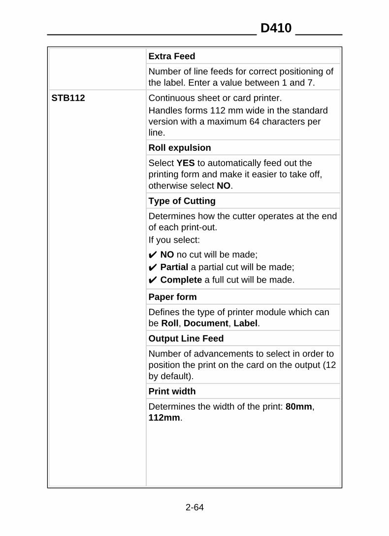
Number of line feeds for correct positioning ofthe label. Enter a value between 1 and 7.
Continuous sheet or card printer.STB112Handles forms 112 mm wide in the standardversion with a maximum 64 characters perline.
Roll expulsion
Select YES to automatically feed out theprinting form and make it easier to take off,otherwise select NO.
Type of Cutting
Determines how the cutter operates at the endof each print-out.If you select:
✔ NO no cut will be made;✔ Partial a partial cut will be made;✔ Complete a full cut will be made.
Paper form
Defines the type of printer module which canbe Roll, Document, Label.
Output Line Feed
Number of advancements to select in order toposition the print on the card on the output (12by default).
Print width
Determines the width of the print: 80mm,112mm.
D410
2-64

Print Manufacturer
Select YES to print the name of themanufacturer of the instrument, otherwiseselect NO.The manufacturer's name can only be printedif the printer is the tape type.
Epson TM295 Multicopy document printer
Document block
Select YES to enable blocking of thedocument on the print plate, otherwise selectNO.
Document expulsion
Select YES to obtain automatic expulsion ofthe document on completion of printing,otherwise select NO.
Line Feed
Number of line feeds to adapt the printout tothe document.
Output Line Feed
Number of advancements to select in order toposition the print on the output.
Epson LX300+ 80-column printer (formatted to print 40characters per line).
Page length
Determines the length of the print page. Enterthe page length in terms of the number oflines. Enter 0 to have the programmed pagehandled by the printer.
Page break: YES, NO
D410
2-65

Type of Format
Defines the type of format handled by theprinter, which can be Single or Continuous.
Output Line Feed
Number of advancements to select in order toposition the print.
DPT282 Thermal printer
Roll expulsion: YES, NO
Advances the page so that it is correctlypositioned for tearing.
TM300 Tape printer
Roll expulsion: YES, NO
Advances the paper so that it is correctlypositioned for tearing.
Activate sensor paper running out
The sensor is installed on the paper feederand senses when the paper is almost finishedby evaluating the diameter of the reel itself.A LED comes on to indicate when the paperhas almost terminated.To enable the sensor select YES, otherwiseselect NO.
Activate sensor for paper out
The sensor is installed on the paper reel guideand senses when there is no more paper.To enable the sensor select YES, otherwiseselect NO.
D410
2-66

Type of Cutting
Establishes the way the cutter operates at theend of each print.If you select:
✔ NO no cut will be made;✔ Partial a partial cut will be made;✔ Complete a full cut will be made.
STB60 Stampante termica
Not yet available.
Neutral Generic printer output.
11.6.9 Setup Menu/Personalizations/Operating modes /Printer/PortIndicates the possibility to configure a serial port for connection of a textmode printer (NO, Com01, Com02).
D410
2-67
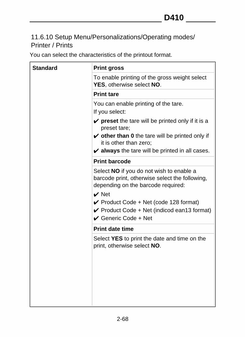
11.6.10 Setup Menu/Personalizations/Operating modes/Printer / PrintsYou can select the characteristics of the printout format.
Print grossStandard
To enable printing of the gross weight selectYES, otherwise select NO.
Print tare
You can enable printing of the tare.If you select:
✔ preset the tare will be printed only if it is apreset tare;
✔ other than 0 the tare will be printed only ifit is other than zero;
✔ always the tare will be printed in all cases.
Print barcode
Select NO if you do not wish to enable abarcode print, otherwise select the following,depending on the barcode required:
✔ Net✔ Product Code + Net (code 128 format)✔ Product Code + Net (indicod ean13 format)✔ Generic Code + Net
Print date time
Select YES to print the date and time on theprint, otherwise select NO.
D410
2-68

N. of copies weight print
Establishes the number of copies to be printedautomatically (only for STB112 and DPT282).Enter a numerical value as explained in theUse of the terminal chapter of the usermanual.
Print logo
Select YESto print the logo, otherwise selectNO.
Personalized Displays and enables the personalized printsand/or strings in the memory.
D410
2-69

11.6.11 Setup Menu/Personalizations/Operating modes/MPPoperationAlso consult the Options chapter of the user manual.
MPP with Printer YES, NO
from keypad, from serial commandWeighing request
Data transmission at end of weighing, from serial command
PC commun. port NO, com01, com02
if you select NO, it will not be possible toenable MPP operation
Memorise tare YES, NO
Type of reply Standard, Terminal number, Serial number
If you select Terminal number you must enterthe numerical value (max. 8 figures) asexplained in the Use of the terminal chapter ofthe user manual.
D410
2-70

11.6.12 Setup Menu/Personalizations/Operating modes/TrafficlightOnce red output01 and green output02 (or vice versa) have beenentered ( par. 11.6.15 on page 2-75 ), the following parameters must beentered in order to manage the semaphore:
Weight variationTraffic light timeout (sec.)
The following conditions may occur:
✔ If no weight variation is entered (weight variation 0), the green lightwill come on when the weighing operation has terminated and willremain on until the measured weight is more than the minimumweight (20 divisions).The red light will be on in all other cases.
✔ If the weight variation entered is different from zero, the green lightwill remain on once the weighing operation has terminated, until theweight on the scale changes in relation to the acquired weight by aquantity lower than the set weight variation. As soon as the weight onthe scale differs from the acquired weight by at least the samequantity as the set weight variation, the green light will go out and thered one will come on.For example, if the acquired weight is 5000 Kg and the set weightvariation is 250 Kg, the green light will go out and the red light willcome on when the weight on the scale reaches 4750 Kg because thevehicle is driving off the scale (or reaches 5250 Kg because a secondvehicle is driving on to the scale).
✔ Neither light is on. You can select a maximum "on" time (traffic lighttimeout) for the red and green lights regardless of the set weightvariation and the status of the operation.
D410
2-71

11.6.13 Setup Menu/Personalizations/Outputs/Serial/Com xy
Com xy string, Bar code reader, not utilised,occupied by printer
string Extended, Cb, Visual, Idea, Cma, Onrequest with address, Extraction,Personalized
terminal number editor
Only for Cma and on Request with address
protocol Cyclic, On request, Ack-Nak, Remotecommands
Configuration For the hardware characteristics of the serialport see par. 11.6.14 on page 2-74
Checksum mode Select YES to enable the checksum mode,otherwise select NO. Can only be set if theselected string is Extended, Cma, Requestwith address or Extraction.Refer to par. 10.4.31 on page 2-28 forgreater details..
Bar code reader Data associated to
Enter the General Datum Number asexplained in the Use of the terminal chapter ofthe user manual.The list of general data with the relativeassociated number is given in par. 11.6.19 onpage 2-80 .
D410
2-72

Code type
✔ Standard CBEnter the check digit as explained in the Useof the terminal chapter of the user manual.
✔ NeutralType of generic code
Configuration
Consult par. 11.6.14 on page 2-74 for thehardware specifications of the serial output.
D410
2-73

11.6.14 Setup Menu / Personalizations / Outputs / Serial /String /.../ Com xy configurationAfter having selected the string type, you access the menu forconfiguration of the hardware characteristics of the serial port, whichcontains the following parameters:
Baud rate 600, 1200, 2400, 4800, 9600, 19200, 38400,57600, 115200
serial line transmission rate
7, 8Number of bits
1, 2Number of stop bits
Parity Even, Odd, None
RS232, RS422, RS485Communicationinterface
Serial com check Hardware, Software, None
Hardware : uses the CTS and RTS signals.The CTS input signal must be set to +12V toenable transmission on the TX pin. Theterminal sets the RTS output to +12V to signalthat it is ready to receive (available on COM1only).Software : transmission of the character<XON>(11H)enables transmission;<XOFF>(13H)suspends transmission.
D410
2-74

11.6.15 Setup Menu/Personalizations/Outputs/Input-Output
status at rest Norm. open (normally open)
Norm. closed (normally closed)
operation (input) Disab. (disabled)
Zero-set scale
Acquire tare
Cancel tare
Acq/Del. tare (acquire/delete tare)
Print weight
Disab. weigh (disables weighing)
Send (executes a transmission)
Disab. settings (disables settings)
Start
In extraction mode (consult the Use of theterminal chapter of the user manual), thishandles the START operation by supplying theOutput 1 (Request) and Output 2 (Slow)output contacts.The same operation can be carried out bypressing START on the display of the terminal.The next START operation is accepted whenthe value entered for Set Point 01 has beenreached or after a STOP request.
D410
2-75

Stop
In extraction mode (consult the Use of theterminal chapter of the user manual), thisforces the cycle itself to end by deactivatingthe Output 1 (Request) and Output 2 (Slow)contacts.The same operation can be carried out bypressing STOP on the display of the terminal.
operation (output) Disab. (disabled)
Set point
Range
Requested
Can only be selected on output 1. It isactivated when a START operation isrequested in extraction mode (consult the Useof the terminal chapter of the user manual)and is deactivated when the value entered forSet Point 01 has been reached.
Slow
Can only be selected on output 2. It isactivated when a START operation isrequested in extraction mode (consult the Useof the terminal chapter of the user manual)and is deactivated when the extracted weightreaches the value obtained by the differencebetween the value set for Set point 01 and thevalue set for Set Point 02.
Print ok
Transmiss. ok (transmission ok)
D410
2-76

Green
This must be entered in order to handle thesemaphore ( par. 11.6.12 on page 2-71 ).
Red
This must be entered in order to handle thesemaphore ( par. 11.6.12 on page 2-71 ).
D410
2-77
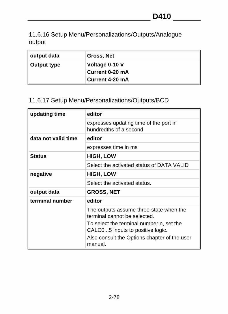
11.6.16 Setup Menu/Personalizations/Outputs/Analogueoutput
output data Gross, Net
Voltage 0-10 VOutput typeCurrent 0-20 mACurrent 4-20 mA
11.6.17 Setup Menu/Personalizations/Outputs/BCD
editorupdating time
expresses updating time of the port inhundredths of a second
data not valid time editor
expresses time in ms
Status HIGH, LOW
Select the activated status of DATA VALID
negative HIGH, LOW
Select the activated status.
output data GROSS, NET
terminal number editor
The outputs assume three-state when theterminal cannot be selected.To select the terminal number n, set theCALC0...5 inputs to positive logic.Also consult the Options chapter of the usermanual.
D410
2-78
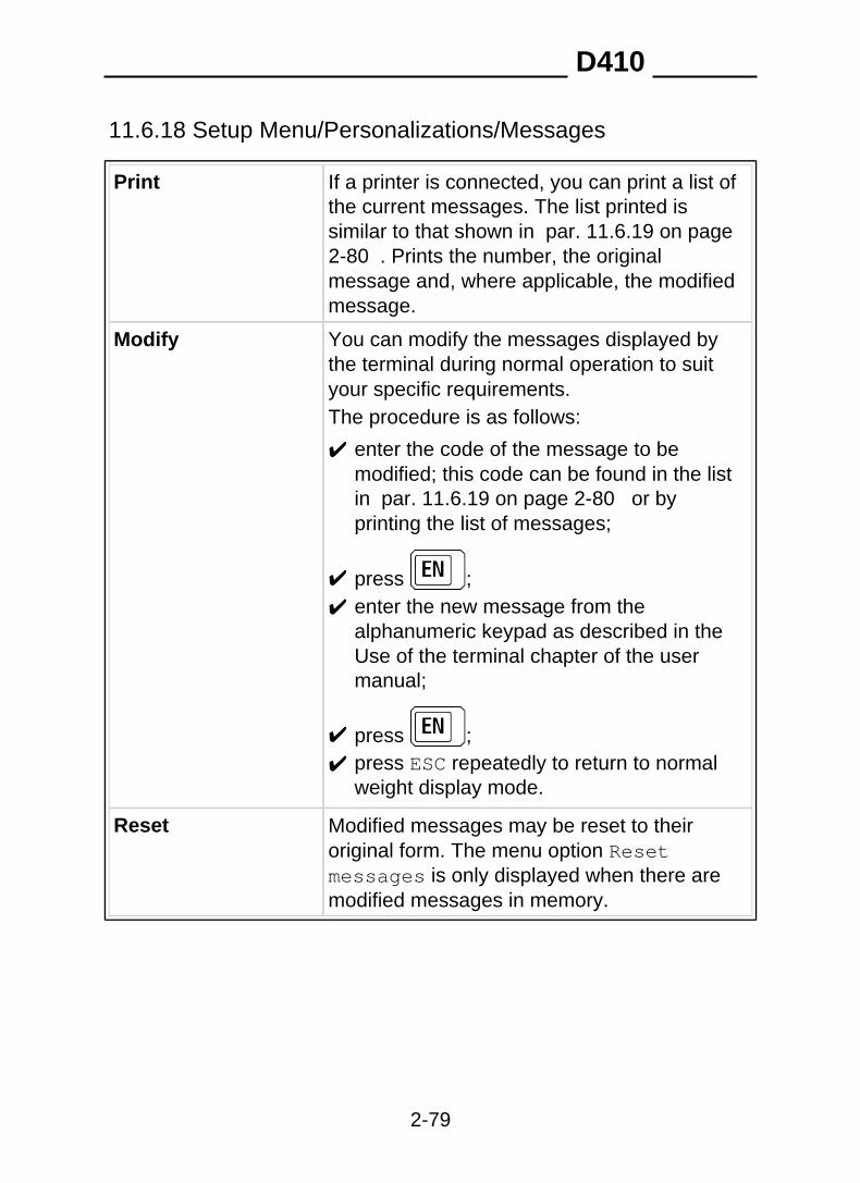
11.6.18 Setup Menu/Personalizations/Messages
Print If a printer is connected, you can print a list ofthe current messages. The list printed issimilar to that shown in par. 11.6.19 on page2-80 . Prints the number, the originalmessage and, where applicable, the modifiedmessage.
You can modify the messages displayed bythe terminal during normal operation to suityour specific requirements.
Modify
The procedure is as follows:
✔ enter the code of the message to bemodified; this code can be found in the listin par. 11.6.19 on page 2-80 or byprinting the list of messages;
✔ press ;✔ enter the new message from the
alphanumeric keypad as described in theUse of the terminal chapter of the usermanual;
✔ press ;✔ press ESC repeatedly to return to normal
weight display mode.
Reset Modified messages may be reset to theiroriginal form. The menu option Resetmessages is only displayed when there aremodified messages in memory.
D410
2-79

11.6.19 List of modifiable messages
General data messages
501 Date General net total512 Time General weighing number523 Extracted Partial gross total534 Partial tare totalGross545 Tare Partial net total556 Net Partial weighing number567 Product net totalStatus578 Tare 1 Product weighing number589 Tare 2 Total net by generic code5910 Disp. range:lower limit Generic code weighing number6011 Tare 1 codeDisp. range: upper limit6112 Tare 1 valueSet point 016213 Tare 2 codeSet point 026314 Tare 2 valueSet point 116415 Text 1Set point 126516 Text 2Set point 136617 Text 3Set point 146718 Set point 21 Text 1 at foot of page6819 Set point 22 Text 2 at foot of page6920 Set point 23 Text 3 at foot of page7021 1.WeightSet point 247122 2.WeightRange 01:lower limit7223 Weighing netRange 01:upper limit7324 Range 02:lower limit Client Code7425 Range 02:upper limit Client descr.7526 Range 11:lower limit Client net total7627 Range 11:upper limit Client weighing total7728 PlateRange 12:lower limit7829 Plate net totalRange 12:upper limit7930 Plate weighing totalRange 13:lower limit8031 Range 13:upper limit RCD8132 Range 14:lower limit RCD Plate8233 Input dateRange 14:upper limit8334 Input timeRange 21:lower limit8435 Input progressiveRange 21:upper limit8536 Input productRange 22:lower limit8637 Description of input productRange 22:upper limit8738 Input clientRange 23:lower limit8839 Description of input clientRange 23:upper limit8940 Input plateRange 24:lower limit9041 Range 24:upper limit RCPD9142 RCPD plateGeneric code9243 Product code RCPD net total9344 Description RCPD weighing total9445 Tare code Recal. 1. weight9546 Tare value Coefficient9647 RoundingConsecutive9748 ResultGeneral gross total9849 OperationGeneral tare total
✔
D410
2-80

Shortcut key messages
219201 PACKSNCONTR220202 DATIME PLATE221203 PROG.NVISUAL222204 OTHERRANGE223205 MEMORYSETPNT224206 REPRINDRANGE225207 CLIENTCODMPP226208 MPP WEIG.R227209 RCDTOTALS228210 PLATEGENTOT229211 RCPDPARTOT230212 PPLATEPROTOT231213 GENTOTGCTOT232214 PARTOTGENC233215 PROTOTPRODC234216 CLTOTTAREC235217 T.RCPDTAR1C236218 PLATETTAR2C237 COEF
✔
D410
2-81

User menu messages
427401 User menu With memory428402 With printerData management429403 DisplayCode management430404 15 mm digitsEntering431405 Reprint 30 mm digits432406 Range Selection433407 ExtractionRange 01434408 Display tareRange 02435409 Range 11 Contrast436410 Totals managementRange 12437411 Range 13 General total438412 Partial totalRange 14439413 Product code totalRange 21440414 Range 22 Generic code total441415 Product code listRange 23442416 Preset tare listRange 24443417 Memory status1st value444418 Client code list2nd value445419 RCD listSet Point446420 Plate listDisplay range447421 Display MPP data RCPD list448422 Preset tare Preset plate list449423 N. of packs Client total450424 Date Time RCPD total451425 MPP operation Preset weight452426 De-activated Plate Total
✔
D410
2-82

11.6.20 Setup Menu/Personalizations/Shortcut keys
Customize shortcutkeys
The quantity and position of the keypadshortcuts assigned to terminal functions canbe modified.
To add shortcut keys to those alreadyselected (up to a maximum of 20) proceed asfollows:
✔ press NEW;✔ position the cursor in correspondence with
the function you wish to assign to ashortcut key;
✔ press SELECT;✔ press ESC repeatedly to return to normal
weight display mode.
The new shortcut key will be added after thepreviously assigned keys.
To change the position of shortcut keysshown on the display, proceed as follows:
✔ position the cursor in correspondence withthe position of the function to be changed ;
✔ press ENTER;✔ position the cursor in correspondence with
the function you wish to assign to thepreviously selected position;
✔ press SELECT;✔ press ESC repeatedly to return to normal
weight display mode.
D410
2-83

This operation causes all the subsequentfunctions to be moved forward by one position.If you enter a function that is already presentin the shortcut key bar, the new position will bemaintained and the old position will becancelled.
To delete a function from the shortcut key,proceed as follows:
✔ position the cursor in correspondence withfunction you wish to delete;
✔ press DEL;✔ press ESC repeatedly to return to normal
weight display mode.
This operation causes all the subsequentfunctions to be moved back by one position.
Customize keyzero-setting
It is possible to reset customized shortcutkeys. The menu option Customize keyzero-setting only appears in the menu ifthere customized shortcut keys in memory.
D410
2-84

11.6.21 Setup Menu/Personalizations/Texts
EditorEntering
You can define two sets of messages, eachcomprising 3 lines of 25 characters, whichmay be inserted at the head or foot of aprintout.
Proceed as follows:
✔ select the set of messages which you wishto insert : In heading or At foot of page;
✔ enter Text 1 from the keypad as describedin the Use of the terminal chapter of theuser manual;
✔ press to confirm;✔ repeat the same procedure to enter Text 2
and Text 3;✔ press ESC repeatedly to return to normal
weight display mode.
Zero-setting It is possible to reset any inserted texts. Theoption Zero-setting only appears in themenu if texts have been inserted.
D410
2-85
11.6.22 Setup Menu/Personalizations/Files
Memory status You can verify how much of the terminalmemory is occupied and, if necessary, recoverused memory. The recovery operation maytake a few minutes. Do not switch off theterminal during this operation otherwise datamay be lost from memory.
Files status Product code, Preset tares, Prod. CodeTotal, Generic Code Total.
The number of files and their functions mayvary according to the operating modeselected. Each of these files can becustomized in order to optimise memory useto suit the type of terminal application. Thecustomizing procedure allows you to vary thesize of each file by defining the number ofelements that it may contain. To customize afile, position the cursor in correspondence withthe file and press SELECT.You can create a new file by selecting Create,delete an existing file by selecting Delete, orchange the size of a file by selecting Resize.To increase the size of the file, selectIncrease and follow the instructions on theterminal display; to decrease the size of a fileselect Reduce.
D410
2-86

When a file exceeds the maximum permittedsize, the terminal will display a warning thatthere is insufficient space available. In thiscase, if you still wish to proceed, you will haveto reduce the size of the other files. Care mustbe taken when reducing the size of a file, asthis could lead to the loss of data. If the sizereduction affects memory areas which containdata , these must first be reset before the filecan be resized.
Zero-setting Product Code, Preset tares, General Total,Partial Total, Prod. Code Total, GenericCode Total, Complete Reset
It is possible to reset the contents of theindividual files or reset the memorycompletely. The latter operation results in theloss of all the data stored in the terminalmemory.
11.6.23 Setup Menu/Personalizations/Prints-Customizedtransmis. memorizedAllows you to delete any customized printouts and/or transmissions fromthe memory (Delete all).
CAUTION This operation permanently deletes customized printoutsfrom memory. To restore them, the terminal must bereconfigured using the program supplied by the Manufacturer(see par. 11.6.7 on page 2-61 ).
D410
2-87
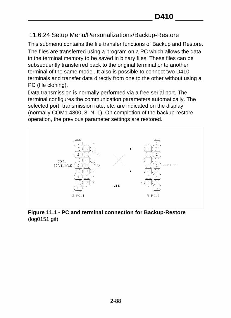
11.6.24 Setup Menu/Personalizations/Backup-RestoreThis submenu contains the file transfer functions of Backup and Restore.The files are transferred using a program on a PC which allows the datain the terminal memory to be saved in binary files. These files can besubsequently transferred back to the original terminal or to anotherterminal of the same model. It also is possible to connect two D410terminals and transfer data directly from one to the other without using aPC (file cloning).Data transmission is normally performed via a free serial port. Theterminal configures the communication parameters automatically. Theselected port, transmission rate, etc. are indicated on the display(normally COM1 4800, 8, N, 1). On completion of the backup-restoreoperation, the previous parameter settings are restored.
Figure 11.1 - PC and terminal connection for Backup-Restore(log0151.gif)
D410
2-88
To transfer files from the terminal to a Personal Computer proceedas follows:
✔ use a communication program that contains the KERMIT transfermode for binary files (e.g. Windows Hyperterminal), and set the samecommunication parameter settings as the terminal;
✔ connect the terminal to the PC using a serial line cable as indicated in Figure 11.1 on page 2-88
✔ if you want to transfer one file at a time, use the Backup function;
select the file to be transferred and confirm by pressing .If you want to transfer all the files select Backup all.
✔ The transfer procedure now starts. Put the PC kermit reception mode.The terminal and the PC will display the name of the file and thepercentage of data transferred.
✔ On completion of the transfer, if the Backup all function was used,press ESC on the terminal to return to normal weight display mode; ifthe Backup function was used, select the next file to be transferred (ifany) and repeat the procedure.
On completion of the operation, the binary files relative to the terminalfiles can be found in the specific directory on the PC, for examplePRODFILE will contain the product file.If there is already a file with this name in the directory, it will not beoverwritten but the new file will be saved with a number appended to thefilename, e.g. PRODFILE1.
D410
2-89

To transfer files from a Personal Computer to the terminal proceedas follows:
✔ go to the directory containing the previously transferred files;✔ connect the terminal to the PC using a serial line cable as previously
described in the Backup procedure;✔ select the Restore function on the terminal; this function allows you
to transfer one file at a time from a PC to the terminal;✔ on the PC, select the Kermit mode send procedure for the file to be
transferred to the terminal;✔ a message will be displayed informing you whether the transmission
was completed successfully.
CAUTION The name of the file to be transferred must the same as thatof the previously received file. Filenames with addednumbers must be renamed.For example, change the name of PRODFILE1 toPRODFILE before transferring it.The management of files on the PC is the responsibility ofthe user.
✔ return to the submenu Restore to transfer further files and repeatthe procedure.
D410
2-90

11.7 Test procedures
To access terminal function tests, press on power up and follow themenu path:
select language>Terminal Tests>select test
11.7.1 Terminal Tests/Serial Ports
✔ Connect the "blind" connector to the ports.The term "blind" connector denotes a connector that connects the inputsto the outputs.For RS232, TX with RX and CTS with RTS.For RS422, TX+ with RX+, TX- with RX-.(See drawings in the Consignment and installation chapter of the usermanual)
11.7.2 Terminal Tests/Inputs-OutputsAs in the serial port tests, you will need to prepare blind connectors thatconnect the inputs directly to the outputs of the same number.For example, connect input 01 with output 01. Refer to the Consignmentand installation chapter and Options chapter of the user manual forthese connections.
11.7.3 Terminal Tests/KeypadFollow the instructions given on the display.
D410
2-91

11.7.4 Terminal Tests/Terminal Configuration ReportIf a printer port has been enabled through the relative menu, the terminalconfiguration report will be printed via this port. If no port has beenenabled, connect a printer and a PC to the COM1 serial port with fixed9600,8,N,1 configuration.The overall setup of the terminal will be transmitted to it.
11.7.5 Terminal Tests/Analogue outputTo calibrate the output voltage, connect a tester with 10V capacity to theterminals. Adjust the output using the keys indicated on the display toobtain a voltage reading between 0 and 10V.To calibrate the output current, proceed in the same way using anammeter.You can also select the Complete calibr. item of the menu tocalibrate both values (current and voltage)..
11.7.6 Terminal Tests/BatteryIndicates the voltage of the internal lithium battery.
D410
2-92
11.8 Repeater scaleThe following paragraphs describe the parameters required to set up therepeater scale Refer to all paragraphs from par. 11.6.7 on page 2-61 to par. 11.6.24 on page 2-88 for the Customizing Menu and par. 11.7on page 2-91 for the Test procedures.
11.8.1 Setup Menu/Repeater scale/Repeater scaleparameters/Serial port/Com xyThe parameters listed below must be entered in an identical way to theones in the main terminal if this latter is to dialogue with the slave.
Baud rate 600, 1200, 2400, 4800, 9600, 19200,38400,57600,115200
7,8Bit number
1,2Stop bit number
Parity Even, Odd, None
RS232, RS422, RS485Communicationinterface
Serial com control Hardware, Software, None
Hardware: the CTS and RTS signals are used.The CTS input signal must be set at +12V toenable transmission on the TX pins. Theterminals sets the RTS output signal at +12Vto signal that it is ready to receive (onlyavailable on COM1).Software: transmission of character<XON>(11H)enable transmission;<XOFF>(13H)suspend transmission.
D410
2-93

11.8.2 Setup Menu/Repeater scale/Repeater scaleparameters/String
Extended See par. 10.2.2 on page 2-11
Comunication
You can select the type of dialogue betweenthe slave and main terminal:
✔ Full-duplex: the communication signalscan be transferred at the same time in bothdirections;
✔ Half-duplex: the signals can flow in onesingle direction at a timer along thetransmission line.
Automatic printing
Select YES to enable the extended string tobe automatically printed, otherwise select NO.
Ranges
The range selected in the installation phasecan be displayed.
Division
This displays the division value (in theselected unit of measurement) entered duringthe installation phase.
Capacity
This displays the capacity value enteredduring the installation phase.
1st range capacity
This displays the 1st range capacity valueentered during the installation phase.
D410
2-94
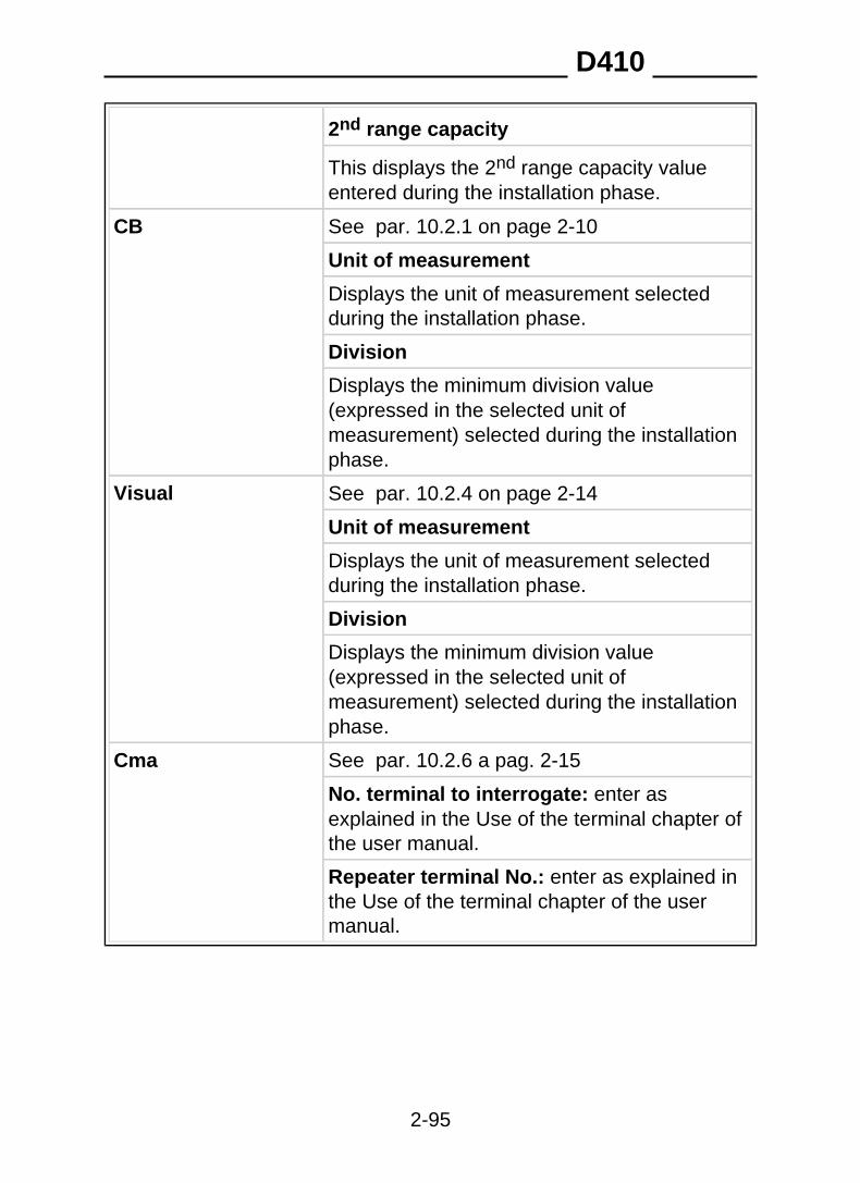
2nd range capacity
This displays the 2nd range capacity valueentered during the installation phase.
CB See par. 10.2.1 on page 2-10
Unit of measurement
Displays the unit of measurement selectedduring the installation phase.
Division
Displays the minimum division value(expressed in the selected unit ofmeasurement) selected during the installationphase.
Visual See par. 10.2.4 on page 2-14
Unit of measurement
Displays the unit of measurement selectedduring the installation phase.
Division
Displays the minimum division value(expressed in the selected unit ofmeasurement) selected during the installationphase.
Cma See par. 10.2.6 a pag. 2-15
No. terminal to interrogate: enter asexplained in the Use of the terminal chapter ofthe user manual.
Repeater terminal No.: enter as explained inthe Use of the terminal chapter of the usermanual.
D410
2-95


SOCIETÀ COOPERATIVA
BILANCIAI
SOC. COOP. BILANCIAI CAMPOGALLIANO A.R.L.41011 Campogalliano (MO) Via Ferrari, 16
tel. +39 (0)59 893 611 - fax +39 (0)59 527 079home page: http://www.coopbilanciai.it
E-mail: [email protected]
service apres-venteservizio post-vendita after sales serviceKundendienstservice servicio post-venta serviço pós-venda
tel. +39 (0)59 893 612 - fax +39 (0)59 527 294