terminal a, low-pressure oil-filled nongraded type
TRANSCRIPT
urements are used to calculate conductor three-fifths full scale; i.e., 150 volts. tion to yield values of excitation voltage.temperatures. The thermal constants The vacuum-tube voltmeter V2 is a peak- These calculated values of cable-excitationneeded in these calculations have been indicating instrument with a calibrated voltages agreed within 4 1.2%. Meas-furnished bythe respective manufacturers. accuracy no worse than ±=2% of full scale; urements were made for nominal excita-
i.e., 150 volts. All meter accuracies were tions of 160, 180, 200, 220, 240, and 260MEASUREMENT OF CABLE-EXCITATION checked by the Cornell Measurements kv, above ground.VOLTAGES Laboratory. Consequently, accuracy of Schedule of Tests and MeasurementsFig. 4 presents a diagram of the circuit the bus voltage determination is limited
used to determine the values of voltage by the accuracy of the voltmeter readings. Tables II and III present a proposedapplied to the cable systems. The stand- Measurements of the divider output schedule of the cable system research andard capacitor C. is known to an accuracy voltages and the induced voltages of test program. It is believed the outlinedof 40.02 ,uf (micromicrofarads); the the high-voltage transformers were made program provides for maximum acceler-measuring capacitor Cm to an accuracy of as a function of the tap settings on ated cable system aging, along with the±25 ujf. The electrostatic voltmeter V1 the main supply transformer. Both optimum sets of test data in the period ofhas a calibrated accuracy of ±41% of sets of voltages were reduced by calcula- time allotted for the research program.
tual designs, each according to the typeerminaLow- ressure of stress imposed in relation to the
dielectric strength under that type of
Oil-FilledNongra ed Type stress, and two designs may rank in oneorder as to a-c breakdown and in thereverse order with respect to impulse.
E. D. EICH L. C. EBEL E. O. JUHLIN The second aspect that must be con-ASSOCIATE MEMBER AIEE ASSOCIATE MEMBER AIEE ASSOCIATE MEMBER AIEE
THE CONVENTIONAL style of termi- have a terminal that does not have annal, either pothead or sealing end, for electric stress greater at any potint than
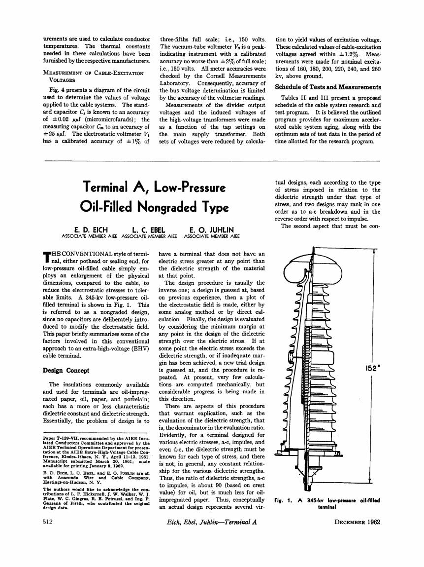
low-pressure oil-filled cable simply em- the dielectric strength of the materialploys an enlargement of the physical at that point.dimensions, compared to the cable, to The design procedure is usually thereduce the electrostatic stresses to toler- inverse one; a design is guessed at, basedable limits. A 345-kv low-pressure oil- on previous experience, then a plot offilled terminal is shown in Fig. 1. This the electrostatic field is made, either byis referred to as a nongraded design, some analog method or by direct cal-since no capacitors are deliberately intro- culation. Finally, the design is evaluatedduced to modify the electrostatic field. by considering the minimun margin atThis paper briefly summarizes some of the any point in the design of the dielectricfactors involved in this conventional strength over the electric stress. If atapproach to an extra-high-voltage (EHV) some point the electric stress exceeds thecable terminal. dielectric strength, or if inadequate mar-
gin has been achieved, a new trial designDesign Concept is guessed at, and the procedure is re- 152"
peated. At present, very few calcula-The insulations commonly available tions are computed mechanically, but
and used for terminals are oil-impreg- considerable progress is being made innated paper, oil, paper, and porcelain; this direction.each has a more or less characteristic There are aspects of this proceduredielectric constant and dielectric strength. that warrant explication, such as theEssentially, the problem of design is to evaluation of the dielectric strength, that
is, the denominator in the evaluation ratio.'D-- r- 9-WI- t-ATM T- Evidently, for a termiinal designed forPaper T-129-VUI, recommended by the AITEE Insu- Evdnty fo emnldsgeo
lated Conductors Committee and approved by the various electric stresses, a-c, impulse, andAaAIEETechnical Operations Department for presen- even d-c, the dielectric strength must be #r,iference, Elmira-Ithaca, N. Y., April 11-13, 1961.- known for each type of stress, and there -.1Manuscript submitted March 20, 21961; made iS not, in general, any costn;rltin
E. D. EICze, L. C. EBEL, and E. 0. JU}LIN are all ship for the various dielectric strengths. < 7with Anaconda Wire and Cable Company, Thus, the ratio of dielectric strengths, a-c n1,Hastings-on-Hudson, N. Y. to impulse, is about 90 (based on crest -
The authors would likce to acknowledge the con-. .tributions of L. F. Hickcernell, J. w. Walkcer, W. J. value) for oil, but iS much less for oil-Plate, W. C. Gingras, R. E. Petruzzi, and Ing. P. impregnated paper. Thus, conceptually Fig. 1. A 345-ky low-presure oil-AledGazzana of Pirelli, wrho contributed the originaldesign data, an actual design represents several vir- terminal
512 Eich, Ebel, Juhlin-Terminal A DECEMBER 1962

sidered is anisotropy of the dielectric that of aluminum. The resultant stress tion of heat to the terminal to facilitatematerials. Porcelain exhibits very little control ring and its immediate dielectric the release of moisture entrapped andanisotropy, oil has none, and oil-impreg- environment was an improvement over adsorbed during the assembly, as in anynated paper has a large amount, all re- the previously used impregnated-paper vacuum impregnation process. However,garding dielectric strengtb. None of the wrapped electrode in two respects. First, heat is not necessary; it is only a time-materials has any significant anisotropy the casting was dielectrically superior be- saving measure.of dielectric constant. Furthermore, the cause: After evacuation, the terminal is filleddielectric strength of all the commnon The encapsulation could be nearly perfect, slowly with degassified oil. Then the de-materials is nonlinear; this is especially obviating the irregularities of paper gassified oil is circulated into the bottomtrue of oil. wrapping of the terminal and out the top usingTo summarize then, in evaluating a The dielectric constant of the encapsulating appropriately installed piping. Circula-
design it is true that one simply compares compound could be made higher than that tion is continued until the gas content isthe dielectric strength to the electric of impregnated paper, thus reducing the reduced to the desired value, as monitoredstress. But the dielectric strength used electric stress by a gage for measuring gas content inmust be exactly appropriate in type of The casting could be thoroughly tested (by oil. In the case of the installation atvoltage, direction of stress, and in dimen- X-ray and corona-level testing) before Cornell, the final equilibrium pressure ofsion. instaation. dissolved gas was less than 20 microns.
Second, shapes could be cast which A basic requirement of such a teminal,Design Details were not possible with paper-wrapped operating as it does at low oil pressure of
constructions; this made it possible to 2 to 20 pounds per square inch gage, isSince the generalized design of a non- have a shape that could be matched that it must be gas-free for correct opera-
graded terminal is familiar, only unusual with hand-applied paper rolls, tape, tion at high voltage. In the assemblydetails will be discussed. etc. procedure described previously, it is im-
perative that no gas be left in the ter-CABLE REINFORCEMENT STRESS CONE CONTOUR minal. This requirement, which appliesThe factory-applied insulation is rein- Various approaches have been used to equally to the cable and joints, fre-
forced in the terminal by the application achieve the desired contour of the stress quently requires extraordinary care.of impregnated paper rolls. The rolls cone, the transition from the cable diam-vary in length, the longest being 50 eter to the stress-control ring diameter. TEST RESULTSinches; this is a practical limit of handling. Some designs employ a paper roll that Eight terminals were installed in 1958 inThey are wrapped from the roll as is pre-cut on one end, and the roll is our laboratory for use in our cyclic agingfurnished onto the cable; this is in con- tightened in place to develop the contour. tests as described in our companion pa-trast to the alternate procedure of apply- Other designs, such as capacitor-graded per.' Exactly the same principles of test-ing the entire roll concentrically and types, use an interleaved foil contour. ing apply; short-time tests can be infor-tightening in place. Our procedure of There is some question as to whether foil- mative, but long-time aging adds informa-wrapping from the stock roll onto the developed contours are suitable for low- tion that no short-time test is able to re-cable required greater skill of the installers pressure oil-filled cable. The Cornell veal.but allowed the designer greater freedom test may help to settle this, since this type Terminals exhibit a voltage condition-since practically any geometry can be of terminal is installed on one end of the ing effect just as cables do; in fact, thebuilt up by this procedure. Properly low-pressure oil-filled cable. terminals require a longer time to reachapplied, wrapped rolls, in contrast with In the present terminal, square-ended stable power factor. The magnitude ofconcentrically tightened rolls, develop paper rolls were wrapped in place and the the conditioning effect is shown in Tablegreater dielectric strengths due to the stress cone contour was achieved by I.greater achievable densities. carving the in-place rolls with a very sharp The terminals were subjected to theTo achieve the required length of rein- knife. Since the rolls were wrapped on voltages outlined in the cyclic aging tests
forcement, rolls are wrapped end to without attempting to form the end at the for the cables, namely, increasing voltageend, the end interfaces are cut into V- same time, high density could be achieved, levels from 345/V3 kv to 500/v/3 kv.shape, and creped paper is used to restore Then an exact contour could, theoreti- At the same time, the terminal carriedthe cylindrical geometry. Thus, the cally, be carved from the bulk of the rolls; currents needed to heat the conductor towrapping technique permitted an almost the accuracy of the contour was depend- the proper aging temperatures, which wasunlimited diameter buildup and an almost ent on the skill of the workman doing the up to 1,400 amperes and yielded a con-unlimited length of reinforcement. carving. Evidently, it is not possible ductor temperature in the cable of 120
to replace an excessively deep cut. degrees centigrade. No attempt was
STRESSsCONTROL RING made to determine the temperature ofThe terminal installed at Cornell em- ASSEMBLY any part of the terminal.
ploys a shaped alumiinum ring cast into Time of assembly varies considerably Power-factor--tress curves were period-an epoxy-based housing as a ground with this style of terminal because of the ically determned on the terminals. Aelectrode. The shape of the ring was skill required. A reasonably experienced length of cable below the stress cone ofoptimized in the electrostatic field cal- crew can complete the assembly of the approximately 2 feet was incEluded as partculation discussed previously. The ring internal parts and set the porcelain in of the terminal for power factor measure-was then vacuum cast in a special epoxy- place in 36 to 48 hours. ments.based compound. Materials were com- After the porcelain is in place and the The power-factor--tress data in Tablepounded for high dielectric constant, high sheath wipe has been made, the terminal II may indicate some deterioration in thedielectric strength, and a thermal co- must be evacuated and impregnated. west terminal of cable KZ and the westefficient of expansion exactly matching The preferredmethod utilizes the applica- terminal of the synthetic cable. We
DECEMBER 1962 Eich, Ebel, Juhlin-Terminal A 513

expected to observe some deterioration Table 1. Voltage Conditioning Effect in EHV Terminalsafter this extended aging at such highvoltages (500/V/3 kv), but as yet we Power Factor in Per Cent
Before Conditioning After Conditioninghave experienced no terminal failures.Cable Terminal At 40 Kv At 200 Kv Diff. At 40 Kv At 200 Kv Diff.
IMPULSE TESTINGU. East...0.233...0.260...... +0.027.....0.291...0.265... -0.026One severe test of a termlnal is the (West.. 0.218. 0.262. +0.044.. 0.237. 0.257. +0.020
impulse testing. Experience has shown K...... East..*.-.0.218......0.244.. +0.026. 0.220. 0.219.. -0.001West...... 0.207... 0.264.... +0.057... 0.211... 0.232.... +0.021that terminal imperfections are rather M.... East. 0.222.0.232. +0.010.0.224 ... 0.221. -0.003
quickly evidenced by these tests. West....0.203... 0.245... +0.042 .... 0.206... 0.214... +0.008Synthetic.......East. 0.094. 0.159. +0.065. 0.094.. 0.108..+.+0.014As outlined in the previous discussion I West....... .0.090. 0.167. +0.077.. 0.093. 0.126. +0.033
on design principles, the over-all electricstrength of the terminal is determined by Table II. Power-Factor-Stres Dta EHV Terminals After Agingthe intensity of the field relative to the di-electric strength at each point. The field Measuring Stress-Power Factor, Per Centpattern is influenced by anything that Cable Terminal At 40 Kv At 120 Kv At 200 Kv At 240 Kv At 290 Kvchanges the dielectric geometry, includ-ing the thickness of insulation and the U.............East ...........0.271. 0.270. 0.265. 0.263. 0.261
W.(...West. 0.245... 0.251... 0.252... 0.253. 0.255conductor diameter. Therefore, it is K .............East. 0.230. 0.231. 0.231. 0.232. 0.232not possible to give a generalized state- M . West. 0.219. 0.266. 0.329. 0. 350. 0.376
M East....0.230... 0.231 .. 0.231 ... 0.232 ... 0.232ment of impulse strength for any terminal (West. 0.223. 0.232. 0.244. 0.248. 0.254without specifying the cable used. Synthetiz.. East. 0.097. 0.097. 0.098.. 20.099. 0.101(West.......0.149.....0.192.....0.215.....0.226.....0.243We used this teriminal with a variety ofcables. Typically, we had failures in therange of 1,400 to 1,550 kv depending onthe cable construction and test schedule ifications to the terminal base to permit paper by Gazzana-Priaroggia et al.2(interspersion of a-c and impulse volt- power factor measurements in the field by We have reviewed the design conceptages). This compared favorably with a insulating the base from the cable sheath, in some detail because we feel that thisstated requirement originally requested and impregnated paper rolls to form the procedure, although it requires extensivefor Cornell terminals of 1,300 kv. The cable reinforcement and stress cone con- development effort, will lead to significanthighest recorded value of impulse with- tour. advances in terminal (and joint) engineer-stand (the cable failed) for this terminal The terminal is of 5-year-old design. ing. In the balance of the paper, wewas 1,750 kv. The Pirelli Company has been supplying have tried to present some aspects of
these terminals for commercial service terminal development not discussed else-Conclusions for 5 years. The epoxy-encapsulation where.
technique was introduced 2 years ago.The terminal we have described was The service record of the terminals References
designed and the mechanical portion adequately confirms the design. There-largely manufactured by Pirelli, S.p.A., in fore, the data are not proferred as com- 1. CABLE No. 4-Low-PaESSUIRE, OIL-FILLED,Milan, Italy. For the installation at plete justification of the design; they S. Ege. AIEE Transactions, see pages 552-58 ofCornell, Anaconda furnished a new con- are given as additional information of this issue.nector to accommodate our 1,700-thou- engineering interest. The original pres- 2. 400 KV Low-PRESSURB, OIL-FILLED CABLE,
P. Gazzana-Priaroggea et al. Paper no. 202,sand-eircular-mil profiled conductor, mod- entation of the design is given in a CIGRE, Paris, France, 1958.
Basic potheads are designed for use oni rressure 'JiI-rilled Capacitor- either high- or low-pressure oil-filledcables. Three of them at Cornell areinstalled on high-pressure oil-filledira ecJ r ot leau s(HPOF) cable and the fourth on low-pressure oil-filled (LPOF). All four are
T. F. BRANDT identical. Terminals, build-ups, baseplates, and other auxiliary parts are pro-vided with each basic pothead to accom-
SAE ARE PROUD, at Ohio Brass manufacture of four 345-ky potheads, modate various types and sizes of cables.V Company, to have a part in the ex- which are presently installed on one end Utilization of series-connected capaci-tra-high-voltage cable test project now in of each of the four cables on test.operation at Cornell University. Sponsor- The basic potheads are of the capacitor- Paper T-129-VflI,reommmimenDdaed by the AIEE Insu-ship is shared jointly by the AEIC graded type. The complete pothead as- AIEE Technical Operations Department for(Association of Edison Illuminating Corn- sembly includes a lower paper roll, or presentation at the rAIBE Extra-High-VoAprltgpany) and EEI (Edison Electric In- build-up, in which the stress cone is 11-13, 1961. Manuscript submitted March 20,stitute). The primary effort at Ohio factory-wound to insure accuracy of loca- 16;md vial o rnigJl 4 91
T. F. BRANDT is with the Ohio Brass Company,Brass was development, design, and tion. Barberton, Ohio.
514 Brandt High-Pressure Oil-Filled Capacitor-Graded Potheads DECEMBER 1962.