termanator design document - massachusetts institute of...
TRANSCRIPT

TermanatorDesign Document
Donald EngRodrigo Ipince
Kevin Luu
Mentoring TA:Brian Schmidt
December 12, 2007

Abstract
This project consists on the design and implementation of a first-person shootinggame with a little twist. The player will be taking the role of the “Termanator,” withthe mission to kill as many creatures as possible. As the game progresses, creatureswill be coming at the player at increasing speeds, incrementing the game’s difficulty.To stay alive, the player must destroy each creature by shooting a constant streamof projectiles. Such stream is controlled by the Termanator through a specializedgun which uses a pointer and a shaker to respectively determine the target and theintensity of the stream. If a creature gets too close to the player, the game is over, andthe score is recorded. Ultimately, the objective of the game is to obtain the highestscore, for the purpose of eternal fame.
The system will consist of four main components: the devices, digital inputs,game engine, and graphics. The inputs are used to generate the power and direc-tion of the stream, so that the game engine is able to calculate the respective gameevents. The game engine will incorporate all the core functionality of the game itselfand generate a structured output for the graphics component, enabling the crea-tures and the stream to be displayed onto the screen.

Contents
1 Overview 4
2 Component Descriptions 82.1 Shaker . . . . . . . . . . . . . . . . . . . . . . . . . . . . . . . . . . . . . . . . . . . . . . . 8
2.1.1 Shaker - mechanical device . . . . . . . . . . . . . . . . . . . . . . . . . . 82.1.2 Pulse Generator . . . . . . . . . . . . . . . . . . . . . . . . . . . . . . . . . . . 92.1.3 Power Calculator . . . . . . . . . . . . . . . . . . . . . . . . . . . . . . . . . . 92.1.4 Power Bar Sprite . . . . . . . . . . . . . . . . . . . . . . . . . . . . . . . . . . . 9
2.2 Video Processing . . . . . . . . . . . . . . . . . . . . . . . . . . . . . . . . . . . . . . . 102.2.1 Camera . . . . . . . . . . . . . . . . . . . . . . . . . . . . . . . . . . . . . . . . . 102.2.2 Clock buffer . . . . . . . . . . . . . . . . . . . . . . . . . . . . . . . . . . . . . . 112.2.3 NTSC to ZBT . . . . . . . . . . . . . . . . . . . . . . . . . . . . . . . . . . . . . 112.2.4 ZBT . . . . . . . . . . . . . . . . . . . . . . . . . . . . . . . . . . . . . . . . . . . . 122.2.5 Video Display . . . . . . . . . . . . . . . . . . . . . . . . . . . . . . . . . . . . . 12
2.3 Pixel Detection . . . . . . . . . . . . . . . . . . . . . . . . . . . . . . . . . . . . . . . . . 122.3.1 Color Space Converter . . . . . . . . . . . . . . . . . . . . . . . . . . . . . . 122.3.2 Frame Filter . . . . . . . . . . . . . . . . . . . . . . . . . . . . . . . . . . . . . . 132.3.3 Pointer Calculator . . . . . . . . . . . . . . . . . . . . . . . . . . . . . . . . . 14
2.4 Game Engine . . . . . . . . . . . . . . . . . . . . . . . . . . . . . . . . . . . . . . . . . . 142.4.1 Creatures . . . . . . . . . . . . . . . . . . . . . . . . . . . . . . . . . . . . . . . . 142.4.2 Projectiles . . . . . . . . . . . . . . . . . . . . . . . . . . . . . . . . . . . . . . . 162.4.3 Game Logic . . . . . . . . . . . . . . . . . . . . . . . . . . . . . . . . . . . . . . 17
2.5 Graphics Block . . . . . . . . . . . . . . . . . . . . . . . . . . . . . . . . . . . . . . . . . 192.5.1 Perspective Transformer . . . . . . . . . . . . . . . . . . . . . . . . . . . . . 192.5.2 Sprites and Sprite Scaling . . . . . . . . . . . . . . . . . . . . . . . . . . . . 212.5.3 Sprite Display Pipeline . . . . . . . . . . . . . . . . . . . . . . . . . . . . . . 21
3 Testing and Debugging 23
4 Conclusion 26
List of Figures
1 Screenshot of Nintendo Wii’s Rayman Raving Rabbid . . . . . . . . . . . . . 42 Screenshot of Termanator. . . . . . . . . . . . . . . . . . . . . . . . . . . . . . . . . . 53 High level organization of Termanator. . . . . . . . . . . . . . . . . . . . . . . . 64 Screenshot of video processing with frame filter shown in green pixels. 75 Block diagram of shaker block. . . . . . . . . . . . . . . . . . . . . . . . . . . . . . 86 Anatomy of the Shaker device. . . . . . . . . . . . . . . . . . . . . . . . . . . . . . . 97 Block diagram of video processing block. . . . . . . . . . . . . . . . . . . . . . . 108 Video input connection to FPGA . . . . . . . . . . . . . . . . . . . . . . . . . . . . 119 Block diagram of creatures module. . . . . . . . . . . . . . . . . . . . . . . . . . . 1510 Block diagram of projectiles module. . . . . . . . . . . . . . . . . . . . . . . . . . 1611 Block diagram of game logic module. . . . . . . . . . . . . . . . . . . . . . . . . . 18
1

12 MATLAB-generated image of projectile perspective. . . . . . . . . . . . . . . 1913 CAD representation of projectiles. . . . . . . . . . . . . . . . . . . . . . . . . . . . 2014 Scale factor, given a specific z (shown in x -axis above). . . . . . . . . . . . . 2015 Representation of pipeline implementation for sprite layering. . . . . . . 2216 Screenshot of XVGA display in HSV. . . . . . . . . . . . . . . . . . . . . . . . . . . 2417 Screenshot of XVGA display, incorporating the pointer detection . . . . 25
List of Tables
1 Table of derivation for iterations . . . . . . . . . . . . . . . . . . . . . . . . . . . . 25
2

Acknowledgements
All accomplishments achieved for this project would not have been possible withoutthe consistent help from the staff and fellow students of 6.111.
First, we would like to thank Professor Terman for his dedication to the class andthe countless amounts of effort he invested into it. From the concepts to demon-strations, his lectures piqued our interest in the subject, and allowed us to let ourimaginations run wild.
Secondly, Gim Hom was phenomenal in the amount of time he spent in the lab.His expertise in digital systems and quickness of thought allowed us to bounce manyideas off of him.
Also, we would like to thank the 6.111 TAs: Alessandro Yamhure, Roberto Carli,and Brian Schmidt. Each and every one of them were extremely helpful in everypossible way, from staying late to give us more working time to enlightening us withtheir experiences of the class.
Finally, big thanks to the rest of the class for many days and nights of fun time.You were a great group of people to work with, and we enjoyed watching the accom-plishments of your projects.
Also, thanks to Danny, Mike, and Timothy.
3
Overview
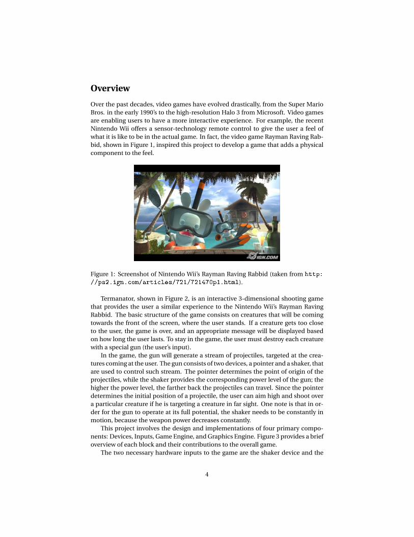
Over the past decades, video games have evolved drastically, from the Super MarioBros. in the early 1990’s to the high-resolution Halo 3 from Microsoft. Video gamesare enabling users to have a more interactive experience. For example, the recentNintendo Wii offers a sensor-technology remote control to give the user a feel ofwhat it is like to be in the actual game. In fact, the video game Rayman Raving Rab-bid, shown in Figure 1, inspired this project to develop a game that adds a physicalcomponent to the feel.
Figure 1: Screenshot of Nintendo Wii’s Rayman Raving Rabbid (taken from http://ps2.ign.com/articles/721/721470p1.html).
Termanator, shown in Figure 2, is an interactive 3-dimensional shooting gamethat provides the user a similar experience to the Nintendo Wii’s Rayman RavingRabbid. The basic structure of the game consists on creatures that will be comingtowards the front of the screen, where the user stands. If a creature gets too closeto the user, the game is over, and an appropriate message will be displayed basedon how long the user lasts. To stay in the game, the user must destroy each creaturewith a special gun (the user’s input).
In the game, the gun will generate a stream of projectiles, targeted at the crea-tures coming at the user. The gun consists of two devices, a pointer and a shaker, thatare used to control such stream. The pointer determines the point of origin of theprojectiles, while the shaker provides the corresponding power level of the gun; thehigher the power level, the farther back the projectiles can travel. Since the pointerdetermines the initial position of a projectile, the user can aim high and shoot overa particular creature if he is targeting a creature in far sight. One note is that in or-der for the gun to operate at its full potential, the shaker needs to be constantly inmotion, because the weapon power decreases constantly.
This project involves the design and implementations of four primary compo-nents: Devices, Inputs, Game Engine, and Graphics Engine. Figure 3 provides a briefoverview of each block and their contributions to the overall game.
The two necessary hardware inputs to the game are the shaker device and the
4

Figure 2: Screenshot of Termanator.
camera. The shaker device is used to determine the power that the user is generatingfor his gun in the game. By the speed that the user is shaking the device at, a powerlevel is sent to the Game Engine, which will use that value to determine how far thestream of projectiles will travel in the z direction. Here, the z -coordinate encodesthe depth in the screen; the higher the z -coordinate of an object, the farther back itis on the screen. If the user stops shaking the device at any given point during thegame, the power level will decrease at a constant rate. This lowers the distance thatthe stream of projectiles will travel and, ultimately, constrains the user from beingable to reach creatures at all. With this input added into the game, a physical aspectis incorporated, giving the user a more unique experience compared to traditionalshooting entertainments.
The camera is used to detect the position of the pointer, which is a green ten-nis ball, held by the user. The position of the pointer in a 1024× 768 XVGA dis-play coordinate system is determined for each frame in the video display. Throughcolor recognition, the pointer is detected by a defined threshold in a particular colorspace. For all pixels that pass the threshold test, the x and y position are accumu-lated, and the position of the pointer is taken to be the center of mass of these pixelpositions. In addition to determining all pixels that pass the threshold test at everyframe, a frame filter, shown in green in Figure 4, is incorporated to eliminate possiblenoises, allowing objects with similar color components to be near the pointer, butnot be detected in the position calculation. After determining the center of mass forthe pointer, a visual representation of the pointer is superimposed onto the game,allowing the user to see where they are aiming during game play.
The Game Engine is responsible for generating all the digital signals needed torepresent the game abstractly. That is, it must be able to determine when the gamestarts, when it ends, and how the game evolves through time. The functionality ofthe component can be broken down into three main parts: creature motion, pro-jectile motion, and game logic. The main task of this component amounts to creat-
5

Figure 3: High level organization of Termanator.
6
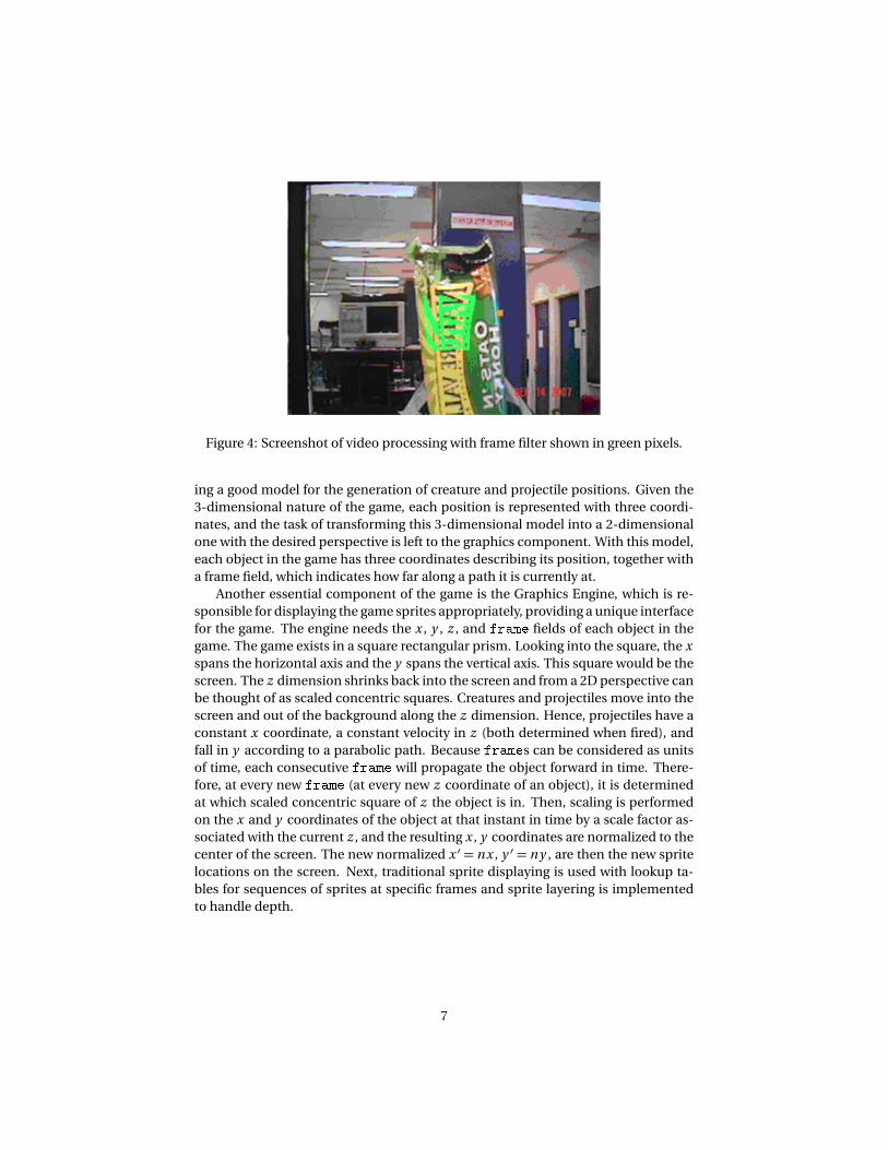
Figure 4: Screenshot of video processing with frame filter shown in green pixels.
ing a good model for the generation of creature and projectile positions. Given the3-dimensional nature of the game, each position is represented with three coordi-nates, and the task of transforming this 3-dimensional model into a 2-dimensionalone with the desired perspective is left to the graphics component. With this model,each object in the game has three coordinates describing its position, together witha frame field, which indicates how far along a path it is currently at.
Another essential component of the game is the Graphics Engine, which is re-sponsible for displaying the game sprites appropriately, providing a unique interfacefor the game. The engine needs the x , y , z , and frame fields of each object in thegame. The game exists in a square rectangular prism. Looking into the square, the xspans the horizontal axis and the y spans the vertical axis. This square would be thescreen. The z dimension shrinks back into the screen and from a 2D perspective canbe thought of as scaled concentric squares. Creatures and projectiles move into thescreen and out of the background along the z dimension. Hence, projectiles have aconstant x coordinate, a constant velocity in z (both determined when fired), andfall in y according to a parabolic path. Because frames can be considered as unitsof time, each consecutive frame will propagate the object forward in time. There-fore, at every new frame (at every new z coordinate of an object), it is determinedat which scaled concentric square of z the object is in. Then, scaling is performedon the x and y coordinates of the object at that instant in time by a scale factor as-sociated with the current z , and the resulting x , y coordinates are normalized to thecenter of the screen. The new normalized x ′ = nx , y ′ = ny , are then the new spritelocations on the screen. Next, traditional sprite displaying is used with lookup ta-bles for sequences of sprites at specific frames and sprite layering is implementedto handle depth.
7

Component Descriptions
Detailed descriptions of each of the four main components of the game are pre-sented in this section.
2.1 Shaker
The Shaker device is used to provide power for the gun to shoot down creaturesin the game. With the game being presented in 3-dimensional space, creatures thatare farther away from the user require more power from the gun to produce a fartherprojectile. In other words, small amount of power limits the gun to reach creatures ofshort distance, while generating much power would allow the user to reach creaturesthat are farther away from the user. Power is generated by the user through howvigorously the user shakes the Shaker device. A slow shake would produce a gun withweak projectile, while a powerful shake gives the user the ability to shoot down morecreatures. Figure 5 describes the general layout of each module that is necessary inthe shaker block.
Figure 5: Block diagram of shaker block.
2.1.1 Shaker - mechanical device
The Shaker is a mechanical device constructed by the team. It consists of a cylindri-cal tube, with a level switch mounted to the bottom (see Figure 6). The Shaker deviceis designed to use a constructed Lego block that presses the level switch when con-tacts are made. The Shaker device is has two leads, one connected to the voltagesignal and another connected to the user input of the FPGA. If the level switch ispressed, connection is made between the voltage signal and the user input, gener-ating a level signal. However, another module, the Pulse Generator, converts thereceived level signal into a pulse. Because of this, the user needs to keep pressingthe level switch to generate pulses which correspond to the power level of the gunin the game.
8

Figure 6: Anatomy of the Shaker device.
2.1.2 Pulse Generator - posedge_detector.v
With the physical shaker device sending level signals, this module is responsible forconverting those signals into pulses. At every positive edge of the clock, the outputsignal is an AND combination between the current signal and the inverse of the lastsignal stored into a register. The result is a signal whose duration is only one clockcycle (1/65Mhz). Once the pulse signal is generated, it will be sent to the powercalculator.
2.1.3 Power Calculator - shaker.v
The power calculator module computes the power value that the Game Engine willuse to determine the z velocity of the projectiles. For every pulse that is receivedfrom the pulse generator, a predetermined value (5) is added to the ongoing sumthat resembles the power value. Additionally, for every fraction of a second, thepower value decrements by 1 to provide the effect that the power dissipates if theuser is not shaking the device during game play. This design is analogous to a sink,where there is a constant rate of drainage, but the water level varies depending onthe rate of water flowing into the sink. Once the power value is determined, it is sentto the Game Engine to be incorporated into the projectiles.
2.1.4 Power Bar Sprite - power_sprite.v
In addition to sending the power value to the Game Engine, the numerical figureis also used for a visual representation of the power level during the game play. Apower bar sprite, whose width corresponding to the power level generated by theuser, is displayed on the upper-left corner of the XVGA display. With a higher powervalue, a longer sprite will be displayed, and vice versa. Since the power value is only8 bits wide, the power bar sprite has a finite width, and will not continue to groweven if the user keeps shaking the device vigorously.
9

2.2 Video Processing
The video processing block is an important component to the project. Its primaryfunction is to take live feed from a camera and identify the presence and location ofa designated marker, which the team decided it to be a green tennis ball, throughcolor detection. Additionally, filtering techniques have been applied to improve therecognition of the marker used as a pointing device. After running the resulting col-lection of pixels through data processing, the output will be coordinate positionsrepresenting the location of the marker on the XVGA display. Figure 7 describes ageneral layout of individual modules and its contribution to the video processingblock.
Figure 7: Block diagram of video processing block.
2.2.1 Camera - video_decorder.v (borrowed from 6.111 website)
The source of the video processing block is a camera based on NTSC-standard, pro-vided courtesy of the 6.111 staff. Conveniently, the FPGA has a built-in compositevideo input port, as pictured in Figure 8. The camera sends input NTSC video datato the RCA phono jack on the right-hand side of the FPGA. From the camera, aninterlaced NTSC signal is received. NTSC, an analog television standard in NorthAmerica and several Asian countries, produces approximately 30 interlaced videoframes per second, a rate sufficient in producing what appears to be a continuousmotion capture for the human eye. The camera outputs an image that is 720 pixelswide and 480 pixels tall, at a clock rate of 60 Hz.
The module responsible for converting camera data into pixels to be displayed
10

Figure 8: Video input connection to FPGA (taken from ://web.mit.edu/6.111/www/f2006/projects/jburnham_Project_Final_Report.pdf).
on the XVGA is the NTSC decoder. This module, originally written by Javier Castro inthe Fall 2005, takes a stream of LLC data from the ADV7185 NTSC/PAL video decoderand generates 24-bits pixels, which are encoded within the stream, in YCrCb format.No modification was made to this particular module.
2.2.2 Clock buffer
The clock buffer block is responsible for synchronizing other blocks that run withdifferent clock rate. With the camera running at 27 Mhz and the XVGA display run-ning at 65 Mhz, the clock buffer centralizes both blocks so that the entire unit isrunning synchronously. This particular block consists of two primary modules: theNTSC to ZBT module and the ZBT module.
2.2.3 NTSC to ZBT - ntsc2zbt.v (modified from 6.111 website)
The basic functionality of this module was constructed by Professor Chuang. Thismodule prepares the NTSC data to be loaded into the ZBT RAM for video display.Some modifications were made to efficiently utilize the fixed dimensions of the ZBTand to improve the resolution of the video images.
The data input is changed from an 8-bit value to 24-bit, representing the 24-bit YCrCb value. Originally, the data input was an 8-bit luminance, used to displaya black and white image. In an effort to produce an image in YCrCb color space,the data input must increase its size to accommodate the two other color compo-nents. Since the output from the NTSC decoder is 30-bit, only the most significant8 bits for each color components are necessary (in this case, ycrcb[29:22] for Y,ycrcb[19:12] for Cr, ycrcb[9:2] for Cb). Ultimately, all three components of
11

this particular color space will be used for color detection.In addition to the change in the storage capacity of data input, the NTSC to ZBT
module down-samples each 8-bit color into 6-bit value, total of 18-bit for the eachpixel. This technique is used to efficiently utilize the space provided by the ZBT.Since each ZBT address is 36 bits long, 2 entries of 18-bit pixels can be stored intoeach address. In the end, the NTSC to ZBT modules output a 36-bit data for 2 pixelentries, along with 19-bit address, to the ZBT memory module.
2.2.4 ZBT - zbt_6111.v (borrowed from 6.111 website)
The ZBT RAM is the memory of choice used in the video processing block. Thismodule is implemented by Professor Chuang as a simple ZBT driver. The ZBT mem-ories have two cycle latencies on read and write, and need a longer data hold timesaround the positive edge of the clock to work properly. The ZBT module takes infive inputs: the system clock, the clock enable for gating ZBT cycles, the write en-able, the 19-bit memory address, and finally, the 36-bit data to write (in this case, 2entries of adjacent pixels). The data to write can be presented and clocked in im-mediately, while the actual writing to RAM will occur two cycles later. Unlike write,read requests are processed immediately, but the read data is not available until twocycles after the initial request. The primary output of this module is the read data,which are the two stored pixels of the current address. For the implementation ofthis project, no modifications have been made to this module.
2.2.5 Video Display - vram_display.v (modified from 6.111 website)
This module is responsible for generating display pixels from reading the ZBT RAM.This module is modified in response to the changes in resolution that is to be dis-played. It is set to have the same corresponding number of bits with the NTSC toZBT module, so that the number of pixels matches correctly.
2.3 Pixel Detection
The output of the camera is in YCrCb, a family of color space that is frequently usedin video and digital photography systems. It utilizes luminance and chrominanceto display its output. By knowing the YCrCb value of the marker that needs to bedetected, it is possible to create filters with derived thresholds, using them to filteronly pixels that correspond to the marker. With this, the center of mass of all pixelsaccumulated can be calculated, and can be used as the designated location of themarker in the game.
2.3.1 Color Space Converter - ycrcb2rgb.v, rgb2hsv.v
There have been some suggestions of working in a different color space, such asRGB, for easier implementation of the color threshold in the filters. When compar-ing the two different color spaces, RGB is a more intuitive standard, where a largerproportion of people are familiar with RGB than YCrCb.
12
With this in mind, an initial module developed by Xilinx is used to convert a30-bit YCrCb value into a 24-bit RGB value. With constants hardcoded into the con-version, this particular module utilizes combination of YCrCb to produce the colorscheme that most people are familiar with.
Much experimenting and testing has been done to detect pixels using the threespecified color spaces. From the results of the team’s trials, it appears that RGBcolor scheme performed poorly. From this, the team generalized that low robust-ness to change in the environment is a primary source of error. Because the RGBcolor space cannot differentiate brightness and color, changes in the lighting of thesurround environment can dramatically impact the accuracy of the color detection.In other words, if the color value of the marker increases or decreases, the bright-ness will simultaneously change as well. Detection using YCrCb color space wouldalleviate this issue, but significant noises are still present in various circumstancesbased on the lighting of the surrounding environment and the angle that the camerais pointed. Testing has shown that certain procedures, such as blurring the cameraso that it is out of focus, or tilting the camera to a particular position, would help ineliminating extraneous noises. Ultimately, using YCrCb color space would limit therobustness of the video processing block.
With this in mind, the team decided to experiment with HSV, which is an attemptto describe perpetual color relationships more accurately than RGB, while remain-ing computationally simple. HSV, representing hue, saturation, and value, describescolors as points in a cylinder, whose central axis range from black on the bottom towhite on the top. Compared to the other two color spaces, HSV offers many advan-tages, but from the testing of the project, HSV is able to eliminate all noises in thebackground that could potentially affect the accuracy of the pointer. All in all, theHSV is the color space of choice in detecting pixels of the pointer.
2.3.2 Frame Filer - pixel_detection.v,frame_filter.v
The objective of the frame filter block is to find pixels corresponding to the colorproperties of the marker and eliminate any possible noises that may affect the cal-culation of the center of mass from these pixels. This particular block consists of twoprimary modules: the pixel_detection.v and frame_filter.v.
The first module, pixel_detection.v, is implemented to detect the marker inthe HSV color space. This detection algorithm searches for pixels that falls within apredefined threshold combining H, S, and V. The threshold is determined throughmultiple trials in an effort to find the optimal value to use in detecting the depictedmarker, the green ball. If a particular pixel fits within the defined threshold of HSV,its value will be replaced with a color value corresponding to white. Otherwise, ablack pixel will be sent.
The second module, frame_filter.v, determines whether the detected pixelfrom the first module falls within the small window that resembles the location ofthe pointer. At the press of a button, the module’s refresh window on the screen willdetect any pixels that match the designated threshold levels for each color compo-nents. This module checks to see if the pixels detected falls within a window whosedimensions are given as inputs to the module. If the pixel is within the window, a
13

signal will be sent to the position calculator module to accumulate the x -positionand y -position of that particular pixel. If the pixel detected is not located within thewindow, it will be discarded. When the entire XVGA screen is finished refreshing,a frame_reset signal will be sent, signaling the position_calculator moduleto compute the average x -position and y -position for the collection of pixels. Thecoordinate of that pixel will be the new center for the next frame filter cycle.
2.3.3 Pointer Calculator - position_calculator.v
At every frame reset, the module will begin accumulating the x -position and y -position of pixels that falls within the refresh window. If a save_pixel signal isreceived from the frame_filter module, this module will accumulate the corre-sponding x -position and y -position. On the other hand, the pointer calculator willdiscard coordinates that belong to pixels outside of the refresh window. Once theframe is completed refreshing, the pointer calculator will compute the average x -position and y -position and send the value as the determined location of the pointeroff to the Game Engine block. At the same time, the same value will be sent back tothe frame_filter block, and that figure will be the new position of the updatedwindow used in the module. Through this procedure, the refresh window will be atthe approximate location of the pointer at the next frame cycle. One assumptionmade here is that the pointer will not be physically moved at a rate faster than theupdate of the frame.
2.4 Game Engine - game_engine.v
The Game Engine block is the primary portion of the game; it is responsible for gen-erating the signals needed to represent the game in an abstract manner. Below aredescriptions of the three major attributes of the engine: the creatures, the projec-tiles, and the game logic.
2.4.1 Creatures - creature.v, creatures.v, rng.v
To simplify the control of the creature movements on the screen, there are only fourallowable paths for the creatures to walk down through. Once a creature starts off ina path, it will stay in the same path, getting closer and closer to the front of the screenas time progresses. Also, to simplify the problem of spawning and destroying crea-tures, a set number of creatures will be used at all times (8). Each of these creaturescan be in an active or inactive mode, which will determine whether they are dis-played on the screen or not. Therefore, simply making these creatures loop aroundthe paths (i.e., relocating each creature to the beginning of the path once it reachesthe end) will achieve the desired effect. To avoid making the game monotonous, ev-ery time a creature reaches the end of the path, the path it will take during its nextiteration will be determined randomly. Figure 9 shows a high level block diagram ofthe creatures component.
Basically, this module maintains information with each creature’s current path,position, and frame (determines how far along the path is the creature at). It also
14

Figure 9: Block diagram of creatures module.
sends out a couple of signals that the game logic module needs. One of them is asignal that goes high whenever a creature is close to the front, and the other one is apulse that indicates when a creatures is restarting on a new path.
This module was implemented by first dealing with a single creature (increature.v),and then constructing many instances of these creatures, having them start evenlyspaced along their paths. Since the creatures are just moving linearly in the z axis, itis quite easy and fast to determine their position. For any creature, its x coordinate(length on the screen, with the origin in the bottom left corner) is completely deter-mined by the path in which it’s in, its y coordinate is always 0, and its z coordinate(depth) is simply a linear function of its frame.
The team chose the z axis to span from 0 to 2047, and after some testing, it wasdetermined that in order for the game to be playable, the creatures needed to moveas slow as one z -unit per frame when starting the game. Thus, it was decided thatthe creature frame should also be able to go from 0 to 2047, and then the z locationwould just be determined by subtracting the frame from 2047. Next, the frame raterange was also calculated after some testing, and it is allowed to go from 1 (at thebeginning of the game) to 15, at which point the creatures are moving so fast that itwould be pratically impossible to beat the game.
These frame rates had to be taken into consideration when generating the othertwo signals that go to the game logic module. These are generated by simply com-paring the z coordinate of the creature with some thresholds. These thresholds haveto be large enough so that they will not be missed when the creatures are moving fastand loop around the paths. Basically, setting a window that is at least as large as thefastest speed a creature can achieve, guarantees that the signal will not be skipped.
Finally, choosing a new path for a creature was done via a random number gen-erator. This was implemented in a very simple way. There are two counters, a large
15

one and a small one, that keep counting indefinitely. The ‘random’ number is thentaken to be one of the bits of the large counter, when indexed by the small one. Ofcourse, this will not exhibit truly random behavior, because both counts are peri-odic, but since the creatures are increasing their speeds, the times at which randomnumbers will be needed will vary, so the ‘randomness’ provided by this method isgood enough for our purposes. Nevertheless, this method was only used for debug-ging purposes. A better and simpler method was used for the actual game. Afterseeing how much the pointer location flickered, we decided to use the lower orderbits of the x and y locations of the pointer to code for the new random number (2bits). This seemed to work out pretty good and the creatures seemed to appear inthe paths in a truly random fashion.
2.4.2 Projectiles - projectile.v, projectiles.v
The projectiles are handled in the same general fashion as the creatures. There isa fixed number of projectiles (16), each of which can be active or inactive at anypoint in time. Again, this module maintains information about each projectile’s po-sition and frame. It also maintains an active or inactive state for each projectile,but it solely depends on whether the projectile has flown too high, too far, or if ithas reached the floor. In other words, this module only concerns itself with projec-tile motion, and knows nothing about game logic. An high level block diagram ofthe projectiles module can be seen in Figure 10. Additionally, in this component,each projectile module takes in all the locations of all the creatures and generatesan output which indicates if the projectile has collided with any creature, and if so,it specifies which creature it was.
Figure 10: Block diagram of projectiles module.
The main difference with the creatures module is that projectiles have more thanfour possible trajectories, so their position is perhaps a bit harder to calculate. First,notice that the x coordinate will always remain the same, since it is assumed that
16

the projectiles only travel in one plane (that which is parallel to the plane spannedby the y and z axes). This x position is determined at the moment of launch, and isgiven by the x location of the pointer. Next, the y component can computed fromthe current frame with a simple kinematics equation:
y = yi ni t i a l +vy f −g f 2
2,
where f corresponds to the projectile frame, yi ni t i a l is determined by the y locationof the pointer at the time of launch, and vy and g are constants that were deter-mined (after a lot of testing) to be 7 and 1, respectively. The same can be done withthe z component, as the projectile travels with constant velocity in this direction.The initial position in the z dimension is always 0, and the speed varies with thepower given.
The trickiest part in this module was getting everything to fit together. First off,some parameters had to be estimated taking playability into consideration, suchas the initial speed in the y direction. Once this was done, the maximum time offlight for a given projectile had to be calculated. With that in mind, it was necessaryto have the frame be able to go high enough to enable to longest trajectory to becompleted in time. The problem was that the more frames needed, the more spacedout the projectiles needed to be. This is not good, because the more spaced out theprojectiles are, the less of a ‘stream’ effect we get, and it turned out that having 32projectiles as initially planned was way too computationally intensive for the restof the game (as the team found out with trial and error), so there was the addedconstraint of the number of projectiles. These issues were resolved by creating asolid testbed that allowed the tweaking of pretty much any parameter that was beingused. After a lot of trial and error, parameters that offered the desired effects werefound.
2.4.3 Game Logic - game_logic.v, get_index.v
This module is responsible for generating all the game event signals and determin-ing how the game evolves. A high level block diagram of this module can be seenin Figure 11. The basic tasks of the game logic module can be summarized as thefollowing.
Game start and pause The game logic modules needs to know when to start thegame, and when to pause it. This is fairly simple to implement. A pulse that in-dicates when the game starts is used to reset all the registers to their initial sta-tus, including those in the creatures and projectiles modules. Next, the pausesignal simply stops the game momentarily when it is high. To achieve this,the condition that the pause signal must be low was added to every alwaysblock in the entire game engine. With no problems, this achieved the desiredfunctionality.
Creature frame rate The creature frame rate must increase as time marches on.Moreover, the game score is dependent on how long the use was able to stay
17

Figure 11: Block diagram of game logic module.
alive. Thus, the game logic module keeps a timer that starts every time a newgame is started, and that only moves whenever the game is not paused. Us-ing this simple timer, the creature frame rate is increased by 1 unit every time16 seconds have elapsed. These numbers were again chosen empirically afterplaying a few games and determining what would be a good level for users tohave fun.
Collisions This is perhaps the most important task of the game logic module, be-cause it is used to determine which creatures and which projectiles will be-come inactive. The collisions bus coming from the projectiles module is usedto determine which projectiles have collided with which creatures. This isdone by passing the bus through an array of get_index.v modules, whichdetermine which creature each projectile has hit. Once this is done, the gamelogic module just compares which of these possible collisions are actuallyvalid, taking into consideration whether the creature and the projectile inquestion are currently active or not.
Game end Determine when the game ends is fairly easy. The game logic modulesimply looks at the close-to-front signal passed in from the creatures module.If any creature that is currently active is too close to the fron of the screen, thenthe game is over.
18

2.5 Graphics Block - graphics03.v
The graphics engine consists of two main components: the perspective transformerand the sprite pipeline. The Game Engine uses a 3D coordinate system to performgame logic, but the display uses a standard 1024× 768 XVGA display, which is ofcourse 2D. The perspective transformer is responsible for making the conversionfrom 3D to 2D to display sprites at the right location. In addition there is a perspec-tive scaling algorithm that will properly scale the sprites according to their depth.The sprite pipeline takes these sprites and displays them in the proper layering ac-cording to their depths. Combining both of these modules is enough to create apseudo 3D perspective representing the current state of the game.
2.5.1 Perspective Transformer - 3Dto2D_transformer.v
Using the sprite’s coordinates in 3D space, the perspective transformer displays thissprite at the correct 2D coordinate on the display. Rather than using a complicatedmatrix calculation a simple “tunnel perspective” is used with a point of origin lo-cated at the center of the screen and the objects radiating out. Depending on asprite’s z coordinate, its x and y will be normalized to the center by a specific factor.At depth 0 no normalization is required, but as z increases the x and y coordinatesof the displayed sprite will pull in closer to the center of the screen. The result ofthis simple normalization is shown in the following plot produced in MATLAB. Eachof the frames in blue represents a different coordinate in z . As illustrated, as z in-creases, the frame is shrinking but renormalized to the screen’s center to producethe desired perspective.
Figure 12: MATLAB-generated image of projectile perspective.
However, the scaling of the z coordinate is not linear. Data collection was per-formed on a sample image from a CAD program to determine at which rate imagesare scaled with increasing z . The image and the data collected are shown below.
19

Figure 13: CAD representation of projectiles.
Figure 14: Scale factor, given a specific z (shown in x -axis above).
From this data the appropriate scaling ratios can be determined. Many methodswere attempted to transfer the scaling relationship displayed in the graph into theGraphics Block. Originally, a polynomial fit was being used. However, the polyno-mial was of degree 4. A degree 2 polynomial was tried but produced undesirableresults as significant deformation was observable. Piecewise linear functions weretried next. The linear approximations that needed to be made were becoming toomany, and as a result linear interpolation was finally decided upon to estimate thescaling factors between data points. Not only is linear interpolation fast, but it pre-serves the original data producing the desired perspective transform.
The linear interpolation algorithm is as follows. Data was collected at some in-terval of z and the scale of z was stored for each interval. The data collected con-tained 17 data points resulting in 16 lines that connect the data. The intervals of zwere such that the range of z was 0-2047. Now for a given input of z the scale fac-tor for this input z can be determined from the linear interpolation of the line thatthis z is located on. The input z has the same range 0-2047. The most significant4 bits were taken from the input z and used in a 4 bit case statement to determinewhich piece of the data set should be interpolated (recall that there are 16 lines thatconnect the data collected). Then the least significant 7 bits of z were used to inter-
20

polate the selected data. The result from the interpolation is then used to scale thex and y coordinate.
The FPGA requires a complicated dividing module if the scale ratios are used di-rectly. An alternative to the dividing module is bit shifting. Hence the scale factorthat is determined by z has a power of 2 maximum. Therefore, x and y can be multi-plied by the scale factor of z and then bit shifted by the power of 2 maximum insteadof divided. The scaled x and y are then normalized to the center of the screen toproduce the ‘concentric’ frames for each z .
2.5.2 Sprites and Sprite Scaling - game_sprites.v
Sprites are stored in the FPGA’s ROM. To generate a new sprite ROM, the *.bmp wasanalyzed by a simple MATLAB program and the RGB fields of the image were con-verted into binary to generate a *.coe file for this *.bmp. The *.coe file was then usedto generate the sprite ROM. The ROM’s width was the number of bits used to de-scribe a pixel’s RGB fields (8 bits for RGB makes a 24bit wide width). The number ofaddresses needed to be a minimum of the number of pixels in the image. Thereforethe addresses needed to be
�
l o g (height×width)�
bits wide. To save space, gamesprites were mapped to a color space. In some instances only 5 colors were neededto describe the sprite, and then only 3 bits of color information needed to be storedfor this sprite. The appropriate colors were then mapped in the verilog code keepingthe ROM relatively small. For example, a sprite image might only contain the follow-ing colors: white, black, brown, red, and transparent. These colors are then mappedas follows: white= 000, black= 001, brown= 010, red= 011, and transparent= 100.
2.5.3 Sprite Display Pipeline - single_pipe_4.v, sprite_pipeline_64.v
The sprite pipeline is used to display the appropriate sprites at the right depth. Itlayers the sprites on top of one another to give the illusion of the 3D game. Thealgorithm for sprite layering depends on z and the sprite’s transparency. For everypixel being displayed, all the sprites are queried for their pixel at that x y location.The sprite pipeline then determines which of these pixels is displayed by the layeringconvention. Pixels are prioritized on their z coordinate and on their transparency.A transparent pixel is always over written. But if two opaque pixels are being com-pared the closest opaque pixel is displayed. There were three pipeline stages and theend result is illustrated in the following diagram.
The above list shows the pixels being pipelined they are each located at the depthwritten on the pixel. The colored pixels are opaque and the white pixels are clear. Inthe first pipeline stage, all 16 pixels are evaluated in 4 groups. The “best” pixel foreach group is contributed into the next stage of the pipeline. In the first group pixel Abegins as the best because it is first. However, pixel 1 overwrites A as best because itis opaque. Pixel 4 is transparent and has not priority. And Pixel 6 is opaque but 1< 6so pixel 1 is considered the best pixel for this grouping of 4 pixels. Pixel 1 is set intothe next stage of the pipeline. The next stage of the pipeline performs the same eval-uation and the very best pixel is then output 3 clocks behind. A simple image shift is
21

Figure 15: Representation of pipeline implementation for sprite layering.
then implemented to shift the entire output back 3 pixels. This is implemented witha sprites’ clock that is jumped 3 edges ahead.
22

Testing and Debugging
To effectively test each and every component of the game, a debugging testbed isneeded for each of the major blocks. The shaker will be displaying the correspond-ing power value that it sends to the Game Engine through the hex display and thewidth of the power bar sprite shown on the XVGA display.
In developing the shaker module, there were several changes to the design to op-timize its performance. Initially, the shaker was designed to determine time differ-ences between consecutive pulses, and that value will be translated into predefinedpower values used by the Game Engine. However, after implementing the physi-cal devices and the module, the device was not working as expected. Occasionally,there appeared to be a sudden drop or spike in the power value, which could lead toother problems in the Game Engine and a flaw in the game. Much time was investedin trying to fix the problem. Through use of the logic analyzer and the oscilloscope,it appeared that, due to mechanical properties, the bouncing of metal contacts ofthe switch in the shaker result in multiple pulses in a very short period of time. Thiswould translate to a sudden increase in power level, which is not physically feasi-ble for the user to produce during the game. After debouncing the shaker’s switch,the problem was not as severe, but not adequate enough to be used in the game.Finally, there have been suggestions to change the design a bit; instead of detect-ing the time difference between consecutive pulses, there should be a ongoing sum.For every pulse that was generated, a defined value was added to the overall powerfigure, while for every fraction of a second, the power value decrements. This isanalogous to a sink, where there is a constant rate of drainage, but the water levelcan remain unchanged if the appropriate rate of water is flowing out of the runningfaucet. Luckily, the implementation of this design turned out to be successful, sothis design was used in the shaker module.
Aside from the shaker, a few changes have been made to the initial design of thevideo processing unit of the project as well. Initially, the pixel detection module wasdesigned to perform all of its detection in YCrCb, a color space that distinguish ob-jects in terms of luminance and chrominance. After implementing the detection inYCrCb, it appears that its performance was decent enough to be used in the game.However, further testing shows that even with the user holding the pointer still, therewas much noise in calculating the center of mass for the pointer, resulting in thepointer sprite “twitching” on the XVGA display. Additionally, the pointer was veryunstable when it was near the edge and side of the screen. After much testing, it wasdecided by the team that detection in YCrCb was not accurate enough to make theproject outstanding. The team hypothesized that this was due to the lack of concen-trated pixels that were detected from the pointer object. Because YCrCb is sensitivetowards curved objects, detection of a ball is not spectacular. Because of this, pixeldetection in HSV was suggested and was implemented shortly afterwards. Researchhas shown that detection in HSV allows more pixels to be detected regardless of theobject’s shape, which would solve the problem that was discussed (See Figure 16).
However, the implementation of the pixel detection in HSV did not offer betterperformance; much noise from surrounding areas was detected in addition to thepointer, resulting in an unstable calculation of the pointer’s center of mass. From
23

Figure 16: Screenshot of XVGA display in HSV.
this, a frame filter design was suggested to be incorporated to refine the pixel de-tection. The frame filter allows only pixels that falls within a designated frame to beincluded in the position calculation. Once the position is determined, that locationwill be used to determine the location of the new frame to be used during the nextclock cycle. This implementation was very helpful to the block because it eliminatesall noises in the surrounding area, allowing the object to be able to move freely toany location within the XVGA display without encountering significant noises.
To further the design of the pixel detection, a problem that can occur during thegame is that the user might lose track of the pointer by moving the object outside ofthe camera’s range. To compensate for this, there have been suggestions to designthe module to detect if the pointer is lost. After much brainstorming, the team de-cided to incorporate a smaller frame into the current frame filter that will be used tosee if a certain percentage of the pixel falls within that frame (See Figure 17).
If there is a high concentration of pixels inside the smaller frame, this impliesthat a device must have a large area of the same color that falls into the definedthreshold, which would be the case of the pointer. Unfortunately, there have beenconsistent bugs in the implementation of this idea; there were many attempts in try-ing to find the optimal percentage to use as a threshold point to determine whetherthe pointer is lost. Due to time constraints for the project, the optimal thresholdpoint was not found, so the implementation of the smaller frame was not includedin the most recent release of the project.
For the Graphics Engine, it was eventually determined that scaling sprites wouldrequire too much computational time, and would have to be abandoned. However,the general algorithm that was used to scale the sprites was rather innovative toavoid performing any divisions. The scale factor for each sprite was determinedby the perspective transformer described above. This scale factor would then de-termine which addresses needed to be read from the ROM. Two sets of registerswere used to assist in this address calculating process. One set represents the last
24

Figure 17: Screenshot of XVGA display, incorporating the pointer detection. Note:the red pixels are used to determine if the pointer is at sight. In this case, the pixelconcentration was not high enough, so the module interprets the pixel as “lost.”
Table 1: Table of derivation for iterationsROM Address 2 3 4 5 7 8 9 12Scaled ROM Address 2 3 4 6 7 8 10 12Spatial Address 1 2 3 4 5 6 7 8ROM / Spatial 2.00 1.50 1.33 1.25 1.40 1.33 1.29 1.50Scaled / Spatial 2.00 1.50 1.33 1.50 1.40 1.33 1.43 1.50Scale Ratio 1.33 1.33 1.33 1.33 1.33 1.33 1.33 1.33
ROM address+1, the other is the last special address (where we physically are on thesprite). Taking this ratio as Scaled/Spatial = R we compare this to the scale factorMax Scale / Scale= S. If R< S then we add extra to the scaled address and carry thisover into our next iteration. This most closely preserves the ratio on each iteration.The iterations which required an update are highlighted below.
This scaling is performed on both the height and width of the sprite in order toproduce the appropriate scaled sprite at a certain scale (which is all determined bythe sprite’s z coordinate). However, during the integration phase it was determinedthat the sprite scaling required too much computational time and would interferewith the camera’s input clock and VRAM access time. In the end the sprite scalingwas abandoned and simple blob scaling was implemented to reduce computationaltime between clock edges.
25

Conclusion
The integration phase of the project proved to be more difficult than expected, andrequired some of the original features of the project to be abandoned. The finalproduct was a less glamorous version of the original, but included fully functionalgame play and interfacing between inputs, game play logic, and graphical display.More details for why the portions of the graphics module were abandoned are ex-plained below.
There were a few in stream modifications made to each of the modules. Origi-nally, the YCrCb color space was being implemented for color detection. However, itwas determined that only the center region of the camera image could be detectedreliably. To create a more robust color detection system, the HSV color space wasimplemented. This accounts for a wider range of lighting conditions. While the HSVcolor space could successfully pick out the colors, it created a large amount of noisein the entire image. Hence, when taking the center of mass on the entire screen, theaverage location was very susceptible to noise.
Another alternative approach was implemented to reduce the average noise cre-ated by HSV. Instead of a median filter to ensure that consecutive pixels were de-tected, a more robust frame filter was implemented to localize the noise. The framefilter is based on the fact that pointer movements are localized to the last frame(i.e. the pointer does not move dramatically between any two consecutive frames).Therefore, we can seed the frame on the location of the last pointer’s average loca-tion using previous estimations.
The game play module had minor modifications. The original plan was to incor-porate 16 creatures and 32 projectile objects. Unfortunately, the compile time for anintegrated project with 16 creatures and 32 sprites pushed upwards of two hours. Inaddition, the processing time was too long per sprite and the camera image sufferedwhen writing and reading to the ZBT. Instead, the creatures and projectiles werehalved. The final project incorporated 8 creatures and 16 projectiles. Compile timewas reduce to approximately 1 hour and the reduced number of creatures and pro-jectiles meant that the graphics module could be reduced from handling 125 spritesdown to handling 64 sprites. Now the three stage pipeline was modified from 125 to25 to 5 to 1 to now 64 to 16 to 4 to 1. This also reduces compilation time with no lossto functionality.
The graphics engine had major modifications in order to compensate for theclock speed. The sprite scaling required too much computational time, and as a re-sult interfered with the camera’s clock either reading from the ZBT or writing. Thiswas an easily identifiable problem because the camera image was a noisy image in-stead of the expected camera image. The noisy image arose directly after the spritescaling was added to the integrated program. To correct this problem a simplersprite was implemented to produce a pseudo-scaling of the sprite blobs accordingto their z axis location. Although this method did not produce the correct perspec-tive scaling, it did produce a sprite scaling sufficient enough to trick the human eye.In addition, the pseudo scaling method was fast enough to not cause any problemswriting to the ZBT or reading from the ZBT.
In the end, the project was a very challenging and rewarding experience. It shows
26

the importance of abstractions at times of integrating different modules of the code.In addition, timing was also a significant issue, and required much time invested toensure that all pieces of the project were able to work together. Aside from the tech-nical experience, this project has taught the team much in communication, timemanagement, and teamwork dynamics. Much was accomplished in the process,and the experience gained will undoubtedly prove invaluable to the team in theirfuture careers.
27