tensile testing - uttar pradesh textile technology institute
TRANSCRIPT
Click on Image to run the animation
TENSILE TESTINGPrinciples of Tensile Testing:
Three ways to carryout tensile test:
1. CRE: Rate of increase of specimen length is uniform with time (the load measuring mechanism moves a negligible distance).
2. CRL: Rate of increase of the load is uniform with time and rate of extension is dependent on the load-elongation characteristicsof the specimen.
3. CRT: Pulling one clamp at a uniform rate and the load is applied through the other clamp. Which moves appreciably to actuatea load measuring mechanism so that the rate of increase of either load or elongation is usually not constant.
CRE V/S CRL:
With CRE principle, maximum load reaches before 3 sec., and rest of the time the specimen remains at higher load (initiallyvery high rate of loading).
For CRL, initial extension was very low and afterwards very high extension with small time (very high extension rate)
So, nature of the curves of same specimen under two different principles will be different.
If specimen length increase in a CRE machine, the rate of loading will decrease.
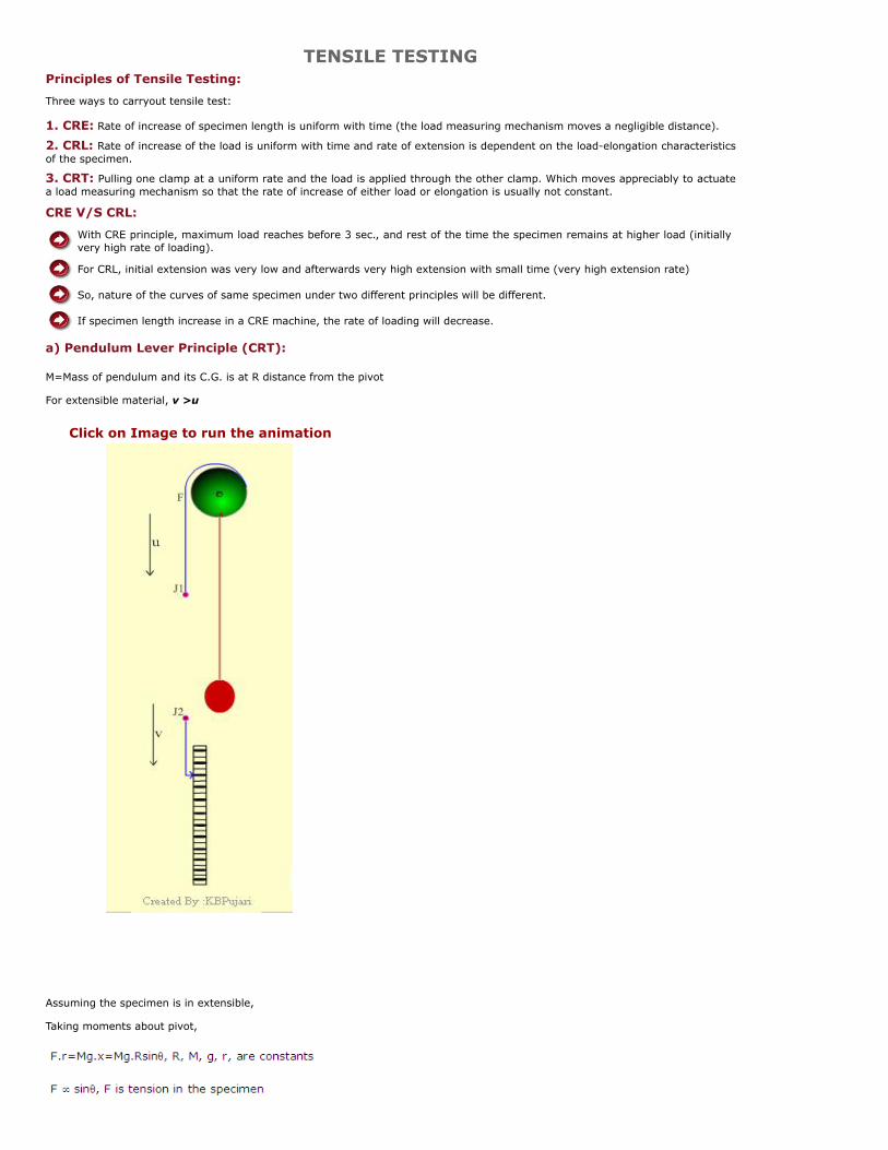
a) Pendulum Lever Principle (CRT):
M=Mass of pendulum and its C.G. is at R distance from the pivot
For extensible material, v >u
Assuming the specimen is in extensible,
Taking moments about pivot,

Machine rate of loading (µ)
Increase in the load per unit increase in the displacement of upper jaw (J1)
The displacement of upper jaw (J1)=rdθ
dF/dθ =(MgR/r)cosθ , dF/ rdθ = µ = (MgR/r2)cosθ
MgR/r2is constant for a particular m/c and known as “standard machine rate of loading” or µ0
Ratio of µ at start and at 450 is (1:0.707), i.e. cos00:cos450
Time rate of loading (L):
Some considerations in Pendulum Principle:
(i) Inertia Effect :
Overthrow at end and at start also (extension without showing any load)
(ii) Effect of specimen extension:
(iii) Scale :
b) Stelometer (CRL):
Capable of measuring strength as well as elongation of fibre bundle.
Works with Pendulum lever principle .
The loading of the specimen is carried out by a pendulum system, which is mounted in such a way that it rotates about itsC.G.
It eliminates the inertia effects associated with normal pendulum principle.
The beam and pendulum start in a vertical position but the C.G. of beam is such that when it is released the whole assemblyrotates.
The speed of rotation is controlled by adjusting the dashpot.


For Extensible Material:

Example– Let extension at breal - 7%
Gauge length -8inch
Breaking load - 220gm
Std. Machine rate of loading, µ0 -1100gm/in
Rate of traverse - 2.28 inch/min
Calculate time of break
T=[{(220/1100) +8 x 0.07}/2.28] x 860 sec
=20sec
c. The beam balance principle:
P x BC = F x AC
The load on the specimen ‘P’ can be varied by changing F, or
by changing the distance from fulcrum,
keeping F constant.
1. Pressley Fibre strength tester:
The beam AB is pivoted at O.

When B rises, the clamp C1 moves upwards.
Initially the beam have a slight inclination of a few degree to the horizontal.
The heavy rolling weight (W) when released from the catch, it rolls down the beam.
A 'O increases until the fibres break.
As soon as the break occurs, the arm AO drops and the brake arrangement stops the carriage instantly.
The distance A'O is the measure of breaking force. The scale is directly graduated on the beam AB.
If we can control the velocity of rolling wt. by a specially made device, we can achieve CRL test condition.
In HVI, this principle is used.
d. Loading by spring (both CRL and CRE):
The instrument is used for single fibre or fine yarns
(i) To test with CRL condition:
Motor M1 runs continuously
As motor M1 starts, the H1 moves upwards at a constant speed.
The spring extends and load is applied on the specimen at a constant rate.
The extension of specimen will cause the leaf spring to touch upper contact C2, which starts themotor M2 and H2 moves down for a short period. This cycle continues until the specimen breaks

G1 and G2 are the sample grips
The upper grip G1 is connected to a leaf spring, which has a restricted movement between theelectrical contacts C1 ad C2.
(ii) To test with CRE condition:
Motor M2 runs continuously
The M1 starts and stops intermittently, as described above.
Used for single fibre and fine yarns.
Recording of Load – Extension (for CRL):
A chart is mounted on a vertical cylinder.
Movement of H1 measures the load, therefore the pen moves vertically along with H1.
The motor M2, which runs only when the specimen extension is being taken up, also rotates the chartcylinder, angular movement of the cylinder being proportional to the extension.
Similar for CRE
e. Inclined plane principle ( CRL):
Click on Image to run the animation

So, CRL condition is achieved.
Extension of the specimen will not affect the rate of loading, the carriage merely rolling further down the plane.
f. Ballistic or impact principle:
Measures ‘work of rupture’ of a specimen instead of max. breaking force.
Potential energy at point 1, W x h1.
When pendulum is released, it swings downward and when it is nearly vertical, it begins topull on the specimen (at 2)
Breaks the specimen and rises to position 3.
Work of rupture = W (h1 – h2) in lbs
‘K’ is known as centre of percussion of the pendulum. it is a point on the axis of pendulumwhere a force may be applied without causing a reaction about the fulcrum.
Click on Image to run the animation

g. Strain gauge principle (Load Transducer):
Most of the modern tensile testers work on this principle.
When the beam bends the length of upper face (AB) increases and lower face (CD) decreases and (NL) remainsunchanged.
Resistance wire (R) cemented on AB also expand and thus the value of resistance changes.
Convert this value of change in resistance to load value (applied on specimen)
Two resistance wires are placed on upper and other two are on lower surface. (To form a Wheatstone Bridge).
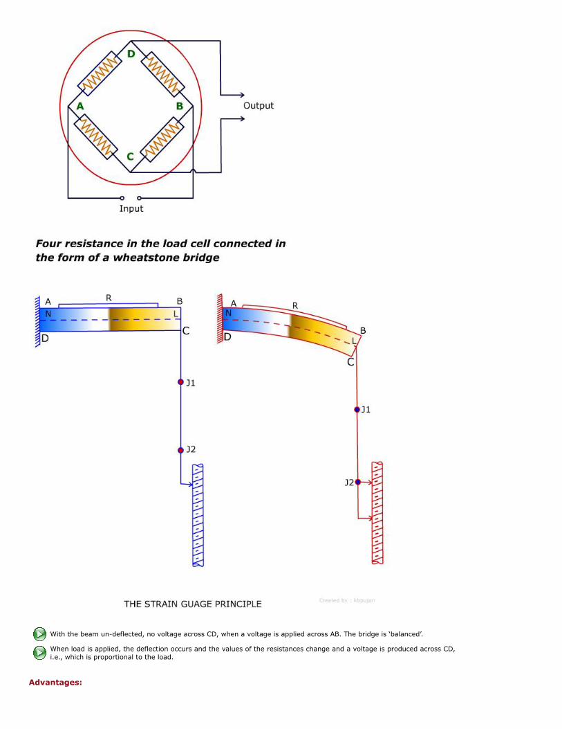
With the beam un-deflected, no voltage across CD, when a voltage is applied across AB. The bridge is ‘balanced’.
When load is applied, the deflection occurs and the values of the resistances change and a voltage is produced across CD,i.e., which is proportional to the load.
Advantages:

Free from inertia errors and friction.
The deflection of the end of the beam is very small, and thus it is tests under ‘CRE’ condition.
Versatility in the type of instrument (yarn, fibre, fabrics, wide speed and load range, etc.)
Disadvantages:
Expert technician is required for maintenance and repair.
Chances of ‘drift’ in electronic circuits.
High initial cost.
Instron tensile tester, UTM, Tensorapid, Zwick, Statimat and various other modern tensile testing instruments work in this principle.
h. Constant tension winding tests:
It provides conditions somewhat similar to actual processing of yarn during winding, warping, sizing etc.
The test is closer to actual running condition.
A, B fixed pulleys and P movable pulley
Under static conditions the tension of the loop will be 0.5L (uniform throughout the loop)
The tension imposed on the yarn will cause it to stretch. “e” be the extension per unit length, v = u (1 + e)
Necessary means are required to adjust the input and output velocity.
The tension required to get the std. breakage rate
Breakage rate and applied tension.
Experimental data shows that
n1 = Breaks/1000 yard
At t1 tension imposed on the yarn will cause it to stretch “e” be the extension per unit length,
v = u (1 + e)
Necessary means are required to adjust the input and output velocity.
Standard breakage rate is “8 breaks per 1000yard of yarn”.
The tension required to get the standard break rate.

Breakage rate, applied tension and single thread strength:
Experimental data shows that
Breakage rate, applied tension and single thread strength:
Single thread strength:
Empirical equation
Dynamic mode T = Tension required to produce “n” breaks/1000yard
Static mode = Mean single yearn strength
σ = S. D. of single yarn strength.
Factor ‘K’ depends on “n” and also change with test length of single thread tensile test.
In B.S. Handbook, the 1st estimate of tension required to produce 8 breaks/1000 yard is,
K = 3.3., with 20” test length and 8 breaks/1000 yard.
Application of constant – tension winding test:

Results obtained may serve as a guide to the behaviour of yarn in subsequent processing i.e. forecast of probable end-breakage rates.
- Comparison of yarn quality
Yarn A Yarn B Yarn C
Count 60.2 61.0 60.8
CSP 2255 2170 2216
Single Yarn Strength 150.5 147.3 148.5
Breaks/1000 yard 18.6 6.8 21.5
YARN STRENGTH:
(i) Single yarn strength:
Instron, Uster etc. 500mm gauge length and speed adjusted so that the time to break is 20 ± 3sec.
(ii) Skein Method (Lea Strength):
Advantages:
It tests a long length of yarn in one test.
Yarn is expected to break at its weak spots, so give more realistic strength values.
Same hank can be used to measure yarn count.
Disadvantages:
Result depends on friction between yarn and also between yarn and hook.
No measure of strength variability.
FABRIC TENSILE STRENGTH
Fabric tensile strength depends upon
Raw material.
Yarn strength (twist: more twist for more strength)
Fabric construction (weave: plane weave is stronger than floats-satin, sateen which are weaker,Density: low density cause weave slippage which result in seam slippage).
Finish applied (resin finish improves weave slippage).
Adverse of “finishing” process.
Measurement of fabric tensile strength
1. Strip Test: (British) BS 2576:
In this method a fabric strip is extended to its breaking point by a suitable mechanicalmeans which can record the breaking load and extension.
Five fabric samples both in warp and weft direction are prepared with each not containingthe same longitudinal threads.
Samples are prepared 60mm x 300mm and then frayed to get 50mm wide specimen.
The rate of extension is set to 50mm/min and gauge length is 200mm. pretension is 1% ofthe probable breaking load.
Click on Image to run the animation-1

Any breaks that occur within 5mm of the jaws or at loads substantially less than the averageshould be rejected.
The mean breaking force and mean extension % of initial length are reported.
Samples are cut (60mm x 300mm) parallel to warp/weft.
Frayed the threads from both sides of the width to bring down to 50mm wide.
For heavily milled fabrics, no fraying is done (50mm x 300mm).
2. Grab Test: (U.S) ASTM D1682:
The grab test uses jaw faces which are considerably narrower than the fabric, so avoidingthe need to fray the fabric to width and hence making it a simpler and quicker test to carryout.
The sample used is 100mm x 150mm jaws are 25mm square which stress only the central25mm of the fabric.
A line is drawn 37.5mm from the edge of fabric to assist it in clamping so the same set ofthreads are clamped in both jaws.
The gauge length is 75mm and speed is adjusted so that the sample is broken in 20±3s.

In this test, there is a certain amount of assistance from yarns adjacent to the centralstressed area so that the strength measured is higher than for a 25mm frayed strip test.
Fundamentally different from strip test.
Jaw faces are considerably narrower than fabric. No need to fray the fabric.
Simpler and quicker method.
3. USTER TENSORAPID (CRE Principle):
For tensile testing of single and ply yarn.
Testing of slivers, leas and fabrics is also possible.
Force measurements up to 1000N without exchanging the force transducer.
The clamping force, the yarn tensioners and the suction-off of the yarn can be programmed.
All numerical and graphical results are displayed on a video screen. (Histogram, L-E curve, tables, etc.)
Package creel for the automatic measurement up to 20 packages.
Calling-up of test parameters of frequently tested yarn types from the memory (up to 40).
Pneumatically-actuated yarn clamps ; the clamp pressure is programmable.
Electronic elongation measurement.
Test speed – Continuously adjustable between 50 and 5000mm/min.
Test length.
----> With horizontal position of clamps, continuously adjustable between 200 and 1000mm.
----> With vertical position of clamps, continuously adjustable between 100 and 1000mm.
Self test - Automatic calibration check for accuracy through inspection.