tensile mechanical properties and failure behaviors of
TRANSCRIPT

Chapter 13
Tensile Mechanical Properties and Failure Behaviors ofFriction Stir Processing (FSP) Modified Mg-Al-Zn andDual-Phase Mg-Li-Al-Zn Alloys
Chung-Wei Yang
Additional information is available at the end of the chapter
http://dx.doi.org/10.5772/54313
1. Introduction
With the gradually depletion of natural resources, especially for the petrochemical fuel inthe Earth, and the global warming problems, the energy-saving, increasing fuel-efficiencyand eco-technologies have become worldwide interested subjects of nowadays. Recently, al‐ternative green energies, such as solar energy/cells, fuel cells, Li-ion batteries, biomass fueland algae fuel, have been developed and used as eco-friendly energies. In addition, materi‐als choosen to give high performance in use with minimized impact to the environment dur‐ing manufacture and delivery is another important concept to take into consideration. Forthe purpose of reducing fuel consumption, therefore, lightweight metallic materials are gen‐erally applied to replace traditional ferrous structural metals in the transportation vehicles
The definition of “Light metals” has typically been given to metallic materials with whichdensity less than 4.5 g cm-3. On this basis, the alkali metals for lithium (Li, 0.54 g cm-3), so‐dium (Na, 0.97 g cm-3), potassium (K, 0.86 g cm-3), rubidium (Rb, 1.53 g cm-3), cesium (Cs, 1.9g cm-3), and alkaline earth metals for berylium (Be, 1.85 g cm-3), magnesium (Mg, 1.74 gcm-3), calcium (Ca, 1.55 g cm-3), strontium (Sr, 2.63 g cm-3), barium (Ba, 3.51 g cm-3) can bethought of light metals. In addition, the core group of metals, such as aluminum (Al, 2.7 gcm-3) and titanium (Ti, 4.5 g cm-3), are also classed as light metals. Considering for the engi‐neering applications of these metals in structural components, Mg, Al, Ti metals and theiralloys are the generally recognized as light metals in inductrial applications with respect toother engineering alloys because the specific strength (i.e., a strength-to-density ratio) is animportant factor to be concerned with the weight reduction. The advantages of decreaseddensity become important in engineering design when mechanical properties of stiffness
© 2013 Yang; licensee InTech. This is an open access article distributed under the terms of the CreativeCommons Attribution License (http://creativecommons.org/licenses/by/3.0), which permits unrestricted use,distribution, and reproduction in any medium, provided the original work is properly cited.

and resistance to buckling are involved. Comparative stiffness for equal weights of a similarbeam increase in the ratios 1:2.9:8.2:18.9 for steel, Ti, Al and Mg, respectively.
Lightweight magnesium (Mg), which has the lowest density (1.74 g cm-3) of any metallicconstructional material in inductrial applications [1,2]. It has many advantages such as highspecific strength, high specific stiffness, well recyclability and radiation absorption of elec‐tromagnetic waves. It also provides high damping capacities, high thermal and electricalconductivities [1,3]. These effects combine to make Mg alloy be an efficient heat sink withgood noise and vibration reduction properties. Researches and developments of Mg and itsalloys are expanded during the past decade. They are now widely used in consumer elec‐tronic industries, biomedical and sports applications. There are numerous applications with‐in the automobiles and aerospace [4,5] of nowadays for the purpose of reducing vehicleweight and fuel consumption [1,6,7]. However, the more widespread commercial applica‐tions of Mg alloys are limited due to its poor formability at room temperature arising fromits hexagonal close-packed (hcp) crystal structure. Therefore, it is important to develop theMg alloys having excellent mechanical properties, especially for applications at elevatedtemperatures. Additionally, the welded structure is inevitably used in the engineering appli‐cation of wrought Mg alloys. The welding of Mg alloys can be achieved by using TIG, MIG,resistance spot welding (RSW), laser beam welding [8,9] and vacuum electron beam weld‐ing [10] processes. But the Mg-based alloys are generally of poor weldability because of theirexceptional thermal and electrical properties and oxidation characteristics. In 1991, a novelfriction stir welding (FSW) process was invented by The Welding Institute (TWI) of UK [11].FSW is a solid-state joining technique and the joining temperature is lower then that in themelting welding process. It uses a high speed rotating tool consisting of a pin and toolshoulder to apply frictional heat and severe plastic deformation of the base metal and toproduce a reliable metallurgical joint. Compared with the traditional melting welding tech‐niques, FSW has many advantages [12-14] and it is quite suitable for the welding of Mg al‐loys and other lightweight aluminum (Al) and titanium (Ti) alloys [15-19]. In recent years,numbers of researches have been conducted to evaluate the feasibility of FSW process forMg aloys. Moreover, the joining of dissimilar metals of Mg, Al, Cu and Ti can also be easilyachieved by the FSW process [20-24].
The present chapter focuses on investigating the modification effect of friction stir process(FSP) on the tensile mechanical properties and failure behaviors of Mg-Al-Zn (AZ-series)and Mg-Li-Al-Zn and LAZ-series alloys. Section 2 will give a overview for the recently re‐searches and applications of the these Mg-based alloys and the FSW-joining/FSP-modifica‐tion techniques. In section 3, extruded Mg-6Al-1Zn (AZ61) alloys with full-annealed (AZ61-O) and FSP-modified (AZ61-FSP) specimens were used for evaluating the strain rate andtexture effects on the tensile properties and failure behaviors. In section 4, we focused on in‐vestigating tensile mechanical properties and failure behaviors of the α/β-dual-phaseMg-10Li-2Al-1Zn (LAZ1021) extruded alloy. A significant ductile-to-brittle transition phe‐nomenon was confirmed for the dual-phase Mg-Li alloy. Since the phase composition andcrystallographic structure vary significantly according to Li content, it is important to inves‐tigate the mechanical properties, as well as deformation and failure behaviors of Mg-Li al‐
Materials Science - Advanced Topics304

loys with performing the FSP modification. The aim in section 5 also focuses on improvingtensile mechanical properties and evaluating failure behaviors of compositional-stabilizeddual-phase LAZ1021 extruded alloy through the modification of FSP technique.
2. Overview of magnesium-based alloys and friction stir process
2.1. Lightweight magnesium (Mg) alloys
Mg alloys can generally be divided into casting alloys and wrought alloys. The casting Mgalloys include die casting, sand casting and thixomolding alloys, and wrought Mg alloys areavailable as bars, forgings, extrusion sheets and plates. Because of the difficulty of coldworking Mg alloys, the castings are more prevalent product (account for about 85-90%) ofMg alloys usage than wrought products. Die casting is one of the most effective fabricationmethods and has been extensively used to produce Mg components. Mg alloys are designat‐ed by a combination of two capital letters followed by two numbers. The first two letters in‐dicate the two major alloying elements in the alloy. The following two numbers stand forthe approximate amounts (in weight percentage, wt.%) for the first and second alloying ele‐ments, respectively. The Mg alloy designation of alloying elements is indicated according tothe following code: A-aluminum, B-bismuch, C-copper, D-cadmium, E-rare earth elements,F-iron, H-thorium, K-zirconium, L-lithium, M-manganese, N-nickel, P-lead, Q-silver, R-chromium, S-silicon, T-tin, W-yttrium, Y-antimony and Z-zinc. For example, the alloyAZ91contains approximately 9 wt.% Al and 1 wt.% Zn. The present section will give anoverview of the generally used Mg-Al based, Mg-Zn based alloys, Mg-Li based alloys andrare earth elements (RE)-containing Mg alloys. In addition, topics of Mg alloys applied asorthopaedic, dental implants and surface treating methods for corrosion resistance are alsointroduced in the end of this section.
2.1.1. Mg-Al based alloys
The Mg-Al alloy system are the most popularly used Mg alloys. Aluminum (Al) is alloyedwith Mg because it increases strength, castability and corrosion resistance. The addition ofAl also provides solid solution strengthening by increasing the critical resolved shear stressfor slip along the basal planes of Mg-Al alloys. Fig. 1(a) shows the equilibrium phase dia‐gram of a binary Mg-Al alloy system. Since Al has a maximum solubility in Mg of 12.7 wt.%at 437°C and its solubility decreases to about 2 wt.% at room temperature, it is expected thatthis system can be strengthened by precipitation hardening when the addition of Al inamount greater than 6 wt.%. However, a coarse, incoherent precipitate of the γ-Mg17Al12
phase intermetallic compound that discontinuously precipitated around grain boundarieswithout the formation of GP zones or intermediate metastable phase [25]. Since Mg alloysundergo creep mainly through the grain boundary sliding (GBS), the γ-Mg17Al12 phase,which has a melting point of about 460°C, can not serve to pin grain boundaries at elevatedtemperatures, and then the creep resistance of Mg-Al alloys is reduced.
Tensile Mechanical Properties and Failure Behaviors of Friction Stir Processing (FSP)…http://dx.doi.org/10.5772/54313
305

(a) (b) (AZ91)
Figure 1. (a) Mg-Al equilibrium phase diagram, and (b) castability of the Mg-Al-Zn alloy system [26].
Zinc (Zn) is the second most important alloying elements, and the Mg-Al-Zn alloys sys‐tem, which is known as the AZ-series, is the one most widely used for castings. General‐ly, Mg alloys are limited to a total Al and Zn content of less than 10 wt.% (the narrowregion in Fig. 1(b) [26]) for obtaining good castability and weldability, whereas the hotcracking is occurred and the ductility of Mg is significantly reduced with the formationof γ-phase Mg17Al12. The castable domain of high-Zn content Mg alloys is obtained withcontrolling suitable Al content and the Zn/Al ratio, as shown in Fig. 1(b). When Zn isadded to the Al-containing Mg alloys, it can help to refine the precipitates. It increasesthe strength by a combination of solid solution strengthening and precipitation harden‐ing because Zn is approximately three times more effective than Al in increasing theyield strength for alloys that are in the solution treated and quenched condition. Zn alsoassists to overcome the harmful corrosive effect of iron (Fe) and nickel (Ni). For the cast‐ing Mg alloys, AZ91D is the most widely used die casting Mg alloy, and other common‐ly used alloys of this type are AZ81 and AZ63 alloys. AZ91D alloy offers a good roomtemperature mechanical properties, corrosion resistance and die castibility, however, it isunsuitable for use at temperatures higher than 120°C due to its poor creep resistance.The Mg-Al and Mg-Al-Zn alloys with the addition of manganese (Mn) element areknown as the AM-series alloys, such as AM60B and AM50A. They display better ductili‐ty and fracture resistant property than AZ91 alloy, and these alloys are often used forcast wheels on automobiles. Moreover, adding sufficient Mn element can help to im‐prove the corrosion resistance by removing Fe and other heavy-metal impurties from thealloy.
Wrought Mg alloys are much less applied than castings. A relatively limited number of theAZ-series (for AZ31, AZ61 and AZ80) and ZK-series (for ZK60) alloys are used for most ex‐trusion and forging Mg products. AZ31B is the most widely used alloy in plates and sheets.Since the room temperature formability of Mg alloys is limited, heavy deformation must beperformed at above 250°C. In addition, even if wrought Mg alloys are strengthened by acombination of cold working, grain refinement and solid solution strengthening, they stillrelatively limited use due to the strength is much lower than medium-strength Al-Mg-Si
Materials Science - Advanced Topics306

based alloys and the softening at elevated temperatures. Thus, the attempts to obtain high-strength wrought Mg alloys are made and some alloys have been developed [27].
2.1.2. Mg-Zn based alloys
Mg-Zn alloys respond to age hardening, which is associated with two intermediate pre‐cipitates of β1′-MgZn2 phase (rods, coherent) and β2′-MgZn2 phase (discs, semicoherent).The final equilibrium precipitate is β-Mg2Zn3 phase (incoherent). Since AZ91D alloy isunsuitable for applications at elevated temperatures due to its decrease in strength andpoor creep resistance [28,29], Mg-Zn-Al alloys (designated as the ZA-series) with a highZn content is developed as a promising alloy system, which is able to improve the aboverequirements [29-31]. Fig. 2(a) shows the ternary phase diagram of Mg-rich Mg-Zn-Al al‐loy, the ternary intermetallic compounds of τ-phase (Mg32(Al,Zn)49), Mg-rich φ-phase(Mg5Zn2Al2) and the binary intermetallic compound of ε-phase (MgZn) are found in theMg-Zn-Al system. In addition, a ternary icosahedral quasi-crystalline phase, denoted asthe Q-phase, is also identified in the ZA-series Mg alloys [30,32]. Zhang et al. indicatedthat the change of microstructral constituent of alloys is dominated by both the contentof Zn, Al elements and the Zn/Al ratio [32]. As shown in Fig. 2(b), ZA-series alloys witha high Zn/Al ratio and a low Al content fall into the ε-phase, and alloys with an inter‐mediate Zn/Al ratio and an intermediate Al content display the τ-phase. Those alloyswith a low Zn/Al ratio and a high Al content are dominated by the icosahedral quasi-crystalline Q-phase with an approximate composition of Mg9Zn4Al3, and such phaseshows a short-range order of the crystalline state. Althought the ZA-series alloys show alower elongation than the AZ91, however, it is noted that the creep resistance of ZA-ser‐ies alloys is significanly higher than the AZ91 alloy because no γ-Mg17Al12 phase isformed. Moreover, the elevated temperatures creep resistance property of the τ-type andthe Q-type ZA-series alloys are superior to that of the ε-type alloys [32].
(a) (b)
Figure 2. (a) Liquidus projection of the Mg-rich Mg-Zn-Al ternary phase diagram, and (b) schematic illustration of mi‐crostructural constituent as a function of the Zn/Al ratio and the Al content [32]. Boundary 1 and 2 are the two boun‐daries of the hot cracking area in Fig. 1(b).
Tensile Mechanical Properties and Failure Behaviors of Friction Stir Processing (FSP)…http://dx.doi.org/10.5772/54313
307

The Mg-Zn alloys with the addition of zirconium (Zr) element are known as the ZK-seriesalloys, such as ZK51 and ZK61 casting alloys. Zr is added to Mg to reduce the harmful ef‐fects of Fe and Si elements on corrosion performance. Zr is used in casting alloys for grainrefinement, and the strength of ZK-series alloys is higher than AZ-series alloys. However,they are not widely used due to they are vulnerable to microporosity during casting, andthey cannot be welded for their high Zn content.
2.1.3. Mg-Zn-RE alloys
For aerospace and emerging automotive applications, Mg alloys with high strength, wearand creep resistance are required for engine blocks, steering wheels and transmission cases.Since the formation of low-melting Mg17Al12 eutectic at grain boundaries sharply degradescreep resistance, the creep resistance of cast Mg-Al-based alloys will be improved when theamount of discontinuous Mg17Al12 precipitates in grain boundary regions is reduced by add‐ing minor elements. For example, the addition of Si can form the a new stable Mg2Si precipi‐tate that increase the creep strength by suppress grain boundary sliding at elevatedtemperatures. Reports indicated that Mg-Al-based die-cast alloys containing Ca, Sr or Si ele‐ments are now available for automotive applications [33-36]. In addition, rare earth elements(RE) containing Mg alloys exhibit improved corrosion resistance, excellent high-tempraturestrength and creep resistance. Therefore, the aim of recent researches is to improve the prop‐erties and broaden the structural applications of Mg alloys by alloying with RE elements.The RE elements have been shown to have a wide range of benefits for Mg alloys. It is recog‐nized that the addition of RE elements, such as yttrium (Y), lanthanum (La), neodymium(Nd) or cerium (Ce), can improve the high temperature mechanical properties and creepstrength of Mg-Al and Mg-Zn based alloys [37-46]. The Mg-Y-Nd alloys for WE54 andWE43, Mg-2.5wt.%Ag-2.0wt.%RE (QE22), Mg-RE-Zn alloys for EZ33 and EZ41 are alsocreep-resistant alloys which can be used for aerospace applications [47-49].
Recently, high strength Mg-Zn-RE (the alloying RE elements are Y or Gd) alloys with a longperiod stacking ordered (LPSO) phase were developed. The LPSO phase leads to the excel‐lent mechanical properties. The 0.2% proof yield strength of RE-containing Mg-Zn alloyscan exceed 600 MPa when they are produced by rapid solidfication process [50], and a valueof over 470 MPa has been obtained for the 0.2% proof yield strength in anMg-1.8Gd-1.8Y-0.7Zn-0.2Zr alloy produced by conventional hot extrusion [51]. It is recog‐nized that the Mg-Zn-Y alloys consisting α-Mg and LPSO phases have higher strength[52,53] and superior heat resistance properties as compared to conventional Mg alloys, andthe plastic deformation behavior of Mg97Zn1Y2 alloy has been investigated [54,55]. In the Mg-Zn-Gd alloys, LPSO phase precipitates from α-Mg supersaturated solid solution with an‐nealing at high temperature results in strengthening of the Mg97Zn1Gd2 alloy [56].Mg96.5Zn1Gd2.5 alloys with an LPSO structure exhibited high tensile yield strength (345 MPa)and large elongation (about 7%) due to the refinement of α-Mg grains and the high disper‐sion of a hard LPSO structure phase [57]. Although Mg-Zn-RE alloys with alloy-reinforcingLPSO phase precipitates display superior mechanical properties, this two-phase structurenegatively affects corrosion resistance between α-Mg and LPSO phases. The corrosion resist‐
Materials Science - Advanced Topics308

ance of Mg-Zn-Y alloy can be improved with the addition of Al element, and it is expectedto obtain oxide layer reforming in Mg alloys and improves corrosion resistance withoutchanging the structure [58]. However, this Mg alloys system still require a larger quantity ofadding RE elements, and the drawback is that RE elements are obtained from few sourcesand relatively expansive for a widespread commercial application.
2.1.4. Mg-Li based alloys
Mg displays the lowest density (1.74 g cm-3) of any constructional metal, and lithium (Li) el‐ement (0.53 g cm-3) containing Mg-Li alloys show lower density (1.4-1.6 g cm-3) than com‐monly used AZ-series and ZK-series alloys (the density is about 1.8-1.9 g cm-3). The densityof Mg-Li alloys can even lower to about 1.3 g cm-3 when the addition of Li content is higherthan 40 wt.% [59]. The Mg-Li alloys system has attracted attention as a basis for ultra-light‐weight materials, which can be a good candidate for making components for aerospace ve‐hicles [60], such as the skin of fuselage, wings and landing frame. Adding Li to Mg alloyscan transform the hcp structure to a body-centered cubic (bcc) structure, substantially in‐creasing the ductility of the Mg-Li alloys and further reducing its density [59]. According tothe equilibrium Mg-Li phase diagram as shown in Fig. 3 [61], Li has a high solid solubility inMg. When Li content is less than 5 wt.%, only Mg-rich α-phase (hcp) exists. Mg alloyingwith the addition of about 5-11 wt.% Li content exhibits a dual-phase eutectic crystal struc‐ture, which consists of a Mg-rich α-phase and a Li-rich β-phase (bcc). A bcc single-phaseMg-Li alloy is obtained if Li content of more than 11 wt.% is added. Mg-Li alloys have excel‐lent formability and better vibration resistance than commonly used wrought AZ-series al‐loys [59,62,63]. The superplasticities of Mg-Li based alloys were also investigated [64-68].But Mg-Li alloys exhibit low mechanical strength and they are not very useful in engineer‐ing applications. Recent studies investigated the effects of cold working, addition of alloyingelements, aging and precipitation hardening on improving mechanicals of Mg-Li alloys[69-78]. Al and Zn are the commonly used elements, and Mg-Li-Al (LA-series), Mg-Li-Zn(LZ-series) and Mg-Li-Al-Zn (LAZ-series) are generally applied Mg-Li alloys. It is recog‐nized that the precipitation of θ′-phase (MgLi2X, X = Al or Zn) in the β-phase results in theaging hardening effect of Mg-Li-(Al,Zn) alloys. The over aging is attributed to the precipita‐tionof the α and θ-MgLi(Al,Zn) phases [74].
In orthopaedic and dental fields, commonly used stainless steel (e.g., ASTM F-138/139a, type316L SS), cobalt-chromium-based alloys (e.g., ASTM F-799: Co-28Cr-6Mo, hot forged, ASTMF-562: Co-35Ni-20Cr-10Mo, cold worked and aged) and titanium-based alloys (Ti6Al4V-ELI,ASTM F-136) play an essential role as metallic biomaterials to assist with the replacement ofhard tissues. However, limitations of these commonly used metallic biomaterials are thepossible release of toxic metallic ions [79-81] and the stress shielding effects [82] resultedfrom their much higher elastic moduli than human bone tissues. Besides the applications inautomotive, aerospace and electronics industry fields, Mg-based alloys have been identifiedas potential lightweight metallic implants in the orthopaedic field due to their high specificstrength and much lower elastic modulus [83-85]. The elastic modulus of Mg alloys (about41-45 GPa) is closer to the natural human bone (about 3-20 GPa) and much lower than com‐
Tensile Mechanical Properties and Failure Behaviors of Friction Stir Processing (FSP)…http://dx.doi.org/10.5772/54313
309

monly used Ti alloys (about 110 GPa) [85]. In addition, the fracture toughness of Mg alloys(about 15-40 MPa m1/2) is higher than dense HA bulks. In vivo studies also indicated that Mg,which is a basic element in the growth of new bone tissue, metabolism and an essential ele‐ment of the enzyme system in human body [86-89], are gradually applied as biodegradable,load bearing orthopaedic implants [84]. Therefore, several Mg alloy systems, such as com‐monly used Mg-Al-Zn series (e.g., AZ31B and AZ91D), Mg-Ca, Mg-Zn, Mg-Zr, Mg-4wt.%Y-3wt.%RE (WE43, RE is a mixture consisting of Nd, Ce and Dy) and Mg-4wt.%Li-4wt.%Y-2wt.%RE (LAE442, RE is a mixture consisting of Ce, La and Nd) alloys [1,83-85,90-94],have been investigated and developed for using in biomedical applications in recent years.However, Mg alloys have high electrochemical activity, and the major drawback of Mg al‐loys in many applications is their low corrosion resistance, especially in an electrolytic aque‐ous environment of the human body. Thus, biomedical usage of Mg alloys is notwidespread.
Figure 3. Mg-Li equilibrium phase diagram [61].
Mg alloys are susceptible to corrosion. An appropriate alloying composition can improvetheir mechanical properties and corrosion resistance. Mg alloys with moderate corrosionresistance and improved mechanical properties can be obtained by adding 2-10 wt.% Alwith trace addition of Zn and Mn elements. The corrosion resistance and mechanicalproperties can also be further enhanced with adding a small amount of RE elements,such as Y, La, Nd, Ce, Zr and etc. [84]. Surface treatments, including chemical conversioncoatings, anodizing, electrochemical plating, electroless nickel plating and etc. [95-97], arecommonly used methods to enhance the corrosion resistance. Among these various sur‐face treatments, the chemical conversion of Mg alloys is easier to perform for improving
Materials Science - Advanced Topics310

corrosion resistance, and chromate conversion coatings have attracted much interest dueto the simplicity of the coating process and the good corrosion resistance that offers [98].However, environmental toxicity issues of the hexavalent chromium (Cr6+) compoundsare increasingly restricting the use of the chromate bath [99,100], and Cr is also a toxic el‐ement to the human body. Thus, a Cr6+-free conversion coating process is developed forthe surface treatment of Mg alloys. Relative studies indicate an environmentally cleanmethod can be achieved for synthesizing a chemical conversion coating on Mg alloys. Linet al. [101,102] reported that an Mg,Al-hydrotalcite (Mg6Al2(OH)16CO3∙4H2O) layer wasdeveloped on die cast AZ91D in an HCO3
-/CO32- aqueous solution to protect the alloy
against corrosion. The hydrotalcite shows a crystalline structure, which has Mg,Al-lay‐ered double hydroxides (Mg6Al2(OH)16)2+ intercalated by interlayers (CO3 4H2O)2− [103]. Itis demonstrated that the corrosion rate of Mg,Al-hydrotalcite coated specimens is evi‐dently lower than that of the AZ91D substrate in a chloride solution [104].
2.2. Friction stir welding/processing (FSW/FSP) techniques
Mg alloys can be gas welded with an oxyacetylene torch and required careful fluxing tominimize oxidation. This welding process is quite difficult, and extensive corrosion of weldsis occurred when the flux is incomletely removed by the applied cleaning methods. Thus,virtually the welding of Mg alloys has been done using inert gas shielded tungsten arc weld‐ing (TIG) or consumable metal electrode arc welding (MIG) processes. In these processes, acontinuously fed Mg alloy wire acts as electrode for maintaining the arc while the Ar gasshield prevents oxidation of the welds. Resistance spot welding (RSW) is applied for joiningsteels, Al, Mg alloys in the automotive industries of nowadays [104-108]. But RSW is rela‐tively not suitable for joining Al or Mg alloys because of its high electrical current require‐ments and the inconsistent quality of final welds [109-111]. Increasing interest in using Mgalloys in aerospace and automobiles is requiring more attention to be given to alternativejoining methods. Some success are achieved with the laser beam and the vacuum electronbeam welding processes [8-10].
Friction stir welding (FSW) is a relatively new solid-state joining technique, which was in‐vented by The Welding Institute (TWI) of United Kingdom in 1991 [11]. FSW can be consid‐ered as the most important development in metal joining in last decade. This joiningtechnique is versatile, energy efficiency and environment friendly without using any covergas and flux. It can be used to join high-strength aerospace aluminum alloys, magnesiumalloys and other metallic alloys that are hard to weld by conventional fusion welding. Com‐pared with the traditional melting welding, FSW has many advantages, and it does not needthe consumable metallic wire and the protection atmosphere. FSW is quite suitable for thewelding of Mg alloys because it can mitigate the susceptibility to hot cracking, composition‐al segregation of alloying elements and precipitation of divorced intermetallic particles.Numbers of researches have been conducted to evaluate the feasibility of FSW process forMg alloys.
Fig. 4(a) schematically illustrates the FSW process. A non-consumable rotating tool with aspecially designed pin and shoulder is plunged into the abutting edges of sheets or plates to
Tensile Mechanical Properties and Failure Behaviors of Friction Stir Processing (FSP)…http://dx.doi.org/10.5772/54313
311

be joined and transversed along the welding direction (WD). The plane normal of the WD,normal direction (ND) and transverse direction (TD) are denoted in Fig 4(a). The advancingside (AS) means that the tool rotating direction is the same as the WD, and the retreatingside (RS) is the inverse direction to the WD. Additionally, friction stir processing (FSP) hasbeen developed as a thermo-mechanical microstructural modification technique of metallicmaterials based on the basic principles of FSW [112-114]. FSW/FSP is emerging as an effec‐tive solid-state joining/processing technique. For both FSW/FSP processes, the frictional heatis generated by the friction between the high-speed rotating tool and the workpiece. The lo‐calized heating softens of the base metals around the pin, and it causes severe plastic defor‐mation to produce a strong metallurgical joint. This region is usually referred to as thenugget zone (or called the stir zone, SZ). The contribution of intense plastic deformation andhigh-temperature exposure within the SZ during FSW/FSP result in generation of a dynami‐cally recrystallized fine-grained microstructure, development of texture, precipitate dissolu‐tion and coarsening within the SZ [114-119]. In addition, roughly positions of the thermo-mechanically affected zone (TMAZ) and the heat-affected zone (HAZ) can also be identifiedas indicated in Fig. 4(a) based on the microstructural characterization of grains and precipi‐tates. The final grain size and microstructural evolution is dependent on the FSW/FSP pa‐rameters [120-122]. Many studies have been reported on the microstructural evolutions,grain refining effect, texture effect, dynamic recrystallization and mechanical properties ofvarious Mg alloys after the FSW/FSP process [116-119,123-129].
(a)
Pin
SZ
TMAZ
Tool rotation
Spacer
Welding direction
Shoulder
Advancing side (AS)
Retreating side (RS)
Friction stir welded zone
(b)
Shoulder Pin
Spacer
Rotation
Figure 4. Schematic illustrations of (a) friction stir welding (FSW); (b) friction stir spot welding (FSSW).
Fig. 4(b) shows another joining type of the friction stir spot welding (FSSW), which is aderivative process of the FSW, has been developed as a widespread technique and suc‐cessfully applied for producing lap-joints [130-135]. Compared with the traditional RSWprocess, FSSW can avoid severe heating and cooling cycles induced during welding proc‐ess. Furthermore, the HAZ and residual stresses associated with the welds are relativelysmall [136]. Therefore, FSSW as well as FSW is now a simple and indispensable processto acquire better joining strength and vibration fracture resistance for the lightweightstructural metals [130,131].
Materials Science - Advanced Topics312

3. Tensile properties and failure behaviors of FSP-modified Mg-6Al-1Znalloys
The effects of varing deformation temperature and strain rate on the microstructural fea‐tures, tensile properties, deformation and failure behaviors of AZ61 Mg alloy with FSP mod‐ification are discussed in this section. The base metal is a 3 mm-thick AZ61-F extrudedsheets. The sheets are full-annealed at 410°C for 20 hours, furnace cooled, and then ma‐chined into rectangular specimens with dimensions of 100 mm (l) × 30 mm (w). The full-an‐nealed specimens are denoted by “AZ61-O” in the following. During the FSP, a stirring pinof 6-mm diameter and 2-mm depth, protruding from a rotating rod of 20-mm diameter, isplunged into the rectangular AZ61-O specimens. The rotation speed is set at 1200 rpm, andthe downward push pressure is controlled at about 22 MPa. With a tilting angle of 1.5°, thestirring pin moved along the center line of the specimens at a traverse speed of about 1 mms-1. These specimens will be designated as “AZ61-FSP”, and the plane normal of the process‐ed direction (PD), normal direction (ND) and transverse direction (TD) are denoted in Fig.5(a). The AZ61-O and AZ61-FSP specimens are machined into testing samples with dimen‐sions of 50 mm (l) × 15 mm (w). Fig. 5(a) schematically illustrates the orientation of AZ61-FSP tensile specimens, and Fig. 5(b) shows the dimensions of the tensile specimens, whichgage length is completely within the stir zone (SZ).
Uniaxial tensile tests, which are conducted parallel to the PD, are performed with differentinitial strain rates of 8.83 × 10⁻³ s-1, 1.67 × 10⁻³ s-1 and 8.83 × 10⁻⁴ s-1 at various deformation tem‐peratures of 200°C, 225°C and 250°C. The specimens that failed are examined using an opti‐cal microscope (OM) to observe the failure sub-surfaces on the TD plane. The micro-Vickershardness test across the cross-section of AZ61-FSP specimen is applied using a Vickers in‐denter (Hv) with a 100 g load for 10 s dwell time. Each datum is the average of three tests.
(a)
30 m
m
100 mm
6 m
m
TD
ND PD
(b)
15 m
m
3 m
m
15 mm R5
50 mm
10 mm
Figure 5. Schematic illustrations of (a) the orientation of AZ61-FSP tensile specimen, (b) the tensile specimen dimen‐sion.
Fig. 6(a) shows the microstructural feature of full-annealed AZ61-O specimens. It displaysequiaxed grains with an average grain size of about 19.3 ± 2.2 µm. After the FSP modifica‐tion, the average grain size within the SZ of AZ61-FSP specimens is significantly refined toabout 8.2 ± 2.5 µm, as shown in Fig. 6(b). It is recognized that the dynamic recrystallization
Tensile Mechanical Properties and Failure Behaviors of Friction Stir Processing (FSP)…http://dx.doi.org/10.5772/54313
313

effect (DRX) governs the grain refining effect during the FSP [115]. Fig. 7 displays the micro‐hardness (Hv) profiles along the cross-section (i.e. on the plane with a plane normal parallelto the PD) of AZ61-FSP specimen. The dash line is the micrograph represents the Vickersindenter testing area, which is located at 1 mm depth from the surface. The result shows thatthe microhardness within SZ (average value of Hv82.7) is increased and significantly higherthan the average level of the non-stir zone (the base metal region, average value of Hv74.8).
Figure 6. Optical micrograph of the (a) AZ61-O, and AZ61-FSP specimens.
50<$%&?>µm
Figure 7. Microhardness (Hv) of the AZ61-FSP. The indentations are made with a spacing of 0.5 mm along the parallel dash line.
3.1. Deformation temperature effect
Fig. 8 shows the stress-strain curves of the AZ61-O and AZ61-FSP specimens obtained from the uniaxial tensile tests under an initial strain rate of 1.67 × 10⁻³ s-1 at various deformation temperatures. It can be seen that the yield strength (YS) and ultimate tensile strength (UTS) are decreased with increasing deformation temperatures for both AZ61-O and AZ61-FSP specimens. It is noted that the total elongation (TE) is significantly increased with increasing deformation temperatures for the AZ61-FSP.
Figure 8. Stress-strain curves of the (a) AZ61-O, and (b) AZ61-FSP specimens with an initial strain rate of 1.67 × 10⁻³ s-1 at 200, 225 and 250ºC.
In addition, the obvious serration of stress-strain curves is observed beyond the UTS, especially for the AZ61-FSP specimens at higher deformation temperatures. This phenomenon is resulted from the dynamic recrystallization (DRX) during the tensile deformation [137,138]. Several mechanisms have been proposed for the DRX process in Mg and its alloys, such as discontinuous dynamic recrystallization (DDRX), continuous dynamic recrystallization (CDRX) and geometric dynamic recrystallization (GDRX). A CDRX process is a recovery process and proceeds by continuous absorption of dislocations in sub-grain boundaries which eventally results in the formation of high angle grain boundaries and new grains. Alternatively, DDRX, which is characterized by nucleation of new grains at original high-angle grain boundaries and nucleus growth by high-angle boundary migration [139], has been recognized as an operative mechanism for the DRX process in the SZ of FSW/FSP aluminum and magnesium alloys. Referring to the failure sub-surfaces as shown in Fig. 9(a) and 9(b), the ultra-fine new grains (as those indicated by arrows in Fig. 9(b)) nucleated and growth at the grain boundaries can be significantly recognized as the occurrence of DRX effect for AZ61-O at higher deformation temperature. From the failure sub-surfaces of AZ61-FSP as shown in Fig. 9(c) and 9(d), we can see fine-grains, which are nucleated and growth from the DRX effect, with an average grain size of about 9 µm are formed at 200-250ºC. It is recognized that the DRX effect is activated at lower temperature and the driving force of DRX is much higher for the AZ61-FSP modified specimens than the AZ61-O.
-12 -9 -6 -3 0 3 6 9 12
70
80
90
Micr
ohar
dnes
s (Hv
)
Position (mm)
2 mm
SZ
Base metal
(a)200ºC
225ºC
250ºC
(b)
250ºC
225ºC
200ºC
50µm
(a)
50µm
(b)
Figure 6. Optical micrograph of the (a) AZ61-O, and AZ61-FSP specimens.
-12 -9 -6 -3 0 3 6 9 12
70
80
90
Mic
roha
rdne
ss (H
v)
Position (mm)
2 mm
SZ
Base metal
Figure 7. Microhardness (Hv) of the AZ61-FSP. The indentations are made with a spacing of 0.5 mm along the paralleldash line.
3.1. Deformation temperature effect
Fig. 8 shows the stress-strain curves of the AZ61-O and AZ61-FSP specimens obtained fromthe uniaxial tensile tests under an initial strain rate of 1.67 × 10⁻³ s-1 at various deformation
Materials Science - Advanced Topics314

temperatures. It can be seen that the yield strength (YS) and ultimate tensile strength (UTS)are decreased with increasing deformation temperatures for both AZ61-O and AZ61-FSPspecimens. It is noted that the total elongation (TE) is significantly increased with increasingdeformation temperatures for the AZ61-FSP.
10
represents the Vickers indenter testing area, which is located at 1 mm depth from the surface. The result shows that the microhardness within SZ (average value of Hv82.7) is increased and significantly higher than the average level of the non-stir zone (the base metal region, average value of Hv74.8).
Fig. 6. Optical micrograph of the (a) AZ61-O, and AZ61-FSP specimens. Fig. 7. Microhardness (Hv) of the AZ61-FSP. The indentations are made with a spacing of 0.5 mm along the parallel dash line. 3.1. Deformation temperature effect
Fig. 8 shows the stress-strain curves of the AZ61-O and AZ61-FSP specimens obtained from the uniaxial tensile tests under an initial strain rate of 1.67 × 10⁻³ s-1 at various deformation temperatures. It can be seen that the yield strength (YS) and ultimate tensile strength (UTS) are decreased with increasing deformation temperatures for both AZ61-O and AZ61-FSP specimens. It is noted that the total elongation (TE) is significantly increased with increasing deformation temperatures for the AZ61-FSP. Fig. 8. Stress-strain curves of the (a) AZ61-O, and (b) AZ61-FSP specimens with an initial strain rate of 1.67 × 10⁻³ s-1 at 200, 225 and 250ºC.
-12 -9 -6 -3 0 3 6 9 12
70
80
90
Mic
roha
rdne
ss (H
v)
Position (mm)
2 mm
SZ
Base metal
50 µm
(a)
50 µm
(b)
(a) 200ºC
225ºC
250ºC
(b)
250ºC
225ºC
200ºC
Figure 8. Stress-strain curves of the (a) AZ61-O, and (b) AZ61-FSP specimens with an initial strain rate of 1.67 × 10⁻³ s-1
at 200, 225 and 250°C.
In addition, the obvious serration of stress-strain curves is observed beyond the UTS, espe‐cially for the AZ61-FSP specimens at higher deformation temperatures. This phenomenon isresulted from the dynamic recrystallization (DRX) during the tensile deformation [137,138].Several mechanisms have been proposed for the DRX process in Mg and its alloys, such asdiscontinuous dynamic recrystallization (DDRX), continuous dynamic recrystallization(CDRX) and geometric dynamic recrystallization (GDRX). A CDRX process is a recoveryprocess and proceeds by continuous absorption of dislocations in sub-grain boundarieswhich eventally results in the formation of high angle grain boundaries and new grains. Al‐ternatively, DDRX, which is characterized by nucleation of new grains at original high-anglegrain boundaries and nucleus growth by high-angle boundary migration [139], has been rec‐ognized as an operative mechanism for the DRX process in the SZ of FSW/FSP aluminumand magnesium alloys. Referring to the failure sub-surfaces as shown in Fig. 9(a) and 9(b),the ultra-fine new grains (as those indicated by arrows in Fig. 9(b)) nucleated and growth atthe grain boundaries can be significantly recognized as the occurrence of DRX effect forAZ61-O at higher deformation temperature. From the failure sub-surfaces of AZ61-FSP asshown in Fig. 9(c) and 9(d), we can see fine-grains, which are nucleated and growth fromthe DRX effect, with an average grain size of about 9 µm are formed at 200-250°C. It is rec‐ognized that the DRX effect is activated at lower temperature and the driving force of DRXis much higher for the AZ61-FSP modified specimens than the AZ61-O.
Tensile Mechanical Properties and Failure Behaviors of Friction Stir Processing (FSP)…http://dx.doi.org/10.5772/54313
315

(a) (c) (d) (b)
Figure 9. Failure sub-surfaces of AZ61-O specimen tensile tested at (a) 200°C, (b) 250°C, and AZ61-FSP specimen at (c)200°C, (d) 250°C with an initial strain rate of 1.67 × 10⁻³ s-1.
3.2. Strain rate effect
Fig. 10 shows the stress-strain curves of AZ61-O and AZ61-FSP under different initial strainrates tested at 250°C. The YS and UTS are decreased, but the TE is increased with decreasingthe initial strain rate. The AZ61-FSP specimens display higher TE value than AZ61-O. A sig‐nificant serration of stress-strain curves is also observed beyond the UTS, especially for theAZ61-FSP specimens at lower initial strain rate.
Figure 10. Stress-strain curves of the (a) AZ61-O, and (b) AZ61-FSP specimens with different initial strain rates of 8.83× 10⁻³ s-1, 1.67 × 10⁻³ s-1 and 8.83 × 10⁻⁴ s-1 at 250°C.
Fig. 11 shows the failure sub-surfaces of AZ61-O and AZ61-FSP specimens tested at 250°Cfor initial strain rates of 8.33 × 10⁻³ s-1 and 8.33 × 10⁻⁴ s-1 (the failure sub-surfaces of AZ61-Oand AZ61-FSP for the strain rate 1.67 × 10⁻³ s-1 are referred to Fig. 9(b) and 9(d), respectively).We can see that the DRX effect is occurred for both of AZ61-O (new fine-grains nucleatedand growth at the grain boundaries as encircled in Fig. 11(a)) and AZ61-FSP specimens at250°C. The DRX effect during tensile deformation is significantly occurred at relatively low‐er strain rate (8.33 × 10⁻⁴ s-1) because the recrystallized fine-grains are observed with an aver‐age grain size of about 5 µm all over the microstructure, as shown in Fig. 11(b) and 11(d).Considering the AZ61-FSP specimens, the calculation of strain hardening exponent (n-val‐
Materials Science - Advanced Topics316

ue) can help to clarify the deformation mechanism of FSP-modified specimens during theDRX of tensile deformation. Fig. 12(a) shows different n-values with respect to variousstrain rates and deformation temperatures. The modulus E is calculated by Eq. [1], and T isfor deformation temperatures in Kelvin.
4 44.3 10 [1 5.3 10 ( 300)]E T-= ´ × - ´ × - (1)
Based on the calculation of n-value and the average grain size, the deformation mechanismof AZ61-FSP can be deduced according to the deformation mechanism map (DMM) asshown in Fig. 12(b). It is demonstrated that the grain boundary sliding (GBS) is a dominantdeformation mechanism for the DRX effect during the tensile deformation performed at alower strain rate (8.33 × 10⁻⁴ s-1) and higher deformation temperatures (at 225 and 250°C) forthe AZ61-FSP specimens.
(a) (b) (c) (d)
Figure 11. Failure sub-surfaces of AZ61-O specimen tensile tested with an initial strain rate of (a) 8.33 × 10⁻³ s-1, (b)8.33 × 10⁻⁴ s-1, and AZ61-FSP specimen with (c) 8.33 × 10⁻³ s-1, (d) 8.33 × 10⁻⁴ s-1 at 250°C.
(b) (a) 200ºC
225ºC 250ºC
n > 7 n = 6.5
n = 3.5
n = 2 n = 5.5
n = 2
Figure 12. (a) The relationship between strain hardening exponent (n-value) and deformation temperatures for theAZ61-FSP at 0.2% strain, and (b) the deformation mechanism map of Mg alloy at 250°C [140].
Tensile Mechanical Properties and Failure Behaviors of Friction Stir Processing (FSP)…http://dx.doi.org/10.5772/54313
317

4. Tensile ductile-to-brittle transition behavior of the dual-phase Mg-Li-Al-Zn alloy
Since the phase composition and crystallographic structure vary significantly according toLi content, it is important to investigate the mechanical properties, as well as deformationand failure behaviors of Mg-Li alloys. The temperature dependence of fracturing whichchanges from ductile at higher temperatures to brittle at low temperatures (i.e. the ductile-to-brittle transition temperature, DBTT) is well established and occurs below room tempera‐ture for bcc metals [141-143]. The ductile-to-brittle transition has been studied in hcp Zn, Mgalloys and β-phase bcc Mg-Li alloy using the tensile and Charpy impact tests [75,144,145].The Zr-based alloy with a α/β-type dual-phase microstructure also shows ductile-to-brittletransition failure behavior [146]. Considering the variations in microstructure and mechani‐cal properties with Li addition, it is likely that the α/β-type dual-phase Mg-Li alloys may ex‐hibit a transition temperature at which fracturing changes from ductile to brittle [147]. Butthe DBTT is seldom discussed vis-à-vis Mg alloys. This section is to investigate tensile prop‐erties at various testing temperatures and study the ductile-to-brittle transition failures forthe α/β-type Mg-Li-Al-Zn alloy.
The base metal is 3 mm-thick as-extruded Mg-10.3Li-2.4Al-0.7Zn sheets (LAZ1021). Fig. 13(a)shows the 3-D optical microstructure of the as-extruded LAZ1021 alloy, which is composed ofa dual-phase crystal structure. The light gray and dark gray regions correspond to the Mg-richα-phase and the Li-rich β-phase, respectively. The α-phase is surrounded by the β-phase, andthe volume fraction of α-phase is about 30% (vol.%). The micro-Vickers hardness test showedthe average microhardness of α-phase is Hv64.3, while that of β-phase is Hv54.0. The tensilespecimen dimensions is the same as shown in Fig. 5(b). Tensile tests, which are conducted par‐allel to the extruded direction (ED), have an initial strain rate of 1.67 × 10⁻³ s-1. The tensile testsare performed at 25, 25, 50, 100, 150, 200 and 250°C using isothermal heating equipment. Thesamples that failed are examined using a SEM to observe the fracture surfaces, while the failuresub-surfaces on the TD plane are examined by an OM.
0
20
40
60
-50 0 50 100 150 200 2500
40
80
120
160
200
UTS YS
Stre
ss (M
Pa)
Tensile testing temperatures (oC)
UE TE
Elon
gatio
n (%
)
(c)
0 10 20 30 40 500
50
100
150
250C
-25C
Nom
inal
stres
s (M
Pa)
Nominal strain (%)
25C (RT)
50C
100C
150C200C
(b) (a)
ND
TD ED
phase
phase
Figure 13. (a) Optical micrograph of as-extruded LAZ1021 base metal at the ND, ED and TD planes, (b) stress-straincurves, and (c) tensile testing results of the LAZ1021 alloy at various temperatures.
Materials Science - Advanced Topics318

Fig. 13(b) shows the stress-strain curves of the α/β-type LAZ1021 alloy obtained from theuniaxial tensile tests conducted with a strain rate of 1.67 × 10⁻³ s-1 at various temperatures. Todescribe and compare the tensile properties conveniently, Fig. 13(c) displays the effect oftesting temperatures on the yield strength (YS), ultimate tensile strength (UTS), uniformelongation (UE) and total elongation (TE) of the α/β dual-phase LAZ1021 alloy. The crossmarkers denote the highest and the lowest values (representing the data extremes) of themeasured tensile strength and elongation. It can be seen that the YS and UTS decreased withincreasing deformation temperatures. The difference between YS and UTS is very small fortemperatures higher than 150°C. It is worth noting that the elongation (especially for the TE)significantly increased at deformation temperatures higher than 100°C, and the ductile-to-brittle transition temperature (DBTT) can be pinpointed at about 50°C for the α/β-typeLAZ1021 alloy.
Fig. 14 shows the fracture surfaces and sub-surfaces (on the TD plane) within the gaugelength of deformed tensile specimens for a strain rate of 1.67 × 10⁻³ s-1 at certain specific de‐formation temperatures. Fig. 14(a) shows a brittle fracture surface, which displays a lot ofcleavage features, generally observed at temperatures lower than room temperature (RT).The brittle fracturing is reduced with increasing testing temperatures, and Fig. 14(b) shows amixed fracture surface of quasi-cleavage with tear ridges and dimpled ruptures at 50°C.Ductile failure with obvious dimpled ruptures appears with increasing frequency at temper‐atures higher than 100°C, as shown in Fig. 14(c) and 14(d). As seen from the fracture sub-surfaces, significant brittle fractures occurred with a mixed transgranular cleavage within α-phase and grain boundary separation fracture at β-phase, as denoted in Fig. 14(e). Cleavagefracturing is still occurred within the α-phase at a deformation temperature of 50°C, asshown in Fig. 14(f). However, some other α-phase is clearly elongated along the tensile di‐rection without fracture, while decohesion-induced cracking is observed at the α/β-phase in‐terface. Previous study indicated that cavities form easily after decohesion between thesecond-phase and the matrix [148]. We found that cavities appeared and the cracking at theα/β-phase interface became more evident with increasing the deformation temperature, asdenoted in Fig. 14(g). Since many of the cavities are fairly enlarged, as shown in Fig. 14(h), itis reasonable to suggest that failure occurs ultimately through cavity coalescence and inter‐linkage. Although the ductility of Mg-Li alloy is improved, the TE being restricted to about55-60% can be considered as resulting from the serious cavitation and the interlinkage ofcavities when specimens deformed at high temperatures. Based on the fractography, it islikely that brittle and ductile fractures are related to variations in the crystal structure andthe change of slip systems.
When a metal commences to deform plastically, slip begins when the shearing stress on theslip plane in the slip direction reaches a critical resolved shear stress (CRSS). According toSchmid’s law, if the tension axis is normal or parallel to the slip plane, the resolved shearstress is zero. Slip will not occur for these orientations since there is no shear stress on theslip plane. For the present used α/β-type LAZ1021 extruded alloy, the preferred orientationof Mg-rich α-phase is (0002) with a plane normal in the TD. Since the tensile direction is par‐allel to the basal plane, basal slip as well as the deformation twin will barely be present dur‐
Tensile Mechanical Properties and Failure Behaviors of Friction Stir Processing (FSP)…http://dx.doi.org/10.5772/54313
319

ing tensile tests. Brittle fracturing without significant twinning crosses through the Mg-richα-phase as shown in Fig. 14(a) and 14(e). Cleavage fracturing of the α-phase generally oc‐curs as the plastic deformation proceeds at temperatures lower than RT. In addition, brittlefailure behavior can also be found in the intergranular fractures, which go along the grainboundaries within the bcc Li-rich β-phase, as denoted in Fig. 14(e). These phenomena causethe lack of ductility and low elongation of the α/β-type Mg-Li-Al-Zn alloy at deformationtemperatures lower than RT.
Figure 14. Tensile fracture surface of samples tested at (a) 25°C, (b) 50°C, (c) 100°C, (d) 250°C and failure sub-surface(at the TD plane) of samples tested at (e) 25°C, (f) 50°C, (g) 100°C and (h) 200°C.
Greater non-basal slips, including prismatic and pyramidal slip, occur in situations with areduced c/a ratio for hcp metals (compared with the ideal value of 1.634) at elevated temper‐atures or when the concentration of the solid solution changes [149]. For Mg-Li-based alloys,it has been reported that the addition of Li to form a solid solution in Mg matrix will de‐crease the length of the c-axis and thus lead to a reduction in the c/a ratio. Research resultssuggest that this helps to suppress basal slip, and encourages prismatic slip. The variation instacking fault energy should also be considered for the Mg-Li alloys. Agnew et al. [150] indi‐cated that Li additions may lower the non-basal stacking fault energy for the glissile disloca‐tions and increase the stability of the glissile configuration. Since the pyramidal slip modeoffers five independent slip systems, it provides an explanation for the improved ductility ofMg-Li alloy. The changes in failure behavior can be attributed to variations in the c/a ratio,slip systems and stacking fault energy of the α/β-type Mg-Li alloy.
At higher testing temperatures, we can see that the elongation significantly increased andthe fraction of cleavage fracturing decreased at higher than 100°C. Since the prismatic slip ofthe hcp α-phase is a thermally activated process and tends to be dominant above RT, lattice
Materials Science - Advanced Topics320

twisting of hcp α-phase will occur with a large number of prismatic slips; this in turn resultsin an increase in the mobility of basal slips during tension. Although cleavage fracturing isstill likely to occur within some α-phase, most of the α-phase can be easily elongated, asshown in Fig. 14(f) and 14(g). The ductility of LAZ1021 alloy is significantly increased andthe ductile-to-brittle transition occurs between about 50 and 100°C. Attendant with the im‐provement in ductility, α/β-phase interfacial cracking, which is indicated in Fig. 14(f), beginsduring the ductile-to-brittle transitional interval. At testing temperatures above 100°C, cavi‐ties and α/β-phase interfacial cracking become more obvious, as shown in Fig. 14(g) and14(h). The cavitation and interfacial cracking may result from the elongation difference be‐tween α-phase and β-phase. Referring to the stress-strain curves displayed in Fig. 13(b), theflow curves for 50-200°C exhibited serrations while specimens elongated beyond the UTS.Although prismatic slip and basal slip of the α-phase are more active at high temperatures,deformation occurred much more easily in the bcc β-phase because of more slip systems.Thus, the DRX effect of the β-phase can be seen with refined grains as shown in Fig. 15(a).The ductile failure is due entirely to dimpled ruptures (Fig. 14(c) and 14(d), Fig. 15(b)) andresulted from the detrimental coalescence and interlinkage of cavities (Fig. 14(h)) as planeslips, DRX and α/β-phase interfacial decohesion became more prevalent.
50 µm
(a)
100 µm
(b)
Figure 15. (a) The tensile failure sub-surface, and (b) the fracture surface of samples tested at 100°C.
5. Microstructural refining effect on mechanical properties of FSP-modified dual-phase Mg-Li-Al-Zn alloy
The aim of this section focuses on evaluating microstructural evolution, tensile mechanicalproperties and failure behaviors of the α/β-dual-phase LAZ1021 extruded alloy through themodification of FSP technique. A rotating rod of 20-mm diameter with a stirring pin of 6-mm diameter and 2-mm depth is used for the FSP modification of LAZ1021. The rotationspeed is set at 2500 rpm, and the downward push pressure is controlled at about 15 MPa.With a tilting angle of 1.5°, the stirring pin moved along the center line of the specimens at atraverse speed of about 2.5 mm s-1. These specimens are designated as “LAZ1021-FSP”. Thephase composition and crystal structure of as-extruded LAZ1021 alloy and LAZ1021-FSP
Tensile Mechanical Properties and Failure Behaviors of Friction Stir Processing (FSP)…http://dx.doi.org/10.5772/54313
321
specimens are identified by X-ray diffractometry (XRD), using CuKα radiation at 30 kV, 20mA with a scan speed of 1° (2θ) min-1. XRD analysis for the texture of the LAZ1021-FSP isobtained from the stir zone (SZ) region. The micro-Vickers hardness test across the cross-section of LAZ1021-FSP specimen is applied using a Vickers indenter (Hv) with a 50 g loadfor 10 s dwell time. Each datum is the average of three tests. The dimension of tensile speci‐mens, plane normal of PD, ND and TD planes are the same as defined in Fig. 5. Uniaxialtensile tests are conducted parallel to the PD with an initial strain rate of 1.67 × 10⁻³ s-1 at RT.The failure sub-surfaces on the TD plane and the fracture surfaces are also examined by OMand SEM, respectively.
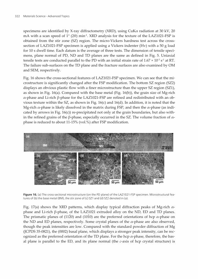
Fig. 16 shows the cross-sectional features of LAZ1021-FSP specimen. We can see that the mi‐crostructure is significantly changed after the FSP modification. The bottom SZ region (SZ2)displays an obvious plastic flow with a finer microstructure than the upper SZ region (SZ1),as shown in Fig. 16(a). Compared with the base metal (Fig. 16(b)), the grain size of Mg-richα-phase and Li-rich β-phase for the LAZ1021-FSP are refined and redistributed with an ob‐vious texture within the SZ, as shown in Fig. 16(c) and 16(d). In addition, it is noted that theMg-rich α-phase is likely dissolved in the matrix during FSP, and then the α-phase (as indi‐cated by arrows in Fig. 16(c)) re-precipitated not only at the grain boundaries, but also with‐in the refined grains of the β-phase, especially occurred in the SZ. The volume fraction of α-phase is reduced to about 11-15% (vol.%) after FSP modification.
50 µm
(b) α α
50 µm
(c)
50 µm
(d)
SZ1
BM SZ2 2 mm
(a)
α
α
α
Figure 16. (a) The cross-sectional microstructure (on the PD plane) of the LAZ1021-FSP specimen. Microstructural fea‐tures of (b) the base metal (BM), the stir zone of (c) SZ1 and (d) SZ2 denoted in (a).
Fig. 17(a) shows the XRD patterns, which display typical diffraction peaks of Mg-rich α-phase and Li-rich β-phase, of the LAZ1021 extruded alloy on the ND, ED and TD planes.The prismatic planes of (112̄0) and (101̄0) are the preferred orientations of hcp α-phase onthe ND and ED planes, respectively. Some crystal planes of the α-phase are also observed,though the peak intensities are low. Compared with the standard powder diffraction of Mg(JCPDS 35-0821), the (0002) basal plane, which displays a stronger peak intensity, can be rec‐ognized as the preferred orientation of the TD plane. For the hcp α-phase, therefore, the bas‐al plane is parallel to the ED, and its plane normal (the c-axis of hcp crystal structure) is
Materials Science - Advanced Topics322

perpendicular to the TD plane. As for the bcc β-phase, the (200) and (110) planes are identi‐fied as the preferred orientations of the ND plane and of both the ED and TD planes, respec‐tively. Apart from the peaks of α and β-phases, relatively weak peaks are also observed inFig. 17(a), and these peaks belong to the AlLi intermetallic compound (JCPDS 71-0362). Fig.17(b) shows the XRD patterns obtained from SZ regions on the ND, PD and TD planes of theLAZ1021-FSP specimen, respectively. Diffraction peaks of the AlLi intermetallic compoundis reduced, and it is recognized that the AlLi compound is dissolved after the FSP. It is notedthat the peaks intensity of the hcp α-phase is significantly reduced and the texture of extrud‐ed LAZ1021 alloy is changed after the FSP, especially for the ND plane of LAZ1021-FSPspecimens. We can see that the preferred orientation of the hcp α-phase is varied from theprismatic plane (112̄0) to the pyramidal plane (101̄1), and the bcc β-phase is varied from(200) to (110) on the ND plane. The reduction of diffraction peaks intensity for the α-phasecan be resulted from the decrease in the volume fraction of α-phase. The (110) plane of thebcc β-phase can be identified as the preferred orientation for the LAZ1021-FSP modifiedspecimens, as shown in Fig. 17(b).
17
0 3 6 90
50
100
150
Nor
mal
stre
ss (M
Pa)
Normal strain (%)
(a) (b) LAZ1021-FSP
As-extruded LAZ1021
SZ
Base metal
(200) to (110) on the ND plane. The reduction of diffraction peaks intensity for the α-phase can be resulted from the decrease in the volume fraction of α-phase. The (110) plane of the bcc β-phase can be identified as the preferred orientation for the LAZ1021-FSP modified specimens, as shown in Fig. 17(b). Fig. 17. X-ray diffraction patterns of (a) the as-extruded LAZ1021, and (b) the LAZ1021-FSP specimen.
Fig. 18(a) displays the microhardness (Hv) profiles along the cross-section of LAZ1021-FSP specimen. The dash line is the micrograph represents the Vickers indenter testing area, which is located at 1 mm depth from the surface. The result shows that the microhardness within SZ (average value of Hv72.5) is significantly increased and higher than the the base metal region. Fig. 18(b) displays the stress-strain curves of the as-extruded LAZ1021 alloy and the LAZ1021-FSP specimen. After FSP modification, the tensile strength is increased to about 180 MPa, but the elongation is significantly decreased for the LAZ1021-FSP specimen. The total elongation (TE) of LAZ1021 alloy is reduced from about 10% to about 3% after FSP. The variation of microhardness and tensile mechanical properties can be resulted from the microstructural features and preferred orientations (Figs. 16 and 17) are significantly varied with performing FSP modification. Fig. 19 shows the fracture surface and failure sub-surface of the LAZ1021-FSP specimen. Compared with the failure morphologies of as-extruded LAZ1021 alloy (Fig. 14(a) and 14(e)), the LAZ1021-FSP specimen displays an intergranular fracture feature, as shown in Fig. 19(a). Since the α-phase is precipitated at grain boundaries of the β-phase after FSP, it is recognized that the intergranular fracture can be resulted from the α/β-interface decohesion and the cracks propagation along the grain boundaries of β-phase, as shown in Fig. 19(b). Fig. 18. (a) Microhardness (Hv) of the LAZ1021-FSP. The indentations are made with a spacing of 0.5 mm along the parallel dash line. (b) The stress-strain curves of the as-extruded LAZ1021 alloy and the LAZ1021-FSP specimen.
20 40 60 80
Inte
nsity
(a.u
.)
2
(a)
ND
TD
ED
(2
00)
(2
11)
(1
120)
(1
122)
(1
10)
(1
010)
(1
011)
(1
010)
(000
2)
(2
20)
(0
002)
(2
20)
(2
11)
AlLi
20 30 40 50 60 70 80
TD
ED
ND
(degree)20 40 60 80
2θ
Inte
nsity
(a.u
.)
(b)
ND
TD
PD
(1
10)
(1
010)
(1
011)
(0
002)
(2
00)
(2
11)
(2
20)
(2
20)
(2
11)
(2
11)
(1
012)
(1
120)
(2
00)
(1
012)
(1
120)
(2
00)
Figure 17. X-ray diffraction patterns of (a) the as-extruded LAZ1021, and (b) the LAZ1021-FSP specimen.
Fig. 18(a) displays the microhardness (Hv) profiles along the cross-section of LAZ1021-FSPspecimen. The dash line is the micrograph represents the Vickers indenter testing area,which is located at 1 mm depth from the surface. The result shows that the microhardnesswithin SZ (average value of Hv72.5) is significantly increased and higher than the the basemetal region. Fig. 18(b) displays the stress-strain curves of the as-extruded LAZ1021 alloyand the LAZ1021-FSP specimen. After FSP modification, the tensile strength is increased toabout 180 MPa, but the elongation is significantly decreased for the LAZ1021-FSP specimen.The total elongation (TE) of LAZ1021 alloy is reduced from about 10% to about 3% after FSP.The variation of microhardness and tensile mechanical properties can be resulted from themicrostructural features and preferred orientations (Figs. 16 and 17) are significantly varied
Tensile Mechanical Properties and Failure Behaviors of Friction Stir Processing (FSP)…http://dx.doi.org/10.5772/54313
323

with performing FSP modification. Fig. 19 shows the fracture surface and failure sub-surfaceof the LAZ1021-FSP specimen. Compared with the failure morphologies of as-extrudedLAZ1021 alloy (Fig. 14(a) and 14(e)), the LAZ1021-FSP specimen displays an intergranularfracture feature, as shown in Fig. 19(a). Since the α-phase is precipitated at grain boundariesof the β-phase after FSP, it is recognized that the intergranular fracture can be resulted fromthe α/β-interface decohesion and the cracks propagation along the grain boundaries of β-phase, as shown in Fig. 19(b).
17
0 3 6 90
50
100
150N
orm
al st
ress
(MPa
)
Normal strain (%)
(a) (b) LAZ1021-FSP
As-extruded LAZ1021
SZ
Base metal
(200) to (110) on the ND plane. The reduction of diffraction peaks intensity for the α-phase can be resulted from the decrease in the volume fraction of α-phase. The (110) plane of the bcc β-phase can be identified as the preferred orientation for the LAZ1021-FSP modified specimens, as shown in Fig. 17(b). Fig. 17. X-ray diffraction patterns of (a) the as-extruded LAZ1021, and (b) the LAZ1021-FSP specimen.
Fig. 18(a) displays the microhardness (Hv) profiles along the cross-section of LAZ1021-FSP specimen. The dash line is the micrograph represents the Vickers indenter testing area, which is located at 1 mm depth from the surface. The result shows that the microhardness within SZ (average value of Hv72.5) is significantly increased and higher than the the base metal region. Fig. 18(b) displays the stress-strain curves of the as-extruded LAZ1021 alloy and the LAZ1021-FSP specimen. After FSP modification, the tensile strength is increased to about 180 MPa, but the elongation is significantly decreased for the LAZ1021-FSP specimen. The total elongation (TE) of LAZ1021 alloy is reduced from about 10% to about 3% after FSP. The variation of microhardness and tensile mechanical properties can be resulted from the microstructural features and preferred orientations (Figs. 16 and 17) are significantly varied with performing FSP modification. Fig. 19 shows the fracture surface and failure sub-surface of the LAZ1021-FSP specimen. Compared with the failure morphologies of as-extruded LAZ1021 alloy (Fig. 14(a) and 14(e)), the LAZ1021-FSP specimen displays an intergranular fracture feature, as shown in Fig. 19(a). Since the α-phase is precipitated at grain boundaries of the β-phase after FSP, it is recognized that the intergranular fracture can be resulted from the α/β-interface decohesion and the cracks propagation along the grain boundaries of β-phase, as shown in Fig. 19(b). Fig. 18. (a) Microhardness (Hv) of the LAZ1021-FSP. The indentations are made with a spacing of 0.5 mm along the parallel dash line. (b) The stress-strain curves of the as-extruded LAZ1021 alloy and the LAZ1021-FSP specimen.
20 40 60 80
Inte
nsity
(a.u
.)
2
(a)
ND
TD
ED
(2
00)
(2
11)
(1
120)
(1
122)
(1
10)
(1
010)
(1
011)
(1
010)
(000
2)
(2
20)
(0
002)
(2
20)
(2
11)
AlLi
20 30 40 50 60 70 80
TD
ED
ND
(degree)20 40 60 80
2θ
Inte
nsity
(a.u
.)
(b)
ND
TD
PD
(1
10)
(1
010)
(1
011)
(0
002)
(2
00)
(2
11)
(2
20)
(2
20)
(2
11)
(2
11)
(1
012)
(1
120)
(2
00)
(1
012)
(1
120)
(2
00)
Figure 18. (a) Microhardness (Hv) of the LAZ1021-FSP. The indentations are made with a spacing of 0.5 mm along theparallel dash line. (b) The stress-strain curves of the as-extruded LAZ1021 alloy and the LAZ1021-FSP specimen.
50 µm
(b)
α
α
50 µm
(a)
Figure 19. (a) Fracture surface, and (b) failure sub-surface on the TD plane of the LAZ1021-FSP specimen.
Materials Science - Advanced Topics324

6. Conclusion
The evolution of microstructural features, tensile mechanical properties and failure behav‐iors of full-annealed Mg-6Al-1Zn (AZ61-O) and as-extruded α/β-dual-phaseMg-10Li-2Al-1Zn (LAZ1021) alloys with applying a microstructural modification of the fric‐tion stir processing (FSP) are evaluated in this chapter. In summary, the grain size of AZ61-O and LAZ1021 alloys is significantly refined after the FSP modification. It is noted that thepreferred orientations of hcp Mg-rich α-phase and bcc Li-rich β-phase is changed for theLAZ1021-FSP specimens. The volume fraction of α-phase is reduced after FSP, and the for‐mation of a specific texture of the LAZ1021-FSP is resulted from the re-precipitation of α-phase within the grains and at the grain boundaries of β-phase in the stir zone (SZ). Afterthe FSP, the microhardness within SZ is significantly improved for both of the AZ61-O andLAZ1021 alloys.
Tensile strength is decreased and total elongation is increased with decreasing the initialstrain rate for both of the AZ61-O and AZ61-FSP. The serration of tensile stress-strain curvesfor AZ61-FSP specimens are resulted from the dynamic recrystallization (DRX) effect. TheDRX effect is activated at lower temperature and the driving force of DRX is much higherfor the AZ61-FSP modified specimens than the AZ61-O. Based on the evaluation of strainhardening exponent (n-value) and average grain size, it is demonstrated that the grain boun‐dary sliding (GBS) is a dominant deformation mechanism for the DRX during the tensile de‐formation performed at a lower strain rate and higher deformation temperatures for theAZ61-FSP specimens.
For α/β-dual-phase LAZ1021 alloy, the tensile strength is increased, but the total elongationis significantly decreased after the FSP modification. LAZ1021-FSP displays an intergranularfracture, which is occurred from the α/β-interface decohesion and crack propagation alongthe grain boundaries of β-phase. A significant ductile-to-brittle transition effect is confirmedfor the α/β-dual-phase Mg-Li-Al-Zn alloy. At temperatures lower than 25°C, fracturing oc‐curs by transgranular cleavage of the α-phase and intergranular fracture at grain boundariesof the β-phase. At deformation temperatures higher than 100°C, the dominant failure behav‐iors are interfacial cracking between α/β interface and ductile dimpled ruptures of the β-phase. The ductile-to-brittle transition occurred at temperatures between 25 and 100°C, andthe ductile-to-brittle transition temperature (DBTT) can be pinpointed at around 50°C for theα/β-dual-phase LAZ1021 alloy. The dimpled rupture for specimens with higher elongationis resulted from the cavitation due to the α/β interfacial cavities coalescence and interlink‐age. Failures with dimpled ruptures occurred from the cavitation is more significant withincreasing deformation temperatures.
Acknowledgements
This study was financially supported by the National Science Council of Taiwan (ContractNo. NSC 100-2221-E-150-037 and NSC 101-2221-E-150-028) for which we are grateful.
Tensile Mechanical Properties and Failure Behaviors of Friction Stir Processing (FSP)…http://dx.doi.org/10.5772/54313
325

Author details
Chung-Wei Yang
Department of Materials Science and Engineering, National Formosa University, Huwei,Yunlin, Taiwan
References
[1] Mordike BL, Ebert T. Magnesium properties-applications-potential. Materials Scienceand Engineering A 2001;302(1):37-45.
[2] Eliezer D, Aghion E, Froes FH. Magnesium science technology and applications. Ad‐vanced Performance Materials 1998;5:201-202.
[3] Deetz J. The use of wrought magnesium in bicycles. JOM 2005;57(5):50-53.
[4] Plomear IJ. Magnesium alloys and applications. Materials Science and Technology1994;10(1):1-16.
[5] Aghion E, Bronfin B. Magnesium alloys development towards the 21th century. Ma‐terials Science Forum 2000;350:19-28.
[6] VanFleteren R. Magnesium for automotive applications. Advanced Materials andProcesses 1996;149(5):33-34.
[7] Aghion E, Bronfin B, Eliezer D. The role of the magnesium industry in protecting theenvironment. Journal of Materials Processing Technology 2001;117:381-385.
[8] Wang HY, Li ZJ. Investigation of laser beam welding process of AZ61 magnesium-based alloy. Acta Metallurgica Sinica 2006;19(4):287-294.
[9] Padmanaban G, Balasubramanian V. Optimization of laser beam welding process pa‐rameters to attain maximum tensile strength in AZ31B magnesium alloy. Optics &Laser Technology 2010;42(8):1253-1260.
[10] Luo Y, Ye H, Du C, Xu H. Influence of focusing thermal effect upon AZ91D magnesi‐um alloy weld during vacum electron beam welding. Vacuum 2012;86(9):1262-1267.
[11] Thomas WM, Nicholas ED, Needham JC, Murch MG, Templesmith P, Dawes CJ. G.B. Patent Application, No. 9125978.8, 1991.
[12] Mahoney MW, Rhodes CG, Flintoff JG, Bingle WH, Spurling RA. Properties of fric‐tion-stir-welded 7075-T651 aluminum. Metallurgical and Materials Transactions A –Physical Metallurgy and Materials Science 1998;29(7):1955-1964.
[13] Squillace A, De Fenzo A, Giorleo G, Bellucci F. A comparison between FSW and TIGwelding techniques: modification of microstructure and pitting corrosion resistance
Materials Science - Advanced Topics326

in AA 2024-T3 butt joints. Journal of Materials Processing Technology 2004;152(1):97-105.
[14] Padmanaban G, Balasubramanian V. Metallurgical characterization of pulsed currentgas tungsten arc, friction stir and laser beam welded AZ31B magnesium alloy joints.Materials Chemistry and Physics 2011;125(3):686-697.
[15] Wang X, Wang K. Microstructure and properties of friction stir butt-welded AZ31magnesium alloy. Materials Science and Engineering A 2006;431:114-117.
[16] Xie GM, Ma ZY, Geng L, Chen RS. Microstructural evolution and mechanical proper‐ties of friction stir welded Mg-Zn-Y-Zr alloy. Materials Science and Engineering A2007;471:63-68.
[17] Dobriyal RP, Dhindaw BK, Muthukumaran S, Mukherjee SK. Microstructure andproperties of friction stir butt-welded AE42 magnesium alloy. Materials Science andEngineering A 2008;477(1-2):243-249.
[18] Cerri E, Leo P. Warm and room temperature deformation of friction stir welded thinaluminum sheets. Materials & Design 2010;31(3):1392-1402.
[19] Fratini L, Micari F, Buffa G, Ruisi VF. A new fixture for FSW processes of titaniumalloys. CIRP Annals – Manufacturing Technology 2010;59(1):271-274.
[20] Somasekharan AC, Murr LE. Microstructures in friction-stir welded dissimilar mag‐nesium alloys and magnesium alloys to 6061-T6 aluminum alloy. Materials Charac‐terization 2004;52(1):49-64.
[21] Yan Y, Zhang DT, Qiu C, Zhang W. Dissimilar friction stir welding between 5052aluminum alloy and AZ31 magnesium alloy. Transactions of Nonferrous Metals So‐ciety of China 2010;20(2):s619-s623.
[22] Xue P, Ni DR, Wang D, Xiao BL, Ma ZY. Effect of friction stir welding parameters onthe microstructure and mechanical properties of the dissimilar Al-Cu joints. Materi‐als Science and Engineering A 2011;528(13-14):4683-4689.
[23] Anouma M, Nakata K. Effect of alloying elements on interface microstructure of Mg-Al-Zn magnesium alloys and titanium joint by friction stir welding. Materials Scienceand Engineering B 2009;161(1-3):46-49.
[24] Anouma M, Nakata K. Dissimilar metal joining of ZK60 magnesium alloy and titani‐um by friction stir welding. Materials Science and Engineering B 2012;177(7):543-548.
[25] Clark JB. Age hardening in a Mg-9wt.%Al alloy. Acta Metallurgica 1968;16(2):141-152.
[26] Foerster GS. Proceeding of the IMA 33rd Annual Meeting, May 23-25, 1976, Mon‐treal, Quebec, Canada, p.35-39.
[27] Hono K, Mendis CL, Sasaki TT, Oh-ishi K. Towards the development of heat-treata‐ble high-strength wrought Mg alloys. Scripta Materialia 2010;63:710-715.
Tensile Mechanical Properties and Failure Behaviors of Friction Stir Processing (FSP)…http://dx.doi.org/10.5772/54313
327

[28] Miller WK. Creep of die cast AZ91 magnesium at room temperature and low stress.Metallurgical and Materials Transactions A – Physical Metallurgy and Materials Sci‐ence 1991;22(4):873-877.
[29] Luo A, Pekguleryuz MO. Cast magnesium alloys for elevated temperature applica‐tions. Journal of Materials Science 1994;29(20):5259-5271.
[30] Zhang J, Li ZS, Guo ZX, Pan FS. Solidification microstructural constituent and itscrystallographic morphology of permanent-mold-cast Mg-Zn-Al alloys. Transactionsof Nonferrous Metals Society of China 2006;16:452-458.
[31] Xiao W, Jia S, Wang J, Wu Y, Wang L. Effects of cerium on the microstructure andmechanucal properties of Mg-20Zn-8Al alloy. Materials Science and Engineering A2008;474:317-322.
[32] Zhang J, Guo ZX, Pan F, Li Z, Luo X. Effect of composition on the microstructure andmechanical properties of Mg-Zn-Al alloys. Materials Science and Engineering A2007;456(1-2):43-51.
[33] Pekguleryuz MO, Baril E. Creep resistant magnesium diecasting alloys based on al‐kaline earth elements. Materials Transactions 2001;42(7):1258-1367.
[34] Luo AA, Powell BR, Balogh MP. Creep and microstructure of magnesium-alumi‐num-calcium based alloys. Metallurgical and Materials Transactions A – PhysicalMetallurgy and Materials Science 2002;33(3):567-574.
[35] Luo AA. Recent magnesium alloy development for elevated temperature applica‐tions. International Materials Reviews 2004;49(1):13-30.
[36] Saddock ND, Suzuki A, Jones JW, Pollock TM. Grain-scale creep processes in Mg-Al-Ca base alloys: Implications for alloy design. Scripta Materialia 2010;63:692-697.
[37] Lu YZ, Wang QD, Zeng XQ. Effects of rare earths on the microstructure, propertiesand fracture behavior of Mg-Al alloys. Materials Science and Engineering A2000;278(1-2):66-76.
[38] Zhou HT, Zhang XQ, Ding WJ, Ma CJ, Zhu YP. Effect of La and Nd on microstruc‐tures and mechanical properties of AZ61 wrought magnesium alloy. Transactions ofNonferrous Metals Society of China 2004;14(1):67-70.
[39] Wang MX, Zhou H, Wang L. Effect of yttrium and cerium addition on microstructureand mechanical properties of AM50 magnesium alloy. Journal of Rare Earths2007;25(2):233-237.
[40] Zhang J, Wang J, Qiu X, Zhang D, Tian Z, Niu X, Tang D, Meng J. Effect of Nd on themicrostructure, mechanical properties and corrosion behavior of die-cast Mg-4Al-based alloy. Journal of Alloys and Compounds 2008;464(1-2):556-564.
[41] Pan FS, Chen MB, Wang JF, Peng J, Tang AT. Effect of yttrium addition on micro‐structure and mechanical properties of as-extruded AZ31 magnesium alloys. Trans‐actions of Nonferrous Metals Society of China 2008;18:s1-s6.
Materials Science - Advanced Topics328

[42] Zhang J, Liu K, Fang D, Qiu X, Tang D, Meng J. Microstructure, tensile propertiesand creep behavior of high pressure die-cast Mg-4Al-4RE-0.4Mn (RE=La, Ce) alloys.Journal of Materials Science 2009;44(8):2046-2054.
[43] Kaveh MA, Afshin M, Farzad K. The effect of different rare earth elements content onmicrostructure, mechanical and wear behavior of Mg-Al-Zn alloy. Materials Scienceand Engineering A 2010;527(7-8):2027-2035.
[44] Tong G, Liu H, Liu Y. Effect of rare earth additions on microstructure and mechani‐cal properties of AZ91 magnesium alloys. Transactions of Nonferrous Metals Societyof China 2010;20:s336-s340.
[45] Zou H. Effect of microstructure on creep behavior Mg-5%Zn-2%Al (-2%Y) alloy.Transactions of Nonferrous Metals Society of China 2008;18(3):580-587.
[46] Xiao W, Jia S, Wang L, Wu Y, Wang L. The microstructure and mechanical propertiesof Mg-Zn-Al-RE alloys. Journal of Alloys and Compounds 2009;480(2):L33-L36.
[47] Wei LY, Dunlop GL, Westengen H. Age hardening and precipitation in a cast magne‐sium-rare-earth alloy. Journal of Materials Science 1996;31(2):387-397.
[48] Nie JF, Muddle BC. Characterization of strengthening precipitate phases in a Mg-Y-Nd alloy. Acta Materialia 2000;48(8):1691-1703.
[49] Smola B., Stulikova I., Pelcova J., Mordike L. Magnesium Alloys and Their Applica‐tions. In: Kainer K.U. (ed.) Wiley-VCH Verlag, Weinheim; 2003, p43.
[50] Kawamura Y, Hayashi K, Inoue A, Masumoto T. Rapid solidified powder metallurgyMg97Zn1Y2 alloys with excellent tensile yield strength above 600 MPa. MaterialsTransactions 2001;42(7):1172-1176.
[51] Homma T, Kunito N, Kamado S. Fabrication of extraordinary high-strength magnesi‐um alloy by hot extrusion. Scripta Materialia 2009;61(6):644-647.
[52] Hagihara K, Kinoshita A, Sugino Y, Yamasaki M, Kawamura Y, Yasuda HY, Uma‐koshi Y. Effect of long-period stacking ordered phase on mechanical properties ofMg97Zn1Y2 extruded alloy. Acta Materialia 2010;58(19):6282-6293.
[53] Yamasaki M, Hashimoto K, Hagihara K, Kawamura Y. Effect of multimodal micro‐structure evolution on mechanical properties of Mg-Zn-Y extruded alloy. Acta Mate‐rialia 2011;59(9):3646-3658.
[54] Matsuda M, Ii S, Kawamura Y, Ikuhara Y, Nishida M. Interaction between long peri‐od stacking order phase and deformation twin in rapidly solidified Mg97Zn1Y2 alloy.Materials Science and Engineering A 2004;386(1-2):447-452.
[55] Hagihara K, Kinoshita A, Sugino Y, Yamasaki M, Kawamura Y, Yasuda HY, Uma‐koshi Y. Plastic deformation behavior of Mg97Zn1Y2 extruded alloys. Transactions ofNonferrous Metals Society of China 2010;20(7):1259-1268.
Tensile Mechanical Properties and Failure Behaviors of Friction Stir Processing (FSP)…http://dx.doi.org/10.5772/54313
329

[56] Yamasaki M, Sasaki M, Nishijima M, Hiraga K, Kawamura Y. Formation of 14H longperiod stacking ordered structure and profuse stacking faults in Mg-Zn-Gd alloysduring isothermal aging at high temperature. Acta Materialia 2007;55(20):6798-6805.
[57] Yamasaki M, Anan T, Yoshimoto S, Kawamura Y. Mechanical properties of warm-extruded Mg-Zn-Gd alloy with coherent 14H long perodic staking ordered structureprecipitate. Scripta Materialia 2005;53(7):799-803.
[58] Yamasaki M, Izumi H, Kawamura Y, Habazaki H. Corrosion and passivation behav‐ior of Mg-Zn-Y-Al alloys prepared by cooling-rate controlled solidification. AppliedSurface Science 2011;257(19):8258-8267.
[59] Haferkamp H, Boehm R, Holzkamp U, Jaschik C, Kaese V, Niemeyer M. Alloy devel‐opment, processing and applications in magnesium lithium alloys. Materials Trans‐actions 2001;42:1160-1166.
[60] Wang JY, Hong WP, Hsu PC, Tan L. Microstructures and mechanical behavior ofprocessed Mg-Li-Zn alloy. Materials Science Forum 2003;419-422:165-170.
[61] Massalski T, Okamoto H, Subramanian P, Kacprzak L. Binary alloy phase diagrams.United States of America: ASM International; 2001, p.2445.
[62] Matsuzawa K, Koshihara T, Kojima Y. Age-hardening and mechanical properties ofMg-Li-Al alloys. Journal of Japan Institute of Light Metals 1989;39(1):45-51.
[63] Song JM, Wen TX, Wang JY. Vibration fracture properties of a lightweight Mg-Li-Znalloy. Scripta Materialia 2007;56:529-532.
[64] Metenier P, Gonzalez-Doncel G, Ruano OA, Wolfenstine J, Sherby DD. Superplasticbehavior of a fine-grained two-phase Mg-9wt.%Li alloy. Materials Science and Engi‐neering A 1990;125(2):195-202
[65] Sivakesavam O, Prasad YVRK. Characteristics of superplasticity domain in the proc‐essing map for hot working of as-cast Mg-11.5Li-1.5Al alloy. Materials Science andEngineering A 2002;323(1-2):270-277.
[66] Dong SL, Imai T, Lim SW, Kanetake N, Saito N. Superplasticity evaluation in anMg-8.5Li alloy. Journal of Materials Science 2007;42(13):5296-5298.
[67] Cao FR, Ding H, Li YL, Zhou G, Cui JZ. Superplasticity, dynamic grain growth anddeformation mechanism in ultra-light two-phase magnesium-lithium alloys. Materi‐als Science and Engineering A 2010;527:2335-2341.
[68] Liu X, Du G, Wu, R, Niu Z, Zhang M. Deformation and microstructure evolution of astrain rate superplastic Mg-Li-Zn alloy. Journal of Alloys and Compounds2011;509(39):9558-9561.
[69] Clark J, Sturkey L. The age-hardening mechanism in magnesium-lithium-zinc alloys.The Japan Institute of Metals 1957;86:272-276.
Materials Science - Advanced Topics330

[70] Alamo A, Banchik D. Precipitation phenomena in the Mg-31at% Li-1 at% Al alloy.Journal of Materials Science 1980;15:222-229.
[71] Hatta H, Ramesh C, Kamado S, Kojima Y. Heat treatment characteristics and me‐chanical properties of superlight Mg-Li-Al alloys. Journal of Japan Institute of LightMetals 1997;47(4):202-207.
[72] Saito N, Mabuchi M, Nakanishi M, Kubota K, Higashi K. The aging behavior and themechanical properties of the Mg-Li-Al-Cu alloy. Scripta Materialia 1997;36:551-555.
[73] Takuda H, Matsusaka H. Tensile properties of a few Mg-Li-Zn alloy thin sheets.Journal of Materials Science 2002;37:51-57.
[74] Yamamoto A, Ashida T, Kouta Y, Kim KB, Fukumoto S, Tsubakino H. Precipitationin Mg-(4-13)%Li-(4-5)%Zn ternary alloys. Materials Transactions 2003;44(4):619-624.
[75] Song GS, Staiger M, Kral M. Some new characteristics of the strengthening phase inβ-phase magnesium-lithium alloys containing aluminum and beryllium. MaterialsScience and Engineering A 2004;371:371-376.
[76] Hsu CC, Wang JY, Lee S. Room temperature aging characteristic of MgLiAlZn alloy.Materials Transactions 2008;49(11):2728-2731.
[77] Chiu CH, Wu HY, Wang JY, Lee S. Microstructure and mechanical behavior of LZ91Mg alloy processed by rolling and heat treatments. Journal of Alloys and Com‐pounds 2008;460:246-252.
[78] Wang PC, Lin HC, Lin KM, Yeh MT, Lin CY. A study of aging treatment on theMg-10Li-0.5Zn alloy. Materials Transactions 2009;50(9):2259-2263.
[79] Puleo DA, Huh WW. Acute toxicity of metal ions in cultures of osteogenic cells de‐rived from bone marrow stromal cells. Journal of Applied Biomaterials1995;6:109-116
[80] Jacobs JJ, Skipor AK, Patterson LM, Hallab NJ, Paprosky WG, Black J, Galante JO.Metal release in patients who have had a primary total hip arthroplasty. A prospec‐tive, controlled, longitudinal study. Journal of Bone Joint Surgury 1998;80:1447-1458.
[81] Lhotka C, Szekeres T, Steffan I, Zhuber K, Zweymuller K. Four-year study of cobaltand chromium blood levels in patients managed with two different metal-on-metaltotal hip replacements. Journal of Orthopaedic Research 2003;21:189-195.
[82] Nagels J, Stokdijk M, Rozing PM. Stress shielding and bone resorption in shoulderarthroplasty. Journal of Shoulder and Elbow Surgery 2003;12:35-39.
[83] Witte F, Fischer J, Nellesen J, Crostack HA, Kaese V, Pischd A. In vitro and in vivocorrosion measurements of magnesium alloys. Biomaterials 2006;27:1013-1018.
[84] Witte F, Kaese V, Switzer H, Maeyer-Lindenberg A, Wirth CJ, Windhag H. In vivocorrosion of four magnesium alloys and the associated bone response. Biomaterials2005;26:3557-3563.
Tensile Mechanical Properties and Failure Behaviors of Friction Stir Processing (FSP)…http://dx.doi.org/10.5772/54313
331

[85] Staiger MP, Pietak AM, Huadmai J, Dias G. Magnesium and its alloys as orthopedicbiomaterials: a review. Biomaterials 2006;27:1728-1734.
[86] Okuma T. Magnesium and bone strength. Nutrition 2001;17:679-680.
[87] Vormann J. Magnesium: nutrition and metabolism. Molecular Aspects of Medicine2003;24:27-37.
[88] Revell PA, Damien E, Zhang XS, Evans P, Howlett CR. The effect of magnesium ionson bone bonding to hydroxyapatite. Key Engineering Materials 2004;254-256:447-450.
[89] Zreiqat H, Howlett CR, Zannettino A, Evans P, Schulze-Tanzil G, Knabe C, et al.Mechanisms of magnesium-simulated adhesion of osteoblastic cells to commonlyused orthopaedic implants. Journal of Biomedical Materials Research2002;62:175-184.
[90] Stroganov GB, Savitsky E, Mikhailovich T, Nina M, Terekhova V, Fedorovna V et al.(1972). Magnesium-base alloys for use in bone surgery. US Patent No. 3,687,135.
[91] Li Z, Gu X, Lou S, Zheng Y. The development of binary Mg-Ca alloys for use as bio‐degradable materials with bone. Biomaterials 2008;29:1329-1344.
[92] Gao L, Zhang C, Zhang M, Huang, X, Sheng N. The corrosion of a novelMg-11Li-3Al-0.5RE alloy in alkaline NaCl solution. Journal of Alloys and Com‐pounds 2009;468: 285-289.
[93] Zhang S, Li J, Song Y, Zhao C, Zhang X, Xie C, Zhang Y, Tao H, He Y, Jiang Y, BianY. In vitro degradation, hemolysis and MC3T3-E1 cell adhesion of biodegradableMg-Zn alloy. Materials Science and Engineering C 2009;29:1907-1912.
[94] Tsai MH, Chen MS, Lin LH, Lin MH, Wu CZ, Ou KL, Yu CH. Effect of heat treatmenton the microstructures and damping properties of biomedical Mg-Zr alloy. Journal ofAlloys and Compounds 2011;509:813-819.
[95] Gray JE, Luan B. Protective coatings on magnesium and its alloys – a critical review.Journal of Alloys and Compounds 2002;336:88-113.
[96] Shi Z, Song G, Atrens A. Influence of anodizing current on the corrosion resistance ofanodized AZ91D magnesium alloy. Corrosion Science 2006;48:1939-1959.
[97] Yu BL, Uan JY. Sacrificial Mg film anode for cathodic protection of die cast Mg-9wt.%Al-1wt.%Zn alloy in NaCl aqueous solution. Scripta Materialia 2006;54:1253-1257.
[98] Ono S, Asami K, Masuko N. Mechanism of chemical conversion coating film growthon magnesium and magnesium alloys. Materials Transactions 2001;42:1225-1231.
[99] Elsentriecy HH, Azumi K, Konno H. Improvement in stannate chemical conversioncoatings on AZ91D magnesium alloy using the potentiostatic technique. Electrochi‐mica Acta 2007;53(2):1006-1012.
Materials Science - Advanced Topics332

[100] Lin CS, Lee CY, Li WC, Chen YS. Fang GN. Formation of phosphate/permanganateconversion coating on AZ31 magnesium alloy. Journal of the Electrochemical Society2006;153:B90-B96.
[101] Lin JK, Hsia CL, Uan JY. Characterization of Mg,Al-hydrotalcite conversion film onMg alloy and Cl- and CO3
2¯ anion-exchangeability of the film in a corrosive environ‐ment. Scripta Materialia 2007;56:527-530.
[102] Lin JK, Uan JY. Formation of Mg,Al-hydrotalcite conversion coating on
[103] Mg alloy in aqueous HCO2¯/CO3
2¯ and corresponding protection against corrosion bythe coating. Corrosion Science 2009;51:1181-1188.
[104] Miyata S, Okada A. Synthesis of hydrotalcite-like compounds and their physico-chemical properties. Clays and Clay Minerals 1977;25:14-18.
[105] Qiu R, Iwamoto C, Satonaka S. Interfacial microstructure and strength of steel/alumi‐num alloy joints welded by resistance spot welding with cover plate. Journal of Ma‐terials Processing Technoligy 2009;209(8):4186-4193.
[106] Ambroziak A, Korzeniowski M. Using resistance spot welding for joining aluminumelements in automotive. Archives of Civil and Mechanical Engineering 2010;10(1):5-13.
[107] Hayat F. The effect of the welding current on heat input, nugget geometry, and themechanical and fractural properties of resistance spot welding on Mg/Al dissimilarmaterials. Materials & Design 2011;32(4):2476-2484.
[108] Xu W, Chen DL, Liu L, Mori H, Zhou Y. Microstructure and mechanical properties ofweld-bonded and resistance spot welded magnesium-to-steel dissimilar joints. Mate‐rials Science and Engineering A 2012;537(1):11-24.
[109] Kishore Babu N, Brauser S, Rethmeier M, Cross CE. Characterizaton of microstruc‐ture and deformation behaviour of resistance spot welded AZ31 magnesium alloy.Materials Science and Engineering A 2012;549(15):149-156.
[110] Thornton PH, Krause AR, Davies RG. Aluminum spot weld. Welding Journal1996;75(3):101s-108s.
[111] Fukumoto S, Lum I, Biro E, Boomer DR Zhou Y. Effects of electrode degradation onelectrode life in resistance spot welding of aluminum alloy 5182. Welding Journal2003;82(11):307s-312s.
[112] Lang B, Sun DQ, Li GZ, Zhu BQ. Electrode degradation in resistance spot welding ofmagnesium alloy. ISIJ International 2009;49(11):1744-1748.
[113] Mishra RS, Mahoney MW, McFadden SX, Mara NA, Mukherjee AK. High strain ratesuperplasticity in a friction stir processed 7075 Al alloy. Scripta Materialia 2000;42(2):163-168.
Tensile Mechanical Properties and Failure Behaviors of Friction Stir Processing (FSP)…http://dx.doi.org/10.5772/54313
333

[114] Mishra RS, Mahoney MW. Friction stir processing: A new grain refinement techni‐que to achieve high strain rate superplasticity in commercial alloys. Materials ScienceForum 2001;357-359:507-514.
[115] Mishra RS, Ma ZA. Friction stir welding and processing. Materials Science and Engi‐neering R 2005;50:1-78.
[116] Jata KV, Semiatin SL. Continuous dynamic recrystallization during friction stir weld‐ing of high strength aluminum alloys. Scripta Materialia 2000;43(8):743-749.
[117] Chang CI, Lee CJ, Huang JC. Relationship between grain size and Zener-Hollomanparameter during friction stir processing in AZ31 Mg alloys. Scripta Materialia2004;51(6):509-514.
[118] Woo W, Choo H, Prime MB, Feng Z, Clausen B. Micristructure, texture and residualstress in a friction-stir-processed AZ31B magnesium alloy. Acta Materialia 2008;56(8):1701-1711.
[119] Yu S, Chen X, Huang Z, Liu Y. Microstructure and mechanical properties of frictionstir welding of AZ31B magnesium alloy added with cerium. Journal of Rare Earths2010;28(2):316-320.
[120] Chowdhury SH, Chen DL, Bhole SD, Cao X, Wanjara P. Friction stir welded AZ31magnesium alloy: microstructure, texture, and tensile properties. Metallurgical andMaterials Transactions A – Physical Metallurgy and Materials Science 2012; DOI:10.1007/s11661-012-1382-3.
[121] Hirata T, Oguri T, Hagino H, Tanaka T, Chung SW, Takigawa Y, Higashi K. Influ‐ence of friction stir welding parameters on grain size and formability in 5083 alumi‐num alloy. Materials Science and Engineering 2007;456:344-349.
[122] Cao X, Jahazi M. Effect of welding speed on the quality of friction stir welded buttjoints of a magnesium alloy. Materials & Design 2009;30(6):2033-2042.
[123] Yang J, Wang D, Xiao BL, Ni DR, Ma ZY. Effects of rotation rates on microstructure,mechanical properties and fracture behavior of friction stir-welded (FSW) AZ31 mag‐nesium alloy. Metallurgical and Materials Transactions A – Physical Metallurgy andMaterials Science 2012;DOI:10.1007/s11661-012-1373-4.
[124] Park SHC, Sato YS, Kokawa H. Effect of micro-texture on fracture location in frictionstir weld of Mg alloy AZ61 during tensile test. Scripta Materialia 2003;49(2):161-166.
[125] Park SHC, Sato YS, Kokawa H. Basal plane texture and flow pattern in friction stirweld of a magnesium alloy. Metallurgical and Materials Transactions A – PhysicalMetallurgy and Materials Science 2003;34(4):987-994.
[126] Woo W, Choo H, Brown DW, Liaw PK, Feng Z. Texture variation and its influenceon the tensile behavior of a friction-stir processed magnesium alloy. Scripta Materia‐lia 2006;54:1859-1864.
Materials Science - Advanced Topics334

[127] Feng AH, Ma ZY. Enhanced mechanical properties of Mg-Al-Zn cast alloy via fric‐tion stir processing. Scripta Materialia 2007;56:397-400.
[128] Afrin N, Chen DL, Cao X, Jahazi M. Microstructure and tensile properties of frictionstir welded AZ31B magnesium alloy. Materials Science and Engineering A2008;472(1-2):179-186.
[129] Zhang DT, Suzuki M, Maruyama K. Study on the texture of a friction stir weldedMg-Al-Ca alloy. Acta Metallurgica Sinica 2009;48(2):335-340.
[130] Mansoor B, Ghosh AK. Microstructure and tensile behavior of a friction stir process‐ed magnesium alloy. Acta Mateialia 2012;60(13-14):5079-5088.
[131] Lathabai S, Painter MJ, Cantin GMD, TyagiVK. Friction spot joining of an extrudedAl-Mg-Si alloy. Scripta Materialia 2006;55(10):899-902.
[132] Chen YC, Nakata K. Friction stir lap joining aluminum and magnesium alloys. Scrip‐ta Materialia 2008;58(6):433-436.
[133] Yang CW, Hung FY, Lui TS, Chen LH, Juo JY. Weibull statistics for evaluating failurebehaviors and joining reliability of friction stir spot welded 5052 aluminum alloy.Materials Transactions 2009;50(1):145-151.
[134] Yin YH, Ikuta A, North TH. Microstructural features and mechanical properties ofAM60 and AZ31 friction stir spot welds. Materials & Design 2010;31(10):4764-4776.
[135] Chen YC, Gholinia A, Prangnell PB. Interface structure and in bonding and abrasioncircle friction stir spot welding: A novel approach for rapid welding aluminum alloyto steel automotive sheets. Materials Chemistry and Physics 2012;134(1):459-463.
[136] Sun YF, Fujii H, Takaki N, Okitsu Y. Microstructure and mechanical properties ofmild steel joints prepared by a flat friction stir spot welding technique. Materials &Design 2012;37:384-392.
[137] Lin PC, Lin SH, Pan J, Pan T, Nicholson JM, Garman MA. SAE Technical Paper No.2004-01-1330, Society of Automotive Engineering, Warrendale, PA; 2004.
[138] Kaibyshev R, Stidikov O. Dynamic recrystallization of magnesium at ambient tem‐perature. Zeitschrift fuer Metallkunde 1994;85:738-743.
[139] McQueen HJ, Imbert CAC. Dynamic recrystallization: plastic enhancing structuraldevelopment. Journal of Alloys and Compounds 2004;378:35-43.
[140] Humphreys FJ, Hotherly M. Recrystallization and Related Annealing Phenomena.New York: Pergamon Press; 1995.
[141] Watanabe H, Mukai T, Kohzu M, Tanabe S, Higashi K. Effect of temperature andgrain size on the dominant diffusion process for superplastic flow in an AZ61 mag‐nesium alloy. Acta Materialia 1999;47:3753-3758.
[142] Lynch SP, Muddle BC, Pasang T. Ductile-to-brittle fracture transitions in 8091 Al-Lialloys. Acta Materialia 2001;49(15):2863-2874.
Tensile Mechanical Properties and Failure Behaviors of Friction Stir Processing (FSP)…http://dx.doi.org/10.5772/54313
335

[143] Argon AS. Mechanics and physics of brittle to ductile transitions in fracture. Journalof Engineering Materials Technology, Transactions of the ASME 2001;123(1):1-11.
[144] Crocker AG, Flewitt PEJ, Smith GE. Computational modelling of fracture in poly‐crystalline materials. International Materials Reviews 2005;50(2):99-124.
[145] Russell AM, Chumbley LS, Gantovnik VB, Xu K, Tian Y, Laabs FC. Anomalouslyhigh impact fracture toughness in BCC Mg-Li between 4.2K and 77K. Scripta Materi‐alia 1998;39:1663-1667.
[146] Counts WA, Friák M, Raabe D, Neugebauer J. Using ab initio calculations in design‐ing bcc Mg-Li alloys for ultra-lightweight applications. Acta Materialia 2009;57(1):69-76.
[147] Hughes GM, Flewitt PEJ. Temperature dependence of mechanical properties of zincand Zircaloy measured using miniaturized disc tests. Materials Science and Technol‐ogy 2008;24(5):567-574.
[148] Yang CW, Lui TS, Chen LH, Hung HE. Tensile mechanical properties and failure be‐haviors with the ductile-to-brittle transition of the α+β-type Mg-Li-Al-Zn alloy.Scripta Materialia 2009;61:1141-1144.
[149] Bae DH, Ghosh AK. Cavity formation and early growth in a superplastic Al-Mg aloy.Acta Materialia 2002;50(3): 511-523.
[150] Drozd Z, Trojanová Z, Kúdela S. Deformation behavior of Mg-Li-Al alloys. Journal ofAlloys Compounds 2004;378(1-2):192-195.
[151] Agnew SR, Horton JA, Yoo MH. Transmission electron microscopy investigation of<c+a> dislocations in Mg and α-solid solution Mg-Li alloys. Matallurgical and Mate‐rials Transactions A – Physical Metallurgy and Materials Science 2002;33(3):851-858.
Materials Science - Advanced Topics336