tender no: iuac/nit/19/ugn/2016-17 · ring main unit 22 transformer 26 ... tender no:...
TRANSCRIPT
INTER UNIVERSITY ACCELERATOR CENTRE
ARUNA ASAF ALI MARG, POST BOX NO. 10502
TENDER NO: IUAC/NIT/19/UGN/2016-17
Name of the work : Supply, Installation, Testing and Commissioning of 2MVA,
11KV/433V, Compact Substation
CONTENTS Page No
Notice inviting tender 2
General conditions of Tender 3
Scope of contract work 8
Detailed Technical Specifications
Section-I M V Panel 10
APFC panel 12
11 kV cables 14
LT Cables 15
Earthing 16
Section-II COMPACT SUBSTATION
Codes 19
Enclosure 21
Ring main Unit 22
Transformer 26
GTP 30
LT panel 33
Tests 34
Annexure I –List of submittals with bid 35
Annexure II - List of submittals after award of work 36
Annexure III - List of submittals prior to dispatch 37
Annexure IV –Code and Standards 38
Annexure V Confirmation/deviation by Tenderer 41
Annexure VI - GTP of CSS (Data by tenderer) 45
Annexure VII –Recommended Spares 52
Annexure VIII –List of approved makes 53
Abstract of cost 54
Schedule of prices 55-59

INTER UNIVERSITY ACCELERATOR CENTRE (IUAC)
(AUTONOMOUS CENTRE OF UNIVERSITY GRANT COMMISSION) NEW
DELHI
NOTICE INVITING TENDER
TENDER NO: IUAC/NIT/19/UGN/2016-17
Name of the work : Supply, Installation, Testing and Commissioning of 2MVA,
11KV/433V, Compact Substation
Estimated Amount : Rs. 45 Lakhs
Earnest Money : Rs. 90,000/- in the form of D. D.
Tender Cost : Rs. 500/- in cash or D. D
Last Date and Time of Submission
of Tender : 03/03/2017 at 3 p.m.
Date & Time for opening of Tender
(Techno-commercial bid - Part-A) : 03/03/2017 at 3.30 p.m.
Date & time for opening of Price Bid : To be intimated later on to technically
(Part-B). qualified tenderers.
Address for submission of tender : Administrative Officer (S&P),
Inter University Accelerator Centre
Aruna Asaf Ali Marg
Post Box: 10 502
New Delhi-110067.
Place of opening of the Tender : Committee Room in above address.
Tender Documents can be purchased from Administrative Officer(S&P), at a cost of Rs. 500/- (Rupees
Five Hundred Only) either in cash or Demand draft. The tender documents can also be downloaded from
IUAC web site “www.iuac.res.in”. Tender fee is also payable even if tender documents are downloaded.
For any clarifications / amendments / corrigenda etc. to NIT before last date of submission of tender will
only be available on our website “www.iuac.res.in” and Tenderers are requested to keep visiting the web
site.
GENERAL CONDITIONS OF TENDER:
1. Submission of Tender: Tenders should be submitted in sealed envelopes in two parts
separately, i.e. "Techno-commercial bid" (Part-A) and "Price bid" (Part-B). Both the parts
should be further sealed in an envelope super-scribing NIT No & name of work, due date
for opening, tenderers name & address. The tender duly filled in may be sent to above
mentioned address either by post or hand delivered in the tender box kept in the area near
west side entrance, after ensuring that due entries are made in the register kept at the
counter. It should not be handed over to any employee of the Centre. No tender shall be
accepted later than the time schedule specified above. Tender once submitted will remain
with IUAC and never be returned to the tenderers.
2. Techno-commercial Bid (Part-A): In this bid, the tenderer should submit his company
profile, history and structure of firm, name of directors/partners/proprietor with technical
staff, list of plant, machinery & tools in his possession, copies of work orders successfully
executed during the last 5 years, copy of Income tax clearance certificate for last two years.
No deviations in respect of NIT conditions are acceptable. The following specific
conditions are essential for technical qualification.
i). Copies of work orders for “Supply, Installation, Testing and Commissioning of
11KV/433V, Compact Substation” successfully completed works during last seven years
ending 31/01/2017 for reputed Public Ltd. Companies, Public Sector and other Govt.
Institutions in the following manner:
Three similar completed works each of value not less than 18 Lakhs with capacity of
individual transformer being 1600KVA.
OR
Two similar completed works each of value not less than 23.0 lakhs with capacity of
individual transformer being 1600KVA.
OR
One similar completed work of value not less than 36.0lakhs with capacity of individual
transformer being 1600KVA.
Similar Works means Supply, Installation, Testing and Commissioning of packaged compact substation including all HT & MV switch gears, panels & transformer.
ii). The tenderer must have a valid Electrical Contractor's License issued by any State / Union
government. Copy of the license must be submitted.
iii). Earnest Money Deposit.
iv). Entire NIT (except Price bid) duly signed & stamped by the tenderer.
v). Detailed technical specifications/ leaflets of the system offered.
vi). Satisfactory work completion certificate from at least one client with contract details. The
work order and completion certificate should be for the same work
vii). List of submittals as per the annexure-I
viii). The Centre reserves the right to either visit the works of the tenderers and the similar site
of installations of the tenderers and carryout the verification of the works claimed to have
been completed by them during last five years for qualification of their bids.
3. Price Bid (Part-B): In this bid the tenderer is required to quote his items rates/prices for
the works mentioned in the scope of work & technical specifications. The rates/price
should be inclusive of all material cost, labour, services, charges for the
plant/machinery/tools & tackles required for completion of work, freight, insurance,
Octroi, Govt. duties, taxes, levies up to IUAC site basis. No charges towards quantity
variations, escalation, site difficulties, other hidden cost even though they may not have
been explicitly mentioned in the scope and schedule of works shall be payable extra or
separately. It is mandatory on tenderer to quote all items rate as asked for in the BOQ/
Schedule of Prices. Failure to adhere to this condition will lead to rejection of tender.
The tenderers should quote unconditional rates, neatly written without any overwriting
and duly signed & stamped by all pages
4. Earnest Money: An earnest money of Rs. 90,000/-has to be enclosed along with the
Techno-commercial bid (Part-A). The EMD shall be only in the form of Bank Draft in
favor of Inter University Accelerator Centre, payable at New Delhi. No Cheque/Cash
shall be accepted as EMD. EMD of technically disqualified tenderers will be returned
within 15 days from the date of evaluation of the technical bids. The refund of EMD to
all other tenderers except the lowest tenderer shall be made within 15 days from the date
of opening of price bid. The refund of EMD of the successful tenderer shall be made after
completion of works and acceptance of system by IUAC upon his written request.
5. Exemption from EMD: Unit registered with National Small Scale Industries
Corporation (NSIC) are exempted from payment of Tender cost and EMD, subjected to:
The unit being registered with NSIC for the items tendered. Self-Attested copy of valid
NSIC registration Certificate. Photocopy of application for registration as NSIC or for
renewal of NSIC will not be acceptable. Such offers will be treated as offers received
without EMD.
6. Validity of Tender: Tender shall be valid for our acceptance without any change in rates
and NIT conditions for a period of 90 days from the date of opening of price bid.
Escalation: No escalation over and above items rates quoted by the tenderer shall be paid
during the execution of contract.
7. Performance Guarantee:
i). SUBMISSION: The successful tenderer has to submit a performance guarantee of an
amount equal to 10% of total contract value within a period of 15 days from the date of
issue of LOI/Purchase Order. Performance Bank guarantee shall be drawn in favor of
Inter University Accelerator Centre as applicable. Validity shall be for a period of 12
months. In case of contract extension with or without LD the validity of BG shall also
be extended.
ii). FORFEITURE: Each Performance Bond established under Clause 10.0 shall contain a
statement that it shall be automatically and unconditionally forfeited without recourse
and payable against the presentation by INTER UNIVERSITY ACCELERATOR
CENTRE of this Performance Bond to the ICICI Bank at Mumbai, or to the relevant
company/ correspondent bank referred to above, as the case may be, together with a
simple statement that tenderer has failed to comply with any term or condition set forth
in the Contract. Each Performance Bond established under will be automatically and
unconditionally forfeited without recourse if INTER UNIVERSITY ACCELERATOR
CENTRE in its sole discretion determines that tenderer has failed to comply with any
term or condition set forth in the contract.
iii). RELEASE: All Performance Bonds will be released without interest within seven (7)
days on successful taking over of the project by IUAC on receipt of written request
from tenderer seeking release. This release is also subjected to submission of BG
towards defect liability period as per the clause no-14 (c)
8. Completion time: The time shall be the essence of this contract and entire work as
detailed in schedule of rates is to be completed in all respect within a period of 240 days
from the date of submission of Performance Bank Guarantee (as per clause 8 above) by
the Tenderer. Any delay in completing the work for reasons attributable to the Contractor

is liable for liquidated damages as per clause 19 of NIT. However, under the force-
majeure conditions or delay due to reasons beyond control of the tenderer, IUAC may
grant suitable time extension for which the contractor has to request along with the
justification/ reasons well in advance to the Director, IUAC for approval without any
prejudice to price escalation. No time extension request shall be considered after the
expiry of completion period of contract. The decision of the Director will be final and
binding on the tenderer.
9. Scope of Work: Detailed scope of work, terms and conditions, technical specifications,
list of approved makes etc. are enclosed with this NIT.
10. Deviations: No deviation from the stipulated commercial terms and conditions will be
allowed. Tenders should be unconditional.
11. Quantity variation in ordered and executed quantity of works: IUAC reserves the
right to decrease the quantity of all/any item as per site requirement. However, any
increase in quantity of any/all items as per site requirement up to 25% of ordered quantity
the tenderer has to execute the same without any change in prices. Quantities in the
tender are estimated quantities. Quantities required is to be assessed by the contractor
after award of work and before procurement. Payment shall be made for the actual
quantity used in the work.
12. Site Conditions: Tenderer shall acquaint himself fully with the site conditions and the
working environment of the IUAC before quoting his rates. No compensation on account
of any site difficulties will be entertained at a later date after award of works.
13. Correspondence: All the correspondence in respect of tender/contractual obligation shall
be made to A.O.(S&P), Inter University Accelerator Centre, Aruna Asaf Ali Marg, New
Delhi-110067.
14. Terms of Payment and billing: The payment shall be made on submission of the bills
by the tenderer and after due certification by the IUAC person responsible for supervision
of the work in following manner: -
(a) 70% after initial inspection and delivery at site in good condition on pro-rata basis.
(b) 20% after completion of installation in all respects.
(c) Balance 10% will be paid after testing, commissioning & handing over to the
department for beneficial use. Release of this payment is subjected to submission of
bank guarantee of amount equivalent to 10% of final bill value valid for 365days
towards the defect liability period.
(d) Tenderer to submit the following documents against dispatch of each consignment
wherever applicable, submission of these are mandatory for release of payments against
supply:
i). Consignee copy of LR
ii). Tenderer detailed invoice showing commodity description, quantity, unit rice, total
price and basis of delivery.
iii). Original certificate issued by IUAC confirming receipt of material at site and
acceptance of the same.
iv). Dispatch clearance & inspection report issued by the IUAC/inspection authority
v). Packing List.
vi). Test Reports vii). Guarantee Certificate.
15. GUARANTEE/DEFECT LIABILITY PERIOD: The tenderer should guarantee for the
works/items executed/supplied by him from the manufacturing/engineering defects and
bad material/workmanship for a period of 365 days from the date of acceptance by
IUAC. During this period if any replacement of items and/or repairs/rectification is
needed, he shall make the same free of cost or else IUAC reserves the right to get the
defects rectified at cost of contractor and same shall be recovered from the BG. Bank
guarantee worth 10% of final bill value held with IUAC for the guarantee period and will
be released only after completion of guarantee period.
16. Labour Laws: The contractor will abide by all the rules and regulations related to labour
laws, accident, Workman Compensation Act, workmen insurance, ESI, PF etc. This will
be the sole responsibility of the contractor. IUAC will not be a party at any stage in any
of the disputes relating to the above. In case any liability arises due to non-conformance
by the contractor, under no circumstances IUAC will be liable for the same.
17. Rules governing the Contractor's employees working in the IUAC Premises: The
contractor's employees working inside the IUAC campus will abide by the instructions
which is furnished to them by Engineer in-charge from time to time. Any damage to the
IUAC property due to mishandling, carelessness on the contractor's or his workmen's part
will be recoverable from the contractor's bills.
18. PENALTY FOR DELAY:
a) If supply of items / equipments is delayed beyond the supply schedule as stipulated in
purchase order then the Tenderer shall be liable to pay to the Purchaser as penalty for
delay, a sum of 1% (one percent) of the contract price for every week delay on
undelivered quantity or part thereof for individual mile stone deliveries.
b) The total amount of penalty for delay under the contract will be subject to a maximum
of five percent (5%) of the contract price on undelivered quantity.
c) The Purchaser may, without prejudice to any method of recovery, deduct the amount
for such damages from any amount due or which may become due to the Tenderer or
from the Performance Bond or file a claim against the tenderer.
d) In such case, incomplete work shall be worked out by deducting value of works
actually executed to the working condition from total order value.
e) However, in case the works are delayed beyond the scheduled completion/ contract
period, IUAC reserves the right to get the work done by any other contractor at the risk
and cost of the tenderer and amount to this affect will be deductible from tenderer’s
bills/dues with an additional amount @ 5% as departmental charges.
19. Right of The Director IUAC: The Director, IUAC reserves the right to accept or
reject any tender without assigning any reason and does not bind himself to accept
the lowest tender.
20. All the persons deployed by the contractor at IUAC site will have to carry valid gate
passes, which will be issued after submission of their bio-data in desired format by the
contractor. Any negligence/offence on their part will attract immediate removal of
person(s) from site.
21. The contractor will provide for all necessary materials, tools equipments, measuring
instruments and working consumables etc. needed for execution of the works. Safe
custody of all such materials will be contractor’s sole responsibility. No extra charges
will be paid for the same.
22. Watch and ward of all material till the system is taken over by IUAC shall be the sole
responsibility of the contractor and pilferage etc. shall be entirely to his account.
23. All the employees of the contractor working at our site will have to be covered under
insurance against any personal accident and IUAC will not be liable for payment of any
compensation on that account.
24. Suitable lighting arrangements will have to be arranged by the contractor at his own cost.
However, IUAC will provide the power/light points at nearest available point from the
place of work.
25. The works shall be carried out as per the norms set by the manufacturer of respective
equipment/material, specification and specific instructions as may be issued by the IUAC
Engineer responsible for work from time to time.
26. During execution of work the contractor should follow all standard norms of safety
measures/precautions to avoid accident/damages to persons, machines and buildings. On
non-adherence of this clause, suitable fines as decided by the Director IUAC shall be
imposed.
27. Transfer and Sub-Letting: The Tenderer shall not sublet, transfer, assign or otherwise part
with the Contract or any part thereof, either directly or indirectly, without prior written
permission from IUAC.
28. Manpower deployed by the contractor at our site for carrying out contracted works is
strictly prohibited being associated with any other works in the campus.
29. No material belonging to the contractor whether consumable or non-consumable should
be brought inside the IUAC campus without proper entry at the main gate nor any
material should be taken out without proper gate pass issued by the Centre.
30. IUAC will provide free water and electricity during installation work at IUAC at one
point. The contractor has to make his own arrangements for drawing power and water
from that point as per his requirement.
31. Tenders once submitted will remain with the Centre and will never be returned to the
tenderers.
32. Termination of Contract: The Director, IUAC reserve the right to terminate the contract
on account of poor workmen ship, failure to start the work within 30 days, non-
compliance of set norms/ specifications for the works, delay in progress of work,
violation of any contract provisions by the Contractor. The contract can also be
terminated at the request of Contractor within 10 days from the date of LOI/ purchase
order. In such case the EMD of the Contractor will be forfeited. If the contractor requests
the termination of contract any time after submission of performance bank guarantee, the
Performance Bank Guarantee shall be en-cashed along with forfeiture of EMD.
33. Any dispute arising out of this contract will be subjected to jurisdiction of New
Delhi/Delhi.
Accepted
(Signature & Seal of Tenderer)
Note:- Entire NIT (except price bid) is to be attached with 'Techno-commercial bid (Part-A)" duly signed & stamped by the tenderer

SCOPE OF CONTRACT WORK
2.1 Introduction:
Existing electrical installation at Inter University accelerator Centre (IUAC), Aruna Asaf Ali
Marg, New Delhi -110067 requires upgrading due to additional load requirements., supplying
and installing a compact substation of 11kV, 2000KVA capacity (Non-walking in steel
enclosure), 11KV HT XLPE cable, LT cables and earthing grids. Tenderers who desire to visit
site before quoting may do so after taking prior appointment. Supply, installation, testing and
commissioning of all items as per Schedule of prices is included in scope of this contract.
2.2 Supply
Scope of schedule-I to IV of Schedule of prices includes (but not restricted to) the following: -
a. Design, manufacture, testing and inspection prior to dispatch at manufacturer’s works.
IUAC reserves the right to participate in inspection of any equipment/ item prior to dispatch
at manufacturer’s works. This inspection will be done by IUAC Engineer and shall not
absolve the contractors from their overall responsibility to complete the entire job of supply,
installation, testing and commissioning of all items of contract at IUAC in the required
manner.
b. Power factor improvement panel is an outdoor panel shall be installed close to substation at
a location decided by IUAC it shall include a suitable foundation for the same and this may
kindly be taken in to account while quoting the rate.
c. Supplying of required materials for construction of all foundations, trenches and
constructing the same and filling with sand shall be in the contractors scope.
d. Submission of copies of test reports of tests carried out at manufacturers works in triplicate.
e. Preparation of shop drawings in respects of Compact substation and incorporation of HT
VCB at existing substation for IUAC approval prior to fabrication.
f. In respect of items of HT and LT providing arrangements for termination of all incoming
and outgoing cables in an approved manner is deemed to be included in the quoted supply
of rates of the panels.
2.3 Installation, testing and commissioning
Cost of labour, T&P, Consumables and petty items of materials, if required for due completion
of the items as per Schedule of prices, is deemed to be included in the quoted rates. Items of
cable laying does not include cost of MS structural supports which is to be paid separately as
per separate items of Schedule of prices.
2.4 Earthing and steel work: Cost of labour, T&P, Consumables as also materials is deemed to be included in the quoted
rates for these items.
2.5 Sequence of work
The contract work requires part of existing electrical installation at IUAC to be disconnected
and reconnected in modified manner. To have interruption minimum it is essential to complete
installation of items for incorporation. As far as possible the shutdown shall be arranged on
holidays/ after office hours.
2.6 Contractor

The contractor shall be a valid licensed electrical contractor, employing licensed supervisors
and skilled workers having valid permits as per IE rules and local electrical inspector
requirements.
2.7 Regulation and standards
Refer CL 4.0.1
2.8 Inspection and approval of work by local authorities
The contractor shall be fully responsible for meeting all statutory obligations of local
inspectorates wherever applicable to this work. The contractor shall prepare all necessary
drawings and obtain approval from competent Electrical Inspectorate authorities and also have
the equipment and installation inspected and got approved. All official fees to be paid by Bank
Draft/ NEFT will be paid by IUAC directly against demand in writing from the appropriate
authority and any other expenses for submission and obtaining approval of the various and
relevant statutory bodies shall be deemed to be considered as part of responsibilities of
contractor and to be included in the tender prices.
2.9 Submittals: a) Required with bid –annexure-I
b) Required after award for approval –annexure-II
c) Prior to dispatch –annexure-III
2.10 Acceptable makes: Makes acceptable in are given as per annexure –VIII
DETAILED TECHNICAL SPECIFICATIONS
3.0 SECTION-I
3.1 M.V. PANELS
3.1.1 Scope
This Section covers the detailed requirements of medium voltage switch Panel for 433V, 3
phase 50Hz 4 wire system. These shall be branded and/or assembled/ fabricated from a factory
of repute. All switchgears shall be fully rated at an ambient of 400 C.
3.1.2 Type of Panel
The medium voltage switch board panel shall comprise of any one of the following types of
switchgears or combination thereof as specified.
(a) Air Circuit breakers draw out or fixed type.
(b) Switch Disconnector Fuse Units fixed type, MCCBs of suitable Ics ratings. MCCBs shall
invariably be Current Limiting type. Features like Double Break, Positive Isolation functions
shall be preferred. The Panel shall be indoor type having incoming sectionalization and
outgoing switchgears as specified. The design shall be cubical type. The degree of enclosure
protection shall be IP 42 as per IS:13947 (Part-I).
3.1.3 M.V Panel
a) General Construction
The switchboard shall be floor mounted free standing totally enclosed and extensible type. The
switch board shall be dust & vermin proof and shall be suitable for the climate conditions as
specified. The design shall include all provisions for safety of operation and maintenance
personnel. The general construction shall conform to IS: 8623/1993 for factory assembled
switch board.
b) Cubical Type Panels
4.3.2.1 Cubical type panels shall be fabricated out of sheet steel not less than 2.0 mm thick.
Wherever necessary, such sheet steel members shall be stiffened by angle iron frame work.
General construction shall employ the principle of compartmentalization and segregation for
each circuit. Unless otherwise approved, incomer and bus section panels or sections shall be
separate and independent and shall not be mixed with sections required for feeders. Each
section of the rear accessible type panel shall have hinged access doors at the rear. Overall
height of the panel shall not exceed 2.4 meters.
Operating levers, handle etc. of highest unit shall not be higher than 1.7 meters. Multi-tier
mounting of feeder is permissible. The general arrangement for multi-tier construction shall be
such that the horizontal tiers formed present a pleasing and aesthetic look. The general
arrangement shall be approved before fabrication. Cable entries for various feeders shall be
either from top or bottom. Through cable alleys located in between two circuit sections, either
in the rear or in the front of the panel. All cable terminations shall be through gland plates.
There shall be separate gland plate for each cable entry so that there will not be dislocation of
already wired circuits when new feeders are added. Cable entry plates shall therefore be
sectionalized. The construction shall include necessary cable supports for clamping the cable in
the cable alley or rear cable chamber. Cubicle panels with more than 1000 Amps BUS shall be
made of tested structural modular sections.
The bus bar system may comprise of a system of main horizontal bus bars and ancillary
vertical bus bars run in bus bar alleys on either side of which the circuit could be arranged with
front access cable entries. In the case of rear access, horizontal bus system shall run suitably
either at the top or bottom. All connections to individual circuits from the bus bar shall
preferably be solid connections; however flexible connections shall also be permitted as per
recommendations of the Panel Manufacturer. All bus bars and connections shall be suitably
sleeved / insulated in approved
manner.
c) Incomer / Termination

Incomer termination shall be suitable for receiving bus trunking /underground cables. Cable
terminations shall invariably be through terminal blocks (Polyamide or superior) or brought out
solid terminals.
d) Instruments
All voltmeters and ammeters shall be flush mounted of size minimum 96 mm conforming to
class 1.5 of IS:1248 for accuracy. All voltmeters shall be protected with MCB.
e) Indicating Lamps
On all the incomers of M.V panels, ON/OFF indicating LED lamps shall be provided and shall
be suitable for operation on AC supply. Phase indicating LED lamps shall be associated with
necessary ON/OFF toggle switch.
f) Small Wiring
All small wiring for Controls, Indication etc. shall be of with suitable FRLS/HFFR (halogen
free fire retardant) copper conductor cables. Wiring shall be suitably protected within switch
board. Runs of wires shall be neatly bunched, suitably supported and clamped. Means shall be
provided for easy identifications of the wires. Where wires are drawn through steel conduits,
the works shall conform to CPWD General Specifications for Electrical works (Part I- Internal)
- 2013 and IS:732 as the case may be. Identification ferrules shall be used at both ends of the
wires. All control wiring meant for external connections are to be brought out of terminal
board.
3.1.4 OPERATIONAL REQUIREMENTS
The indoor type MV panel shall conform to the following: -
(a) The panel shall comprise of incomers, outgoing feeders and bus coupler as specified. The
incomer shall be either a double break / contact repulsion MCCB or an Air Circuit Breaker.
The bus coupler shall be either a circuit breaker or a double break / contact repulsion MCCB or
switch disconnector fuse unit as specified. The outgoing feeders shall be circuit
breakers/MCCBs as specified.
(b) Bus bars for phase and neutral shall have a rating as specified in the format of Appendix II.
(c) The entire switch panel shall be cubical type generally conforming to IS:8623/1993 for
factory assembled switch board.
(d) The incomer panel shall be suitable for receiving bus trunking or MV cable of size
specified either from top or from bottom.
(e) All incoming AIRCIRCUIT BREAKER/MCCB shall have suitable adjustable tripping
current and the time delay settings.
(f) The entire panel shall have a common earth bar of size as specified with two terminals for
earth connections.
Rating and Requirements
Air Circuit Breaker
All Air Circuit Breakers shall be 3/4 pole with minimum 50 KA breaking capacity. Rated
current shall be as per capacities specified. The equipment shall be complete with the
following: -
(a) Necessary circuit breaker carriage with 3 position (isolate, test, service) draw-out
mechanism.
(b) Necessary isolating plugs and sockets.
(c) Necessary mechanism interlock and automatic safe shutters gear with arrangement for pad
locking.
(d) Necessary independent manual spring mechanism with mechanical ON/OFF indication as
well as electrical ON/OFF indication.
(e) Necessary bus bars with bolted type neutral links.
(f) ACB shall be provided with microprocessor based releases having built in over load, short
circuit & earth fault protection. Microprocessor release shall be EMI (electromagnetic
induction)/EMC (electromagnetic compatible) certified.
(g) Necessary set of auxiliary switches.
(h) Necessary set of CTs with ratios as specified.

(i) Necessary identification, metering requirements as specified i/c. ON/ OFF indication lamps,
selector switches, fuses, ammeter, voltmeter etc.
(j) In case of 4 pole breakers neutral shall be fully rated with adjustable settings from 50% to
100% of In.
(k) ACB terminals shall be suitable/suitably brought out for direct aluminum termination as per
IS 13947 Part-II.
3.1.5 MCCB: All MCCBs shall be current limiting type with features of load line
reversibility and suitable for Horizontal/Vertical mounting without any derating. Beyond
300Amps capacity MCCBs shall have positive isolation and preferably double break / contact
repulsion & double insulation features. The MCCBs shall invariably be used with terminal
spreaders.
3.1.6 TEST AT MANUFACTURERS WORK All routine tests shall be carried out and test certificates produced to the department.
3.1.1 INSTALLATION The installation work shall cover assembly of various sections of the panels lining up, grouting
the units etc. In the case of multiple panel switch boards after connecting up the bus bars etc.,
all joints shall be insulated with necessary insulation tape or approved insulation compound. A
common earth bar as per section 7 of these specifications shall be run inside at the back of
switch panel connecting all the sections for connection to frame earth system. All protection
and other small wirings for indication etc. shall be completed before calibration and
commissioning checks are commenced. All relays, meters etc. shall be mounted and connected
with appropriate wiring.
3.1.2 TESTING AND COMMISSIONING
Commissioning checks and tests shall include all wiring checks and checking up of
connections. Relay adjustment/setting shall be done before commissioning in addition to
routine Megger tests. Checks and tests shall include the following: -
(a) Operation checks and lubrication of all moving parts.
(b) Interlock function checks.
(c) Continuity checks of wiring, fuses etc. as required.
(d) Insulation test: When measured with 500V Megger the insulation resistance shall not be less
than 100 mega ohms.
(e) Trip tests and protection gear test.
3.2 POWER FACTOR IMPROVEMENT CAPACITOR PANEL
i). Power Factor Improvement Capacitor Panel shall comprise of 433 volts, 3 phase, 50 Hz
capacitor banks and associated switchgears.
ii). Capacitors shall conform to IS: 13341-1992, 13340-1993. The capacitors shall be
suitable for 433/440 volts, 3 phase, 50 Hz. Capacitors shall be suitable for indoor use
up to ambient temperature of 500C.
iii). Capacitors shall be hermitically sealed in sturdy corrosion proof, sheet steel containers
and impregnated with non-inflammable synthetic liquid. The capacitors shall withstand
voltage of 2500V (power frequency test voltage). The insulation resistance shall not be
less than 50 megaohm when tested with 500V megger.
iv). Main connections from the active element shall be brought out through porcelain
bushing. Care shall be taken to solder the bushing to the cover to ensure perfect
hermetic sealing. Capacitor units shall be provided with externally mounted discharge
resistors to reduce the residual voltage to less than 50 volts in one minute of switching
off.
v). Individual unit shall be provided with adequate capacity of MCCBs, contactors
(capacitor duty) bus bars and terminal chambers to make bank of required KVAR.

Terminal chamber shall be suitable for bottom/top cable entry. Two earth terminals
shall be provided to each capacitor bank.
vi). All routine and type tests as per IS: 2834 relevant to capacitor banks as amended up to
date shall be carried out at manufacturer’s works and test certificates shall be furnished
to the department.
vii). Capacitor banks shall be installed at least 30CM away from the walls on suitable metal
frame work of welded construction. The earth terminals provided on the body of
capacitor bank shall be bonded to the main capacitor panel earth bus with 2 Nos. 8
SWG copper or 6 SWG GI earth wires.
viii). Insulation resistance with 500V DC Megger shall be carried out test results recorded.
ix). APFC relay shall be Micro-controller based intelligent with inbuilt harmonic filters to
Work under high harmonic content loads with of 8 stages. Relay shall be True RMS
relay, Compact panel mounting type 144 X 144 mm DIN en-closure. Relay shall have
built-in digital PF meter.
Technical Features:
1. A micro controller & RISC processor.
2. Intelligent switching operation, fast response, high break relays
3. Polarity reversal indication.
4. Phase wise dynamically reactive compensation.
5. Operating power factor 0.6 – 0.99Lag
3.3 METERING, INSTRUMENTATION AND PROTECTION-GENERAL
3.3.1 METERING INSTRUMENT PANEL ACCESSORIES:
Energy Meters: Multi-function Power and energy meter from approved make shall be
provided with RS 485 serial port with accuracy class –1.
Voltmeter: Voltmeter shall be of moving iron type and shall be provided with suitable
capacity fuses. Voltmeter of class 1.5 accuracy as per IS-1248 shall be provided with selector
switch the instrument shall be calibrated for the ranges specified.
Instrument panels: The instrument panel shall form part of the housing relays, meters and
instruments shall be mounted as per general arrangement drawings to be submitted by the
tenderer. They shall be preferably of flush mounting type.
Lamp indication: LED Lamp indication shall be provided to indicate ON/OFF (by red/ green
respectively) of switchgear. Healthy trip supply shall be indicated by clear white light.
Separate fuses for lamp, heaters, and metering shall be provided. The tenderer shall supply
anti-condensation heaters suitable operation on 220 Volt AC 1 phase 50 Hz. The panel shall
have the lamp inside the panel for service purpose interlocked with the panel door.
RATINGS: CT shall be dual ratio 150/5/5 with suitable burden (but shall not be less than 15VA). The
protection CT shall be such that they will saturate at 10 times the rated primary current. The
metering CT shall saturate on twice the full load current and shall conform to the metering
ratio. They shall be of accuracy class 5 P 10 of IS 2705 part-III 1992 for protection and
accuracy class 1 for metering of IS 2705 (part I, II & III. All the CT’s shall be rated for 1 KV.
3.3.2 PROTECTION RELAYS:
Protection relays shall be provided with flag type indicators to indicate the course of tripping.
The flag indicators shall remain in position until they are reset by hand reset.

Relays shall be designed to make or break the normal circuit current with which they are
associated. The relay contacts shall be of silver or platinum alloy. The contacts shall be
designed to withstand repeated operation without damage. The relays shall be drawing out type
to facilitate testing and maintenance. The draw out case shall be dust with a finish suitable for
tropical country. The relays shall be capable of disconnecting faulty section of network or
faulty equipment without causing interruption or disturbance to the remaining sections. The
analysis of setting shall be made considering relay errors, pick-up and over sound errors and
shall be submitted to the Engineer for approval.
OVER CURRENT RELAYS:
Over current relays shall be induction type with inverse definite minimum time lag
characteristics. The over current relays shall be provided with adjustable current and time
settings. The settings for current shall be 50 to 200% in steps of 25%. The IDMT over current
relays shall have time lag (delay) of 0 to 3 secs. The time setting multiplier shall be adjustable
from 0.1 to unity. Over current relays shall be fitted with suitable tripping device with trip coil
being suitable for operation on 5 Amps.
IEARTH FAULT RELAY:
Earth fault relay: shall have current setting of 10% to 40% in steps of 10%, otherwise, the earth
fault relays shall conform to specification laid down for over current relays.
3.3.3 TESTING OF CT and Relays
a) Instrument transformers: Instrument transformers shall be tested at factory as per IS:
2705 & IS: 3156. The test shall be both Type tests and Routine tests. Original test
certificates in triplicate shall be provided.
b) Relays: All relays and protective devises shall be tested to establish the correctness of
setting and operation by introducing a current generator and an ammeter in the circuit.

CABLES (XLPE)
3.4.0 11 KV. CABLES (XLPE):
3.4.1 11 KV Cables shall be aluminum conductor of cross-linked, polyethylene insulated,
steel armoured construction. The conductor shall be made from electrical purity
aluminum of ¾ H or H temper conforming to IS: 8130. The conductor shall be sector
shaped standard conductors. The cable shall conform to IS: 7098-1985 (Part-II) lay in
trench.
3.4.2 The cable shall be 11 KV rated and 3 core, 185-sq. mm. Armoured, Al. conductor,
XLPE insulated.
3.4.3 The conductor shall be screwed by employing a semi-conductor extrusion over the
conductor. XLPE insulation of high quality shall be extruded on the conductor with
screen. A Layer of semi conducting material shall be applied over the XLPE insulation
to prevent partial discharge at the surface of the insulation. This shall be followed by a
metallic aluminum tape screen. The core shall be discharge tested. The built core shall
then be laid up and filler core added. The combined core shall be provided with HR
PVC sheathing by extrusion. The cable is then armoured with galvanized steel wires or
strips & finally sheathed overall with special heat resistant PVC.
3.4.4 The cores shall be identified by the numbers 1, 2 & 3 printed on the insulation.
3.4.5 The current rating is worked out based on the following conditions: -
(a) Max. Conductor temperature. : 900C
(b) Ambient air temperature : 400C
(c) Ground temperature :300C
(d) Depth of Laying : 90cm.in the built-up trenches.
3.4.6 Short circuit rating for the cables shall be as per IS 7098-1985 (Part-II) laid in trenches.
Max. Permissible short circuit temperature shall be 2500C.
3.4.7 The Cables have been selected considering the following: -
(a) Max. connected load
(b) Ambient temperature
(c) Grouping of cables
(d) Short circuit levels
3.4.1 H.T. cables shall be laid in trenches/trays/ducts unless otherwise specified. Generally,
laying, jointing and commissioning shall be as per the regulations of local authorities.
3.4.2 On receipt of H.T. cables at site, cables shall be inspected to detect any damage during
transit. The ends of the cables shall be in sealed condition. After inspection cables, shall
be stored in a proper place with battens of cable drums being replaced. The cable drums
shall not be stored ‘ON FLAT’ with flanges horizontal.
3.4.3 Cables shall be laid by skilled workers only in the built-up trenches/trays.
3.4.4 Cable jointing shall be made as per the instructions of the cable manufacturer. Cable
jointing shall be heat shrinkable type and shall be carried out by highly professional and
qualified/experienced HT jointers only. A copy of manufacturers recommendations
shall be submitted to IUAC for approval and jointing shall not be done without prior
approval of IUAC. XLPE cables shall be terminated in to HT switchgear by using
RAYCHEM/PUSHON cable jointing kits.
3.4.5 TESTING:
1. Insulation.
2. H.T. cable shall be pressure tested to withstand a voltage of 15 KV for 15 minute after
the jointing is completed. However the test voltage and duration of the test shall be in
conformity with the local standard. Before carrying out DC high voltage test, the cable
shall be laid in its final positions with all the end terminations left unfinished so the
substation equipments are not subjected to the test pressure.

3.5.0 LT. CABLES (XLPE) & WIRES:
3.5.1 CABLES: All cables shall be 3.5core, 240sq.mm. Al. Conductor, armoured, XLPE
insulated and rated for 1.1kV grade as per IS 7098 (part-1) 1998.
3.5.2 WIRES: single core flexible cables generally conforming to IS 694: 1990 voltage
grade up to 1100 volts size 120 sq.mm. (608/0.5). Shall be manufactured from bright-
annealed 99.97% pure bare copper conductors. These cables shall have low conductor
resistance. These wires are shall be insulated with a special grade PVC compound
formulated and manufactured and shall be impervious to water, oil, grease, acids, etc.
and are tough to protect from any mechanical abuses.
3.5.3 Terminations: terminations shall be carried out by using proper size of glands and
thimbles for both the above-mentioned cables. Brass glands of comet make for XLPE
cables and Hansel make PVC glands for copper cables shall be used.
3.5.4 Cables shall be laid by skilled workers only in the built-up trenches/trays.
3.5.5 The Cables have been selected considering the following: -
(a) Max. connected load
(b) Ambient temperature
(c) Grouping of cables
(d) Short circuit levels
3.5.6 The Contractor shall however, re-check the sizes before procurement.
3.5.7 LT. Cables shall be laid in trenches/trays/ducts unless otherwise specified. Generally,
laying, jointing and commissioning shall be as per the regulations of local authorities.
3.5.8 Insulation resistance of both sections of the cable to be jointed should be checked by a
1000 v megger. Test between phases and phase and earth for each length of cable
before and after laying.
3.7.0. CONTROL WIRING
All control wiring, indication etc. shall be carried out using 650V grade 1.5 sq.mm
copper conductor cables PVC insulated conforming to IS 1554 Part-I. CT wiring shall
be with 4/2.5 sq.mm copper conductor with suitable CT shorting links. Wiring shall be
suitably protected within the switchboard. Runs of wires shall be neatly bunched and
suitably supported and clamped. Means shall be provided for easy identification of the
wires. Identification ferrules shall be used at both the ends of the conductors.
EARTHING/CABLE TRAY/ SUPPORTS
3.7.0EARTHING:
3.7.1. All non-current carrying metal parts of the electrical installation shall be earthed as per
IS: 3043. All metal enclosures, cable armour, switch gears; meters etc. shall be bonded
together by two separate and distinct conductors to earth electrodes/grid. Earthing shall
also be in conformity with the provisions of rules 32,61,62,67 and 88 of IER 1956.
These specifications apply to both copper and GI earthing system. All non-current
carrying metal parts of the electrical installation shall be earthed as per IS: 3043. The
Backfill having not more than 0.20 Ohm/cm resistance, ecofriendly, non-degradable
and non-soluble. The earthing pit shall be designed and supplied with Poly-plastic Pit
Cover nonconductive, environment friendly and test terminal.
3.7.2. Chemical earthing: Earth electrodes shall be of copper chemical earthing type. The
electrode shall be copper/GI made of at least 70 mm dia, 3000 mm long suitable for
latest chemical earthing & designed as per requirements of clause 17.2 of IS: 3043-
1987. The electrode shall be electrolytic grade copper rod pre-filled with hygroscopic
filling compound. The back-fill compound shall be capable of absorbing & retaining
moisture for a long period. It shall reduce the soil resistivity. At least 50 kg back fill
compound shall be used with each earth pit. Suitable concrete work and CI cover shall
be provided as per IS standards. The type of earth electrode material and size to be used
for earth electrodes and conductor is described and scheduled in BOQ.
3.7.3. Testing: On completion of the entire installation these tests shall be conducted
Earth resistance electrodes
Impedance of earth continuity
Effectiveness of earth as per E-4 & E-5 of IEE Regulation
3.8.0. CABLE TRAY:
Perforated Type Cable Tray:
Perforated type of Cable tray with covers shall be made out of hot dipped G.I. Sheet of
suitable sizes as mentioned in the schedule. All sections of the tray shall be made out of
2.0 mm thick G.I. sheet. Tray sections shall be joined by using proper coupler plates
and G.I. nuts and bolts. All accessories like tray bends, tee's, reducers etc. shall be pre-
fabricated and galvanized.
3.8.1. SUPPORTS:
M.S. Supports:
The tray shall be mounted on proper supports made of angle iron of suitable section and
welded to the existing structure. Wherever structure is not available necessary support
will be fabricated and fixed to wall/roof using anchor bolts. All nuts, bolts, washers etc.
used for fixing and joining of the cable tray shall also be of GI only. All welded
supports shall be painted after proper cleaning, with 2 coats of enamel painting over
1coat of primer.

3.10.0 SAFETY REQUIREMENTS
SCORE
This section covers the requirements of items to be provided in the sub-station for compliance
with statutory regulations. Safety and operational needs.
REQUIREMENTS
Safety provisions shall be generally in conformity with appendices (A) and (C) of CPWD
General Specifications of Electric Works (Par I Internal) 2013. In particular, following
items shall be provided:
(a) Insulation mats
Insulation mats conforming to IS: 15652-2006 shall be provided in front of main switch boards
as well as other control equipments as specified.
(b) Firs Aid Charts and First Aid Box
Charts (one’ in English, one in Hindi, one in Regional language), displaying methods of giving
artificial respiration to a recipient of electrical shock shall be prominently provided at
appropriate place. Standard first aid boxes containing materials as prescribed by St. John
Ambulance brigade or Indian Red Cross should be provided in each sub-station.
(c) Danger Plate
Danger Plates shall be provided on HV and MV equipments. MV danger notice plate shall
be 200 mm x 150 mm made of mild steel at least 2mm thick vitreous enameled white on
both sides and with the descriptions in signal red colour on front side as required. Notice
plates of other suitable materials such as stainless steel, brass or such other permanent
nature material shall also be accepted with the description engraved is signal red colour.
(d) Fire Extinguishers
Portable Co2 conforming to IS: 2878-1976/ chemical conforming to IS: 2171-1976
extinguishers, HCFC Blend A (P-IV) shall be installed in the sub-station at suitable places.
Other extinguishers recommended for electric fires may also be used.
(e) Fire Buckets
Fire buckets conforming to IS: 2546-1974 shall be installed with the
suitable stand for storage of water and sand.
(f) Tool Box
A Standard tool box containing
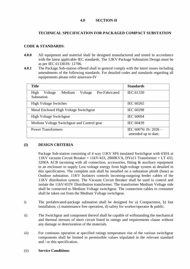
4.0 SECTION-II
TECHNICAL SPECIFICATION FOR PACKAGED COMPACT SUBSTATION
CODE & STANDARDS:
4.0.0 All equipment and material shall be designed manufactured and tested in accordance
with the latest applicable IEC standards. The 12KV Package Substation Design must be
as per IEC 61330/IS: 12786.
4.0.1 The Package Sub-station offered shall in general comply with the latest issues including
amendments of the following standards. For detailed codes and standards regarding all
equipements please refer annexure-IV
Title Standards
High Voltage /Medium Voltage Pre-Fabricated
Substation
IEC:61330
High Voltage Switches IEC 60265
Metal Enclosed High Voltage Switchgear IEC 60298
High Voltage Switchgear IEC 60694
Medium Voltage Switchgear and Control gear IEC 60439
Power Transformers IEC 60076/ IS: 2026 –
amended up to date.
(I) DESIGN CRITERIA
Package Sub-station consisting of 4 way 11KV SF6 insulated Switchgear with 630A at
11KV vacuum Circuit Breaker + 11kV/433, 2000KVA, DYn11 Transformer + LT 433,
3200A ACB incoming with all connection, accessories, fitting & auxiliary equipment
in an enclosure to supply Low-voltage energy from high-voltage system as detailed in
this specification. The complete unit shall be installed on a substation plinth (base) as
Outdoor substation. 11KV Isolators controls incoming-outgoing feeder cables of the
11KV distribution system. The Vacuum Circuit Breaker shall be used to control and
isolate the 11kV/433V Distribution transformer. The transformer Medium Voltage side
shall be connected to Medium Voltage switchgear. The connection cables to consumer
shall be taken out from the Medium Voltage switchgear.
i) The prefabricated-package substation shall be designed for a) Compactness, b) fast
installation, c) maintenance free operation, d) safety for worker/operator & public.
ii) The Switchgear and component thereof shall be capable of withstanding the mechanical
and thermal stresses of short circuit listed in ratings and requirements clause without
any damage or deterioration of the materials.
iii) For continues operation at specified ratings temperature rise of the various switchgear
components shall be limited to permissible values stipulated in the relevant standard
and / or this specification.
(ii) Service Conditions:

The Package substation shall be suitable for continuous operation under the basic service
conditions indicated below
Delhi Atmospheric conditions
i). Average grade atmosphere: Heavily polluted, dry
ii). Maximum altitude above sea
level : 1000 M
iii). Ambient Air temperature: Highest 50 deg C, Average 40 deg C
iv). Design ambient
temperature: 50 deg C
v). Relative Humidity : 90 % Max
vi). Seismic Zone : 4
vii). Rainfall : 750 mm concentrated in four months
The Enclosure of High Voltage switchgear-control gear, Medium Voltage switchgear-control
gear & Transformer of the package substation shall be designed to be used under normal
outdoor service condition as mentioned. The enclosure should take minimum space for the
installation including the space required for approaching various doors & equipment inside.
(II) SPECIFIC REQUIREMENT
The main components of a prefabricated- package substation is Transformer, High-voltage
switchgear-control gear, Low-voltage switchgear-control gear and corresponding
interconnections (copper cable, flexible bus bars) & auxiliary equipment. The components
shall be enclosed, by either common enclosure or by an assembly of enclosure. All the
components shall comply with their relevant IEC standards.
4.1.1 Ratings:
4.1.1.0 Description Value
4.1.1.1
Rated Voltage / Operating
Voltage
11 kV rms
4.1.1.2
Rated frequency & Number of
phases
50Hz & 3Nos.
4.1.1.3
Rated maximum power of
substation
2000 kVA
4.1.1.4
Rated Ingress protection class of
Enclosure
IP-23 for substation enclosure and
IP:54 for LT Switchgear & HT
Switchgear enclosure
4.1.1.5
Rated temp Class of
Transformer Compartment
K20
HV Insulation Level
4.1.1.6
Rated withstand voltage at
power frequency of 50 Hz
28 kV rms
4.1.1.7
Rated Impulse withstand
Voltage
75 kV peak
4.1.1.8 HV Network & Bus bar
4.1.1.9 Rated current 630A
4.1.1.10
Rated short time withstand
current
21 kA rms / 1sec
4.1.1.11 Making capacity for switch- 52.5kA peak

disconnector & earthing
switches
4.1.1.12
Breaking capacity of Isolators
(rated full load)
630A
4.1.1.13 MV PANEL FOR 2000 KVA-
Incomer – 2 nos. 3200A ACB
(EDO Type) microprocessor based
release
Outgoing –
1 No.1250A, ACB (EDO)
1No. 1250A, MCCB (FIXED
3Nos. 630A, MCCB (FIXED)
4.1.1.6 CAPACITOR BANK
(PANEL)
600KVAR
4.2 OUTDOOR ENCLOSURE
4.2.1 The enclosure shall be made of Sheet Steel suited to local weather conditions. Sheet
of minimum 2.5-mm thickness and should be of Monobloc design. The enclosure
shall be tested for internal Arc with stand capacity as per IEC-61330. The enclosure
should not require any artificial cooling through exhaust fans etc. it should be
naturally Air-cooled.
4.2.2 The metal base shall ensure rigidity for easy transport & installation.
4.2.3 The protection degree of the Enclosure shall be IP54 for MV & HT switchgear
compartment & IP23 for Transformer compartment. Proper / adequate
ventilation aperture shall be provided for natural ventilation by way of Louvers etc.
4.2.4 Package Substation should not require any additional civil work at site such as
construction of plinth, platform etc. It should have minimum possible erection time.
4.2.5 Package substation must be delivered in one single indivisible volume to avoid
assembly of components at site.
4.2.6 The doors shall be provided with proper interlocking arrangement for safety of
operator.
4.2.7 The H.V. & M.V. outgoing of the transformer are to be connected to Vacuum Circuit
Breaker of RMU & incomer of the Medium Voltage Switchgear by means of Al.
Cables / Bus bars.
4.2.8 Interconnection: The connection of HT switchgear to Transformer shall be with the
help of suitable size of cables and Transformer to LT switchgear with the help of
suitable size of Copper/ Aluminum bus bars. The interconnection inside the unit shall
be the responsibility of the supplier.
4.2.9 Internal Fault: Failure within the package substation due either to a defect, an
exceptional service condition or mal-operation may initiate an internal arc. Such an
event may lead to the risk of injury, if persons are present. It is desirable that the
highest practicable degree of protection to persons shall be provided. The Design
shall be tested as per IEC 61330.
4.2.10 Covers & Doors: Covers & doors are part of the enclosure. When they are closed,
they shall provide the degree of protection specified for the enclosure. Ventilation
openings shall be so arranged or shielded that same degree of protection as specified
for enclosure is obtained. Additional wire mesh may be used with proper Danger
board for safety of the operator. All covers, doors or roof shall be provided with

locking facility or it shall not be possible to open or remove them before doors used
for normal operation have been opened. The doors shall open outward at an angle of
at least 900
& be equipped with a device able to maintain them in an open position.
4.2.11 There shall be an arrangement for internal lighting activated by associated switch for
HV, Transformer & LV compartments separately.
4.2.12 Labels: Labels for warning, manufacturer’s operating instructions etc. shall be
durable & clearly legible.
4.2.13 Safety notices and faults indicator outside the package substation to indicate any
fault.
4.2.14 The paints shall be carefully selected to withstand tropical heat and rain. The paint
shall not scale off or crinkle or be removed by abrasion due to normal handling.
4.2.15 Earthing: All metallic components shall be earthed to a common earthing point. It
shall be terminated by an adequate terminal intended for connection to the earth
system of the installation, by way of flexible jumpers/strips & Lug arrangement. The
continuity of the earth system shall be ensured taking into account the thermal &
mechanical stresses caused by the current it may have to carry. The components to
be connected to the earth system shall include:
a) The enclosure of Package substation,
b) The enclosure of High voltage switchgear & control gear from the terminal provided
for the purpose, The metal screen & the high voltage cable earth conductor,
c) The transformer tank or metal frame of transformer,
d) The frame & / or enclosure of Medium Voltage switchgear,
4.2.16 Internal Illumination: There shall be arrangement for internal lighting activated by
associated switch on doors for HV, Transformer & LV compartments separately.
4.2.17 Labels: Labels for warning, manufacturer’s operating instructions etc. & those
according to local standards & regulations shall be pasted/ provided inside and
shall be durable & clearly legible.
4.2.18 Painting and Fabrication process
(a) The paints shall be carefully selected to withstand tropical heat & rain. The paint shall
not scale off or crinkle or be removed by abrasion due to normal 55 handling. For this
purpose, poly- urethane (or such other suitable) paint shall be used.
(b) Special care shall be taken by the manufacturer to ensure against rusting of nuts, bolts
and fittings during operation. All bushings and current carrying parts shall be cleaned
properly after final painting.
(c) The fabrication process shall ensure that there are no sharp edges on the GI sheets
used. For modular structure the two smaller units shall be joined together by
Clinching Technology so that is on piercing to the material being joined. This type of
joint shall ensure robust mechanical strength to the complete structure so made.
4.3 RING MAIN UNIT
4.3.0 11KV NON-EXT SF6 RMU WITH VACUUM CIRCUIT BREAKER
SWITCHGEAR:
i) The SF6 RMU shall be Sealed for life, the enclosure shall meet the “sealed pressure
system” criteria in accordance with IEC: 298 (a system for which no handling of gas is
required throughout service life of approximate 25 years.) There shall be no
requirement to ‘top up’ the SF6 gas. In addition, manufacturer shall confirm that
maximum leakage rate is lower than 0.1% per year. It shall provide full insulation,
making the switchgear insensitive to the environment. Thus assembled, the active parts
of the switchgear unit shall be maintenance free.

ii) The switchgear & switchboard shall be designed so that the position of different
devices is visible to the operator on the front of the switchboard & operations are
visible as well. The switchboard shall be designed so as to prevent access to all live
parts during operation without the use of tools.
iii) RMU should be tested for internal arc fault test.
The requirement of 11kv Ring Main Unit is as under.
4.3.1 SF6 Gas filled Non-Extensible Ring Main Units with Load Break Cable Switch and
Vacuum Circuit Breaker comprising of 4panels as indicated below (This is for
reference and by if any standards it is required to be changed may be allowed by OEM)
4.3.2 Panel No.1&4- Load Break Cable Switch/ Isolators: Isolator panel with one number
SF6 insulated load breaking fault making isolator switch with one cable box accessible
from the front. Load Break Cable Switch Load Break Cable Switch with integral earth
switch both having full making capacity shall be used for Incoming and Outgoing
cables if used in a ring. Suitable arc proof tested cable covers shall be provided for each
cable switch. the cable covers accessible from front shall be mechanically interlocked
to its corresponding earth switch shall be mechanically interlocked to its corresponding
cable switch for safety of the operator. The Isolators offered shall conform to
IEC60129. The isolator shall be triple pole, spring assisted, hand operated, and non-
automatic type with quick break contacts. The operating handle shall have three
positions ‘ON’, ‘OFF’ and ‘EARTH’ which shall be clearly marked with suitable
arrangement to padlock in any position. A safety arrangement for locking shall be
provided by which the isolator operation shall be prevented from ‘ON’ position to
‘EARTH’ position or vice versa in a single operation.
4.3.3 Panel No.2&3 – Vacuum Circuit Breaker Vacuum Circuit Breaker shall be used for
distribution network of HT switchgear. Vacuum Circuit Breaker complete with perating
mechanism, self-powered microprocessor based protection relay with associated
Current Transformers shall be used for control and protection of Transformer. The
VCB being fixed type shall be provided with an Isolator in series for isolation purpose
for maintenance. An integral cable earthing switch with full making capacity shall be
provided. The arc proof cable covers accessible from front shall be mechanically
interlocked to the earthing switch, which in turn shall be interlocked to the isolator for
safety to the operator complete with operating mechanism, protection system and one
Number each of cable box accessible from the front.
4.3.4 The above Load Break Cable Switches, vacuum circuit breakers, Bus bars should be
mounted inside a robotically welded sealed for life, stainless steel tank of 3 mm thick
sheet metal. The operating mechanism of the switches and breakers shall be outside the
SF6 tank and accessible from front. The tank should be filled with SF6 gas at adequate
pressure. The degree of protection for gas tank should be IP67. There shall be provision
for filling the SF6 gas at site. Moreover, the Stainless-Steel Gas Tank shall confirm to
the sealed pressure system as per IEC and ensure the gas leakage up to 0.1% per year as
per IEC.
4.3.5 The Unit shall consist 400A Tee-off spring assisted three position, three pole Vacuum
circuit breakers, with integral fault making / dead breaking earth switch. The function
shall be naturally interlocked to prevent the main & earth switch from being switched
‘ON’ at the same time & the CB not allowed to trip in ‘Earth On’ position. The
selection of the main/earth switch lever on the panel, which is allowed to move only if
the main or earth switches in the off position. The lever shall be able to pad locked in
either the main or earth position.
4.3.6 The manual operation of the circuit breaker shall not have an effect on the trip spring.
This should only be discharged under a fault (electrical) trip condition; the following
manual reset operation should recharge the trip spring & reset the CB mechanism in
‘main off’ position.
4.3.7 Locking Arrangement: Suitable padlocking arrangements shall be provided as stated
below
a. CB manual operating handle in the “OFF” position.
b. Each feeder Panel operating handles in ‘Closed’ ‘Open” or ‘Earth’ position.
c. Each isolator operating handle in ‘Closed’, ‘Open’, or ‘Earth’ position
4.3.8 The Vacuum Circuit Breaker is required to control 11 kV/433 volts distribution
Transformer of rating 2000KVA and relay settings shall be selected accordingly.
4.3.9 General Finish: Totally enclosed, metal clad, vermin and dust proof suitable for
tropical climate use as detailed in the specification.
4.3.10 Ratings: The bus bars shall have continuous rating of 630 Amps. The isolator shall
have a continuous rating of 630 Amps; Vacuum Circuit Breaker shall have a
continuous rating of 400 Amps. In accordance with relevant IEC standard.
4.3.1 Breaking & Making Capacity: The isolators shall be capable for breaking rated full
load current. Vacuum Circuit Breaker shall be capable of having rupturing capacity of
21kA symmetrical at 11KV.
4.3.2 Bus bar: Switchgear shall be complete with all connection, bus-bars etc. Copper bus
bars continuous rating shall be 630 Amps. The bus bars should be fully encapsulated by
SF6 gas inside the steel tank.
4.3.3 Protection: The Circuit Breaker shall be fitted with microprocessor based self-powered
relay inside the front cover to avoid any tampering. The same shall be used in
conjunction with suitable Current Transformer and Tripping Coil for fault tripping of
the Circuit Barkers.
4.3.4 Remote Operation: Remote operation of the RMU’s Isolators & Breaker CB shall be
possible using Motors fitted to the operating mechanism (Optional if asked). It shall be
possible to fit the motors either directly in manufacturing plant or on site as & when
required. Installation on site shall be possible.
4.3.5 Cable Box: Cable Termination: Each Cable compartment shall be provided with three
bushings of adequate sizes to terminate the incoming and outgoing 11Kv 3 Core cables.
There shall be enough height (Minimum 450mm) from the base to the mounted
switchgear so that the cables can be bent and taken vertically up to the bushings. The
Cable termination shall be done by Heat Shrinkable Termination method so that
adequate clearances shall be maintained between phases for Termination. Access to all
the cables should be possible form the front of panel. Cable Termination boots shall be
supplied by the switchgear manufacturer
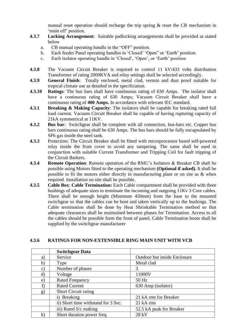
4.3.6 RATINGS FOR NON-EXTENSIBLE RING MAIN UNIT WITH VCB
Switchgear Data
a) Service Outdoor but inside Enclosure
b) Type Metal clad
c) Number of phases 3
d) Voltage 11000V
e) Rated Frequency 50 Hz
f) Rated Current 630 Amp (isolator)
g) Short Circuit rating
i) Breaking 21 kA rms for Breaker
ii) Short time withstand for 3 Sec. 21 kA rms
iii) Rated S/c making 52.5 kA peak for Breaker
h) Short duration power freq. 28 kV

i) Insulation Level 75 kV peak
j) System earthing Solidly earthed at substation
Breaker
a) Type VCB in SF6 tank
b) Rated voltage 11kV
c) Breaking current
i) Load breaking 21 kA rms
d) Making current 52.5 kA peak
e) Rated current 400 Amps.
f) No. of poles 3
g) Operating mechanism. Trip free & free handle type with
mechanically operated indication &
pad locking.
Isolators
a) Type load breaking and fault making in SF6
tank
b) Rated current 630 Amps.
d) Rated breaking capacity 630 Amps.
e) Fault making capacity 52.5 KA peak
f) No. of poles 3
g) Operating mechanism Operating handle with ON, OFF,
Earth positions with arrangement for
padlocking in each position.
Bus bars: (If any)
a) Material Copper
b) Type SF6 insulated
c) Rated Current 630 Amps
d) Short time rating for 3 Sec. -
4.3.7 Testing
Each type of 11Kv Switchgear shall be completely assembled, wired, adjusted and
tested at the factory as per the relevant standards i.e. IS: 9920, IS:3427, IS: 13118, IEC:
265, IEC:298 during manufacturing and on completion
4.3.14 Routine Tests: The tests shall include but not necessarily limited to the following.…
a) Operation under simulated service condition to ensure accuracy of wiring, correctness
of control scheme and proper functioning of the equipment.
b) All wiring and current carrying part shall be given appropriate High Voltage test.
4.4.0 OIL COOLED TYPE DISTRIBUTION TRANSFORMERS
4.4.1 General Construction
The oil filled Transformers shall comply with the following Indian Standards as amended up
to date:
(i) IS 2026 - Part I to V power transformers.
(ii) IS 335 - Transformer oil
(iii) IS 10028 (Part II & III) - Installation and Maintenance of Transformers.
(iv) IS 2099 - Bushings
(v) IS 2705 - Current Transformers.
(vi) IS 6600 - Guide for loading of oil immersed transformers.
4.4.2 Insulation Oil Insulation oil shall conform to IS 335. Transformer oil to be supplied
with initial fill of filtered oil.
4.4.3 General Requirements
The transformer shall be indoor or outdoor type as specified. Unless otherwise specified the
transformer in addition shall have thermal and dynamic ability to withstand external short-
circuit as per clause 9 of IS 2026 (Part I) 1977.
4.4.4 Capacity and Rating.
The KVA ratings for three phase transformers shall be 2000KVA, Continuous rating
specified shall be irrespective of tapping position.
TEMPERATURE RISE
The reference ambient temperatures assumed for the purpose of this specification are as
follows: -
(a) Maximum ambient air temperature 500 C.
(b) Maximum daily average ambient air temperature 400 C.
(c) Maximum yearly weighted average ambient temperature 320 C.
(d) Minimum yearly weighted average ambient temperature (-)50 C.
The temperature rise at the above conditions and at the altitude not exceeding 1000 meters
shall be as follows: -
By resistance method 550 C (maximum temperature being 950 C). By thermometer 500 C. If
the site conditions indicated for a particular job is more severe than the refereed ambient
temperature mentioned above, the temperature rise shall be suitably scaled down such that
the hot spot temperature shall not exceed the values for the reference conditions.
4.4.5 Tap Changing Device
Tap changing device shall be provided on H.V side, circuit type, externally hand operated
with necessary indications for tap position and locking arrangement at any of the tapping
positions. It shall be designed for bi-directional operation and shall be of self-positioning
type and shall have +/-5%
Note: Tap changing device shall normally be off load type.
.
4.4.6 Voltage Ratio
Unless otherwise specified, the transformer shall be suitable for a voltage ratio of 11 KV/433
V.
VECTOR GROUP
In case of step down transformers, the winding connections shall conform to vector group
dyn11 unless otherwise specified. In case of step up transformer the vector group unless
otherwise specified shall be star/ delta.
4.4.7 3.2.7 Cooling
Unless otherwise specified, the transformer shall be oil immersed natural air-cooled type
(ONAN).
4.4.8 Accessories

The transformer shall be a single tank type with termination on bushings or cable end box as
specified both on HV and MV side. The MV side shall be suitable to receive bus bar trunking
or MV cable inter-connection suitable for full load current of the transformer.
FITTINGS
The transformer shall be complete with the following fittings: -
(a) Oil conservator with oil level indicator, minimum level marking and drain plug for all
transformers of capacity 50 KVA and above.
(b) Off circuit type tap changer with position indicator and locking arrangement for all
transformers.
(c) Thermometer pocket with plug for all transformers of capacity 100 KVA and above.
(d) 100 mm dial type /stem type thermometer with metal guard Dial type thermometer may
have max. temperature indicator and resetting device for all transformers of capacity 250
KVA and above.
(e) Lifting lugs for all transformers.
(f) Bi-directional /Unidirectional Rollers to be specified.
(g) Rating diagram and terminal marking plate for all transformers.
(h) Explosion vent for all transformers of capacity 400 KVA and above.
(i) Additional Neutral separately brought out on a bushing for earthing for all transformers.
(j) Earth terminals (2 Nos.) for body earthing for all transformers.
(k) Valves for filtration, drainage and filling etc. with necessary plugs for all transformers.
(l) Radiator assembly for all transformers.
(m) Silica gel breather for all transformers.
(n) Air release plug for all transformers.
(o) First filling of oil to IS 335/1993 including make-up fill during installation for all
transformers.
(p) Facility to connect up Buchholtz relay for all transformers of capacity 800 KVA and
above.
(q) Inspection covers on tank cover for access to terminal connections for all transformers.
(r) Bushing terminations or cable box terminations as specified.
(s) Necessary hardware, clamps, lugs etc. for termination on HV/MV etc. for all
transformers.
4.4.9 Explosion Vent
Explosion vent or pressure relief device shall be provided of sufficient size for rapid release
of any pressure that may be generated within the tank and which might result in damage to
the equipment. The device shall operate at a static pressure less than the hydraulic test
pressure for transformer tank. Means shall be provided to prevent the ingress of moisture and
of such a design to prevent gas accumulation.
4.4.10 Accommodation for Auxiliary Apparatus
Where specified, such as, for restricted earth fault protection, facilities shall be provided for
the mounting of a neutral current transformer.
RATING AND DIAGRAM PLATES
The following plates shall be fixed to Transformer in a visible position.
(a) A rating plate of weather proof material bearing the data specified in the appropriate
clauses of IS: 2026/1977.
(b) A diagram plate showing the internal connection and also the voltage vector relationship
of the several windings in accordance with IS: 2026-1977 and a plan view of the transformer
giving the correct physical relationship of the terminals.
4.4.11 Joints and Gaskets
All gaskets used for making oil tight joints shall be of proven material such as granulated
cork bonded with synthetic rubber gaskets or synthetic rubber or such other good material.
GAS AND OIL ACTUATED (BUCH HOLTZ) RELAYS
Buchholtz Relay shall be provided for transformers of capacity 800 KVA and above. The
design of the relay mounting arrangements, the associated pipe work shall be such that mal-
operation of the relays shall not take place under normal service. The pipe work shall be so
arranged that all gas arising from the transformer shall pass through the gas and oil-actuated
relay. The oil circuit through the relay shall not form a delivery path in parallel with any
circulating oil pipe, nor shall it be tied into or connected through the pressure relief vent,
Sharp bends in the pipe work shall be avoided. All wiring connections, terminal boards, fuses
and links etc. connected with gas actuated relays shall be suitable for tropical atmosphere.
Any wiring liable to be in contact with oil shall have oil resistant insulation and the bared
ends of stranded wire shall be sealed together to prevent seepage of oil entering connection
boxes used for cables or wiring.
4.4.12 3.2.12 Cable Box
Cable box shall not be mounted on the tank covers. It shall be feasible to remove the tank
covers for inspection during maintenance etc. without recourse to breaking the joints or
disturbing the cables already terminated. Necessary removable links in oil approachable
through inspection cover in tank cover etc. after lowering oil shall be provided for test
purpose.
4.4.13 Parallel Operation
For parallel operation of transformers, the transformers shall have the same percentage
impedance, same voltage ratio, same vector group, phase sequence etc.
4.4.14 Tests
4.4.14.1 Tests at Works
All routine and other tests prescribed by IS 2026 shall be carried out at the manufacturer’s
works before dispatch of the transformer in the presence of inspecting officer if required.
Copies of the test certificates shall be furnished to the department. In addition to the
prescribed routine tests, temperature rise test shall be invariably done on one transformer of
each design. A copy of the impulse test certificate done on the same type/ design of the
transformer shall be furnished in accordance with IS for purpose of record. If no impulse test
was done in an earlier unit of the same design and capacity, one transformer will be subjected
to impulse test in consultation with the Inspector at the firm’s cost. Copies of the certificates
for pressure test, test for bushings, and type test for short circuit shall be supplied to the
Department.
4.4.14.2 Tests at Site
In addition to tests at manufacturer’s premises, all relevant precommissioning checks and
tests conforming to IS code of practice No. 10028 (Part II & III) shall be done before
energization. The following tests are to be particularly done before cable jointing or
connecting up the bus bar trunking.
(a) Insulation test between HV to earth and HV to MV with 5000 volts Megger.
(b) Insulation test between MV to earth with 500 volts Megger.
(c) Di-electric strength Test on oil.
(d) Buchholtz relay operation by simulation test when fitted.
All test results are to be recorded and reports should be submitted to the department.
4.4.15 Installation and Commissioning
4.4.15.1 The transformer shall be installed in accordance with IS 10028 (Part II &
III)-Code of practice for Installation and maintenance of transformer.
4.4.15.2 Necessary support channels shall be grouted in the flooring. The Transformer shall be
moved to its location and shall be correctly positioned. Transformer wheels shall be either
locked or provided with wheel stoppers. All parts of the transformers which are supplied
loose, such as conservator, radiator banks, Buchholtz relay, dial thermometer, bushing etc.
shall be fitted on the transformer. Transformer oil supplied in drums shall be topped up into
the transformer after duly testing/filtering up to the correct level required.
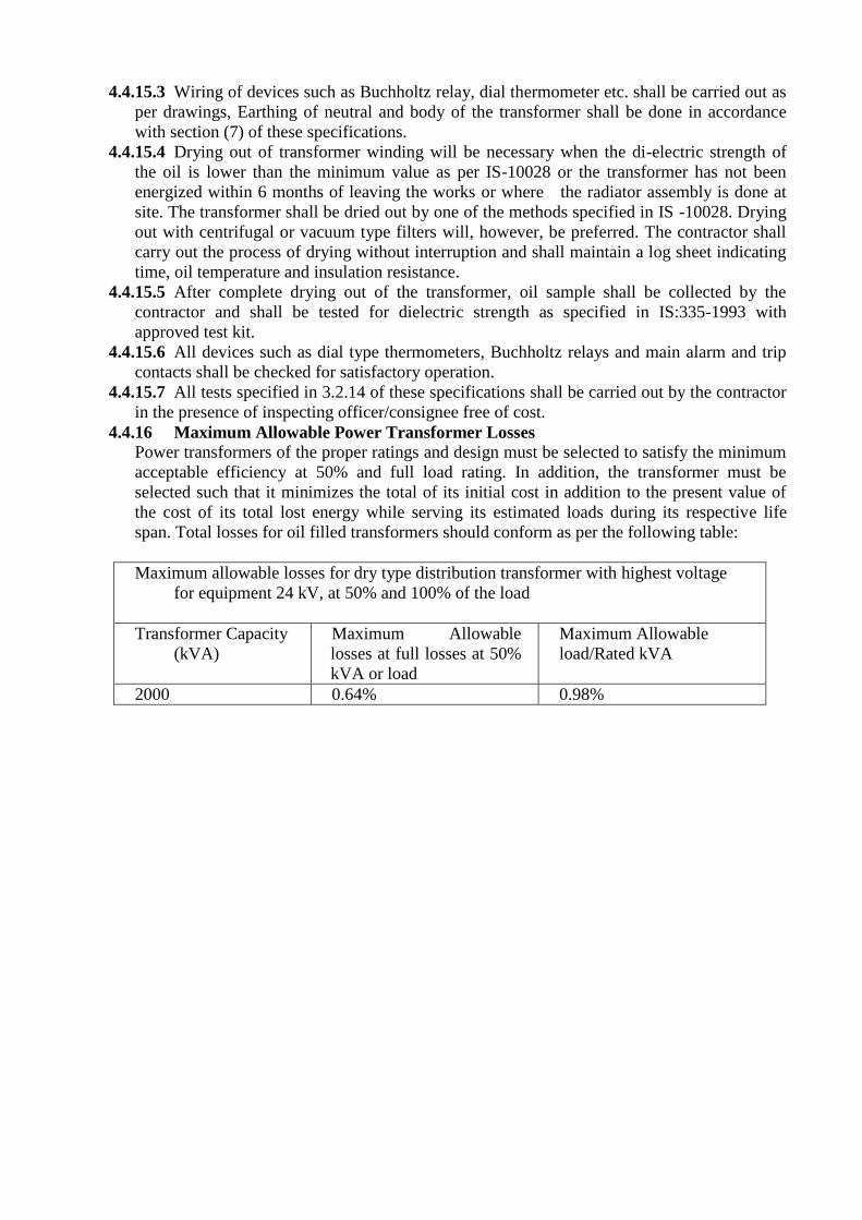
4.4.15.3 Wiring of devices such as Buchholtz relay, dial thermometer etc. shall be carried out as
per drawings, Earthing of neutral and body of the transformer shall be done in accordance
with section (7) of these specifications.
4.4.15.4 Drying out of transformer winding will be necessary when the di-electric strength of
the oil is lower than the minimum value as per IS-10028 or the transformer has not been
energized within 6 months of leaving the works or where the radiator assembly is done at
site. The transformer shall be dried out by one of the methods specified in IS -10028. Drying
out with centrifugal or vacuum type filters will, however, be preferred. The contractor shall
carry out the process of drying without interruption and shall maintain a log sheet indicating
time, oil temperature and insulation resistance.
4.4.15.5 After complete drying out of the transformer, oil sample shall be collected by the
contractor and shall be tested for dielectric strength as specified in IS:335-1993 with
approved test kit.
4.4.15.6 All devices such as dial type thermometers, Buchholtz relays and main alarm and trip
contacts shall be checked for satisfactory operation.
4.4.15.7 All tests specified in 3.2.14 of these specifications shall be carried out by the contractor
in the presence of inspecting officer/consignee free of cost.
4.4.16 Maximum Allowable Power Transformer Losses
Power transformers of the proper ratings and design must be selected to satisfy the minimum
acceptable efficiency at 50% and full load rating. In addition, the transformer must be
selected such that it minimizes the total of its initial cost in addition to the present value of
the cost of its total lost energy while serving its estimated loads during its respective life
span. Total losses for oil filled transformers should conform as per the following table:
Maximum allowable losses for dry type distribution transformer with highest voltage
for equipment 24 kV, at 50% and 100% of the load
Transformer Capacity
(kVA)
Maximum Allowable
losses at full losses at 50%
kVA or load
Maximum Allowable
load/Rated kVA
2000 0.64% 0.98%

4.4.16 GUARANTEED TECHNICAL PARTICULARS FOR TRASFORMER
Sr.No. Descriptions Unit Specification
1 Service Outdoor in an Enclosure Continuous
2 Type Oil filled, core type, step down corrugated tank
Hermitically sealed 3 Rating KVA 2000 4 Rated frequency Hz 50
5 Number of Phase
HV Side 3
LV Side 3
6 Rated Voltage
HV Side kV 11
LV Side kV 0.433
7 Vector Group Dyn11
8 Type of Cooling ONAN
9 Class of Insulations Class F
10 Method of earthing-LV Solidly Earthed
11 Duty Continuous
12 Taps
a) Range % + 5% to -5 %
b) No. of Steps Five
c) In steps, of 2.5
d) Tapping provided on HV Side Taps Provided on HV side
13 Tap Changer Type By Off Circuit Tap Links 14 Temperature
indicator/controller
Oil and winding Temperature indicator
with Contacts to be provided for Alarm
& Tripping. 15 Overload Capability As per IS 6600/IEC 60905
16 Partial Discharge Transformer to be free from partial as
the voltage is reduced from 150 % of
rated voltage i.e. there shall be no
significant rise above background level
17 Reference Standards IS 2026/IS 11171
18 Fittings and Accessories
a) Off circuit tap links Yes
b) 02 Nos. Earthing Terminal Yes
c) Rating and Diagram Plate Yes
d) Lifting Lugs for Complete
Transformer Yes
e) Cover Lifting lugs Yes
f) Rollers Yes
4.4.17 Fittings & Accessories for Corrugated Tank Transformer:
a) The following accessories shall be provided for 11 kV/0.433 kV, 2000kVA distribution
transformer.
b) Two earthing terminals with copper lugs. The lugs shall be provided in such a way that
they shall not obstruct the movements of rollers. The earthing continuity for all the connected
equipments shall be properly done.
c) Two lifting lugs for complete transformer as well as enclosure.
d) Rating plate and diagram plate of durable non-corroding metal giving information as
required under IEC 76. Rating plate shall also include Transformer Actual %Z, No-Load Loss
& Full-Load Loss at 75C along with details like Purchase Order Number, date. The name
plate marking shall be done with fluorescent colour. Each equipment shall carry individual
name-plate with proper instructions & affixed with screws.
e) Four plain rollers fitting so that the transformer can suitably move in any direction along
with roller direction changing and locking facility shall be provided.
f) Instructions & affixed with screws.
g) Skid with Haulage lugs.
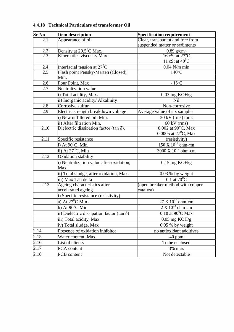
4.4.18 Technical Particulars of transformer Oil
Sr No Item description Specification requirement 2.1 Appearance of oil Clear, transparent and free from
suspended matter or sediments
2.2 Density at 29.50C Max. 0.89 g/cm
3
2.3 Kinematics viscosity Max. 16 cSt at 270C
11 cSt at 400C
2.4 Interfacial tension at 270C 0.04 N/m min
2.5 Flash point Pensky-Marten (Closed), 1400C
Min.
2.6 Pour Point, Max - 150C
2.7 Neutralization value
i) Total acidity, Max. 0.03 mg KOH/g
ii) Inorganic acidity/ Alkalinity Nil
2.8 Corrosive sulfur Non-corrosive
2.9 Electric strength breakdown voltage Average value of six samples
i) New unfiltered oil. Min. 30 kV (rms) min.
ii) After filtration Min. 60 kV (rms) 2.10 Dielectric dissipation factor (tan δ). 0.002 at 90
0C, Max
0.0005 at 270C, Max
2.11 Specific resistance (resistivity)
i) At 900C, Min 150 X 10
12 ohm-cm
ii) At 270C, Min 3000 X 10
12 ohm-cm
2.12 Oxidation stability
i) Neutralization value after oxidation, 0.15 mg KOH/g Max.
ii) Total sludge, after oxidation, Max. 0.03 % by weight
iii) Max Tan delta 0.1 at 700C
2.13 Ageing characteristics after (open breaker method with copper accelerated ageing catalyst)
i) Specific resistance (resistivity)
a) At 270C Min. 27 X 10
12 ohm-cm
b) At 900C Min 2 X 10
12 ohm-cm
ii) Dielectric dissipation factor (tan δ) 0.10 at 900C Max
iii) Total acidity, Max 0.05 mg KOH/g
iv) Total sludge, Max 0.05 % by weight
2.14 Presence of oxidation inhibitor no antioxidant additives
2.15 Water content, Max 40 ppm
2.16 List of clients To be enclosed
2.17 PCA content 3% max
2.18 PCB content Not detectable

4.5.0 L.T. PANEL RATINGS (GUARANTEED TECHNICAL PARTICULARS)
4.5.1 Declared voltage: – 3 Phase, 400V±10% at 50 Hz,
4.5.2 Neutral: – Solidly earthed at substation.
4.5.3 General finish: - Tropical, totally enclosed, metal-clad, weather-proof, vermin and dust
proof.
4.5.4 Construction: Enclosure: - Dead Front type of enclosure shall be able to provide the
degree of Protection IP: 54.
4.5.5 Circuit Ways: Incomer:
3200 A, 4pole, 433V, 50Hz, 50KA, EDO type ACB with Microprocessor based O/L, S/C, E/F release. Rated Insulation Voltage Ui = 1000V, Utilization category = B Qty: 2 sets
Digital Multifunction Meter with A, V, KW, KWH, PF, Cl-0.5 with Port (Conzerv-EM 6400) –
2 Nos. LT Metering CT’s – 3 Nos, 3200/5A, Cast Resin Type, Cl - 0.5, R, Y, B, ON, OFF
LED Indicating Lamps - 5 Nos. Control MCB, 6A, SP – As required
Outgoing: i). 1250 A, 4Pole, 433V, 4pole, 50Hz, 50KA, EDO type ACB with Microprocessor based
O/L, S/C & E/F release. Rated Insulation Voltage Ui = 1000V, Utilization category = B LT Switchgear should be suitable for termination of 3run X 3 ½ C X 240 Sq.mm aluminum armored Cable. R, Y, B, ON, OFF LED Indicating Lamps - 5 Nos. Control MCB, 6A, SP - As required. Qty: 1SET
ii). 1250 A, 433V, 4Pole, 50Hz, 50KA, Fixed manual type MCCB with Microprocessor based O/L,
S/C, E/F release. Rated Insulation Voltage Ui = 1000V, Utilization category = B LT Switchgear
should be suitable for termination of 3run X 3 ½ C X 240 Sq.mm aluminum armored Cable. R, Y, B,
ON, OFF LED Indicating Lamps - 5 Nos. Control MCB, 6A, SP - As required.
Qty: 1SET
iii). 630 A, 433V, 4pole, 50Hz, 35KA, Fixed manual type MCCB with Microprocessor based O/L, S/C & E/F release. Rated Insulation Voltage Ui = 1000V, Utilization category = B LT Switchgear should be suitable for termination of 2runs X 3 ½ C X 240 Sq.mm aluminum armored Cable. R, Y, B, ON, OFF LED Indicating Lamps - 5 Nos. Control MCB, 6A, SP - As required Qty: 3SETs
4.6 SUB STATION FOUNDATION:
Scope involves Supply and erection of compact substation foundation as per the manufacturers
drawing including supply of all the required construction material for execution of civil works
for foundation 2MVA capacity package, required cable trenches for LT and HT cables and all
other sundry materials required in completion whether it is part of schedule or not. Clear height
of the foundation above ground level shall be decided later however it shall never be less than
450mm.

4.7.0 TYPE TESTS FOR THE PACKAGE SUBSTATION COMPLETELY
ASSEMBLED:
4.7.1 Type Test: The Package Substations offered must be type tested as per IEC 61330.
The copy of type test summary should be submitted along with the tender.
4.7.2 Routine Tests: The sequence of routine testing shall be as follows: 1. Visual and dimension check for completely assembled transformer Measurements of
voltage ratio Measurements of winding resistance at principal tap and two extreme taps
2. Vector Group and polarity test
3. Measurements of insulation resistance*
4. Separate sources voltage withstand test.
5. Measurement of iron losses and exciting current at rated frequency and 90%, 100% and
110% rated voltage 6. Induced voltage withstand test.
7. Load losses measurement at 50 % & 100 % of load.
8. Impedance measurement of principal tap (HV and LV) of the transformer.
9. Routine test of tanks
10. Induced voltage withstand test (to be repeated if type tests are conducted).
11. Measurement of Iron loss (to be repeated if type test is conducted).
12. Measurement of capacitance and Tan Delta for Tr. winding and for transformer oil.
13. Ratio of CT
14. Oil leakage test on completely assembled transformer
15. Magnetic balance test
16. Power frequency voltage withstand test on all auxiliary circuits
17. Certification of all test results.
18. Temperature Rise Test #
19. Dissolved gas analysis
20. Calibration of temperature indicators and relays.
a) *Insulation resistance measurement shall be carried out at 5kV for HV and 1kV for LV.
Value of IR should not be less than 1000 M Ohms. Polarization Index (PI
=IR10min/IR1min) should not be less than 1.5 (If one minute IR value is above
5000Mohms and it is not being possible to obtain an accurate 10 minutes reading, in
such cases polarization index can be disregarded as a measure of winding condition.) b) #Temperature rise test may be necessary to be carried one unit/lot. Purchaser’s engineer,
will at its discretion, select transformer for temp. rise test from any lot offered for
inspection at manufacturer's works and witness the same for comparison with
ERDA/CPRI type test results
Test Witness: Routine test as per relevant IEC/IS standards shall be performed in presence
of Owner’s representative for which the Contractor shall give at least fifteen (15) days
advance notice of the date when the tests are to be carried out.
Test Certificates:
Certified reports of all the tests carried out at the works shall be furnished in three (3)
copies for the Owner.
Annexure-I
Submittals required with bid:
i). Completed technical data schedule
ii). Descriptive literature giving full technical details of equipment offered;
iii). Outline dimension drawing for each major component, general arrangement drawing
showing component layout and general schematic diagrams;
iv). Guaranteed Technical Particulars
v). CPRI Type test certificates be enclosed for all type tests applicable as per I.S./ IEC
61330.
vi). Detailed reference list of customers already using equipment offered during the last 5
years with particular emphasis on units of similar design and rating;
vii). Deviations from this specification. Only deviations approved in writing before award of
contract shall be accepted;
viii). Recommended spare parts and consumable items for five years of operation with prices
and spare parts catalogue with price list for future requirements
Annexure-II
Submittals required after award for Approval and subsequent distribution
i). Programme for production and testing
ii). Construction drawing for foundation for the compact sub station
iii). General arrangement drawing for the compact substation and its components -
RMU, LT panel, Transformer and Capacitor panel.
iv). Single line diagrams for RMU, LT panel and Capacitor panel.
v). Control Schematics for- RMU isolators and vacuum circuit breakers, LT EDO Air
circuit breakers and Capacitor panel.
vi). BOM for RMU, LT panel, Transformer and Capacitor panel.
vii). Transport / shipping dimensions with weights, wheel base details, untanking height
etc.
viii). Terminal arrangements and cable box details (A)
ix). List of makes of all fittings and accessories (A)

Annexure-III
Submittals required point prior to dispatch
i). Inspection and test reports carried out in manufacturer’s works
ii). Test certificates of all bought out items
iii). Operation and maintenance Instruction as well as trouble shooting charts/ manual

Annexure-IV
CODES & STANDARDS a) Materials, equipment and methods used in the manufacture of Distribution Transformer
shall conform to the latest edition of below mentioned standards. b) Manufacturer shall possess valid BIS Certification. INDIAN STANDARDS
I: ELECTRO –TECHNICAL VOCABULARY:
IS: 1885 (Part-I) 1961 Fundamental definition
IS: 1885 (Part-VIII) 1986 Secondary cells and batteries (Superseding IS: 1147-1957)
IS: 1885 (Part-X) 1993 Electrical power system protection
IS: 1885 (Part-XI) 1966 Electrical Measurement
IS: 1885 (Part-XVII) 1979 Switchgear and control gear (First revision)
IS: 1885 (Part-XXX) 1971 Overhead transmission and distribution of electrical energy
IS: 1885 (Part-XXXII) 1993 Cables, conductor and accessories for Electrical supply
(Superseding IS: 1591-1960)
IS: 1885 (Part-XXXVIII) 1993 Transformers (First revision)
II: GRAPHICAL SYMBOLS USED IN ELECTRO TECHNOLOGY:
IS: 8270 (Part-I) 1976 Guide for preparation of diagrams, charts &
tables for electro technology. Definitions and
IS: 2032 (Part-I) 1962 Classification (Superseding
IS: 8270 (Part-II) 1976 Item designation
IS: 8270 (Part-III) 1977 General requirements for diagrams
IS: 8270 (Part-IV) 1977 Circuit diagrams
IS: 8270 (Part-V) 1976 Inter connection diagrams and table
III: CONDUCTOR AND POWER CABLES:
IS: 694/1990 PVC insulated cable for working voltages up to and including
1100 volts (Second revision) (Superseding IS: 3035 Part I 1965)
IS:1554 (Part-I)/ 1988 PVC insulate (Heavy duty) working dielectric cables for voltage
up to & i/c. 1100 volts (Second revision)
IS: 1554 (Part II)/1988 For working voltage from 3.3 KV up to and including 11KV
IS:3961 (Part I) 1967 Recommended current ratings for cables: Paper insulated lead
sheathed cables.
IS: 3961 (Part II) 1967 PVC insulated and PVC sheathed heavy duty cables.
IS: 15086 (Part-5). Application guide for nonlinear resistor type Surge arrester for
alternating current system (First revision)
IS: 5819-1970 Recommended short circuit ratings of high voltage PVC cable
IS: 8130/1984 Conductors for insulated electric cables and flexible cords.
IS: 8623 Part I & II/ 1993 Bus bar trunking system (Air insulated &, sandwich insulated
type) IS: IEC 60439-Part I & II
IS 7098-2 (2011): Crosslinked Polyethylene Insulated Thermoplastics Sheathed
Cables
IV: LEECTRICAL INSTALLATION CODE OF PRACTICES:
IS: 10028 (Part-II & III): Installation and maintenance of transformers
IS: 1866/2000 Insulation oil in service, maintenance and supervision code of
practice
1S: IS:3043/1987 Earthing
IS: 13234 Guide for short circuit calculations

IS: 732/1989 Electrical wiring installation (system voltage not exceeding 650 volts)
IS: 1255/1983 Paper insulated power cables (Up to and including 33KV (first revision)
V: SWITHC GEAR AND CONTROL GEAR:
IS: 13947 (Part-I) Degree of protection provided by the (enclosure for Medium
Voltage switchgear and control gear)
IS: 9224 (Part-II) HRC cartridge fuse links up to 650 volts.
IS:13947 (Part -II) Circuit breaker AC requirements & tests for voltages not
exceeding 1000 Volts AC or 1200 volts DC
IS: 13118-1991 General and definition. Section 2- Voltages above 1000 volt AC.
IS: 13118-1991 Type tests & Routine test for voltage above 1000 Volt AC.
IS: 4064 Heavy duty air break switches and composite units of air break
switches & fuses for voltages not exceeding 1000 volts.
IS: 13947 (Part-I) General requirements for switch gear, control gear for voltage
not exceeding 1000 volts.
IS:1000 V AC or 8623/1993 Factory built assemblies of switch gear and control gear for
voltages up to & including 1200 V DC.
IS: 8623 (Part II)/1993 Particular requirements for bus bar trunking system (Bus ways)
IS: 13118-1991 High Voltage alternating current circuit breakers IEC: 60056 63
IS: 9920-2002 High Voltage Switches –Part I: Switches for Rated Voltages
Above I Kv and Less Than 52Kv
IS: 3427-1997 A.C Metal Enclosed Switchgear and Control gear for Rated
Voltages Above I Kv and UP to and Including 52 Kv
IS: 1248 Electrical Measuring Instruments and their Accessories
VI: TRANSFORMERS ANDF REACTORS:
IS: 11171-1985 Dry type power transformer
Power transformer
IS:2026 (Part-I) – 1977: General
IS: 2026 (Part-II)-1977: Temperature rise
IS: 2026 (Part-III)/1981 Insulation level and di-electric tests
IS: 1180/1989 Distribution transformers
IS: 3637/1966 Gas operated relays
IS: 3639/1966 Power transformers fittings and accessories
IS: 6600/1972 Guide for loading of oil immersed transformers
Part I to III IS: 2705/1992 Current transformers
Part I to III IS: 3156/1992 Voltage transformers
IS: 2099/1986: Outdoor type three- phase distribution transformers 64
VII: CHEMECALS:
IS: 5/1994: Colours for ready mixed paints and enamels (Third revision)
IS: 104/1979: Ready mixed paint brushing zinc chrome priming (IInd revision)
IS: 2932/2003 : Enamel, synthetic exterior (a) under coating (b) finishing (Ist
revision)
VIII : INSULATING LIQUIDS :
IS: 6103/1971 : Specific resistance (resistivity) or electrical insulating liquids,
methods of tests for
IS: 6792/1992 : Electric strength of insulating oils, methods for determination of
IS: 335/1993: New insulation oils for transformers and switchgears (2nd
revision)
IS: 15625/2006: Insulating Mats
IX: SAFETY EQUIPMENTS:

IS: 2878/1976: CO2 based Fire Extinguisher
IS: 2171/1976: Chemical based Fire Extinguishers
IS: 15505-2004: HCFC Blend- A Extinguishing System
IS: 15625-2006: Insulating Mats
IEC Standards
IEC 60071 Co-ordination of Insulation.
IEC 60076 Power transformers.
IEC 60044 Current Transformers.
IEC 60214 On Load Tap Changers
IEC 60354 Loading Guide for Oil-Immersed Power Transformers.
IEC 60296 Specification for Unused Mineral Insulating Oils for Transformers
IEC 60156 Method for Determination of the Electric Strength for Insulating Oils.
IEC 60445 Basic& Safety principles for man-machine interface, marking and identification,
Identification of Equipment Terminals and conductor terminals
IEC 60529 Degrees of Protection Provided by Enclosures (IP Code).
IEC 60551 Determination of Transformer and Reactor Sound Levels.
IEC 60606 Application Guide for Power Transformers. IEC 60616 Terminal and Tapping Markings for Power Transformers. IEC 60947 Low-Voltage Switchgear and Control gear.
IEC 60947 Bushing for alternating voltage above 1000V
British Standard
BS 148 Determination of Transformer and Reactor Sound Levels.
BS 223 Application Guide for Power Transformers.
BS 2562 Terminal and Tapping Markings for Power Transformers.
Indian Electricity Rules
Indian Electricity Act
CBIP manual
In the event of direct conflict between various order documents, the precedence of authority of
documents shall be as follows - i. Guaranteed Technical Particulars (GTP) ii. This Specification iii Indian Standards / IEC standards iv Approved Vendor Drawings iv. Other documents
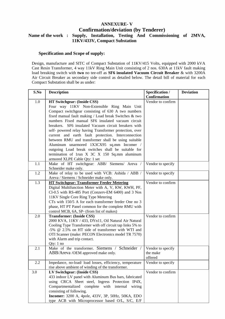
ANNEXURE- V
Confirmation/deviation (by Tenderer) Name of the work : Supply, Installation, Testing And Commissioning of 2MVA,
11KV/433V, Compact Substation
Specification and Scope of supply:
Design, manufacture and SITC of Compact Substation of 11KV/415 Volts, equipped with 2000 kVA Cast Resin Transformer, 4 way 11kV Ring Main Unit consisting of 2 nos. 630A at 11kV fault making load breaking switch with two no tee-off as SF6 insulated Vacuum Circuit Breaker & with 3200A Air Circuit Breaker as secondary side control as detailed below. The detail bill of material for each Compact Substation shall be as under:
S.No Description Specification /
Confirmation
Deviation
1.0 HT Switchgear: (Inside CSS)
Four way 11KV Non-Extensible Ring Main Unit
Compact switchgear consisting of 630 A two numbers
fixed manual fault making / Load break Switches & two
numbers Fixed manual SF6 insulated vacuum circuit
breakers. SF6 insulated Vacuum circuit breakers with
self- powered relay having Transformer protection, over
current and earth fault protection. Interconnection
between RMU and transformer shall be using suitable
Aluminum unarmored 1X3CX95 sq.mm Incomer /
outgoing Load break switches shall be suitable for
termination of 1run X 3C X 150 Sq.mm aluminum
armored XLPE Cable Qty: 1 set
Vendor to confirm
1.1 Make of HT switchgear: ABB/ Siemens/ Areva /
Schneider make only.
Vendor to specify
1.2 Make of relay to be used with VCB: Ashida / ABB / Areva / Siemens / Schneider make only.
Vendor to specify
1.3 HT Switchgear: Transformer Feeder Metering
Digital Multifunction Meter with A, V, KW, KWH, PF,
Cl-0.5 with RS-485 Port (Conzerv-EM 6400) and 3 Nos
11KV Single Core Ring Type Metering
CTs with 150/5 A for each transformer feeder One no 3
phase, HT PT Panel common for the complete RMU with
control MCB, 6A, SP- (from list of makes)
Vendor to confirm
2.0 Transformer: (Inside CSS)
2000 KVA, 11KV / 433, DYn11, Oil Natural Air Natural
Cooling Type Transformer with off circuit tap links 5% to
-5% @ 2.5% on HT side of transformer with WTI and
OTI Scanner (make: PECON Electronics model TR 7570)
with Alarm and trip contact.
Qty: 1 no
Vendor to confirm
2.1 Make of the transformer. Siemens / Schneider / ABB/Areva /OEM approved make only.
Vendor to specify
the make
offered
2.2 Impedance, no-load/ load losses, efficiency, temperature
rise above ambient of winding of the transformer.
Vendor to specify
3.0 LV Switchgear: (Inside CSS)
433 indoor LV panel with Aluminum Bus bars, fabricated
using CRCA Sheet steel, Ingress Protection IP4X,
Compartmentalized complete with internal wiring
consisting of following.
Incomer: 3200 A, 4pole, 433V, 3P, 50Hz, 50KA, EDO
type ACB with Microprocessor based O/L, S/C, E/F
Vendor to confirm

release. Rated Insulation Voltage Ui = 1000V, Utilization
category = B
Qty: 2 sets
3.1 Make of the ACB - Siemens-3WT /ABB/ Schneider make
only.
Vendor to confirm
and specify make
offered
3.2 LV Switchgear: Metering (for Incomers)
Digital Multifunction Meter with A, V, KW, KWH, PF,
Cl-0.5 with Port (Conzerv-EM 6400) – 2 Nos. LT
Metering CT’s – 3 Nos, 3200/5A, Cast Resin Type, Cl -
0.5, R, Y, B, ON, OFF LED Indicating Lamps - 5 Nos.
(Make- Technic/Vaishno/STS/Rep.) Control MCB, 6A,
SP – As required (from approved makes)
Vendor to confirm
3.3 LV Switchgear: Outgoing (Inside CSS)
1250 A, 4pole ,433V, 50Hz, 50KA, EDO type ACB with
Microprocessor based O/L, S/C & E/F release. Rated
Insulation Voltage Ui = 1000V, Utilization category = B
LT Switchgear should be suitable for termination of 3run
X 3 ½ C X 240 Sq.mm aluminum armored Cable. R, Y,
B, ON, OFF LED Indicating Lamps - 5 Nos. (Make-
Vaishno/STS/Rep.) Control MCB, 6A, SP - As required.
(from approved makes)
Qty: 1 set
1250 A, 4pole ,433V, 50Hz, 50KA, Fixed manual type
MCCB with Microprocessor based O/L, S/C, E/F
release. Rated Insulation Voltage Ui = 1000V, Utilization
category = B LT Switchgear should be suitable for
termination of 3run X 3 ½ C X 240 Sq.mm aluminum
armored Cable. R, Y, B, ON, OFF LED Indicating Lamps
- 5 Nos. (Make- Vaishno/STS/Rep.) Control MCB, 6A,
SP - As required.
(from approved makes)
Qty: 1 set
630 A, 4pole ,433V, 50Hz, 35KA, Fixed manual type
MCCB with Microprocessor based O/L, S/C & E/F
release. Rated Insulation Voltage Ui = 1000V, Utilization
category = B LT Switchgear should be suitable for
termination of 2runs X 3 ½ C X 300 Sq.mm aluminum
armored Cable. R, Y, B, ON, OFF LED Indicating Lamps
- 5 Nos. (Make- Vaishno/STS/Rep.) Control MCB, 6A,
SP - As required (from approved makes)
Qty - 3 Nos
Vendor to confirm
4.1 Make of the ACB - Siemens /ABB/ Schneider make only. Vendor to confirm
and specify make
offered
4.2 600KVAR APFC Panel (To be mounted outside the
CSS) for outdoor installation IP 54 protection on
suitable concrete foundation at least 500mm above
ground.
Incomer- 1250 A, 3pole ,433, 3P, 50Hz, 50KA, Fixed
manual type MCCB with Microprocessor based O/L,
S/C, Instantaneous Current & E/F release with 14
Step Single Phase APFC Relay-1 No. (L&T/Neptune /
ABB Make) CT for APFC Relay-1200/5A, Cl-1-1 No.
(Matrix/AE/G&M Make)
Timer- 1no. (GIC/Selectron Make) Control MCB, 6A, SP
Vendor to confirm
and specify make
offered
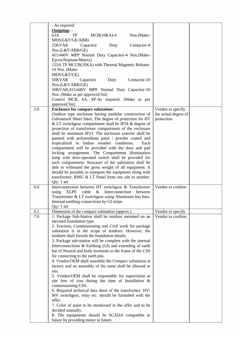
- As required
Outgoing: -
63A TP MCB(10KA)-4 Nos.(Make-
MDS/L&T/GE/ABB)
25KVAR Capacitor Duty Contactor-4
Nos.(L&T/ABB/GE)
415/440V MPP Normal Duty Capacitor-4 Nos.(Make-
Epcos/Neptune/Matrix)
125A TP MCCB(35KA) with Thermal Magnetic Release-
10 Nos. (Make-
MDS/L&T/GE)
50KVAR Capacitor Duty Contactor-10
Nos.(L&T/ABB/GE)
50KVAR,415/440V MPP Normal Duty Capacitor-10
Nos. (Make as per approved list)
Control MCB, 6A, SP-As required. (Make as per
approved list)
5.0 Enclosure for compact substation:
Outdoor type enclosure having modular construction of
Galvanized Sheet Steel. The degree of protection for HT
& LT switchgear compartment shall be IP54 & degree of
protection of transformer compartment of the enclosure
shall be minimum IP23. The enclosure exterior shall be
painted with polyurethane paint / powder coated and
tropicalized to Indian weather conditions. Each
compartment will be provided with the door and pad
locking arrangement. The Compartment illumination
lamp with door-operated switch shall be provided for
each compartment. Structure of the substation shall be
able to withstand the gross weight of all equipment. It
should be possible to transport the equipment along with
transformer, RMU & LT Panel from one site to another.
Qty: 1 set
Vendor to specify
the actual degree of
protection.
6.0 Interconnection between HT switchgear & Transformer
using XLPE cable & Interconnection between
Transformer & LT switchgear using Aluminum bus bars.
Internal earthing connections by GI strips.
Qty: 1 set
Vendor to confirm
6.1 Dimension of the compact substation (approx.) Vendor to specify
7.0 1. Package Sub-Station shall be outdoor mounted on an elevated foundation type.
2. Erection, Commissioning and Civil work for package
substation is in the scope of tenderer. However, the tenderer shall furnish the foundation details.
3. Package sub-station will be complete with the internal
Interconnections & Earthing (GI) and extending of earth
bar of Neutral and body terminals to the frame of the CSS
for connecting to the earth pits.
4. Vendor/OEM shall assemble the Compact substation at
factory and no assembly of the same shall be allowed at
site.
5. Vendor/OEM shall be responsible for supervision at
site free of cost during the time of Installation &
commissioning CSS.
6. Required technical data sheet of the transformer, HV/
MV switchgear, relay etc. should be furnished with the offer.
7. Color of paint to be mentioned in the offer and to be
decided mutually.
8. The equipments should be SCADA compatible in
future by providing motor in future.
Vendor to confirm

9. Vendor shall supply suitable & required no. of HT &
LT Cable termination kits along with CSS for HT & LT
Cable terminations.
8.0 Pre-Dispatch Inspection: Vendor/OEM shall offer for
pre-dispatch inspection at OEM’s works. Only after the
equipments are cleared by IUAC in writing, the
vendor/OEM can dispatch the equipment. Routine tests to
be conducted and original test certificates to be submitted
at the time of PDI.
Vendor to confirm
9.0 Pre- Qualification Requirements
9.1 Refer clause 2(vi) of general terms and conditions at
page-3
Vendor to confirm
& provide
documentary
evidence
9.2 All the pre-qualification requirements should be supported by documentary evidence failing which the
bids will be out rightly rejected.
Vendor to confirm
10.0 Training
10.1 Two IUAC persons shall be trained at OEM’s principles
in the area of
design, maintenance, and operation of Compact
Substation for a period
of 10 working days.
Vendor to confirm
10.1 Air-fare, boarding & lodging for the trainees shall borne
by IUAC.
Vendor to confirm
10.2 Competent, English speaking experts shall be arranged by
the vendor/OEM for satisfactory & effective training of
IUAC personnel.
Vendor to confirm
12.0 Commissioning Spares
12.1 The following additional commissioning spares required -
Digital Multifunction Meter - 1 Nos, Indication lamps-3
Nos, Protection relay – 1 No., Spring Charging handles-2
Nos and Panel Keys – 2 Nos.
Vendor to confirm
13.0 Documentation
13.1 Certified reports of all the tests carried out at the works
shall be furnished in three (3) copies
Vendor to confirm
13.2 Approved Drawings of CSS during pre-dispatch
inspection furnished in three (3) copies shall be
Vendor to confirm
13.3 O&M Manuals of CSS during pre-dispatch inspection
shall be furnished in three (3) copies
Vendor to confirm
14.0 Guarantee
14.1 As per commercial terms and conditions Vendor to confirm
Tenderer is required to select one or more of the make of
items mentioned under S.No. 1.1, 1.2, 1.3, 2.1, 3.1, 3.2,
3.3, 4.0, 4.1, 4.2 & 4.3 In case the Tenderer is offering a
make other than those indicated, the offer is liable for
rejection.
Vendor to confirm
Signature & Seal of Tenderer
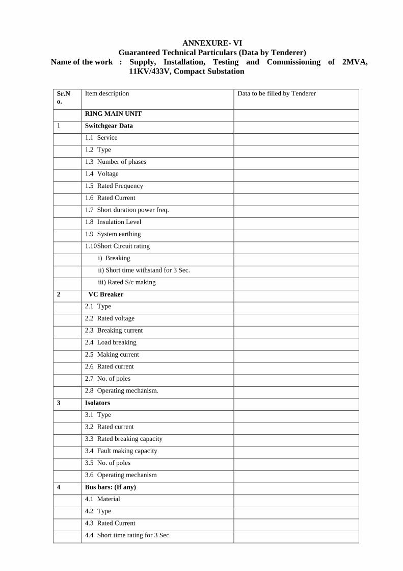
ANNEXURE- VI
Guaranteed Technical Particulars (Data by Tenderer)
Name of the work : Supply, Installation, Testing and Commissioning of 2MVA,
11KV/433V, Compact Substation
Sr.N
o.
Item description Data to be filled by Tenderer
RING MAIN UNIT
1 Switchgear Data
1.1 Service
1.2 Type
1.3 Number of phases
1.4 Voltage
1.5 Rated Frequency
1.6 Rated Current
1.7 Short duration power freq.
1.8 Insulation Level
1.9 System earthing
1.10 Short Circuit rating
i) Breaking
ii) Short time withstand for 3 Sec.
iii) Rated S/c making
2 VC Breaker
2.1 Type
2.2 Rated voltage
2.3 Breaking current
2.4 Load breaking
2.5 Making current
2.6 Rated current
2.7 No. of poles
2.8 Operating mechanism.
3 Isolators
3.1 Type
3.2 Rated current
3.3 Rated breaking capacity
3.4 Fault making capacity
3.5 No. of poles
3.6 Operating mechanism
4 Bus bars: (If any)
4.1 Material
4.2 Type
4.3 Rated Current
4.4 Short time rating for 3 Sec.
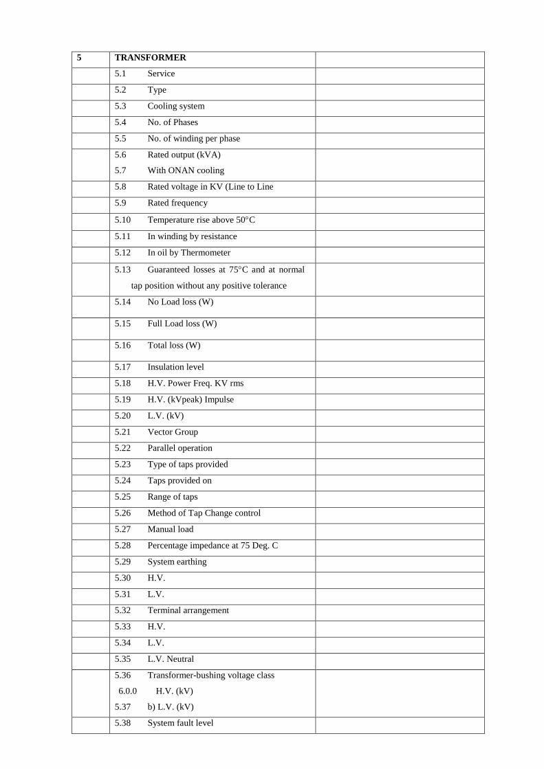
5 TRANSFORMER
5.1 Service
5.2 Type
5.3 Cooling system
5.4 No. of Phases
5.5 No. of winding per phase
5.6 Rated output (kVA)
5.7 With ONAN cooling
5.8 Rated voltage in KV (Line to Line
5.9 Rated frequency
5.10 Temperature rise above 50C
5.11 In winding by resistance
5.12 In oil by Thermometer
5.13 Guaranteed losses at 75C and at normal
tap position without any positive tolerance
5.14 No Load loss (W)
5.15 Full Load loss (W)
5.16 Total loss (W)
5.17 Insulation level
5.18 H.V. Power Freq. KV rms
5.19 H.V. (kVpeak) Impulse
5.20 L.V. (kV)
5.21 Vector Group
5.22 Parallel operation
5.23 Type of taps provided
5.24 Taps provided on
5.25 Range of taps
5.26 Method of Tap Change control
5.27 Manual load
5.28 Percentage impedance at 75 Deg. C
5.29 System earthing
5.30 H.V.
5.31 L.V.
5.32 Terminal arrangement
5.33 H.V.
5.34 L.V.
5.35 L.V. Neutral
5.36 Transformer-bushing voltage class
6.0.0 H.V. (kV)
5.37 b) L.V. (kV)
5.38 System fault level
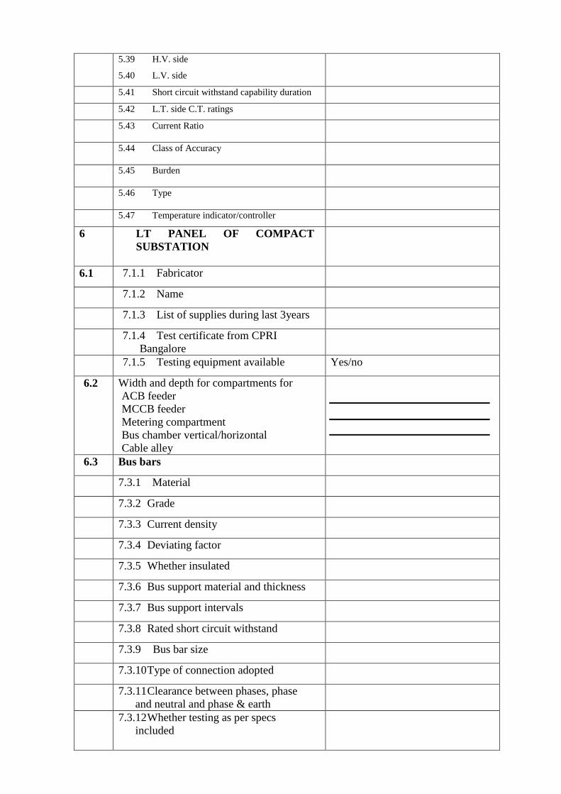
5.39 H.V. side
5.40 L.V. side
5.41 Short circuit withstand capability duration
5.42 L.T. side C.T. ratings
5.43 Current Ratio
5.44 Class of Accuracy
5.45 Burden
5.46 Type
5.47 Temperature indicator/controller
6 LT PANEL OF COMPACT
SUBSTATION
6.1 7.1.1 Fabricator
7.1.2 Name
7.1.3 List of supplies during last 3years
7.1.4 Test certificate from CPRI
Bangalore
7.1.5 Testing equipment available Yes/no
6.2 Width and depth for compartments for
ACB feeder
MCCB feeder
Metering compartment
Bus chamber vertical/horizontal
Cable alley
6.3 Bus bars
7.3.1 Material
7.3.2 Grade
7.3.3 Current density
7.3.4 Deviating factor
7.3.5 Whether insulated
7.3.6 Bus support material and thickness
7.3.7 Bus support intervals
7.3.8 Rated short circuit withstand
7.3.9 Bus bar size
7.3.10 Type of connection adopted
7.3.11 Clearance between phases, phase
and neutral and phase & earth
7.3.12 Whether testing as per specs
included
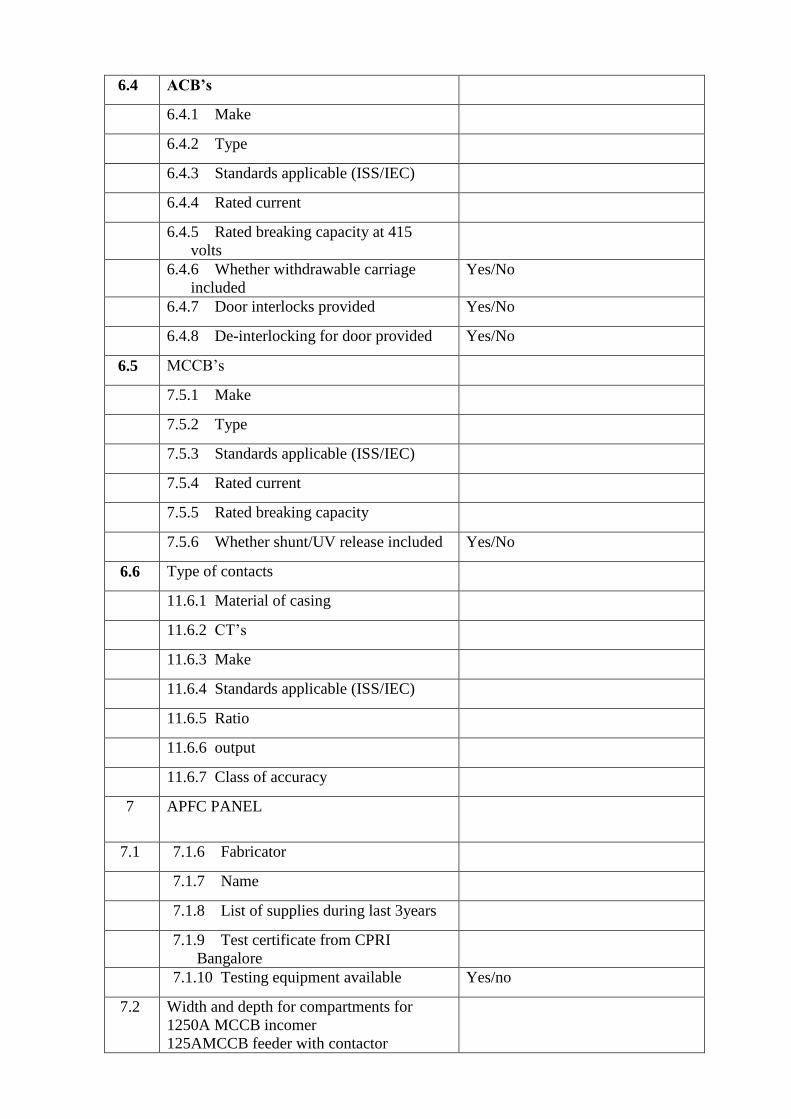
6.4 ACB’s
6.4.1 Make
6.4.2 Type
6.4.3 Standards applicable (ISS/IEC)
6.4.4 Rated current
6.4.5 Rated breaking capacity at 415
volts
6.4.6 Whether withdrawable carriage
included
Yes/No
6.4.7 Door interlocks provided Yes/No
6.4.8 De-interlocking for door provided Yes/No
6.5 MCCB’s
7.5.1 Make
7.5.2 Type
7.5.3 Standards applicable (ISS/IEC)
7.5.4 Rated current
7.5.5 Rated breaking capacity
7.5.6 Whether shunt/UV release included Yes/No
6.6 Type of contacts
11.6.1 Material of casing
11.6.2 CT’s
11.6.3 Make
11.6.4 Standards applicable (ISS/IEC)
11.6.5 Ratio
11.6.6 output
11.6.7 Class of accuracy
7 APFC PANEL
7.1 7.1.6 Fabricator
7.1.7 Name
7.1.8 List of supplies during last 3years
7.1.9 Test certificate from CPRI
Bangalore
7.1.10 Testing equipment available Yes/no
7.2 Width and depth for compartments for
1250A MCCB incomer
125AMCCB feeder with contactor

63A MCCB Feeder with contactor
50KVAR capacitor feeder
25KVAR capacitor feeder
Metering compartment
Bus chamber vertical/horizontal
Cable alley for incomer
7.3 Bus bars
7.3.1 Material
7.3.2 Grade
7.3.3 Current density
7.3.4 Deviating factor
7.3.5 Whether insulated
7.3.6 Bus support material and thickness
7.3.7 Bus support intervals
7.3.8 Rated short circuit withstand
7.3.9 Bus bar size
7.3.10 Clearance between phases, phase
and neutral and phase & earth
7.3.11 Whether testing as per specs
included
7.4 MCCB’s
7.5.1 Make
7.5.2 Type
7.5.3 Standards applicable (ISS/IEC)
7.5.4 Rated current
7.5.5 Rated breaking capacity
7.4 Capacitor duty contactors
7.5.6 Make
7.5.7 Type
7.5.8 Standards applicable (ISS/IEC)
7.5.9 Rated current
7.5.10 Rated breaking capacity
7.4 Normal duty Capacitor
7.5.11 Make
7.5.12 Type
7.5.13 Standards applicable (ISS/IEC)

7.5.14 Rated current
7.5.15 Rated breaking capacity
7.4 APFC RELAY
7.5.16 Make
7.5.17 Type
Guaranteed Technical Particulars of Transformer Oil (Data by Tenderer)
Sr No Item description Specification requirement Data by Vendor
1 Manufacturer Name
1.1 Address
1.2 Contact person
1.3 Contact telephone no 2 Appearance of oil Clear, transparent and free Yes / No
from suspended matter or
sediments
3 Density at 29.50C Max. 0.89 g/cm
3
4 Kinematics viscosity Max. 16 cSt at 270C
11 cSt at 400C
5 Interfacial tension at 270C 0.04 N/m min
6 Flash point Pensky-Marten 1400C
(Closed), Min.
7 Pour Point, Max - 150C
8 Neutralization value
i) Total acidity, Max. 0.03 mg KOH/g
ii) Inorganic acidity/ Alkalinity Nil
9 Corrosive sulfur Non-corrosive
10 Electric strength breakdown Average value of six samples
voltage
i) New unfiltered oil. Min. 30 kV (rms) min.
ii) After filtration Min. 60 kV (rms)
11 Dielectric dissipation factor 0.002 at 900C, Max
(tan δ). 0.0005 at 270C, Max
12 Specific resistance (resistivity)
i) At 900C, Min 150 X 10
12 ohm-cm
ii) At 270C, Min 3000 X 10
12 ohm-cm
13 Oxidation stability
i) Neutralization value after 0.15 mg KOH/g
oxidation, Max.
ii) Total sludge, after 0.03 % by weight
oxidation, Max.
iii) Max Tan delta 0.1 at 700C
14 Ageing characteristics after (open breaker method with
accelerated ageing copper catalyst)
i) Specific resistance
(resistivity)
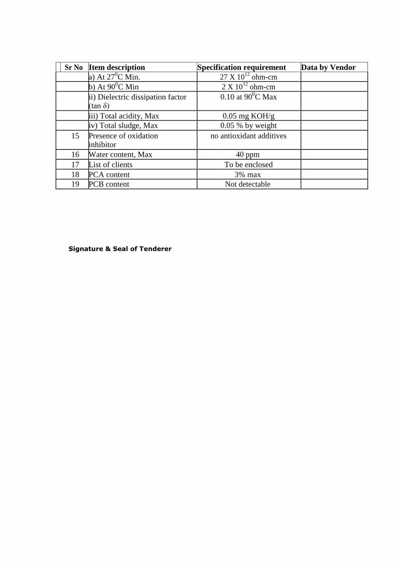
Sr No Item description Specification requirement Data by Vendor
a) At 270C Min. 27 X 10
12 ohm-cm
b) At 900C Min 2 X 10
12 ohm-cm
ii) Dielectric dissipation factor 0.10 at 900C Max
(tan δ)
iii) Total acidity, Max 0.05 mg KOH/g
iv) Total sludge, Max 0.05 % by weight
15 Presence of oxidation no antioxidant additives
inhibitor
16 Water content, Max 40 ppm
17 List of clients To be enclosed
18 PCA content 3% max
19 PCB content Not detectable
Signature & Seal of Tenderer

Annexure VII
Recommended Spares (Data by Tenderer)
Name of the work : Supply, Installation, Testing and Commissioning of 2MVA, 11KV/433V,
Compact Substation
List of recommended spares as following –
Sr. No Description of spare
Part Unit Quantity
Signature & Seal of Tenderer

Annexure VIII LIST OF APPROVED MAKES
S. No Item description Make
1. Compact substation Siemens/Schneider/ABB/AREVA
2. HT Switchgear Siemens / Schneider / ABB /AREVA
3. LT Switchgear Siemens / Schneider / ABB
4. Transformer Siemens / Schneider / ABB/Areva or as per
OEM of Compact substation
5. Bushings Baroda Bushing/CJI/Jaipur
6. Tap changer Alwaye /Paragon
7. Valves Newman
8. Transformer oil Apar/Savita/Raj
9. CRGO Nippon/JFE/Posco/
10. Copper Birla copper/Sterlite
11. Radiators CTR/Hi-Tech Radiators /Tarang Engineers
12. Corrugated Tank MPP/Reputed make
13. ACBs/MCCBs Siemens / Schneider / ABB
14. Make of relay to be used with VCB
Ashida / ABB / Areva / Siemens / Schneider
15. LT CT’s
Siemens / Schneider / ABB / Pragati / ECS /
Kappa or as per OEM of Compact substation
16. HT Cable CCI/Industrial Cable/NICCO/Gloster/Incab
17. Capacitors
L&T/Siemens/Herodex/GE Power
Control/ABB/ Thai cap/EPCOS/NEPTUNE/
18. APFC relay L&T/Neptune / ABB Make
19. Current Transformer AE / Kappa
20. Instruments/meters AE / Rishab/Secure
21. Multi-function meters Siemens/Schneider/ABB or equivalent
22. H.T. Cable Termination Raychem / M Seal / 3M Birla
23. L.T. Cable
gland(single/double)
Comet/Diamond
24. Indication lights BCH / Siemens / L&T / Concord
25. Selector switch L&T / Kaycee
26. Push button L&T / Siemens
27. Terminal strip Connect Well / Elmex
28. Steel /PVC Conduit BEC/AKG/ATUL/STEEL KRAFT/RKG/
SETIA
29. PVC insulated 1.1KV grade
copper wires
National/Ralison/RKG/Finolex/Polycab/
Havells/Kalinga / Lapp cable/ L&T/ Skytone
30. LT XLPE Aluminium
Armoured Cables up to 1100v
Plaza/Skytone/
National/Ralison/PYTEX/Paragon/
KEI/Gloster/CCI
31. MS RACEWAY MURPHY/SLOTCO/REECO/ALER
ON/CUSTAMISED

SCHEDULE OF PRICES
Name of the work : Supply, Installation, Testing and Commissioning of 2MVA, 11KV/433V,
Compact Substation
Abstract of Cost
Heads Amount
Sub Head – I (Equipments) ------------------
Sub Head – II (Cabling) ------------------
Sub Head- III (Earthing) ------------------
Sub Head – IV (Safety Equipment) ------------------
Total _________________
Signature & Seal of Tenderer
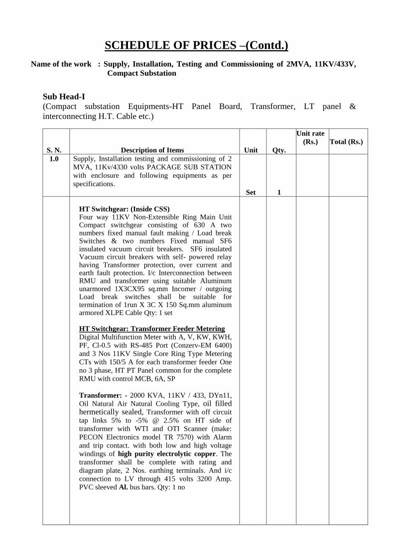
SCHEDULE OF PRICES –(Contd.)
Name of the work : Supply, Installation, Testing and Commissioning of 2MVA, 11KV/433V,
Compact Substation
Sub Head-I
(Compact substation Equipments-HT Panel Board, Transformer, LT panel &
interconnecting H.T. Cable etc.)
S. N. Description of Items Unit Qty.
Unit rate
(Rs.)
Total (Rs.)
1.0 Supply, Installation testing and commissioning of 2
MVA, 11Kv/4330 volts PACKAGE SUB STATION
with enclosure and following equipments as per
specifications.
Set 1
HT Switchgear: (Inside CSS) Four way 11KV Non-Extensible Ring Main Unit Compact switchgear consisting of 630 A two numbers fixed manual fault making / Load break Switches & two numbers Fixed manual SF6 insulated vacuum circuit breakers. SF6 insulated Vacuum circuit breakers with self- powered relay having Transformer protection, over current and earth fault protection. I/c Interconnection between RMU and transformer using suitable Aluminum unarmored 1X3CX95 sq.mm Incomer / outgoing Load break switches shall be suitable for termination of 1run X 3C X 150 Sq.mm aluminum armored XLPE Cable Qty: 1 set HT Switchgear: Transformer Feeder Metering
Digital Multifunction Meter with A, V, KW, KWH,
PF, Cl-0.5 with RS-485 Port (Conzerv-EM 6400)
and 3 Nos 11KV Single Core Ring Type Metering
CTs with 150/5 A for each transformer feeder One
no 3 phase, HT PT Panel common for the complete
RMU with control MCB, 6A, SP
Transformer: - 2000 KVA, 11KV / 433, DYn11,
Oil Natural Air Natural Cooling Type, oil filled hermetically sealed, Transformer with off circuit
tap links 5% to -5% @ 2.5% on HT side of
transformer with WTI and OTI Scanner (make:
PECON Electronics model TR 7570) with Alarm
and trip contact. with both low and high voltage
windings of high purity electrolytic copper. The
transformer shall be complete with rating and
diagram plate, 2 Nos. earthing terminals. And i/c
connection to LV through 415 volts 3200 Amp.
PVC sleeved Al. bus bars. Qty: 1 no

S. N. Description of Items Unit Qty.
Unit rate
(Rs.)
Total (Rs.)
L.T. Panel: 1No LT Panel with following
switchgears and protections
INCOMER:
3200 A, 4pole, 433V, 50Hz, 50KA, EDO type ACB
with Microprocessor based O/L, S/C, E/F release.
Rated Insulation Voltage Ui = 1000V, Utilization
category = B Digital Multifunction Meter with A,
V, KW, KWH, PF, Cl-0.5 with Port (Conzerv-EM
6400) – 2 Nos. LT Metering CT’s – 3 Nos,
3200/5A, Cast Resin Type, Cl - 0.5, R, Y, B, ON,
OFF LED Indicating Lamps - 5 Nos. Control MCB,
6A, SP
Qty: 2 sets
OUTGOING
(a) 1250 A, 4pole ,433V, 50Hz, 50KA, EDO type
ACB with Microprocessor based O/L, S/C &
E/F release. Rated Insulation Voltage Ui = 1000V,
Utilization category = B LT Switchgear should be
suitable for termination of 3run X 3 ½ C X 240
Sq.mm aluminum armored Cable. R, Y, B, ON,
OFF LED Indicating Lamps - 5 Nos. (Make-
Vaishno/STS/Rep.) Control MCB, 6A, SP - As
required.
Qty: 1 set
(b) 1250 A, 4pole ,433V, 50Hz, 50KA, Fixed
manual type MCCB with Microprocessor based
O/L, S/C, E/F release. Rated Insulation Voltage
Ui = 1000V, Utilization category = B LT
Switchgear should be suitable for termination of
3run X 3 ½ C X 240 Sq.mm aluminum armored
Cable. R, Y, B, ON, OFF LED Indicating Lamps -
5 Nos. Control MCB, 6A, SP - As required.
Qty: 1 set
(c) 630 A, 4pole ,433V, 50Hz, 35KA, Fixed manual
type MCCB with Microprocessor based O/L, S/C
& E/F release. Rated Insulation Voltage Ui =
1000V, Utilization category = B LT Switchgear
should be suitable for termination of 2runs X 3 ½
C X 300 Sq.mm aluminum armored Cable. R, Y,
B, ON, OFF LED Indicating Lamps - 5 Nos.
Control MCB, 6A, SP - As required
Qty - 3 Nos
2. Supply, Installation testing and commissioning of
600KVAR APFC Panel (To be mounted outside the
CSS) for outdoor installation IP 54 protection on
suitable concrete foundation at least 500mm above
ground. I/c supply and making foundation structure. Incomer- 1250 A, 3pole ,433, 3P, 50Hz, 50KA, Fixed manual type MCCB with Microprocessor based O/L, S/C, Instantaneous Current & E/F release with 14 Step Single Phase APFC Relay-1 No CT for APFC Relay-1200/5A, Cl-1-1 No Set 1
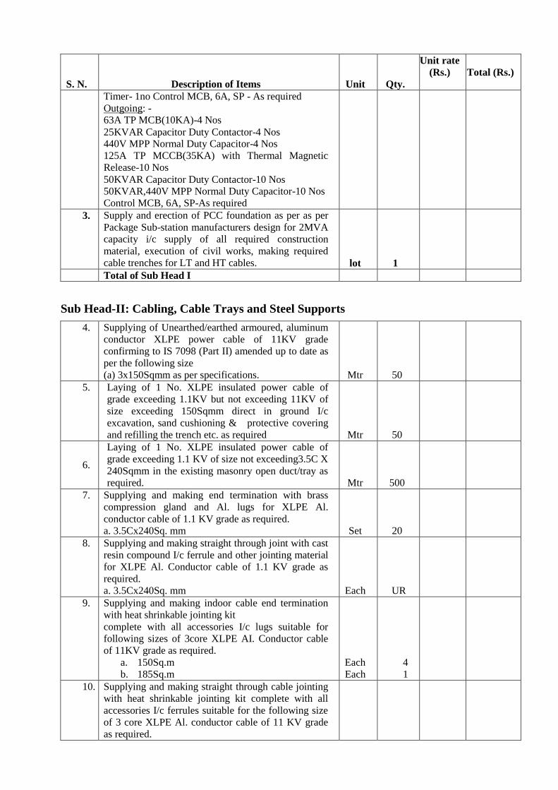
S. N. Description of Items Unit Qty.
Unit rate
(Rs.)
Total (Rs.)
Timer- 1no Control MCB, 6A, SP - As required
Outgoing: - 63A TP MCB(10KA)-4 Nos
25KVAR Capacitor Duty Contactor-4 Nos 440V MPP Normal Duty Capacitor-4 Nos
125A TP MCCB(35KA) with Thermal Magnetic
Release-10 Nos
50KVAR Capacitor Duty Contactor-10 Nos 50KVAR,440V MPP Normal Duty Capacitor-10 Nos
Control MCB, 6A, SP-As required
3. Supply and erection of PCC foundation as per as per
Package Sub-station manufacturers design for 2MVA
capacity i/c supply of all required construction
material, execution of civil works, making required
cable trenches for LT and HT cables. lot 1
Total of Sub Head I
Sub Head-II: Cabling, Cable Trays and Steel Supports
4. Supplying of Unearthed/earthed armoured, aluminum
conductor XLPE power cable of 11KV grade
confirming to IS 7098 (Part II) amended up to date as
per the following size
(a) 3x150Sqmm as per specifications. Mtr 50
5. Laying of 1 No. XLPE insulated power cable of
grade exceeding 1.1KV but not exceeding 11KV of
size exceeding 150Sqmm direct in ground I/c
excavation, sand cushioning & protective covering
and refilling the trench etc. as required Mtr 50
6.
Laying of 1 No. XLPE insulated power cable of
grade exceeding 1.1 KV of size not exceeding3.5C X
240Sqmm in the existing masonry open duct/tray as
required. Mtr 500
7. Supplying and making end termination with brass
compression gland and Al. lugs for XLPE Al.
conductor cable of 1.1 KV grade as required.
a. 3.5Cx240Sq. mm Set 20
8. Supplying and making straight through joint with cast
resin compound I/c ferrule and other jointing material
for XLPE Al. Conductor cable of 1.1 KV grade as
required.
a. 3.5Cx240Sq. mm Each UR
9. Supplying and making indoor cable end termination
with heat shrinkable jointing kit
complete with all accessories I/c lugs suitable for
following sizes of 3core XLPE AI. Conductor cable
of 11KV grade as required.
a. 150Sq.m
b. 185Sq.m
Each
Each
4
1
10. Supplying and making straight through cable jointing
with heat shrinkable jointing kit complete with all
accessories I/c ferrules suitable for the following size
of 3 core XLPE Al. conductor cable of 11 KV grade
as required.
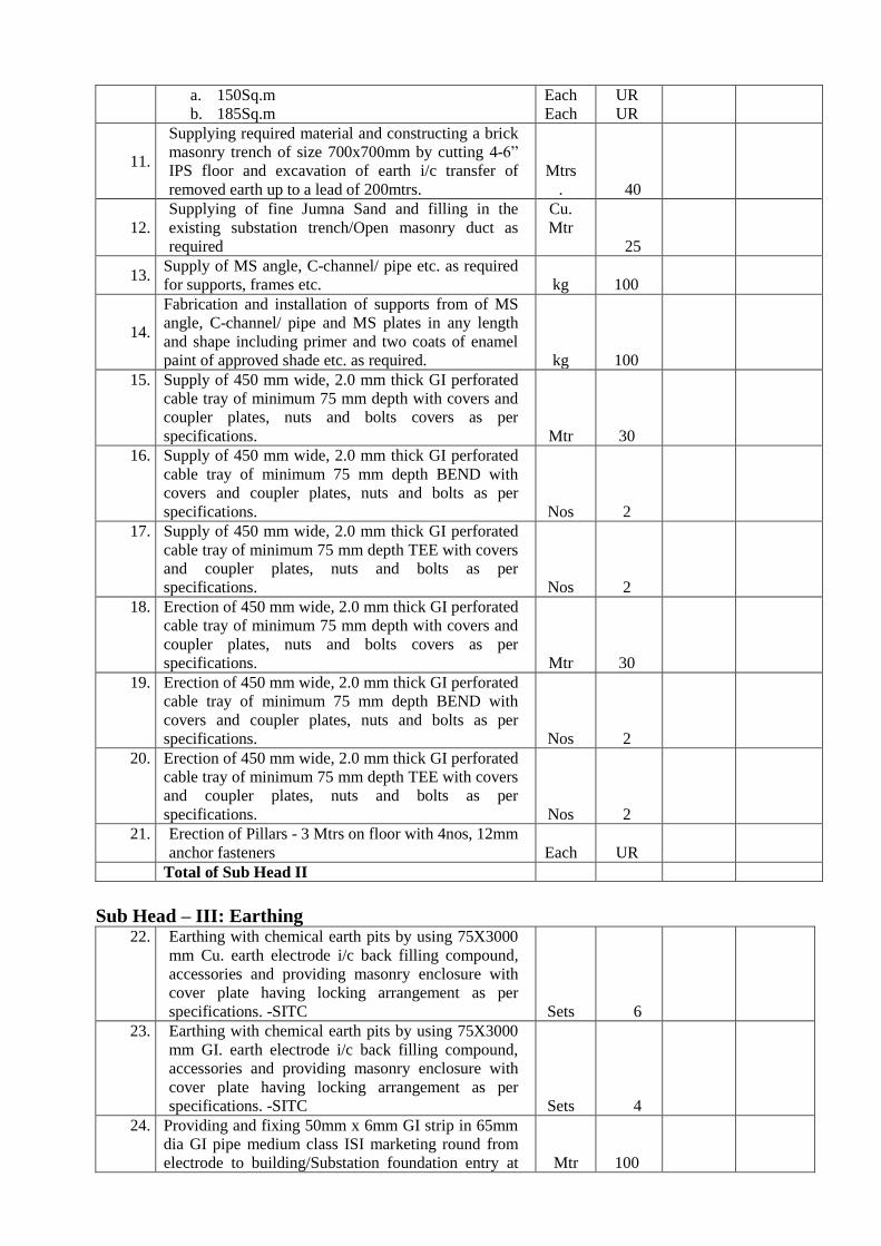
a. 150Sq.m
b. 185Sq.m
Each
Each
UR
UR
11.
Supplying required material and constructing a brick
masonry trench of size 700x700mm by cutting 4-6”
IPS floor and excavation of earth i/c transfer of
removed earth up to a lead of 200mtrs.
Mtrs
. 40
12. Supplying of fine Jumna Sand and filling in the
existing substation trench/Open masonry duct as
required
Cu.
Mtr
25
13. Supply of MS angle, C-channel/ pipe etc. as required
for supports, frames etc. kg 100
14.
Fabrication and installation of supports from of MS
angle, C-channel/ pipe and MS plates in any length
and shape including primer and two coats of enamel
paint of approved shade etc. as required. kg 100
15. Supply of 450 mm wide, 2.0 mm thick GI perforated
cable tray of minimum 75 mm depth with covers and
coupler plates, nuts and bolts covers as per
specifications. Mtr 30
16. Supply of 450 mm wide, 2.0 mm thick GI perforated
cable tray of minimum 75 mm depth BEND with
covers and coupler plates, nuts and bolts as per
specifications. Nos 2
17. Supply of 450 mm wide, 2.0 mm thick GI perforated
cable tray of minimum 75 mm depth TEE with covers
and coupler plates, nuts and bolts as per
specifications. Nos 2
18. Erection of 450 mm wide, 2.0 mm thick GI perforated
cable tray of minimum 75 mm depth with covers and
coupler plates, nuts and bolts covers as per
specifications. Mtr 30
19. Erection of 450 mm wide, 2.0 mm thick GI perforated
cable tray of minimum 75 mm depth BEND with
covers and coupler plates, nuts and bolts as per
specifications. Nos 2
20. Erection of 450 mm wide, 2.0 mm thick GI perforated
cable tray of minimum 75 mm depth TEE with covers
and coupler plates, nuts and bolts as per
specifications. Nos 2
21. Erection of Pillars - 3 Mtrs on floor with 4nos, 12mm
anchor fasteners Each UR
Total of Sub Head II
Sub Head – III: Earthing 22. Earthing with chemical earth pits by using 75X3000
mm Cu. earth electrode i/c back filling compound,
accessories and providing masonry enclosure with
cover plate having locking arrangement as per
specifications. -SITC Sets 6
23. Earthing with chemical earth pits by using 75X3000
mm GI. earth electrode i/c back filling compound,
accessories and providing masonry enclosure with
cover plate having locking arrangement as per
specifications. -SITC Sets 4
24. Providing and fixing 50mm x 6mm GI strip in 65mm
dia GI pipe medium class ISI marketing round from
electrode to building/Substation foundation entry at Mtr 100

depth of 600mm as required
25. Providing and fixing 50mm x 6mm Cu strip in 65mm
dia GI pipe medium class ISI marketing round from
electrode to building/Substation foundation entry at
depth of 600mm as required Mtr 200
26. Providing and fixing earth bus of 50mm x 6mm GI
strip on surface for connection etc. as required. Mtr 20
27. Providing and fixing earth bus of 50mm x 6mm
Copper strip on surface for connection etc. as
required. Mtr 40
28. Providing and fixing 75 mm x 6 mm copper strip on
surface or in recess from earth electrode to all the
substation components etc. as required. Mtr UR
29. Providing and fixing /securing, insulated with heat
shrink sleeve, 75 mm x 3.0 mm copper strip (single
roll in length minimum 25 mtrs) as required. Mtr 200
30. Exothermic welding/ brazing Cu. strip to
electrode/Cu. Strip. Nos. 20
31. Riveting sweating & soldering of copper strip with
another copper strip or any other metallic object as
required. Nos. 20
Total of Sub Head III
Sub Head – IV: Safety Equipment
32. Providing & fixing danger plates made of mild steel
at least 2mm thick & vitreous enameled white on both
sides & with inscriptions in signal red colour on front
side as read.
a. High Voltage- size 250mm x 200mm
b. Medium Voltage – size 200mm x 150mm
Each
Each
UR
UR
33. Providing and fixing carbon dioxide (CO2) type fire
extinguishers confirming to IS 2878-1976 and
cylinders fully charged of following capacity.
(a) 4.5KG Each
UR
34. Providing and fixing of foam fire extinguishers,
Portable type 9 lit capacity hanged on wall with
bracket complete as required Each
UR
35. Providing of set of 4 Nos. 9.5 Litre capacity GI
bucket painted in post office red colour with prior
coat of red oxide paint and written with white paint
‘FIRE’ and mounted on MS angle iron frame with
bracket of appropriate size & capacity I/c filling sand
etc. Set
1
36. Fixing of Safety charts, shock treatment charts, HT,
MV danger plates, first aid boxes as per CPWD
specifications (Part-IV) Set 1
Total of Sub Head IV
Signature & Seal of Tenderer