tender document for fabrication, …i... · 6.5.1. testing the equipments at site ... high heat...
TRANSCRIPT

TENDER DOCUMENT FOR FABRICATION,
INSTALLATION, COMMISSIONING AND TESTING
OF HIGH PRESSURE HIGH TEMPERATURE
CLOSED LOOP WATER CIRCULATION SYSTEM
FOR HIGH HEAT FLUX TEST FACILITY
INSTITUTE FOR PLASMA RESEARCH
BHAT, GANDHINAGAR,
GUJARAT – 382428
1
CONTENTS
1. INTRODUCTION....................................................................................................... 3
2. DESCRIPTION ........................................................................................................... 3
2.1. Operating parameters at the inlet of test section ....................................................... 4
2.2. Details of proposed design........................................................................................... 4
3. TECHNICAL SPECIFICATIONS............................................................................. 4
3.1. Basis of design.............................................................................................................. 4
3.2. Site condition ............................................................................................................... 4
3.3. Design Concept ............................................................................................................ 5
3.4. System Components .................................................................................................... 5
4. OPERATING PROCEDURE ..................................................................................... 9
5. DATA ACQUISITION AND CONTROL SYSTEM ............................................... 10
6. VENDORS SCOPE OF WORK ............................................................................... 13
6.1. Validation of proposed Engineering design.............................................................. 14
6.2. Operation and control system specifications ............................................................ 14
6.3. Selection & procurement of material........................................................................ 16
6.4. Fabrication & assembly ............................................................................................ 16
6.5. Inspection & Testing ................................................................................................. 16
6.5.1. Testing the equipments at Site............................................................................ 17
6.5.2. Pre -dispatch Inspection & Testing at Vendors site........................................... 17
6.5.3. Test Certificates .................................................................................................. 19
2
7. COMPLETION OF ERECTION & COMMISSIONING....................................... 20
8. ACCEPTANCE CRITERIA..................................................................................... 20
9. DELIVERABLES...................................................................................................... 20
10. QUALITY CONTROL AND ASSURANCE TEST................................................. 21
11. GUARANTEE ........................................................................................................... 21
12. SAFETY..................................................................................................................... 22
13. GENERAL TERMS AND CONDITIONS ............................................................... 22
14. EXPECTATION FROM VENDORS ....................................................................... 22
15. COMPLETION PERIOD ......................................................................................... 22
16. BAR CHART/ PROJECT SCHEDULE & PERIODICAL PREVIEW.................. 22
17. DRAWINGS .............................................................................................................. 23
ANNEXURE-1 (List of Drawings).................................................................................... 24
ANNEXURE-2 (Technical Specifications) ....................................................................... 30
ANNEXURE 3 (List of Approved make) ......................................................................... 37
ANNEXURE 4 (List of BIS & ASME Codes) ................................................................. 39
ANNEXURE 5 (Quality Assurance Plan)…………………………………………………42
ABBREVATIONS............................................................................................................. 52

3
1. INTRODUCTION
Institute for Plasma Research (IPR) is working on developing various technologies based on
Tokamaks for future fusion power plants. Fusion power plants often encounter high heat
fluxes due to the high temperature plasma produced. High heat flux (HHF) testing is used to
test the integrity of various materials developed for withstanding these high heat fluxes. The
test mock –ups / components (loads) inside the HHF test facility is connected to water
circulation system which is expected to circulate water at high pressure in the range of 5 bar -
60 bar, high temperatures in the range of 25oC - 160oC and flow- rate up to 300 LPM. The
test mock – up or components to be tested will have typical internal diameters in the range of
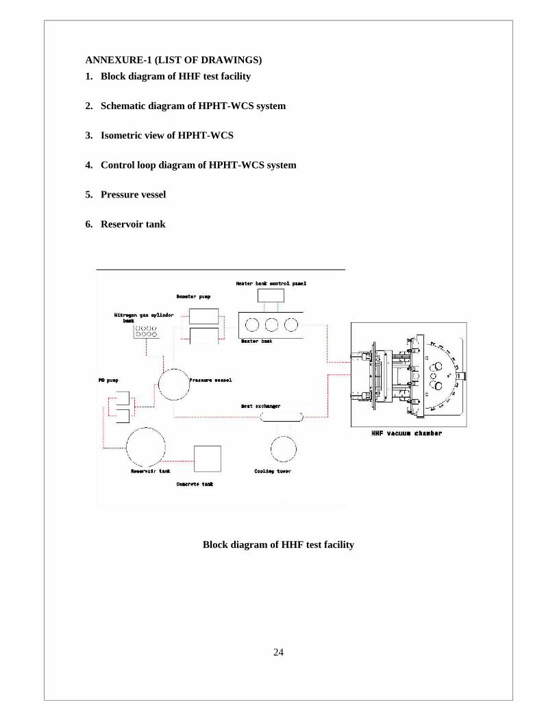
10 mm – 20 mm and maximum length up to 1600 mm. The block diagram of HHF test
facility is shown in Annexure 1.
Institute for Plasma Research requires the fabrication, installation and subsequent
commissioning of the entire water circulation system as a part of its high heat-flux testing
facility that is being developed. For detail design concept and scope of work, refer section 3
& 4.
2. DESCRIPTION
The high pressure high temperature water circulation system has been designed to cool down
the test mock-up which is connected to the test facility. The test mock-up connected to the
water circulation loop has a maximum heat load of 210 kW. In this test loop de-mineralized
water (D.M water) is used as a working medium and system can operate in the pressure range
of 5 bar to 60 bar and the temperature range of 25oC to 160oC. Nitrogen is used as covering
gas to pressurize the D.M water in the pressure vessel. The Nitrogen source (bank of nitrogen
cylinders) connected with pressure vessel and a pneumatic pressure regulator controls flow of
Nitrogen into the pressure vessel.
Minimum pressure in the water circulation system depends upon the operating
temperature of the working medium (DM water). The system pressure of water circulation
loop is usually maintained 4 bar above saturation pressure for the safe running of the test
facility. Testing will start only after stabilizing the pressure and temperature in the water
circulation loop. The data acquisition systems (DAS) with instruments are installed along
with test facility to record and control the test parameters pressure, temperature and flow rate.
The test loop is designed as per relevant safety standards.

4
2.1. Operating parameters at the inlet of test section
Operating Pressure at test section (inlet) 5 bar - 60 bar (a) with variation of ± 1 bar
Operating Temperature Range at testsection (inlet / outlet)
25oC – 160°C with variation of ± 1°C
Required volumetric flow rate at testsection
Up to 300 LPM with ± 1% accuracy
2.2. Details of proposed design
The major components of the test loop are concrete tank, reservoir tank, two positive
displacement pumps with motor, pressure vessel with accessories, bank of Nitrogen
cylinders, two booster pumps with variable frequency drive, orifice type or vortex type flow
meter, heater bank, cooling tower, different types of valves at various locations, safety
devices; pressure, temperature, level and other sensors/indicator/transmitters with controllers.
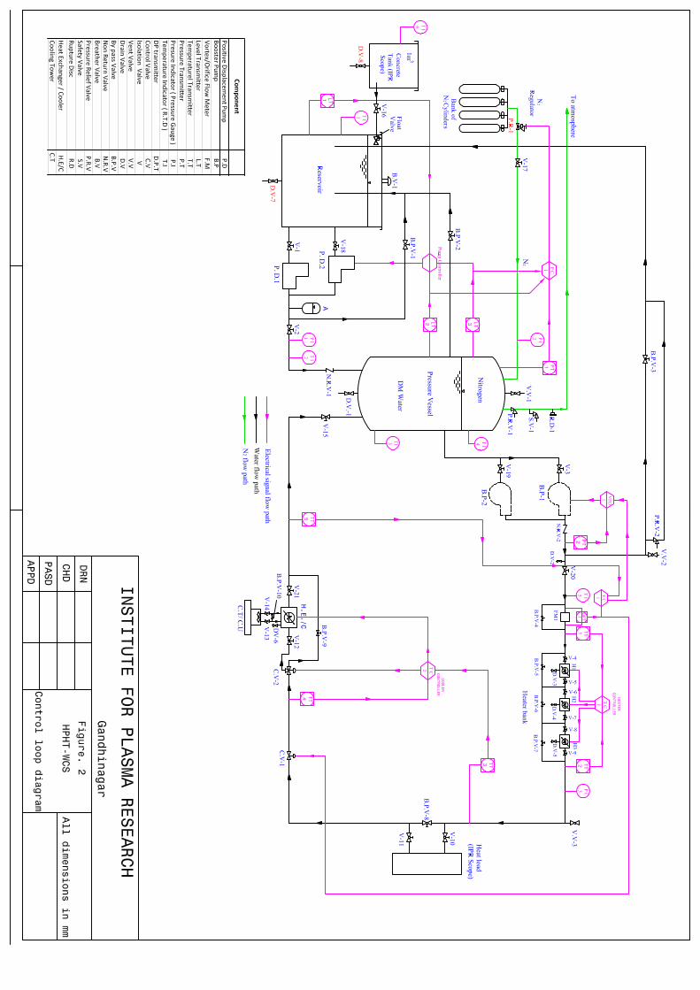
The Piping & Instrumentation diagram (P & I D) & schematic diagram of high pressure high
temperature water circulation system (HPHT-WCS) with inert gas pressurization is shown in
Annexure 1.
3. TECHNICAL SPECIFICATIONS
3.1. Basis of design
Proposed system design / engineering may be treated as indicative. The Vendor may redesign
/ modify / optimize the system or part of the system design if required. All the changes /
modifications are subject to approval by IPR. The Vendor is to give overall system
performance guarantee.
3.2. Site condition
1. Site: Institute for Plasma Research, Gandhinagar, Gujarat.
2. Outdoor design conditions:
Summer : 43.5°C DBT, 28.0°C WBT
Monsoon : 32.2°C DBT, 29.5°C WBT
Winter : 15.5°C DBT, 10.5°C WBT
3. Indoor design conditions: LABs.
Temperature: 24 ± 1°C, RH: 60 %.
4. Extreme ambient conditions:
Temperature: Max. 47°C. Min. 4.5°C.
RH Max. 86 %. Min. 17 %

5
5. Rain fall: Average 823 mm.
6. Wind data: Max. Wind speed: 130 Km/hr.
Wind direction: SW to W.
Design wind pr.: 100 kg / m2
7. Site elevation: 55 m above MSL.
8. Seismic data: 0.04 g As per IS 1893 -1975.
3.3. Design Concept
The high pressure high temperature water circulation system (HPHT-WCS) is designed to
provide and maintain necessary temperature, pressure, flow to cool plasma facing
components / test mock-ups integrated with HHF test facility.
Following aspects are considered for the system design:
Integrated and modular system design.
Automatic / Self-regulating system operation with necessary safety and capacity controls.
Emergency generator power for backup whenever / wherever required like for DAC
system etc.
Provision for projected future upgrading of any system / subsystem like redundancy of
any subsystems like pumps etc.
3.4. System Components
Following components are to be interconnected to satisfy the system requirements. For
components detail specifications refer Annexure 2.
(1) Reservoir tank (R-1)
The reservoir tank (R-1) is filled with de-mineralized water (DM water), the suction of the
positive displacement pump (P.D. Pump) is taken from the reservoir. The capacity of the
reservoir is 2000 litres and it is made of SS 316 material (ref fig in Annexure 1)
(2) Positive displacement pump (P.D 1 and P.D 2)
The purpose of the PD pump is to fill and maintain the level of DM water in the pressure
vessel. The discharge of the P.D pump can be controlled by using the pump controller (by
controlling the speed of the driving motor), which receives the input signals from the level
transmitter (L.T -1), installed on the reservoir tank and also from the level transmitters (L.T-2
and L.T-3), which are connected on the pressure vessel. A bypass line is provided in the
delivery side of the pump (bypass is act as a safety feature), to bypass water to the reservoir
tank by operating the bypass valve (BPV-1). Bypass is provided for the pump start-up

6
requirement and also for process safety. A non return vale (NRV-1) is connected on the
discharge line to prevent reverse flow. An accumulator (A) is fitted near the delivery side of
the P.D Pump, to get uniform flow of discharge during operation. Two PD pumps are
connected in parallel to ensure the availability of the loop.
(3) Pressure vessel (P.V)
Pressure vessel is a closed container (as per ASME boiler pressure vessel code, Section VIII,
DIV 1- 1999) designed to operate safely at 70 bar pressure and temperature up to 200°C. It is
a cylindrical shaped vessel with semi elliptical heads at both ends mounted vertically on leg
supports. The capacity of the pressure vessel is 2.3m3 where one third (1/3) of volume of
pressure vessel is filled with Nitrogen gas and two third (2/3) of volume is filled with DM
water. The required pressure in the loop is achieved with inert gas (Nitrogen) pressurization
where Nitrogen gas is used as covering gas to pressurize the DM water in the pressure vessel
and maintain required pressure. The Nitrogen source (bank of Nitrogen cylinders) is connected
to pressure vessel and a pneumatic pressure regulator controls flow of Nitrogen in to the
pressure vessel. The details of the vessel are provided in the Annexure 1.
(4) Booster pump (B.P-1 & B.P-2)
Booster pump is used to maintain the required flow of DM water in the re-circulation loop
during testing. The booster pump receives water from the pressure vessel and supplies to the
heater bank. Booster pump will create the required pressure to compensate the pressure drop
in the system as water passes through the loop. The speed of the booster pump motor is
controlled by a variable frequency drive (VFD). A by-pass line is also provided in the delivery
side of the booster pump, to bypass water to the reservoir tank by operating the bypass valve
(BPV-3). It will be used to control flow in the main loop and maintaining the required pressure
in the loop (in addition to the control valve and VFD in the loop). It can also be used as a
safety measure, provide operation flexibility and helps during pump test run, pump
maintenance etc. The capacity of booster pump is 70 bar working pressure, 10 bar boosting
pressure, 300 LPM flow rate and operating temperature up to 200°C.
(5) Flow meter (F.M-1)
For measuring the flow rate a flow meter (an orifice plate with differential pressure transmitter
or vortex type flow meter) with a flow range of 10 to 300 LPM and temperature range up to
200°C is connected in the downstream of the booster pump. The output of flow meter is
communicated to the control valve through the flow controller to ensure the required flow rate
in the loop.

7
(6) Heater bank (H)
In the test circuit three separate electrical heaters (H1, H2 & H3) connected in series. These
heaters are used to rise the water temperature to the required value during start up and
maintain the same during running of the loop. Each heater is provided with bypass
arrangement with isolation valve. Of the three heaters, two heaters will be operated in the ON /
OFF control mode whereas the third heater will be provided with a PID controller. This
facilitates to use each heater independently for different load conditions. The capacity of each
heater is 200 KW. Heater controller regulates the power to the heaters based on the
temperature of DM water in the test loop.
(7) Heat exchanger
During testing, the temperature of the DM water will increase maximum by 10°C when it
passes through the test mock-up (corresponding to a maximum heat load of 210 kW). The heat
exchanger along with cooling tower is employed after the test mock –up in the water
circulation loop, to cool down the temperature of water coming from test mock-up to the
required level. It is proposed to use shell and tube type heat exchanger. The details of heat
exchanger are provided in the Annexure 2.
(8) Cooling tower
Cooling tower is operated at full load capacity of 108 TR. It is used as a heat sink for rejecting
heat from test mock –up to atmosphere. It is proposed to install induced draft FRP cooling
towers. Cooling Towers shall be selected for the most stringent Monsoon wet bulb
temperature (29.5 °C) and summer dry bulb temperature (43.5°C) with a approach of about
3.5°C and range of about 3 to 5°C for this application. The mass flow rate of the cooling
medium (DM water) is 18 kg/s.
(9) Piping, valves and accessories
All pipes, valves, fittings and other components used in the test loop are selected in according
to the recognized standard (ASME B31.3) for the designed working pressure of 70 bar and
temperature of 200oC. Pipe system contains sufficient number of valves to operate the system
properly and also for the safe running of the loop. Drain line is connected to the low point of
each pipe line for the complete draining of water for inspection and maintenance; and the
venting connections are provided to vent valve for air venting. Expansion and contraction of
pipe are need to be considered during system operating conditions. Filters are needed to be
incorporated in the design at proper locations in the system to avoid any foreign particles in
the loop. The Details of Piping & valve Specifications are attached in annexure-2.

8
(10) Insulation
Insulation material for pressure vessel, pipe and other accessories shall be Perlite. The thermal
conductivity of perlite at 100°C is 0.07 W/m°C. Thickness of the insulation shall be 50 mm.
Each lot of insulation material delivered at site shall be accompanied with manufacturer test
certificate for thermal conductivity values and density. Adhesive used for setting the insulation
shall be non-flammable, vapor proof adhesive, Shalimar CPR compound, or approved equal,
cold setting compound.
(11) Water chemistry
Required properties of water temperature at 33°C
Turbidity: 50 ppm (silica scale), Max.
Chlorides: 500 ppm, Max.
Total solids: 3000 ppm, Max.
pH: 6.5 to 8.5
Specific Gravity: 1.004, Max.
Hardness: 300, Max.
(12) Instruments and control system
Necessary instruments, sensor- transmitters, Controls- transducers are used for the purpose of
process measurement, indication, control, providing required output signals for data
acquisition- monitoring and control system for the integrated operation of circulation system
with HHF test facility. Refer PID in the Annexure 1.
(13) Central data acquisition and control system
DACS (Data acquisition and Control system) includes all hardware (DDCs, system
controllers, CPU, Monitor, printer, Communicator), software, including electrical control
panel boards with all electrical components, accessories, power wiring, control wiring,
earthing and interlocking, electronic and digital components etc. The central DACS is to be
installed in the plant room control cabin with following hardware and necessary customized
software.
Necessary dial type pressure and temperature gauges are proposed to measure the
water pressure and temperature respectively at inlet and out let of each pumps, heat
exchangers, loads etc. wherever required.
Necessary water flow meters are proposed to measure the water flow mainly at inlet or
out let of the system, wherever required.

9
Necessary sensors – transmitters (pressure, temperature, conductivity, pH & level) can
be installed for necessary data acquisition required for overall monitoring and control
system in the main circulation system.
Necessary capacity controls / diverting / solenoid valves, safety controls / valves /
switches, DDCs etc. are proposed to control the operating parameters.
Necessary pressure vessel accessories to indicate and control pressure, temperature and
level of DM water inside the pressure vessel
4. OPERATING PROCEDURE
The HPHT WCS has been designed to cool down the test mock-up. The test mock-up is
appropriately fastened to the test facility with arrangement for by pass DM water during
startup. Before starting the positive displacement pump make sure that the reservoir tank is
filled with sufficient quantity of DM water. Start the positive displacement pump which takes
water from the reservoir at ambient temperature and supplied to pressure vessel by
pressurizing the water to the required pressure set in the pressure controller. Remove the
entrapped air completely inside the pressure vessel with the help of Vent-Valve (VV-1)
mounted on the pressure vessel. Close the Vent-Valve and pressurize the vessel to the
required value with the help of positive displacement pump.
The pressurization of DM water in the pressure vessel is done by inert gas
pressurization system. Advantages of inert gas pressurization system are
Nitrogen gas used in the inert gas pressurization is environment friendly and
inflammable.
The pressure in the vessel can be increased to any value within the pressure limits of
Nitrogen storage tank.
The overall efficiency of the system will be employed.
The P. D Pump needn’t be operated continuously to maintain required pressure. This
will reduce the operating and maintenance cost.
In the inert gas pressurization method, the pressure vessel is initially filled with
required quantity of DM water (approximately 65% of pressure vessel volume) by operating
positive displacement pump. Sufficient quantity of nitrogen at high pressure is stored in the
bank of nitrogen cylinders and it supplied to pressure vessel through a regulator. A high
pressure pneumatic regulator is used to regulate the nitrogen pressure supplied to vessel.
Nitrogen gas is introduced in to pressure vessel until it reaches the required pressure. The
required pressure of DM water in the vessel set on the pressure controller and it controls the

10
operation of the high pressure regulator. The water level in the pressure vessel is maintained
between the desired levels by operating the positive displacement pump. Two level sensors
(L.T-1 and L.T-2) are provided on the pressure vessel to indicate the water level and
communicated to the pump controller to offer the high level pump cut off and low level pump
start up. Thus the required pressure is maintained in the pressure vessel.
A booster pump is used to circulate the high pressure water in the pressure vessel through
the entire closed loop by overcoming the pressure drops in the water circuit. After attaining
required pressure in the pressure vessel, stop the positive displacement pump and switch ON
the booster pump and set the flow rate in the loop to the required value by variable frequency
drive (VFD) and also by main control valve (CV-1). The flow rate has to be measured by
vortex type flow meter / orifice type flow meter located in the discharge line of the booster
pump. The differential pressure recorded by the differential pressure transmitter (DPT-1) is
proportional to the flow rate of the DM water passing through the flow meter and it is
communicated to booster pump by a flow controller. The heater has to Switch ON (number of
heaters has to switch ON based on the heat load of external mock-up) to increase the
temperature of the DM water to the required level (150oC). When the external heat load is
210 kW (maximum value) and flow rate is 300 LPM, the temperature of DM water raised to
160oC. The temperature of the DM water passes the test mock up is reduced by cooler and
then return back to pressure vessel. The time taken to reach steady state temperature for the
entire loop depends on the different factors; namely, flow rate of DM water, external heat
load, total volume of water in the test loop and heat energy supplied by the heater. Stability of
the operating parameters (pressure, temperature, flow rate) for a time scale of 10 sec during
heat load on the test mock –up is to be ensured by the entire system.
5. DATA ACQUISITION AND CONTROL SYSTEM
The Control and monitoring of HPHT-WCS with inert gas pressurization method comprises
with number of individual controllers, they are,
1. Pump controller
2. Pressure controller
3. Flow controller
4. Temperature controllers

11
(1) Pump controller for positive displacement pump
The pump controller acts as a primary controller to maintain the required water level and
pressure in the vessel. The DM water pressure inside the vessel depends on the level of water
in the vessel. The water level inside the pressure vessel can be controlled within the desired
limit by start and stop of the positive displacement pump (P.D Pump) with the help of the
pump controller. Change in water level inside the pressure vessel is monitored by level
transmitters (L.T-2 and L.T-3) and the corresponding signals are fed to the pump controller.
The water level reaches a predetermined minimum level (sensed by level transmitter L.T-2),
the pump controller generates a control signal that turns the P.D pump ON and once the water
level has reached the predetermined maximum level (sensed by level transmitter L.T-3), and
the pump controller generates another control signal that turns the P.D pump OFF. Starting of
the pump also depends on the water level in the reservoir. The height of the DM water in the
reservoir is measured by level transmitter (L.T-1); to ensure minimum water in the tank while
the P.D pump is in operation. All other protections like overload, two phase will also be
provided for the pump.
(2) Pressure controller to regulate the pressure inside pressure vessel
The pressure controller acts as a secondary controller to maintain the required pressure in the
vessel. The Nitrogen gas is used to pressurize the DM water in the pressure vessel and a
pneumatic pressure regulator (PR-1) controls flow of Nitrogen in to the vessel. Whenever, the
pressure inside the vessel decrease more quantity of Nitrogen has to be supplied in to pressure
vessel, by operating pneumatic pressure regulator. If pressure increased the excess pressure
released through pressure relief valve. For this purpose the pressure transmitter (P.T-1)
installed in the top of the pressure vessel and it generate electrical signals corresponding to
pressure inside the vessel and fed to pressure controller (P.C-1).
The control logic for water level and water pressure is provided as below.
As the water level in vessel decreased below the minimum level, the PD pump 1 will be
started to fill water. If PD pump 1 is not started for a specified time and with water level
below minimum then PD pump 2 will start. If both pumps are not started in the specified time
with water level remaining below the minimum level, a trip signal will be generated to trip
the WCS with suitable warning (alarm). The pump (either PD-1 or PD-2) will continue to
operate till the maximum water level is reached. Till that time, the pressure controller (PC-1)
will be inactive and the excess Nitrogen will be released through the pressure regulator. Once
the pump is stopped, the pressure controller (PC-1) will be made to operate and the gas

12
pressure inside the vessel will be made to the required value. Pressure controller (PC-1) will
operate till the water level reaches the minimum level. Thus the pump controller will be active
during the period between minimum water level to maximum water level. Pressure controller
will be active between maximum water level to minimum water level. Time required for
filling water from minimum level (1440 l) to maximum level (1560 l) is ~ 2.4 minutes.
(3) Flow controller to control flow in the water circulation loop
The flow in the water circulation loop is controlled by two ways.
1. By controlling the control valve.
2. By controlling the booster pump using a variable frequency drive (VFD)
By controlling the control vale
A flow meter with analogue output is connected in the water circulation loop downstream of
the booster pump to monitor the flow in the loop. A control valve (C.V-1) with pneumatic
actuator, valve positioner and position transmitter is installed at the outlet of the test mock up
to control the flow. Based on the flow rate requirement of the loop, actual flow rate and valve
position, the valve opening and booster pump speed will be computed. The valve position
determines the amount of flow passing through the control valve. The valve positioner
receives signal from the flow controller and keeps the valve opening according to flow
requirements of the loop.
A temperature transmitter (TT-5) is connected in the downstream side of the cooler /
heat exchanger (C / H.E-1). The function of temperature transmitter is to monitor the
temperature of the DM water leaving the cooler / heat exchanger , it develop electrical signals
corresponding to the line temperature of DM water and communicated to control valve
through flow controller. Whenever the temperature of the DM water increase beyond the limit,
flow controller increases the flow rate and pressure in the loop by controlling the control valve
and keeps the temperature of the DM water leaving the cooler / heat exchanger to specified
level for safety.
By controlling the booster pump using variable frequency drive (VFD)
The variable frequency drive (VFD) is used to control the rotational speed of the booster pump
motor by controlling the frequency of the electrical power supplied to the motor. The VFD
receives the input signals from the pressure transmitter (PT-2) which is fitted in the delivery
line of the booster pump and the flow rate signals from the flow meter are also transferred to
VFD through flow controller. Based on load requirement the booster pump can operate at

13
different speed and maintain the necessary flow rate and the pressure in the water circulation
loop.
Flow and the pressure in the loop are controlled, by combined operation of above mentioned
two controls.
(4) Temperature controller
Two temperature controllers used in the water circulation loop are.
1. Heater controller
2. Cooler controller
Heater controllerThe test loop consists of three separate electrical heater banks connected in series. One can be
controlled by PID heater controller and other two by ON/OFF controller. The rise in
temperature of the DM water flows through the heater bank can be monitored using the
temperature transmitters (TT-1 & TT-2) and the transmitter output signals are communicated
to heater controller. Power to the heater bank works in relation with the signals from the
heater controller. Whenever temperature of the DM water at the outlet of heater bank falls
below the lower set point, an appropriate power rise happen in the heater till the temperature
reaches the set value and vice versa.
Cooler controller
Cooler or heat exchanger employed in the water circulation loop to cool down the
temperature of water coming from test mock to the required level. To measure the
temperature rise due to the external heat load, two temperature transmitters (TT-3 & TT-4)
are connected on the inlet and exit line of the test mock-up. The output signals corresponding
to increase in temperature is transferred to PID type cooler controller; it control and regulate
the flow of DM water through the three way control valve (CV-2), depending upon the
temperature rise due to external heat load. The Bypass valve (BPV-10) is provided to control
the cooling water flow.
6. VENDORS SCOPE OF WORK
The Vendors scope of work for the system includes validation of the design, Manufacturing /
Fabrication, Shop testing, Supply, Installation (including, lifting, shifting, assembling etc.),
Site testing, and Commissioning of the following system components (confirming to tender
specifications, relevant BIS & ASME codes mentioned in Annexure 5 and in accordance with
the requirements of schedule of quantities and approved drawings).

14
6.1. Validation of proposed Engineering design
1. Vendor shall validate the proposed Engineering design and optimize the process
parameters of the system (if required) based on the given requirement and shall obtain
IPR’s approval before proceeding further.
2. Vendor shall prepare engineering drawings based on approved design reports and
from supplied general assembly drawings. Vendor shall get it approved by IPR.
6.2. Operation and control system specifications
Mandate:
The operation and control system will be responsible for the ensuring the fail safe operation
of the HPHT system as a whole and all its subsystems. This system is expected to operate in
semi-autonomous mode. It must be provided with the manual operation interface and should
have an independent operational control system. It must be able to integrate to PXI and PLC
based High Heat Flux Test Facility (HHFTF - OCP) operation and control system. The
project must be able to provide SCADA level functionalities.
Note:
I&C for the HHFTF-OCP is indented as combination of PLC and PXI and the Electron beam
gun source is controlled by Siemens controllers. Hence, I&C controllers for the project must
be compatible in terms of software integration and hardware integration point of view. The
standard technology interface supports e.g. OPC and OPC-UA is preferred.
Functionality
The Operation and control system must be able to perform following tasks
Operational functionality
o I&C must be able to measure the process parameters at various points in the
loop and able to compensate the difference w.r.t. to set points by appropriately
modify various subsystems parameters.
o The main operational parameters must be settable by user interactively and
system must be able to maintain it.
o The system must be able to show the possible diagnostics scenarios in case of
pressure, temperature and flow loop fails.
o The operational control for regular maintenance and calibration of I&C
sensors and actuators must be provided.

15
Interlocks
o The system must provide the interlocks at subsystem and system level by
implementing it at software and I&C level.
o Failure of a pump and subsystems must be detectable automatically and
appropriately alternate signal path must be chosen.
Safety
o The safety actuators and sensors must be redundant and failure scenarios must
be demonstrated on site.
SIGNALS
The signal list will be finalized after finalization of engineering design and location of
sensors/actuators. It is expected that the signal acquisition will be configurable from 200 ms –
1000 ms. The tentative list is as below as per P&ID
1. Signal for process parameter measurement (Pressure, temperature, flow at different
locations in the loop)
2. Signals for control (pressure, temperature, flow)
3. Signal for monitor (level, flow, temperature, status monitoring)
All the signal must be controlled and monitored from Operator Software interface and alarms
levels must be represented appropriately.
Deliverables
Documents
o High level architecture document for I&C and software
o I&C Engineering design documents
o Software Engineering design documents
o Signal integration schema
o I&C and Software test reports
o User manuals
Training
o Training on the different software and hardware used into the system must be
provided to the IPR personnel’s.
Hardware
o I&C Controllers
o Accessories like Cubical, Power supplies Cables and connectors
Software
16
o Control loop code
o Controller and I/O module configuration code
o Code for various operational scenarios with load and without load
o Operator display and archival of the signals (The operational database system
for HHFTF-OCP is postgresSQL hence integrity is preferred.)
o Any other relevant code not mentioned above
o All the licenses of the software used for implementation
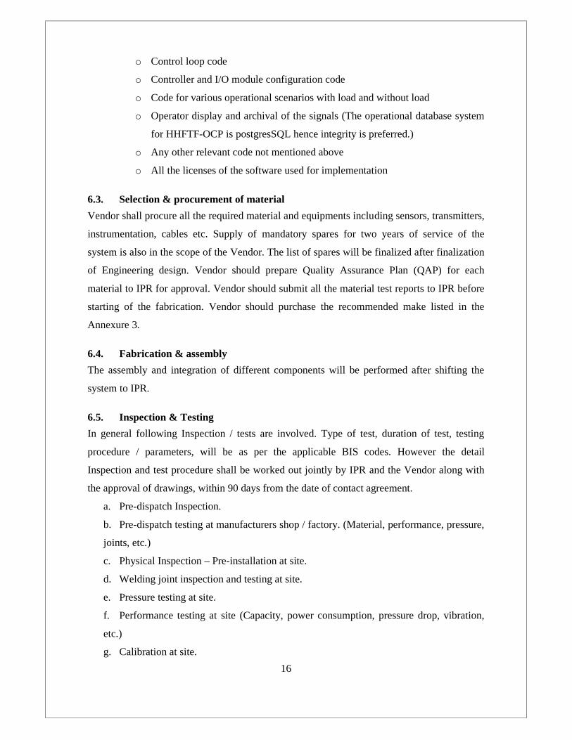
6.3. Selection & procurement of material
Vendor shall procure all the required material and equipments including sensors, transmitters,
instrumentation, cables etc. Supply of mandatory spares for two years of service of the
system is also in the scope of the Vendor. The list of spares will be finalized after finalization
of Engineering design. Vendor should prepare Quality Assurance Plan (QAP) for each
material to IPR for approval. Vendor should submit all the material test reports to IPR before
starting of the fabrication. Vendor should purchase the recommended make listed in the
Annexure 3.
6.4. Fabrication & assembly
The assembly and integration of different components will be performed after shifting the
system to IPR.
6.5. Inspection & Testing
In general following Inspection / tests are involved. Type of test, duration of test, testing
procedure / parameters, will be as per the applicable BIS codes. However the detail
Inspection and test procedure shall be worked out jointly by IPR and the Vendor along with
the approval of drawings, within 90 days from the date of contact agreement.
a. Pre-dispatch Inspection.
b. Pre-dispatch testing at manufacturers shop / factory. (Material, performance, pressure,
joints, etc.)
c. Physical Inspection – Pre-installation at site.
d. Welding joint inspection and testing at site.
e. Pressure testing at site.
f. Performance testing at site (Capacity, power consumption, pressure drop, vibration,
etc.)
g. Calibration at site.

17
6.5.1. Testing the equipments at Site
The following aspects shall be considered for performance testing.
Prevailing conditions shall be as close as to design conditions.
Type, quantity, location, frequency, duration of test parameters shall be decided and
recorded accordingly during the test.
Rated capacity, power consumption, and other operating parameters shall be checked.
Functional test for all Instruments, controls (safety and capacity) and DACS shall be
carried out to check for the expected operation / action / accuracy / response time /
repeatability parameters.
6.5.2. Pre -dispatch Inspection & Testing at Vendors site
Pre-dispatch inspection and testing (including stage wise inspection) at manufacturer’s /
fabricator’s place must be carried (in presence of IPR representative or as per approved QAP
submitted by the Vendor) for the system components. In case of larger quantity of similar
size and configuration the sampling can be done as per the applicable test code. Pre-dispatch
testing includes performance testing for the rotating / moving equipments, parts Instruments
& controls according to the approved technical specifications and drawings. The Vendor
must absorb all the charges for the pre-dispatch inspection and testing. System parts duly
inspected and tested will be stamped / marked and cleared for dispatch by IPR representative.
All the system parts shall bear the marking when received at site for the verification of IPR
representative. A copy of all the test certificates, performance data / curves, operation and
maintenance manual etc. must be submitted to IPR representative.
Site Inspection and Testing
1. All the tests shall be carried out in the presence of the representative of IPR. All
instruments, services, required for the tests shall be provided by the Vendor.
2. All the system components (Including the parts cleared after pre-dispatch inspection
and testing) will be physically inspected and tested before and after installation
according to approved specifications and drawings.
3. Capacity ratings and power consumption with operating points clearly indicated shall
be submitted and verified at the time of testing and commissioning of the installation.
Manufacturer’s tests certificates shall be furnished for all equipments / materials.
4. The Vendor shall demonstrate the capacity and the power consumed by the
equipments.

18
5. The Vendor shall also demonstrate the proper operation of all controls, Instruments
and other equipments.
6. Integrity test for rubber lining for equipment and piping by spark testing shall be
carried out.
7. Alignment of drives, checking of abnormal vibration, noise, running tests for pumps,
etc. shall be carried out.
8. Water piping, fittings shall be tested to hydraulic test pressure of at-least one and half
(1.5) times the maximum operating pressure as per the QAP, at least 2 hrs. Any
leaks, defects shall be rectified and re-tested in same manner. After completion of the
installation, all water system shall be adjusted and balanced to deliver the water as
specified. (All piping shall be measured in units of length along the centerline
including of all joints, bends, fittings, flanges and other accessories).
Welding: Inspection &Acceptance Standards:
Following Inspection and testing shall be carried out.
Root and final run for Butt-welds, Nozzle welds, Structural attachment weld, Hanger,
Support welds, socket welds etc. shall be checked with –
-100 % Visual examination + 10 % DP (Dye Penetration) examination + sample
Radiography (SS piping- 100 NB and above)
-100 % Visual examination +100 % DP examination + sample Radiography (Pr. Vessels
and tanks & for socket welds)
-100 % Visual examination + 10 % DP examination for Structural welds.
Visual Checkup Includes : Base metal identification, Base metal defects rectification,
Edge preparation, Joint - Fit-up checking for both longitudinal and circumferential
welding, Check of pipe –dia., Cleanliness, Tacking, Root pass & subsequent pass
appearance, Cleaning between the passes, Completed weld appearance, Condition of the
base metal in the area adjoining the welds, Excessive distortion if any due to welding.
DP examination: Procedure shall be as per Pr. Vessel code. However it includes: Check
for any crack or linear indication, porosity, or slag inclusion.
Tolerances for Fabrication of pipes and fittings:
Pipes:
Dia: Tolerance: ± 0.5 % of OD.( Check by measurement of circumference), Length : < 5 mm
for 3 m length., Roundness : 1 % of Pipe Dia.

19
Fittings:
Angular Dimension: ± 1/8” degree.
OD at Bevel: Nominal + 6.25 mm - 4.5 mm.
ID at Bevel: Nominal ± 2.25 mm
Reinforcement Pads for Structural attachment: with gap < 1.5 mm.
Radiography: For pipe 100 mm and above and pressure vessels, selection of the location
and dia. of the pipe and sample size shall be at the discretion of quality supervisor from
Purchaser. If a joint or weld length is acceptable, the remaining length by same welder or
group length shall be acceptable. In case of rejection two more length from the same lot /
group shall be examined at the discretion of quality supervisor from Purchaser. If weld
joints found defective after second radiography examination, all the remaining group
joints shall be rejected. However the contractor shall have option of 100 % radiography.
Welds with the crack, slag inclusions, cavity and incomplete fusion shall be rejected.
Repair of Welds: Welds shall be repaired by additional welding in case of dimensional
problem, but new weld joint to be done for deficient quality. Cracks can be removed by
grinding, chipping, arc or flame gouging with DP test.
Valves:
Physical, material, machining check shall be carried out stage-wise as required.
Hydro-pneumatic leakage test for Body, seat shall be carried out for the time duration as per
BIS code, including shop torque test for gear operated and motorised valves. All technical
performance parameters shall be checked within the allowable tolerance.
6.5.3. Test Certificates
Vendor shall furnish following Test certificates.
Material testing of various components of the equipments/ system parts.
Fabrication inspection / test certificates– Radiography and others
Welder’s qualification certificate.
Performance test certificates carried out by manufacturer before Pre- dispatch inspection
& testing.
Performance test certificates carried out by manufacturer.
Performance guarantee certificate./ calibration certificate/ balancing certificate.
Performance curves of all equipment, along with operation and maintenance manual.

20
7. COMPLETION OF ERECTION & COMMISSIONING
All the equipments shall be installed for the lowest operating noise level. All equipments
shall be mounted on concrete foundation, through cushy foot mountings or as per
manufacturer’s recommendations. All equipments shall be installed so as to have ease of
operation and maintenance.
Electrical work:
Electrical installation shall be carried out in accordance with the specifications, local rules,
Indian Electricity Act 1910 as amended up to date and rules issued thereunder, regulations of
the Fire Insurance Company and relevant BIS code of practice. Sizing of panel board, general
arrangement and all wiring system shall be approved by IPR, before fabrication, wiring etc.
Painting:
All equipments shall be supplied with approved finish, shop coat of paint that have become
marred during transportation or erection, shall be cleaned off with mineral, spirits, wire
brushed and spot primed over the affected areas, then coated with enamel paint to match the
adjoining areas or as directed by IPR.
8. ACCEPTANCE CRITERIA
1. System components or system as a whole shall be tested for performance as per the
various operating conditions like (1) 60 bar, 150°C, 300 LPM for 1 hour (2) 10 bar,
100°C, 100 LPM for 1 hour (3) 5 bar, 50°C, 50 LPM for 1 hour as suggested by IPR
to check the stability of the entire system at different conditions. System can be
accepted and taken-over by IPR for regular operation only after satisfactory
performance testing in all respect. All the system components shall meet the
guaranteed performance & safety requirements to the satisfaction of IPR.
2. Necessary replacement / modification / rectification shall be carried out with the
approval of IPR. The installation shall be tested again after removal of defects and
shall be commissioned only after approval by the IPR.
3. No visible leaks and permanent deformations in the total system after the tests.
9. DELIVERABLES
The following are the documents to be submitted to IPR
1. System description, design calculations and selection criteria or details.
2. Detailed Engineering drawings in soft copy as well as hard copy.
3. Detailed PFD and P&ID of the optimized flow loop system.

21
4. Equipment technical data, Operation and maintenance manuals.
5. Photographs taken during various stages of fabrication, X-radiography reports.
6. Details of the procedure and material test reports carried out during various stages of
development along with rating charts, performance curves etc.
7. Inspection and performance test reports (Including pre-dispatch, site test reports).
8. Details of additional utilities prior to the installation such as space taken by the entire
system, power requirements for the individual components and the entire system,
amount of nitrogen gas required to run the system after commissioning, safety
requirements.
9. Detailed operation manual of the entire system which contains operational limits of
the system including the control systems, individual components, various operating
procedures, safety, troubleshooting etc.
10. Complete installation and testing of the entire system, including the individual
components under all conditions as per design criteria.
11. List of recommended spares and cost, Rate for maintenance contract valid for five
years (for Chillers and DACS system) from the date of handing over.
10. QUALITY CONTROL AND ASSURANCE TEST
The Vendor shall submit Quality Assurance plan (QAP) to IPR for the approval with detailed
time schedule for entire scope of work as per the QAP given in Annexure 6. The quality
assurance plan shall include all the stages starting from specification and covering material
procurement, identification of raw material, fabrication of equipments and up to final
acceptance. Design & engineering, fabrication, testing, inspection, erection etc shall be
covered in Quality Assurance plan (QAP) which will be submitted to IPR for final approval.
IPR reserves the right to appoint a third party for inspection/testing of work done. Vendor
shall have no objection for third party inspection and testing. The cost for third party
inspection will be borne by IPR. Sub-Vendors (if any) are required to be appraised and
approved by IPR before placement of contract job to the sub-Vendor.
11. GUARANTEE
Vendor shall give guarantee / warranty for the performance of the entire system for twelve
months (12 Months) or more from the date of final acceptance. During this period if any fault
occurs, Vendor shall rectify at IPR site without extra cost. If the components have to be sent

22
to the Vendor site, the total expense for to and fro transportation including insurance shall be
beard by Vendor.
12. SAFETY
Vendor shall submit the details of Safety norms/precautions followed for site activities in
routine work. Since the design pressure is fairly high, safety valves at appropriate location of
adequate capacity shall be worked out in accordance with ASME codes, during the
finalization of the P&ID drawings like safety relief valves, over temperature sensors, etc.
Vendor is advised to make a visit at IPR site to understand the IPR site constraints before
quoting if necessary. Safety approval of different components like pressure vessel from
CCOE Nagpur and total system from concerned safety department is under the scope of
Vendor.
13. GENERAL TERMS AND CONDITIONS
1. In case the Vendor is involving any outside party for any purpose, he shall give the details
of the concerned party and get the approval of IPR before doing so.
2. Understanding and knowledge of all the technical areas covered in the scope of work.
3. Experience /arrangement (provide the details of agencies planned for outsourced /
subcontract activities) with, pressure test.
4. The qualification of the people to be employed for the job with organization structure and
how he will execute the work if awarded
14. COMPLETION PERIOD
The total completion period estimated is about 9 months from the date of LOI, however the
Vendor shall clearly indicate the deviation if any. This period includes the approval of
drawings also. The work in totality must be completed within the completion time period as
per approved Bar chart / Project schedule. The entire project is to be completed at the earliest;
hence the Vendor’s labour may have to work on 24 hours basis / round the clock if required,
with necessary prior permission. Necessary penalty shall be applied as per the Penalty / L.D
clauses in case of delay on part of Vendor.
15. BAR CHART/ PROJECT SCHEDULE & PERIODICAL PREVIEW
The Vendor shall provide preliminary Bar chart along with the offer to justify the specified
completion period. The successful Vendor has to prepare Bar Chart / project schedule in
detail, covering activities for all the parts / components and entire system. The Bar chart,

23
PERT chart must be approved by IPR. Periodical / regular progress review of the entire
project work will be carried out at site at least once in a month and same shall be submitted as
site progress report by the Vendor to IPR. However detail of review meeting schedule can be
worked out mutually. Vendor must take corrective measures; follow up action agreed /
suggested during such review meetings.
16. DRAWINGS
Drawings enclosed with Tenders given in Annexure 1 are schematic only and indicate the
extent of work covered in the contract. The drawings broadly suggest the concept and routes
to be followed. The actual site details shall be examined for exact location of equipments and
other system parts.
The Vendor shall follow the tender drawings in preparation of shop floor drawings after
detail engineering. All the shop floor drawings (including electrical) must be approved before
manufacture / supply / installation. Any modifications / changes required to coordinate
installation work as per site conditions, shall be made in consultation with and approval of
IPR. Within 8 weeks after the award of the contract, the Vendor shall furnish three sets of
detailed shop floor drawings, including overall system flow diagram (P & I diagram), Plant
room layout, Piping & Equipment layout, foundation/ support details, Electrical - panel
boards G.A. diagram, power and control wiring diagram etc. with necessary sectional views
as required for the approval of IPR. 3 D & / or Isometric views shall be prepared as per the
instruction of the IPR.
All drawings shall be submitted for approval in hard as well as soft copy in the size as desired
by the Engineer In-charge.
24
ANNEXURE-1 (LIST OF DRAWINGS)
1. Block diagram of HHF test facility
2. Schematic diagram of HPHT-WCS system
3. Isometric view of HPHT-WCS
4. Control loop diagram of HPHT-WCS system
5. Pressure vessel
6. Reservoir tank
Block diagram of HHF test facility


30
ANNEXURE-2 (TECHNICAL SPECIFICATIONS)
(1) Reservoir tank
Capacity 2000 litersDiameter 1.5 mHeight 1.2 mThickness 5 mmMaterial SS 316
(2) Positive displacement pump
Flow rate 50 LPMMaximum pressure 70 barTemperature 25oC to 80oCFluid medium DM waterPower 16 kWSuction size 50 mmDelivery size 50 mmPump input power 18 hpMotor power for pump 16 kWPower supply 415±10 % volts, 3 phase, 50 cycles, ACMaterial for construction SS 316 for wetted parts and carbon steel for
other parts Installation: The pump shall be installed on a concrete foundation
Performance: All the pumps must perform according to selected duty point and
respective performance curve. Pre-dispatch performance test and site performance test
shall confirm the design / required performance.
(3) Pressure vessel
Design pressure (P) 70 barDesign temperature (T) 200oCMaterial SS 316Dimensions Attached in annexure1Shell height 2.44 mShell diameter 1.1 mThickness of cylindrical shell 40 mmThickness of top and bottom head 36 mmSupport Leg support (4 nos)Support leg I section thickness 12 mmTotal volume 2.3 m3
Water volume in the pressure vessel 1.5 m3
Nitrogen gas volume in the pressure vessel 0.8 m3
31
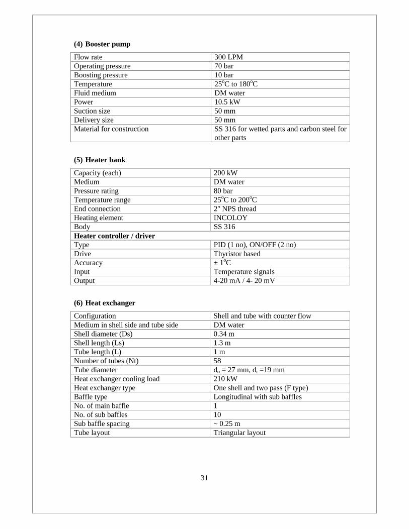
(4) Booster pump
Flow rate 300 LPMOperating pressure 70 barBoosting pressure 10 barTemperature 25oC to 180oCFluid medium DM waterPower 10.5 kWSuction size 50 mmDelivery size 50 mmMaterial for construction SS 316 for wetted parts and carbon steel for
other parts
(5) Heater bank
Capacity (each) 200 kWMedium DM waterPressure rating 80 barTemperature range 25oC to 200oCEnd connection 2ʺ NPS threadHeating element INCOLOYBody SS 316Heater controller / driverType PID (1 no), ON/OFF (2 no)Drive Thyristor basedAccuracy ± 1oCInput Temperature signalsOutput 4-20 mA / 4- 20 mV
(6) Heat exchanger
Configuration Shell and tube with counter flowMedium in shell side and tube side DM waterShell diameter (Ds) 0.34 mShell length (Ls) 1.3 mTube length (L) 1 mNumber of tubes (Nt) 58Tube diameter do = 27 mm, di =19 mmHeat exchanger cooling load 210 kWHeat exchanger type One shell and two pass (F type)Baffle type Longitudinal with sub bafflesNo. of main baffle 1No. of sub baffles 10Sub baffle spacing ~ 0.25 mTube layout Triangular layout

32
(7) Cooling tower
Capacity 108 TRType Induced draftMaterial Fiber reinforced plasticPower supply 415±10 % volts, 3 phase, 50 cycles, AC
Piping & Valve specifications
Pipe (P) Schedule 80MOC : SS 316 ASTM A-312 / A-213Velocity of flow in loop: 2.55 m/sDiameter : 60 mm (NB) & ~ 10 m lengthDiameter : 50 mm (NB) & ~ 25 m lengthDiameter : 40 mm (NB) & ~ 2 m length
Pressure Relief valve (PRV-1 & PRV-2) Set Pressure: 60barTemperature range: up to 200 °CTemperature range: up to 200 °CSize : 2.5"End connection: Threaded (NPT)MOC: SS 316 for wetted parts & Carbonsteel for other parts
Safety valve (SV-1) Set pressure : 65 barTemperature range: up to 200 °CSize : 2.5" x 2.5"End connection : Threaded (NPT)MOC: SS 316 for wetted parts & Carbonsteel for other parts
Rupture Disc (R.D-1) Set Pressure: 70 barTemperature range: up to 200 °CSize : 2.5"End connection : Threaded (NPT)Membrane : SS 316
Control Valve (C.V-1) Size : 50 mm (NB)Cv = 50Operating pressure : 80 barOperating Temperature: 200 °CEnd connector: FlangedRating : ANSI 600 RFActuation : Pneumatic with valveOutput: 4-20 mAPositioner and position transmitter MOC :SS 304 (wetted parts) & Carbon Steel(Body)
Isolation valve Type : Full boreOperating pressure : 80 barOperating Temperature: 200 °CRating : 600Size
33
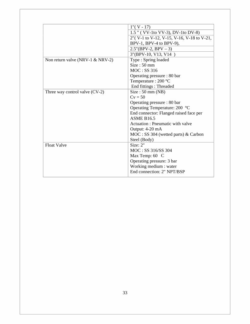
1"( V - 17)1.5 " ( VV-1to VV-3), DV-1to DV-8)2"( V-1 to V-12, V-15, V-16, V-18 to V-21,BPV-1, BPV-4 to BPV-9),2.5"(BPV-2, BPV – 3)3"(BPV-10, V13, V14 )
Non return valve (NRV-1 & NRV-2) Type : Spring loadedSize : 50 mmMOC : SS 316Operating pressure : 80 barTemperature : 200 °CEnd fittings : Threaded
Three way control valve (CV-2) Size : 50 mm (NB)Cv = 50Operating pressure : 80 barOperating Temperature: 200 °CEnd connector: Flanged raised face perASME B16.5Actuation : Pneumatic with valveOutput: 4-20 mAMOC : SS 304 (wetted parts) & CarbonSteel (Body)
Float Valve Size: 2"MOC : SS 316/SS 304Max Temp: 60⁰COperating pressure: 3 barWorking medium : waterEnd connection: 2" NPT/BSP
34
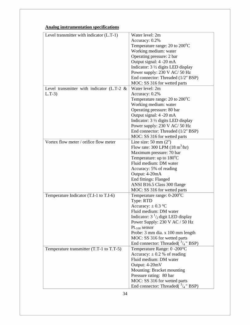
Analog instrumentation specifications
Level transmitter with indicator (L.T-1) Water level: 2mAccuracy: 0.2%Temperature range: 20 to 200oCWorking medium: waterOperating pressure: 2 barOutput signal: 4 -20 mAIndicator: 3 ½ digits LED displayPower supply: 230 V AC/ 50 HzEnd connector: Threaded (1/2ʺ BSP)MOC: SS 316 for wetted parts
Level transmitter with indicator (L.T-2 &L.T-3)
Water level: 2mAccuracy: 0.2%Temperature range: 20 to 200oCWorking medium: waterOperating pressure: 80 barOutput signal: 4 -20 mAIndicator: 3 ½ digits LED displayPower supply: 230 V AC/ 50 HzEnd connector: Threaded (1/2ʺ BSP)MOC: SS 316 for wetted parts
Vortex flow meter / orifice flow meter Line size: 50 mm (2ʺ)Flow rate: 300 LPM (18 m3/hr)Maximum pressure: 70 barTemperature: up to 180oCFluid medium: DM waterAccuracy: 5% of readingOutput: 4-20mAEnd fittings: FlangedANSI B16.5 Class 300 flangeMOC: SS 316 for wetted parts
Temperature Indicator (T.I-1 to T.I-6) Temperature range: 0-200oCType: RTDAccuracy: ± 0.3 °CFluid medium: DM waterIndicator: 3 1/2 digit LED displayPower Supply: 230 V AC / 50 HzPt-100 sensorProbe: 3 mm dia. x 100 mm lengthMOC: SS 316 for wetted partsEnd connector: Threaded( 3/4 " BSP)
Temperature transmitter (T.T-1 to T.T-5) Temperature Range: 0 -200°CAccuracy: ± 0.2 % of readingFluid medium: DM waterOutput: 4-20mVMounting: Bracket mountingPressure rating: 80 barMOC: SS 316 for wetted partsEnd connector: Threaded( 3/4 " BSP)
35
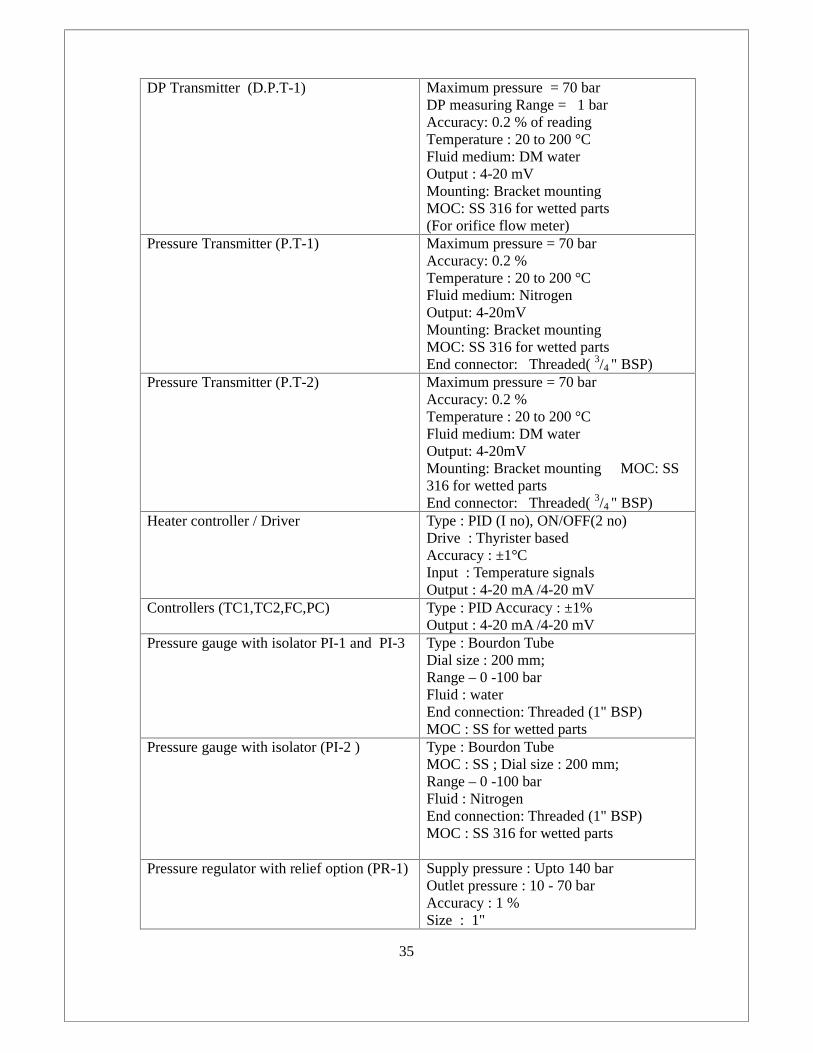
DP Transmitter (D.P.T-1) Maximum pressure = 70 barDP measuring Range = 1 barAccuracy: 0.2 % of readingTemperature : 20 to 200 °CFluid medium: DM waterOutput : 4-20 mVMounting: Bracket mountingMOC: SS 316 for wetted parts(For orifice flow meter)
Pressure Transmitter (P.T-1) Maximum pressure = 70 barAccuracy: 0.2 %Temperature : 20 to 200 °CFluid medium: NitrogenOutput: 4-20mVMounting: Bracket mountingMOC: SS 316 for wetted partsEnd connector: Threaded( 3/4 " BSP)
Pressure Transmitter (P.T-2) Maximum pressure = 70 barAccuracy: 0.2 %Temperature : 20 to 200 °CFluid medium: DM waterOutput: 4-20mVMounting: Bracket mounting MOC: SS316 for wetted partsEnd connector: Threaded( 3/4 " BSP)
Heater controller / Driver Type : PID (I no), ON/OFF(2 no)Drive : Thyrister basedAccuracy : ±1°CInput : Temperature signalsOutput : 4-20 mA /4-20 mV
Controllers (TC1,TC2,FC,PC) Type : PID Accuracy : ±1%Output : 4-20 mA /4-20 mV
Pressure gauge with isolator PI-1 and PI-3 Type : Bourdon TubeDial size : 200 mm;Range – 0 -100 barFluid : waterEnd connection: Threaded (1" BSP)MOC : SS for wetted parts
Pressure gauge with isolator (PI-2 ) Type : Bourdon TubeMOC : SS ; Dial size : 200 mm;Range – 0 -100 barFluid : NitrogenEnd connection: Threaded (1" BSP)MOC : SS 316 for wetted parts
Pressure regulator with relief option (PR-1) Supply pressure : Upto 140 barOutlet pressure : 10 - 70 barAccuracy : 1 %Size : 1"

36
Flow rate : 200 lpmMedium : Nitrogen/ AirEnd connection: Threaded (1" BSP)MOC : SS 316
Calibration and Testing: All automatic controls and instruments shall be factory calibrated
and provided with necessary instructions for site calibration and testing. Various items of the
same type shall be completely interchangeable and their accuracy shall be guaranteed by the
manufacturer. All automatic controls and instruments shall be tested at site for accuracy and
reliability before commissioning the installation.
.

37
ANNEXURE 3 (LIST OF APPROVED MAKE)
Note: For any system components:
• If make is not specified, only reputed make must be used with prior approval from
IPR.
• In case of delivery or any other serious problem which may affect the progress of the
work the alternative Make other than mentioned above may be approved by the purchaser on
written request. However the final decision by purchaser will be binding on the Vendor in this
regard.
S.NO Details of material
/Equipment
Approved manufacturers name
1 Pressure vessel Oriental fabricators / Fedo Engg. Works /Thermax
2 Positive displacement pump CAT Pumps / Goma engineering/ Hironisha
pumps/
Varicon pumps
3 Booster pump Sulzer Pumps Ltd /Mather & Platt /KBL /KSB
4 Level transmitter with indicator OMEGA Engg. /Rosemount /Yokogawa
5 Vortex / orifice flowmeter Khrone marshell /ABB.Ltd /Honeywell /Yokogawa
6 Temperature indicator OMEGA Engg, /Rosemount /Yokogawa
7 Temperature transmitter ABB.Ltd /Honeywell /Yokogawa
8 DP transmitter Rosemount /ABB.Ltd /Honeywell /Yokogawa
9 Pressure transmitter Rosemount /ABB.Ltd /Honeywell /Yokogawa
10 Heater bank Bharath heater /Heat con /Thermax /OMEGA Engg
11 Pressure relief valve Generant /Tyco /KSB valves /Darling Musecco
12 Safety valve Flowtek Valves and controls /Instrumentation Ltd.
/KSB valves
13 Rupture disc Fike India Pvt. Limited. /B & B Engineering
14 Piping Shipro Steel Industries /Viratra metal industries
/Maulik Enterprises /Tata steel
15 Control valve Instrumentation Ltd./MIL controls /Koso Fluid
Power /Fisher valves
16 Isolation valve KSB valves /Fisher Valves / Oswal Industries
Limited

38
17 Non return valve Flosteer Engineers Pvt. Lt /Unimac valves
18 Heater controller / driver OMEGA Engg /Heatcon / OMRON/ FUJI
19 Controllers (Pressure, flow,temperature)
OMEGA Engg /Heatcon
20 Cooling tower Classik cooling towers /Universal /Thermax
21 Heat exchanger Abacus heat transfer Ltd /Thermax /Universal
22 Three way control valve Fisher valves /KSB
23 Float valve Honeywell
24 Pressure gauge with isolator WIKA Instrument Corporation /Budenberg GaugeCo. Ltd.
25 Pressure regulator with reliefoption
Pressure Tech Ltd / Swagelok
26 Tubing and tube fittings for N2supply
Swagelok / Parker
27 Pipe fittings Oswal industries
28 Electrical control panel Keltron /Siemens /Yokogawa

39
ANNEXURE 4 (List of BIS & ASME Codes)
Relevant of the following IS specifications and codes with all amendments will beapplicable for the work.
IS : 732 III - 1982 Inspection and testing of installation.
IS : 2379 - 1963 Color code for identification of pipelines.
IS : 6272 - 1987 Industrial Cooling Fans
IS : 4894 -1987 Test code for Centrifugal fan.
IS : 3103 -1975 Code of practice for Industrial Ventilation.
IS :778 , 780 - 1980, 210,318, 5312
Gun metal gate, globe and check valves for generalpurpose.
IS : 8092 : 1992 Inspection of Steel Castings.
IS : 12992 : 1993 Safety relief Valves
IS : 5659 : 1970 Pumps for process water
IS : 10596 : 1983 Installation , operation and maintenance of pumps
IS : 1520 Horizontal Centrifugal pumps for clear, cold and freshwater.
IS : 1239 I & II - 1982 MS / GI tube, pipes, tubular and other wrought steelfittings. Hot-dip zinc coatings on steel tubes.
IS : 10773 : 1995 Wrought copper tubes for Ref. & AC purposes.
IS : 4736 - 1968 Code of procedure for manual metal arc welding of MS.
IS : 3589 Electrically welded steel pipe for water, gas and sewage.Above: 200 NB, ANSI B 16.9 for pipe fittings.
IS : 3656 Welds testing by DP
IS : 1536 – 1976 Flanges configuration. (ANSI B 16.5 for SS flanges).
IS : 6392 - 1971 Steel pipe flanges.
IS : 226 Structural Steel.
IS : 638 Gaskets
IS : 628 Rubber gasket, Teflon gasket for SS piping.
IS : 554 – 1975 Dimensions for pipe threads for pressure tight joints

40
IS : 3016 - 1982 Code of practice for fire precautions in welding andcutting operations.
IS : 655 – 1963 Metal air Ductwork.
IS : 277 - 1977 Galvanized steel wire sheets.
IS : 3069 Glossary of Items symbols and units relating to thermalmaterials.
IS : 7240 - 19817413 - 1981
Code for practice for application and finishing ofthermal insulation material at temp. From -80°C to40°C. & 40°C to 700°C.
IS : 10556 : 1993 Storage and handling of insulation material
IS : 3624 Bourdon tube pressure and vacuum gauges.
IS : 1367 Bolts, nuts, and studs./ threaded fasteners.
IS : 2825 - 1969 Code for unfired pressure vessels.
IS : 7403 Cooling tower structure.
IS : 875, 1893 V belts and pulleys for Industrial purpose.
IS : 5141 Code for shell and tube type heat exchanger.
IS : 325- 1970 Specification for three phases Induction motor.
IS : 4029 Testing of three phase Induction motor.
IS : 900 Code of practice for installation of Induction motor.
IS : 996 Single phase small AC and universal motors.
IS : 4064 1978 –II Switches for domestic & similar purpose.
IS : 2959 : 1975 Contractors for AC up to 1100 V.
IS : 2516- I &II ACB
IS : 3854 – 1969 Accessories for electrical wiring
IS : 3837 – 1976 Code of practice for electrical wiring and fitting forbuilding.
IS : 732 –1963 , 1973 Code for practice for installation and Testing ofelectrical wiring.
IS : 694 - 1977
IS : 1554 : 1981
PVC insulated electric cable for working up to andincluding 1100 volts.
PVC insulated (HD) electric cable for working up to 1.1kV and 11kV volts.

41
IS : 1248 Direct acting electrical indicating instruments.
IS : 1822 Starters.
IS : 8544 - I to IV 1979 Motor starters for voltage not exceeding 1000 Volts.
IS : 2208 - 1979 HRC fuse and links, up to 650 Volts.
IS : 2147 – 1962 Degree of protection provided by enclosures for lowvoltage switch gear and control gears.
IS : 10118: 1982 Code of practice for installation and maintenance of
Switchgear.
IS : 3043 : 1966 Earthing.
ISO R281 Rolling Bearings - Dynamic Load Ratings and RatingLife.
IS : 4758 : 1968 Methods of measurement of noise emitted by machines.IS : 14280 : 1995 Mechanical vibration – balancing.
IS : 12065 : 1987 Permissible limits of noise level for rotating electricalmachines
Other / Equivalent Applicable Codes :ASME Code All applicable / equivalent American Society of
Mechanical Engineers’ANSI - B89.1 American National Standards Institute Safety Code for
Unfired Pressure Vessels - Section VIII (Design,construction, testing and certification of pressurevessels).
ANSI - B31.1 American National Standards Institute- Code forPressure Piping. Code for Refrigerant Piping.
ANSI - B36.19 Stainless Steel pipe.
TEMA Code Tubular Exchanger Manufacturer’s Association.

ANNEXURE 5QUALITY ASSURANCE PLAN
Legend: P : test performed by W :test witnessed by R :Reviewed by TP – Third party
,
42
Item 1 : Pressure VesselSl.No. Description of Item Characteristics Type of check Quantum
of checkInspection Acceptance
NormFormat of
record RemarksSupplier TP IPR
01 Raw material ChemicalComposition
Chemical Sample P W R As per Applicablespec. &procedure
Testcertificate
02
FabricationFabrication of dishends and nozzlesRolling of plates
Dimension Measurement 100 % P W R
As per Applicablespec. & approveddrawing &procedure
Inspectionreport
03
WeldingWelding of shellWelding of dish endsWelding of nozzles andspools
Weldingparameters &weld soundness
VisualLPE, X ray 100 % P W R
As per Applicablestandards. &approveddrawing &procedure
Test report
04AssemblyAssembly of pressurevessel
Dimensional Measurement 100% P W W
As per Applicablespec. & approveddrawing &procedure
Inspectionreport
05 Hydrostatic testAfter assembly Over pressure 1.5times
pressure 100% P W W
As per Applicablespec. & approveddrawing &procedure
Test report
Item 2 : ReservoirSl.No. Description of Item Characteristics Type of check Quantum
of checkInspection Acceptance
NormFormat ofrecord Remarks
Supplier TP IPR
01 Raw material ChemicalComposition Chemical Sample P W R As per Applicable
spec. &procedure
Testcertificate
02FabricationFabrication of nozzlesRolling of plates
Dimension Measurement 100 % P W R
As per Applicablespec. & approveddrawing &procedure
Inspectionreport

ANNEXURE 5QUALITY ASSURANCE PLAN
Legend: P : test performed by W :test witnessed by R :Reviewed by TP – Third party
,
43
03
WeldingWelding of shellWelding of nozzles andspools
Weldingparameters &weld soundness
VisualLPE 100 % P W R
As per Applicablestandard &approveddrawing &procedure
Test report
04 AssemblyAssembly of Reservoir Dimensional Measurement 100% P W W
As per Applicablespec. & approveddrawing &procedure
Inspectionreport
05 Hydrostatic testAfter assembly Over pressure 1.5times
pressure 100% P W W
As per Applicablespec. & approveddrawing &procedure
Test report
Item 3 : Booster pumps & PD pumpsSl.No. Description of Item Characteristics Type of check Quantum
of checkInspection Acceptance
NormFormat ofrecord Remarks
Supplier TP IPR
01 Raw material ChemicalComposition Chemical Sample P R R
As per Applicablespec. &procedure
Testcertificate
02 Hydrostatic testAfter assembly Over pressure 1.5times
pressure 100% P R R
As per Applicablespec. & approveddrawing &procedure
Test report
03 Performance test H - Q curve Flow test 100% P R R
As per Applicablespec. & approveddrawing &procedure
Test report
Item 4 : Flow meter (Orifice / Vortex type)Sl.No. Description of Item Characteristics Type of check Quantum
of checkInspection Acceptance
NormFormat ofrecord Remarks
Supplier TP IPR
01 Raw material ChemicalComposition Chemical Sample P R R
As per Applicablespec. &procedure
Testcertificate

ANNEXURE 5QUALITY ASSURANCE PLAN
Legend: P : test performed by W :test witnessed by R :Reviewed by TP – Third party
,
44
02FabricationFabrication of Orificeplate
Dimension Measurement 100 % P R R
As per Applicablespec. & approveddrawing &procedure
Inspectionreport
03 Hydrostatic test(Vortex ) After assembly Over pressure 1.5times
pressure 100% P R R
As per Applicablespec. & approveddrawing &procedure
Test report
04 InstrumentationPerformance test Characteristics Measurement 100 % P R R
As per Applicablespec. & approveddrawing &procedure
Test report
05 Performance testFinal assembly
Flowcharacteristics Flow test 100% P R R
As per Applicablespec. & approveddrawing &procedure
Inspectionreport
Item 5 : Heater bankSl.No. Description of Item Characteristics Type of check Quantum
of checkInspection Acceptance
NormFormat ofrecord Remarks
Supplier TP IPR
01 Raw material ChemicalComposition Chemical Sample P W R
As per Applicablespec. &procedure
Testcertificate
02FabricationFabrication of heaterbank
Dimensional Measurement 100% P W R
As per Applicablespec. & approveddrawing &procedure
Inspectionreport
03 WeldingWeldingparameters &weld soundness
VisualLPE 100% P W W
As per Applicablestandard &approveddrawing &procedure
Test report
04 Assembly Dimensional Measurement 100% P W W
As per Applicablespec. & approveddrawing &procedure
Inspectionreport

ANNEXURE 5QUALITY ASSURANCE PLAN
Legend: P : test performed by W :test witnessed by R :Reviewed by TP – Third party
,
45
05
Heating coilsBefore assembly:Coil resistivity checksInsulation checks
Electrical Using megger 100% P W R
As per Applicablespec. & approveddrawing &procedure
Test report
After assembly:Insulation & earthingchecksTerminations & housingsafety checks
Electrical
Using megger
Visual check 100 % P W W/R
As per Applicablespec. & approveddrawing &procedure
Test report
06 Hydrostatic testAfter assembly Over pressure 1.5times
pressure 100% P W W
As per Applicablespec. & approveddrawing &procedure
Test report
Item 6 : Isolation ValvesSl.No. Description of Item Characteristics Type of check Quantum
of checkInspection Acceptance
NormFormat ofrecord Remarks
Supplier TP IPR
01 Raw material ChemicalComposition Chemical Sample P R R
As per Applicablespec. &procedure
Testcertificate
02 Hydrostatic test Over pressure Measurement 100% P R RAs per Applicablespec. &procedure
Test report
03 Seat leakage test Seat leakage Measurement 100% P R RAs per Applicablespec. &procedure
Test report
Item 7 : Heat exchangerSl.No. Description of Item Characteristics Type of check Quantum
of checkInspection Acceptance
NormFormat ofrecord Remarks
Supplier TP IPR
01Raw materialTubes, Plates andfittings
ChemicalComposition
Chemical Sample P W R As per Applicablespec. &procedure
Testcertificate

ANNEXURE 5QUALITY ASSURANCE PLAN
Legend: P : test performed by W :test witnessed by R :Reviewed by TP – Third party
,
46
02 Fabrication Dimension Measurement 100 % P W R
As per Applicablespec. & approveddrawing &procedure
Inspectionreport
03 Welding Weldingparameters &weld soundness
VisualLPE, X ray 100 % P W R
As per Applicablestandard &approveddrawing &procedure
Test report
04AssemblyAssembly of Heatexchanger
Dimensional Measurement 100% P W W
As per Applicablespec. & approveddrawing &procedure
Inspectionreport
05 Hydrostatic testAfter assembly Over pressure 1.5times
pressure 100% P W W
As per Applicablespec. & approveddrawing &procedure
Test report
06PID controllersBeforeassembly/installation:Controllability
Functionalitycheck 100 % P W W/R
As per Applicablespec. & approveddrawing &procedure
Inspectionreport
07After assembly:Tuning & responsechecks
Functionalitycheck 100 % P W W/R
As per Applicablespec. & approveddrawing &procedure
Inspectionreport
08 Performance test Heat capacity Measurement 100% P W W
As per Applicablespec. & approveddrawing &procedure
Inspectionreport
Item 8 : Cooling TowerSl.No. Description of Item Characteristics Type of check Quantum
of checkInspection Accepted
standardFormat ofrecord Remarks
Supplier TP IPR
01Raw materialTubes, Plates andfittings
ChemicalComposition
Chemical Sample P W RAs per Applicablespec. & approveddrawing &procedure
Testcertificate
ANNEXURE 5QUALITY ASSURANCE PLAN
Legend: P : test performed by W :test witnessed by R :Reviewed by TP – Third party
,
47
02 Fabrication Dimension Measurement 100 % P W R
As per Applicablespec. & approveddrawing &procedure
Inspectionreport
03 Welding Weldingparameters &weld soundness
VisualLPE, X ray 100 % P W R
As per Applicablestandard &approveddrawing &procedure
Test report
04AssemblyAssembly of coolingtower
Dimensional Measurement 100% P W W
As per Applicablespec. & approveddrawing &procedure
Inspectionreport
05 Performance test Heat capacity Measurement 100% P W W
As per Applicablespec. & approveddrawing &procedure
Test report
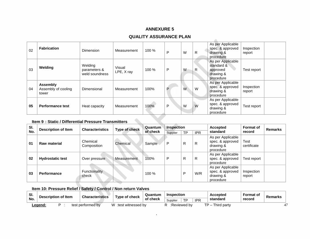
Item 9 : Static / Differential Pressure TransmittersSl.No. Description of Item Characteristics Type of check Quantum
of checkInspection Accepted
standardFormat ofrecord Remarks
Supplier TP IPR
01 Raw material ChemicalComposition Chemical Sample P R R
As per Applicablespec. & approveddrawing &procedure
Testcertificate
02 Hydrostatic test Over pressure Measurement 100% P R RAs per Applicablespec. & approvedprocedure
Test report
03 Performance Functionalitycheck 100 % P W/R
As per Applicablespec. & approveddrawing &procedure
Inspectionreport
Item 10: Pressure Relief / Safety / Control / Non return ValvesSl.No. Description of Item Characteristics Type of check Quantum
of checkInspection Accepted
standardFormat ofrecord Remarks
Supplier TP IPR

ANNEXURE 5QUALITY ASSURANCE PLAN
Legend: P : test performed by W :test witnessed by R :Reviewed by TP – Third party
,
48
01 Raw material ChemicalComposition Chemical Sample P R R
As per Applicablespec. & approveddrawing &procedure
Testcertificate
02 Hydrostatic test Over pressure Measurement 100% P R RAs per Applicablespec. & approvedprocedure
Test report
03 Seat leakage test Seat leakage Measurement 100% P R R
As per Applicablespec. & approveddrawing &procedure
Inspectionreport
04 Performance test Performance Measurement 100% P R R
As per Applicablespec. & approveddrawing &procedure
Inspectionreport
Item 11: Rupture disc
Sl.No. Description of Item Characteristics Type of check Quantum
of checkInspection Accepted
standardFormat ofrecord Remarks
Supplier TP IPR
01 Raw material ChemicalComposition Chemical Sample P R R
As per Applicablespec. & approvedprocedure
Test report
02 Performance test Performance Measurement Sample P W/R R
As per Applicablespec. & approveddrawing &procedure
Inspectionreport
Item 12: Temperature Transmitter / Indicator and level sensor
Sl.No. Description of Item Characteristics Type of check Quantum
of checkInspection Accepted
standardFormat ofrecord
Supplier TP IPR

ANNEXURE 5QUALITY ASSURANCE PLAN
Legend: P : test performed by W :test witnessed by R :Reviewed by TP – Third party
,
49
01 Raw material ChemicalComposition Chemical Sample P R R
As per Applicablespec. & approvedprocedure
Test report
02 Performance Functionalitycheck 100 % P W/R
As per Applicablespec. & approveddrawing &procedure
Inspectionreport
Item 13: Pressure gauge with isolator
Sl.No. Description of Item Characteristics Type of check Quantum
of checkInspection Accepted
standardFormat ofrecord Remarks
Supplier TP IPR
01 Raw material ChemicalComposition Chemical Sample P R R
As per Applicablespec. & approvedprocedure
Test report
02 Performance Functionalitycheck 100 % P W/R
As per Applicablespec. & approveddrawing &procedure
Inspectionreport
Item 14: Controllers
Sl.No. Description of Item Characteristics Type of check Quantum
of checkInspection Accepted
standardFormat ofrecord Remarks
Supplier TP IPR
01 Performance Functionalitycheck 100 % P W/R
As per Applicablespec. & approveddrawing &procedure
Inspectionreport

ANNEXURE 5QUALITY ASSURANCE PLAN
Legend: P : test performed by W :test witnessed by R :Reviewed by TP – Third party
,
50
Item 15: Pressure Regulator
Sl.No. Description of Item Characteristics Type of check Quantum
of checkInspection Accepted
standardFormat ofrecord Remarks
Supplier TP IPR
01 Raw material ChemicalComposition Chemical Sample P R R
As per Applicablespec. & approvedprocedure
Testreport
02 Hydrostatic test Over pressure Measurement 100% P R R
As per Applicablespec. & approveddrawing &procedure
Inspectionreport
03 Performance Functionalitycheck 100 % P W/R
As per Applicablespec. & approveddrawing &procedure
Inspectionreport
Item 16: Pipe and fitting
Sl.No. Description of Item Characteristics Type of check Quantum
of checkInspection Accepted
standardFormat ofrecord
Remarks
Supplier TP IPR
01 Raw material ChemicalComposition Chemical Sample P R R
As per Applicablespec. & approvedprocedure
Testreport
02 Hydrostatic test Over pressure Measurement 100% P R R
As per Applicablespec. & approveddrawing &procedure
Inspectionreport
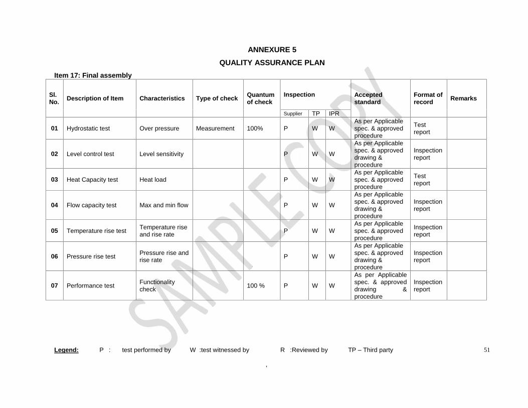
ANNEXURE 5QUALITY ASSURANCE PLAN
Legend: P : test performed by W :test witnessed by R :Reviewed by TP – Third party
,
51
Item 17: Final assembly
Sl.No. Description of Item Characteristics Type of check Quantum
of checkInspection Accepted
standardFormat ofrecord Remarks
Supplier TP IPR
01 Hydrostatic test Over pressure Measurement 100% P W WAs per Applicablespec. & approvedprocedure
Testreport
02 Level control test Level sensitivity P W W
As per Applicablespec. & approveddrawing &procedure
Inspectionreport
03 Heat Capacity test Heat load P W WAs per Applicablespec. & approvedprocedure
Testreport
04 Flow capacity test Max and min flow P W W
As per Applicablespec. & approveddrawing &procedure
Inspectionreport
05 Temperature rise test Temperature riseand rise rate P W W
As per Applicablespec. & approvedprocedure
Inspectionreport
06 Pressure rise test Pressure rise andrise rate P W W
As per Applicablespec. & approveddrawing &procedure
Inspectionreport
07 Performance test Functionalitycheck 100 % P W W
As per Applicablespec. & approveddrawing &procedure
Inspectionreport

52
ABBREVATIONS
HPHT High Pressure High Temperature
WCS Water Circulation System
IPR Institute for Plasma Research
D.M Water De-Mineralized water
DAS Data Acquisition Systems
P & I D Piping & Instrumentation Diagram
T.I Temperature Indicator
T.T Temperature Transmitter
P.I Pressure Indicator
P.T Pressure Transmitter
L.I Level Indicator
L.T Level Transmitters
D.P.T Differential Pressure Transmitter
P.C Pressure Controller
T.C Temperature Controller
F.C Flow Controller
V.F.D Variable Frequency Drive
P.D Pump Positive Displacement Pump
R Reservoir Tank
CT Concrete Tank
P.V Pressure Vessel
B.P Booster Pump
F.M Flow Meter
C.V Control Valve
V Isolation Valve
V.V Vent Valve
D.V Drain Valve
B.P.V By-Pass Valve
N.R.V Non Return Valve
B.V Breather Valve
P.R.V Pressure Relief Valve
S.V Safety Valve
53
R.D Rupture Disc
H.E Heat Exchanger
C Cooler
C.T Cooling Tower
H Heater
SS Stainless Steel
PID Controller Proportional Integral Derivative Controller
ANSI American National Standards Institute
ASME American Society of Mechanical Engineers
TEMA Tubular Exchanger Manufacturers Association
C.A Corrosion Allowance
HL Higher Level
ML Middle Level
LL Lower Level
N2 Nitrogen
LMTD Log. Mean Temperature Difference
CL Tube Layout Constant
CTP Tube Count Calculation Constant
PR Tube pitch ratio
FRP Fiber Reinforced polymer
Fig Figure